EP0194010A2 - Hot air calender roll controller - Google Patents
Hot air calender roll controller Download PDFInfo
- Publication number
- EP0194010A2 EP0194010A2 EP86300465A EP86300465A EP0194010A2 EP 0194010 A2 EP0194010 A2 EP 0194010A2 EP 86300465 A EP86300465 A EP 86300465A EP 86300465 A EP86300465 A EP 86300465A EP 0194010 A2 EP0194010 A2 EP 0194010A2
- Authority
- EP
- European Patent Office
- Prior art keywords
- calender roll
- nozzle
- air
- plenum
- control apparatus
- Prior art date
- Legal status (The legal status is an assumption and is not a legal conclusion. Google has not performed a legal analysis and makes no representation as to the accuracy of the status listed.)
- Granted
Links
Images

Classifications
-
- D—TEXTILES; PAPER
- D21—PAPER-MAKING; PRODUCTION OF CELLULOSE
- D21F—PAPER-MAKING MACHINES; METHODS OF PRODUCING PAPER THEREON
- D21F3/00—Press section of machines for making continuous webs of paper
- D21F3/02—Wet presses
- D21F3/10—Suction rolls, e.g. couch rolls
-
- D—TEXTILES; PAPER
- D21—PAPER-MAKING; PRODUCTION OF CELLULOSE
- D21G—CALENDERS; ACCESSORIES FOR PAPER-MAKING MACHINES
- D21G1/00—Calenders; Smoothing apparatus
- D21G1/02—Rolls; Their bearings
- D21G1/0253—Heating or cooling the rolls; Regulating the temperature
- D21G1/0266—Heating or cooling the rolls; Regulating the temperature using a heat-transfer fluid
- D21G1/0273—Heating or cooling the rolls; Regulating the temperature using a heat-transfer fluid on the exterior surface of the rolls
-
- D—TEXTILES; PAPER
- D21—PAPER-MAKING; PRODUCTION OF CELLULOSE
- D21F—PAPER-MAKING MACHINES; METHODS OF PRODUCING PAPER THEREON
- D21F7/00—Other details of machines for making continuous webs of paper
- D21F7/06—Indicating or regulating the thickness of the layer; Signal devices
Definitions
- the present invention relates to the field of calenders, and more particularly to devices for controlling the diameter of the rolls used in calenders or analagous machines.
- Pressing a material between two calender rolls can change the physical characteristics of the material.
- calendering paper changes its density, thickness and surface features.
- the calendering process is frequently used to manufacture paper and other sheet materials.
- a common problem associated with calendering is the uneven thickness of the calendered material, or "web". Localized variations in the diameter of individual calender rolls creates variations in the spacing or "nip" formed between cooperating rolls. Variations in the nip across the width of a pair of calender rolls produces a web having non-uniform thickness. Therefore, a more uniform thickness can be attained by controlling the local diameter of the rolls.
- the rolls are made of a material that responds to changes in temperature by changing at least one dimension
- Previous devices have used this principle by directing jets of hot or cold air against sections of a rotating calender roll to control its local diameters.
- Nozzles communicating with the interior of each plenum direct these jets of air against the calender roll.
- the nozzles are disposed at intervals corresponding to adjacent sections of the calender roll whose local diameter is to be controlled. Examples of such devices are shown in U.S. Patent No. 2,981,175 to Goyette, U.S. Patent No. 3,177,799 to Justice and U.S. Patent No. 3,770,578 to Spurrell.
- Valves have often been used to control the flow of air through each nozzle. Where separate plenums provide the hot air and cold air, many such devices require two valves and two nozzles to control the diameter of each section of the calender roll. Alternatively, a dual control mechanism may be used to mix the relative volumes of hot and cold air from the two plenums and then release the air through a single nozzle. In either configuration, this redundancy can increase the cost of of these devices.
- valve control mechanisms generally should not exhibit hysteresis effects so that they can obtain repeatable settings regardless of whether the valve is being opened or closed. Furthermore, these control mechanisms usually must be capable of operating at high or low temperatures.
- the rate that air is released through the nozzles is often variable because the air pressure in each plenum depends upon both the number of valves open at one time and the volume of air released through.each nozzle. Thus, the flow of air through the nozzles in these devices can be difficult to control.
- the nip control range is a function of the maximum and minimum temperatures of the air jets.
- the hot air in the plenum is typically heated by waste steam from the facility power plant. Steam supplied by such a power plant usually has a maximum temperature of about 350°F, and inefficiencies in the heat exchange process further limit the maximum temperature of such steam heated air to about 325°F.
- hot air must be continuously supplied to the hot air plenum, even when hot air is not being released through the nozzles. If hot air is not continuously supplied to the hot air plenum, the stagnant air in the plenum may cool to ambient temperature. Then, when a jet of hot air is required to increase the diameter of a section of the calender roll, the cooled stagnant air must first be purged from the plenum. This increases the response time of the device.
- the calender roll control device of the present invention has a number of features which overcome many of the disadvantages of calender roll control devices heretofore known. It can provide a constant flow of air from a single plenum and it can accurately adjust the temperature of a plurality of air jets. Since it requires only one plenum and can operate without flow control mechanisms, the device has a relatively low initial cost. Additionally, it does not require steam heating equipment. Instead, the device heats the air jets only where and when necessary to increase the roll diameter. Furthermore, because it produces hotter air jets than typically provided by steam powered equipment, the device of the present invention can provide more than twice the nip control range on a typical 12" diameter 190°F calender roll.
- the present invention is directed to controllers for controlling local calender roll diameters by directing jets of hot or cold air against selected cylindrical sections of a rotating calender roll.
- the roll is made of a material that responds in at least one dimension to changes in temperature. Thermal expansion or contraction, resulting from localized heating or cooling by the air jets, corrects local nonuniformities in the calender roll diameter.
- the invention comprises a single elongated cold air plenum positioned alongside a calender roll.
- Heating elements such as electrical resistive heaters, are positioned within or adjacent each nozzle. Therefore, when the heating elements are energized, the cold air escaping through the nozzles is heated by contact with the heating elements. It is recognized, however, that other types of heating devices may be used.
- a sensor measures the thickness of the web and power to the heating elements is adjusted to maintain a uniform thickness.
- the volume of air emitted by each nozzle can remain substantially constant. Only the temperature of the air jets need change as the heating elements are energized or de-energized in response to signals from the web thickness sensor.
- the calender roll control apparatus extends alongside a roll 10 of the calendering device.
- the apparatus comprises a cold air plenum 12 and a plurality of nozzles 14 dispersed along the length of the plenum 12 and communicating with its interior.
- a fan 13 pressurizes the plenum 12 with air.
- This pressurized air may be optionally preheated or cooled by any of a variety of well known devices 16 for heating or cooling air.
- the pressurized air in the plenum 12 escapes through the nozzles 14 which direct the air against sections of the calender roll 10 to control its diameter.
- An additional row of nozzles 14 is disposed near the ends of the plenum 12 to compensate for the increased tendency of the calender roll 10 to cool at its ends.
- FIG. 2 is a more detailed cross-sectional view of the device illustrated in FIG. 1.
- At least one electrical heating element 18 is disposed within every nozzle 14 and each nozzle 14, with its internal heating element 18, comprise a unitary heating module 20.
- these modules 20 are detachable from the plenum 12 for convenient repair, inspection or replacement.
- the upper heating module is shown detached from the plenum 12.
- FIG. 3 illustrates a second embodiment of the present invention. It operates in substantially the same manner as the first embodiment. However, in this embodiment, pressurized air from the plenum l12 enters the rear of the heating module 120 and flows directly through the nozzle 114 toward the calender roll 110. Additionally, the nozzles 114 protrude from a concave shroud 132 which acts to constrain the air emitted by the nozzles 114 so that the air remains in contact with the calender roll 110, thus enhancing the efficiency of heat transfer to or from the roll 110. The shroud 132 also prevents cold ambient air from being entrained by the air jets. This would reduce the effective temperature of the jets. Of course, a similar shroud 132 could be used with the embodiment of the invention illustrated in FIG. 1 and FIG. 2.
- the calender roll control device of FIG. 3 is shown supported by an over-center support mechanism 134.
- This mechanism comprises two rigid pivotable arms 136.
- the arms 136 are disposed at either end.of the plenum 112. These arms 136 support the plenum 112 so that the plenum 112 and shroud 132 are pivotable toward or away from the calender roll 110.
- An extendible air cylinder 138 is associated with each pivotable arm l36. Pressurizing the cylinders 138 with air causes them to expand, thus rocking the plenum 112 away from the calender roll 110. In the operating position, however, each air cylinder 138 is pressurized so that the nozzle 114 and shroud 132 are positioned approximately 1/2 inch to approximately 2 inches from the surface of the calender roll 110 depending upon the application and the calender roll control device leans slightly toward the calender roll 110.
- FIG. 4 is a detailed view of a heating module 120 which is usable'with the embodiment of the present invention illustrated in FIG. 3.
- This heating module 120 fits into the heating module socket 142 shown in FIG. 3.
- Two conducting elements 144 extend from the rear of the heating module 120 and plug into an electrical socket 146 positioned within the plenum 112.
- the module 120 may also be easily unpluged for convenient inspection, repair or replacement.
- the module comprises a nozzle 114 which tapers toward the front.
- This nozzle 114 is surrounded by a larger concentric outer tube 148.
- the space between the nozzle 114 and the outer tube 148 is filled with an insulating material 150.
- the heating elements 118 are suspended on a thin mica frame 152 which has a low thermal mass.
- the low thermal mass of the heating elements 118 and mica frame 152 allow the temperature of the air jets to change rapidly in response to signals from the web thickness sensor 154.
- FIG. 5 illustrates a third embodiment of the present invention.
- pressurized air from the plenum 212 enters the rear of the nozzle 214 and flows through the nozzle 214 toward the calender roll 210.
- each nozzle 214 contains internal heating elements 218 which may be used to heat the air as it flows through the nozzle 214.
- the heating elements 218 comprise lengths of resistive wire 256 strung between conductive posts 258 which are disposed at opposite ends of the nozzle 214.
- Each nozzle 214 is 10 inches long, however, the nozzles 214 may be longer or shorter depending upon the desired degree of nip control.
- nozzles 214 have concave ends 260 which conform to the surface of the calender roll 210.
- the concave nozzles 214 in this embodiment serve functions similar to the shroud 132 (see FIG. 3) in the second embodiment of the present invention.
- the concave ends 260 of the nozzle 214 constrain the air emitted from the nozzle orifice 262 so that it remains in contact with the calender roll 210 until the air emerges at the edge of the nozzle 214. Since the hot or cold air emitted from the orifice 262 remains in contact with the calender roll 210 for a longer period of time, more heat is transferred between the roll 210 and the air. Additionally, the concave nozzles 214 prevent cold ambient air from being entrained by the air jets. As previously mentioned, this would reduce the effective temperature of the jets.
- the plenum 212 is pivotally mounted on pivots 264, 266. Pivot 264 is supported by an elongated member 268. When the member 268 retracts in the direction of the arrow 270, the plenum 212, nozzles 214, and heating elements 218 swing away from the calender roll 210. This permits convenient repair, inspection or replacement of the device.
- a sensor 154 measures the thickness of the web 140 and produces a signal corresponding to the measured thickness of each section of web 140. These signals are then fed to a power controlling device 172 which adjusts the power to the heating elements 118 to obtain a web 140 having uniform thickness.
- a power controlling device 172 which adjusts the power to the heating elements 118 to obtain a web 140 having uniform thickness.
- An example of a sensor controlled calender roll control device is shown in U.S. Patent No. 4,114,528 to Walker.
- more or less power is applied to the heating elements 118 in the nozzles 114 adjacent those sections of the calender roll 110 whose diameters are to be adjusted.
- the sections of the calender roll 110 producing too thick a web 140 are heated by energizing the heating elements 118 in an adjacent nozzle 114.
- the greater the amount of power applied to the heating elements 118 the more hot air impinges against the calender roll 110 and the more thermal expansion occurs. For example, with 1 psig plenum pressure and a 0.625 inch nozzle diameter, a 5.5 Kw heating element 118 will heat 65°F air to 600°F in about six seconds.
- the power controlling device 172 directs less power to the adjacent heating elements 118 or it turns these heating elements 118 completely off. As the power to the heating elements is decreased, the adjacent sections of calender roll 110 are subjected to a flow of colder air. The colder air causes the adjacent sections of the calender roll 110 to contract, thereby increasing the local nip spacing and producing a thicker section of web.
Abstract
Description
- The present invention relates to the field of calenders, and more particularly to devices for controlling the diameter of the rolls used in calenders or analagous machines.
- Pressing a material between two calender rolls can change the physical characteristics of the material. For example, calendering paper changes its density, thickness and surface features. Thus, the calendering process is frequently used to manufacture paper and other sheet materials.
- A common problem associated with calendering is the uneven thickness of the calendered material, or "web". Localized variations in the diameter of individual calender rolls creates variations in the spacing or "nip" formed between cooperating rolls. Variations in the nip across the width of a pair of calender rolls produces a web having non-uniform thickness. Therefore, a more uniform thickness can be attained by controlling the local diameter of the rolls.
- If the rolls are made of a material that responds to changes in temperature by changing at least one dimension, one may control local roll diameters by varying the temperature of selected cylindrical sections of the calender roll. Previous devices have used this principle by directing jets of hot or cold air against sections of a rotating calender roll to control its local diameters.
- Many of these devices blow jets of hot air from a supply plenum against selected sections of the calender roll to increase its local diameter and thus decrease the local thickness of the web. Alternatively, when these devices blow jets cold air from a separate supply plenum against selected cylindrical sections of the calender roll, the adjacent sections contract. This decreases the local roll diameter and increases the local thickness of the web.
- Nozzles communicating with the interior of each plenum direct these jets of air against the calender roll. The nozzles are disposed at intervals corresponding to adjacent sections of the calender roll whose local diameter is to be controlled. Examples of such devices are shown in U.S. Patent No. 2,981,175 to Goyette, U.S. Patent No. 3,177,799 to Justice and U.S. Patent No. 3,770,578 to Spurrell.
- Valves have often been used to control the flow of air through each nozzle. Where separate plenums provide the hot air and cold air, many such devices require two valves and two nozzles to control the diameter of each section of the calender roll. Alternatively, a dual control mechanism may be used to mix the relative volumes of hot and cold air from the two plenums and then release the air through a single nozzle. In either configuration, this redundancy can increase the cost of of these devices.
- Another problem experienced with controllers of this type is that accurate control of the roll diameter can require precise metering of the air jets. Therefore, the valve control mechanisms generally should not exhibit hysteresis effects so that they can obtain repeatable settings regardless of whether the valve is being opened or closed. Furthermore, these control mechanisms usually must be capable of operating at high or low temperatures. However, even when the valves work properly and the control mechanisms accurately control the size of the valve orifices, the rate that air is released through the nozzles is often variable because the air pressure in each plenum depends upon both the number of valves open at one time and the volume of air released through.each nozzle. Thus, the flow of air through the nozzles in these devices can be difficult to control.
- These devices are also subject to other limitations and inefficiencies. For example, the nip control range is a function of the maximum and minimum temperatures of the air jets. However, the hot air in the plenum is typically heated by waste steam from the facility power plant. Steam supplied by such a power plant usually has a maximum temperature of about 350°F, and inefficiencies in the heat exchange process further limit the maximum temperature of such steam heated air to about 325°F.
- Furthermore, to maintain the air temperature at 325°F, hot air must be continuously supplied to the hot air plenum, even when hot air is not being released through the nozzles. If hot air is not continuously supplied to the hot air plenum, the stagnant air in the plenum may cool to ambient temperature. Then, when a jet of hot air is required to increase the diameter of a section of the calender roll, the cooled stagnant air must first be purged from the plenum. This increases the response time of the device.
- The calender roll control device of the present invention has a number of features which overcome many of the disadvantages of calender roll control devices heretofore known. It can provide a constant flow of air from a single plenum and it can accurately adjust the temperature of a plurality of air jets. Since it requires only one plenum and can operate without flow control mechanisms, the device has a relatively low initial cost. Additionally, it does not require steam heating equipment. Instead, the device heats the air jets only where and when necessary to increase the roll diameter. Furthermore, because it produces hotter air jets than typically provided by steam powered equipment, the device of the present invention can provide more than twice the nip control range on a typical 12" diameter 190°F calender roll. These and other advantages will become apparent in the description which follows.
- The present invention is directed to controllers for controlling local calender roll diameters by directing jets of hot or cold air against selected cylindrical sections of a rotating calender roll. The roll is made of a material that responds in at least one dimension to changes in temperature. Thermal expansion or contraction, resulting from localized heating or cooling by the air jets, corrects local nonuniformities in the calender roll diameter.
- In the illustrated embodiments, the invention comprises a single elongated cold air plenum positioned alongside a calender roll. A plurality of nozzles, disposed along the length of the plenum, direct jets of air at cylindrical sections of the roll. Heating elements, such as electrical resistive heaters, are positioned within or adjacent each nozzle. Therefore, when the heating elements are energized, the cold air escaping through the nozzles is heated by contact with the heating elements. It is recognized, however, that other types of heating devices may be used.
- A sensor measures the thickness of the web and power to the heating elements is adjusted to maintain a uniform thickness. The volume of air emitted by each nozzle can remain substantially constant. Only the temperature of the air jets need change as the heating elements are energized or de-energized in response to signals from the web thickness sensor.
- There now follows a description of several examples of apparatus according to the invention. It will be understood that the description, which is to be read with reference to the drawings, is given by way of example only and not by way of limitation.
- In the drawings:-
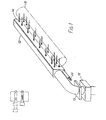
- FIG. 1 is a perspective view of one embodiment of the present invention showing a plurality of nozzles disposed along the length of the plenum and directing air against a calender roll.
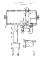
- FIG. 2 is a cross-sectional view of the embodiment illustrated in Fig. 1 showing removable heating modules.
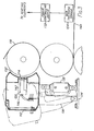
- FIG. 3 illustrates another embodiment of the present invention having a single row of nozzles directed against a calender roll and a shroud for preventing cold air entrainment. This embodiment is supported by an over-center support mechanism.
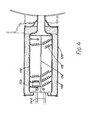
- FIG. 4 is a detailed illustration of a heating module usable with the embodiment of FIG. 3.
- FIG. 5 is a cross-sectional plan view of another preferred embodiment of the present invention having a concave nozzle to prevent cold air entrainment.
- Like reference numbers in the various figures refer to like elements.
- In one embodiment of the present invention, illustrated in FIG. 1, the calender roll control apparatus extends alongside a
roll 10 of the calendering device. The apparatus comprises acold air plenum 12 and a plurality ofnozzles 14 dispersed along the length of theplenum 12 and communicating with its interior. A fan 13 pressurizes theplenum 12 with air. This pressurized air may be optionally preheated or cooled by any of a variety of well knowndevices 16 for heating or cooling air. The pressurized air in theplenum 12 escapes through thenozzles 14 which direct the air against sections of thecalender roll 10 to control its diameter. An additional row ofnozzles 14 is disposed near the ends of theplenum 12 to compensate for the increased tendency of thecalender roll 10 to cool at its ends. - FIG. 2 is a more detailed cross-sectional view of the device illustrated in FIG. 1. At least one
electrical heating element 18 is disposed within everynozzle 14 and eachnozzle 14, with itsinternal heating element 18, comprise aunitary heating module 20. As shown in FIG. 2, thesemodules 20 are detachable from theplenum 12 for convenient repair, inspection or replacement. In FIG. 2, the upper heating module is shown detached from theplenum 12. - Air from the
plenum 12 enters theheating module 20 throughholes 22 in themodule casing 24 provided for this purpose. The air then flows through achannel 26 toward the rear of theheating module 20 where it enters the interior of thenozzle 14.Arrows nozzle 14 contacts the heating elements 18: Therefore, although cold air in theplenum 12 escapes at a constant rate through each nozzle.14, the temperature of the escaping air can be elevated by energizing theheating elements 18. - FIG. 3 illustrates a second embodiment of the present invention. It operates in substantially the same manner as the first embodiment. However, in this embodiment, pressurized air from the plenum l12 enters the rear of the
heating module 120 and flows directly through thenozzle 114 toward thecalender roll 110. Additionally, thenozzles 114 protrude from aconcave shroud 132 which acts to constrain the air emitted by thenozzles 114 so that the air remains in contact with thecalender roll 110, thus enhancing the efficiency of heat transfer to or from theroll 110. Theshroud 132 also prevents cold ambient air from being entrained by the air jets. This would reduce the effective temperature of the jets. Of course, asimilar shroud 132 could be used with the embodiment of the invention illustrated in FIG. 1 and FIG. 2. - The calender roll control device of FIG. 3, is shown supported by an
over-center support mechanism 134. This mechanism comprises two rigidpivotable arms 136. Thearms 136 are disposed at either end.of theplenum 112. Thesearms 136 support theplenum 112 so that theplenum 112 andshroud 132 are pivotable toward or away from thecalender roll 110. - An
extendible air cylinder 138 is associated with each pivotable arm l36. Pressurizing thecylinders 138 with air causes them to expand, thus rocking theplenum 112 away from thecalender roll 110. In the operating position, however, eachair cylinder 138 is pressurized so that thenozzle 114 andshroud 132 are positioned approximately 1/2 inch to approximately 2 inches from the surface of thecalender roll 110 depending upon the application and the calender roll control device leans slightly toward thecalender roll 110. In this metastable position, if theweb 140 breaks and wraps around theroll 110, a slight forceful contact between theweb 140 and thenozzles 114 orshroud 132 will be sufficient to rock the device back away from thecalender roll 110 and thus avoid damage to the device. - FIG. 4 is a detailed view of a
heating module 120 which is usable'with the embodiment of the present invention illustrated in FIG. 3. Thisheating module 120 fits into theheating module socket 142 shown in FIG. 3. Two conductingelements 144 extend from the rear of theheating module 120 and plug into anelectrical socket 146 positioned within theplenum 112. Themodule 120 may also be easily unpluged for convenient inspection, repair or replacement. - The module comprises a
nozzle 114 which tapers toward the front. Thisnozzle 114 is surrounded by a larger concentricouter tube 148. The space between thenozzle 114 and theouter tube 148 is filled with an insulatingmaterial 150. - The
heating elements 118 are suspended on athin mica frame 152 which has a low thermal mass. The low thermal mass of theheating elements 118 andmica frame 152 allow the temperature of the air jets to change rapidly in response to signals from theweb thickness sensor 154. - FIG. 5 illustrates a third embodiment of the present invention. In this embodiment, pressurized air from the
plenum 212 enters the rear of thenozzle 214 and flows through thenozzle 214 toward thecalender roll 210. As in the first and second embodiments, eachnozzle 214 containsinternal heating elements 218 which may be used to heat the air as it flows through thenozzle 214. Theheating elements 218 comprise lengths ofresistive wire 256 strung betweenconductive posts 258 which are disposed at opposite ends of thenozzle 214. Eachnozzle 214 is 10 inches long, however, thenozzles 214 may be longer or shorter depending upon the desired degree of nip control. - These
nozzles 214 have concave ends 260 which conform to the surface of thecalender roll 210. Theconcave nozzles 214 in this embodiment serve functions similar to the shroud 132 (see FIG. 3) in the second embodiment of the present invention. The concave ends 260 of thenozzle 214 constrain the air emitted from thenozzle orifice 262 so that it remains in contact with thecalender roll 210 until the air emerges at the edge of thenozzle 214. Since the hot or cold air emitted from theorifice 262 remains in contact with thecalender roll 210 for a longer period of time, more heat is transferred between theroll 210 and the air. Additionally, theconcave nozzles 214 prevent cold ambient air from being entrained by the air jets. As previously mentioned, this would reduce the effective temperature of the jets. - The
plenum 212 is pivotally mounted onpivots Pivot 264 is supported by anelongated member 268. When themember 268 retracts in the direction of thearrow 270, theplenum 212,nozzles 214, andheating elements 218 swing away from thecalender roll 210. This permits convenient repair, inspection or replacement of the device. - Each embodiment of the present invention operates in substantially the same manner. Therefore, the operation of the device of the present invention will be described with reference to only the second embodiment illustrated in FIG. 3 and FIG. 4. However, the description which follows is also applicable to the other embodiments.
- During operation of the invention, a
sensor 154 measures the thickness of theweb 140 and produces a signal corresponding to the measured thickness of each section ofweb 140. These signals are then fed to apower controlling device 172 which adjusts the power to theheating elements 118 to obtain aweb 140 having uniform thickness. An example of a sensor controlled calender roll control device is shown in U.S. Patent No. 4,114,528 to Walker. - Depending upon the degree of deviation of the
web 140 from the desired thickness, more or less power is applied to theheating elements 118 in thenozzles 114 adjacent those sections of thecalender roll 110 whose diameters are to be adjusted. The sections of thecalender roll 110 producing too thick aweb 140 are heated by energizing theheating elements 118 in anadjacent nozzle 114. The greater the amount of power applied to theheating elements 118, the more hot air impinges against thecalender roll 110 and the more thermal expansion occurs. For example, with 1 psig plenum pressure and a 0.625 inch nozzle diameter, a 5.5Kw heating element 118 will heat 65°F air to 600°F in about six seconds. - Alternatively, when the
sensing device 154 detects athin web section 140 thepower controlling device 172 directs less power to theadjacent heating elements 118 or it turns theseheating elements 118 completely off. As the power to the heating elements is decreased, the adjacent sections ofcalender roll 110 are subjected to a flow of colder air. The colder air causes the adjacent sections of thecalender roll 110 to contract, thereby increasing the local nip spacing and producing a thicker section of web. - Many steam heated apparatuses for controlling the thickness of the
calendered web 140 are limited to heating air to a maximum temperature of about 325°F. In contrast, the present invention can achieve air temperatures of 600°F. This higher temperature provides more than twice the control range on a typical 190°F, 12-inch roll 110. Additionally, since the air flow through everynozzle 114 remains constant, more accurate control is possible. The temperature of the air emerging from eachnozzle 114 is independent of the temperature of the air emerging from the other nozzles - 114. - Two preferred embodiments of the present invention have been described. Nevertheless, it is understood that one may make various modifications without departing from the scope of the invention. For example, instead of continuously varying the level of power to the heating elements, the power may be switched on and off for varying percentages of a duty cycle. Furthermore, nozzles of different shapes and sizes are not beyond the scope of the present invention. Thus, the invention is not limited to the preferred embodiments described herein.
Claims (10)
wherein each nozzle (14) and the heating element (18) disposed within the nozzle form a unitary module which is separately detachable from the plenum.
wherein the end of the nozzle (14) is concave, having approximately the same curvature as the surface of the calender roll and wherein the nozzle is disposed so that the curvature of the nozzle is aligned with the curvature of the calender roll.
Applications Claiming Priority (2)
| Application Number | Priority Date | Filing Date | Title |
|---|---|---|---|
| US06/694,855 US4768433A (en) | 1985-01-25 | 1985-01-25 | Hot air calender roll controller |
| US694855 | 1996-08-08 |
Publications (3)
| Publication Number | Publication Date |
|---|---|
| EP0194010A2 true EP0194010A2 (en) | 1986-09-10 |
| EP0194010A3 EP0194010A3 (en) | 1987-01-21 |
| EP0194010B1 EP0194010B1 (en) | 1990-08-29 |
Family
ID=24790531
Family Applications (1)
| Application Number | Title | Priority Date | Filing Date |
|---|---|---|---|
| EP86300465A Expired - Lifetime EP0194010B1 (en) | 1985-01-25 | 1986-01-23 | Hot air calender roll controller |
Country Status (8)
| Country | Link |
|---|---|
| US (1) | US4768433A (en) |
| EP (1) | EP0194010B1 (en) |
| JP (1) | JPH0784718B2 (en) |
| KR (1) | KR930002073B1 (en) |
| CA (1) | CA1242099A (en) |
| DE (1) | DE3673667D1 (en) |
| FI (1) | FI86094C (en) |
| IE (1) | IE57210B1 (en) |
Cited By (2)
| Publication number | Priority date | Publication date | Assignee | Title |
|---|---|---|---|---|
| DE19826063B4 (en) * | 1998-06-12 | 2004-03-11 | Voith Paper Patent Gmbh | Cooling device for a material web |
| DE102013006263A1 (en) * | 2013-04-11 | 2014-10-16 | Ima Klessmann Gmbh Holzbearbeitungssysteme | Device for processing plate-shaped workpieces |
Families Citing this family (41)
| Publication number | Priority date | Publication date | Assignee | Title |
|---|---|---|---|---|
| US4738196A (en) * | 1985-01-28 | 1988-04-19 | Measurex Corporation | Air heater for a calender roll diameter controller |
| US4823688A (en) * | 1987-08-10 | 1989-04-25 | Beloit Corporation | Calendering apparatus using inductive heating for hot-calendering a paper web |
| DE3730392A1 (en) * | 1987-09-10 | 1989-03-30 | Winkler Duennebier Kg Masch | METHOD AND DEVICE FOR KEEPING THE CUTTING CONDITIONS CONSTANT ON A ROTARY PUNCH |
| US4867054A (en) * | 1988-01-26 | 1989-09-19 | Thermo Electron Web Systems, Inc. | Caliper control system |
| DE3802345C1 (en) * | 1988-01-27 | 1989-02-02 | Patzner Gmbh + Co, 6990 Bad Mergentheim, De | |
| US4984622A (en) * | 1989-10-02 | 1991-01-15 | Process Automation Business, Inc. | Apparatus for supplying temperature regulated air to a calender roll |
| US5728309A (en) | 1991-04-05 | 1998-03-17 | The Boeing Company | Method for achieving thermal uniformity in induction processing of organic matrix composites or metals |
| US5641422A (en) * | 1991-04-05 | 1997-06-24 | The Boeing Company | Thermoplastic welding of organic resin composites using a fixed coil induction heater |
| US5410132A (en) * | 1991-10-15 | 1995-04-25 | The Boeing Company | Superplastic forming using induction heating |
| US5808281A (en) | 1991-04-05 | 1998-09-15 | The Boeing Company | Multilayer susceptors for achieving thermal uniformity in induction processing of organic matrix composites or metals |
| US5723849A (en) | 1991-04-05 | 1998-03-03 | The Boeing Company | Reinforced susceptor for induction or resistance welding of thermoplastic composites |
| US7126096B1 (en) | 1991-04-05 | 2006-10-24 | Th Boeing Company | Resistance welding of thermoplastics in aerospace structure |
| US5793024A (en) | 1991-04-05 | 1998-08-11 | The Boeing Company | Bonding using induction heating |
| US5624594A (en) | 1991-04-05 | 1997-04-29 | The Boeing Company | Fixed coil induction heater for thermoplastic welding |
| US5645744A (en) | 1991-04-05 | 1997-07-08 | The Boeing Company | Retort for achieving thermal uniformity in induction processing of organic matrix composites or metals |
| US5444220A (en) * | 1991-10-18 | 1995-08-22 | The Boeing Company | Asymmetric induction work coil for thermoplastic welding |
| US5508496A (en) * | 1991-10-18 | 1996-04-16 | The Boeing Company | Selvaged susceptor for thermoplastic welding by induction heating |
| US5500511A (en) * | 1991-10-18 | 1996-03-19 | The Boeing Company | Tailored susceptors for induction welding of thermoplastic |
| US5611396A (en) * | 1994-08-19 | 1997-03-18 | Abb Industrial Systems, Inc. | Method and apparatus for throttle valve control of a calender roll actuator |
| US5710412A (en) * | 1994-09-28 | 1998-01-20 | The Boeing Company | Fluid tooling for thermoplastic welding |
| US5660669A (en) * | 1994-12-09 | 1997-08-26 | The Boeing Company | Thermoplastic welding |
| US5573613A (en) * | 1995-01-03 | 1996-11-12 | Lunden; C. David | Induction thermometry |
| US5486684A (en) * | 1995-01-03 | 1996-01-23 | The Boeing Company | Multipass induction heating for thermoplastic welding |
| DE19520442C2 (en) * | 1995-06-03 | 2000-05-31 | Voith Sulzer Papiermasch Gmbh | Roller press |
| US5717191A (en) * | 1995-06-06 | 1998-02-10 | The Boeing Company | Structural susceptor for thermoplastic welding |
| US6602810B1 (en) | 1995-06-06 | 2003-08-05 | The Boeing Company | Method for alleviating residual tensile strain in thermoplastic welds |
| US5705795A (en) * | 1995-06-06 | 1998-01-06 | The Boeing Company | Gap filling for thermoplastic welds |
| US5756973A (en) * | 1995-06-07 | 1998-05-26 | The Boeing Company | Barbed susceptor for improviing pulloff strength in welded thermoplastic composite structures |
| US5829716A (en) * | 1995-06-07 | 1998-11-03 | The Boeing Company | Welded aerospace structure using a hybrid metal webbed composite beam |
| US5556565A (en) * | 1995-06-07 | 1996-09-17 | The Boeing Company | Method for composite welding using a hybrid metal webbed composite beam |
| US5760379A (en) * | 1995-10-26 | 1998-06-02 | The Boeing Company | Monitoring the bond line temperature in thermoplastic welds |
| US5916469A (en) * | 1996-06-06 | 1999-06-29 | The Boeing Company | Susceptor integration into reinforced thermoplastic composites |
| US5869814A (en) * | 1996-07-29 | 1999-02-09 | The Boeing Company | Post-weld annealing of thermoplastic welds |
| US5902935A (en) * | 1996-09-03 | 1999-05-11 | Georgeson; Gary E. | Nondestructive evaluation of composite bonds, especially thermoplastic induction welds |
| JP2999425B2 (en) * | 1996-11-06 | 2000-01-17 | 明産株式会社 | Contact pressure control device for rotary cutter |
| US6284089B1 (en) | 1997-12-23 | 2001-09-04 | The Boeing Company | Thermoplastic seam welds |
| US6000328A (en) * | 1998-03-05 | 1999-12-14 | Impact Systems, Inc. | Gloss control system using air jets |
| ITMI20011660A1 (en) * | 2001-07-31 | 2003-01-31 | Electronic Systems Spa | DEVICE AND PROCEDURE FOR ADJUSTING THE DIAMETER PROFILE OF A CALENDER ROLL |
| JP5677865B2 (en) * | 2011-01-20 | 2015-02-25 | ユニ・チャーム株式会社 | Apparatus and method for reducing absorber thickness |
| JP6707842B2 (en) | 2015-01-13 | 2020-06-10 | セイコーエプソン株式会社 | Sheet manufacturing apparatus and sheet manufacturing method |
| WO2016113803A1 (en) * | 2015-01-13 | 2016-07-21 | セイコーエプソン株式会社 | Sheet manufacturing device and sheet manufacturing method |
Citations (3)
| Publication number | Priority date | Publication date | Assignee | Title |
|---|---|---|---|---|
| US2981175A (en) * | 1957-11-06 | 1961-04-25 | Lodding Engineering Corp | Sheet caliper control device for paper making |
| US3770578A (en) * | 1971-05-12 | 1973-11-06 | Midland Ross Corp | Method for controlling caliper |
| DE2708390A1 (en) * | 1976-03-02 | 1977-09-08 | Midland Ross Corp | METHOD AND DEVICE FOR CONTROLLING THE THICKNESS OF RAIL MATERIAL |
Family Cites Families (8)
| Publication number | Priority date | Publication date | Assignee | Title |
|---|---|---|---|---|
| US3177799A (en) * | 1963-01-10 | 1965-04-13 | Beloit Corp | Apparatus for selectively temperature conditioning calenders |
| US3203678A (en) * | 1963-05-01 | 1965-08-31 | Warren S D Co | Temperature control system for rolls |
| US3266561A (en) * | 1963-12-23 | 1966-08-16 | Beloit Iron Works | Method and means for correcting the crown of a roll |
| US3702912A (en) * | 1971-02-04 | 1972-11-14 | Wean United Inc | Method of and apparatus for calendering strip-like material |
| DE3033482C2 (en) * | 1980-09-05 | 1983-06-23 | Kleinewefers Gmbh, 4150 Krefeld | Electromagnetic heating roller |
| US4384514A (en) * | 1981-03-03 | 1983-05-24 | Consolidated-Bathurst Inc. | Nip control method and apparatus |
| CH662837A5 (en) * | 1983-02-10 | 1987-10-30 | Escher Wyss Ag | CALENDAR FOR PRESSURE AND HEAT TREATMENT OF PRODUCTS. |
| US4545857A (en) * | 1984-01-16 | 1985-10-08 | Weyerhaeuser Company | Louvered steam box for controlling moisture profile of a fibrous web |
-
1985
- 1985-01-25 US US06/694,855 patent/US4768433A/en not_active Expired - Lifetime
-
1986
- 1986-01-23 DE DE8686300465T patent/DE3673667D1/en not_active Expired - Lifetime
- 1986-01-23 EP EP86300465A patent/EP0194010B1/en not_active Expired - Lifetime
- 1986-01-24 KR KR1019860000460A patent/KR930002073B1/en not_active IP Right Cessation
- 1986-01-24 JP JP61013609A patent/JPH0784718B2/en not_active Expired - Lifetime
- 1986-01-24 CA CA000500308A patent/CA1242099A/en not_active Expired
- 1986-01-24 FI FI860353A patent/FI86094C/en not_active IP Right Cessation
- 1986-01-24 IE IE216/86A patent/IE57210B1/en not_active IP Right Cessation
Patent Citations (3)
| Publication number | Priority date | Publication date | Assignee | Title |
|---|---|---|---|---|
| US2981175A (en) * | 1957-11-06 | 1961-04-25 | Lodding Engineering Corp | Sheet caliper control device for paper making |
| US3770578A (en) * | 1971-05-12 | 1973-11-06 | Midland Ross Corp | Method for controlling caliper |
| DE2708390A1 (en) * | 1976-03-02 | 1977-09-08 | Midland Ross Corp | METHOD AND DEVICE FOR CONTROLLING THE THICKNESS OF RAIL MATERIAL |
Cited By (2)
| Publication number | Priority date | Publication date | Assignee | Title |
|---|---|---|---|---|
| DE19826063B4 (en) * | 1998-06-12 | 2004-03-11 | Voith Paper Patent Gmbh | Cooling device for a material web |
| DE102013006263A1 (en) * | 2013-04-11 | 2014-10-16 | Ima Klessmann Gmbh Holzbearbeitungssysteme | Device for processing plate-shaped workpieces |
Also Published As
| Publication number | Publication date |
|---|---|
| CA1242099A (en) | 1988-09-20 |
| IE57210B1 (en) | 1992-06-03 |
| FI860353A0 (en) | 1986-01-24 |
| FI860353A (en) | 1986-07-26 |
| JPH0784718B2 (en) | 1995-09-13 |
| US4768433A (en) | 1988-09-06 |
| KR930002073B1 (en) | 1993-03-26 |
| EP0194010A3 (en) | 1987-01-21 |
| DE3673667D1 (en) | 1990-10-04 |
| EP0194010B1 (en) | 1990-08-29 |
| IE860216L (en) | 1986-07-25 |
| JPS61231296A (en) | 1986-10-15 |
| FI86094C (en) | 1992-07-10 |
| FI86094B (en) | 1992-03-31 |
| KR860005936A (en) | 1986-08-16 |
Similar Documents
| Publication | Publication Date | Title |
|---|---|---|
| US4768433A (en) | Hot air calender roll controller | |
| EP0253547B1 (en) | Air heater for a calender roll diameter controller | |
| US4685389A (en) | Hot air calender roll controller | |
| US4573402A (en) | Caliper control system and method | |
| US4364156A (en) | Apparatus for heated pressurized fluid stream treatment of substrate material | |
| CN101775481B (en) | Strip material treatment apparatus | |
| JP4253509B2 (en) | Process for controlling web temperature and apparatus used for temperature control | |
| US5416979A (en) | Paper web dryer and paper moisture profiling system | |
| US4658716A (en) | Infrared heating calender roll controller | |
| US4323760A (en) | Method and apparatus for temperature control of heated fluid in a fluid handling system | |
| US5045342A (en) | Independent heat moisture control system for gloss optimization | |
| US4671173A (en) | Steam jet calender controller with condensate suction | |
| CA1286901C (en) | Air shower apparatus and method | |
| WO1990014216A1 (en) | Calendering control system | |
| CA2151772C (en) | Method and apparatus for throttle valve control of a calender roll actuator | |
| EP1281810B1 (en) | Device and procedure for adjusting the diameter profile of a calender roller | |
| JPH0724991A (en) | Double-side rotary printing method and press | |
| JPH0375676B2 (en) | ||
| JPH10251989A (en) | Slice regulator for headbox of paper machine | |
| JPH11286888A (en) | Gloss regulator using air jet | |
| GB2284278A (en) | Temperature control in photographic materials |
Legal Events
| Date | Code | Title | Description |
|---|---|---|---|
| PUAI | Public reference made under article 153(3) epc to a published international application that has entered the european phase |
Free format text: ORIGINAL CODE: 0009012 |
|
| AK | Designated contracting states |
Kind code of ref document: A2 Designated state(s): DE FR GB IT SE |
|
| PUAL | Search report despatched |
Free format text: ORIGINAL CODE: 0009013 |
|
| AK | Designated contracting states |
Kind code of ref document: A3 Designated state(s): DE FR GB IT SE |
|
| 17P | Request for examination filed |
Effective date: 19870716 |
|
| 17Q | First examination report despatched |
Effective date: 19880915 |
|
| GRAA | (expected) grant |
Free format text: ORIGINAL CODE: 0009210 |
|
| AK | Designated contracting states |
Kind code of ref document: B1 Designated state(s): DE FR GB IT SE |
|
| ITF | It: translation for a ep patent filed |
Owner name: DOTT. FRANCO CICOGNA |
|
| REF | Corresponds to: |
Ref document number: 3673667 Country of ref document: DE Date of ref document: 19901004 |
|
| ET | Fr: translation filed | ||
| PLBE | No opposition filed within time limit |
Free format text: ORIGINAL CODE: 0009261 |
|
| STAA | Information on the status of an ep patent application or granted ep patent |
Free format text: STATUS: NO OPPOSITION FILED WITHIN TIME LIMIT |
|
| 26N | No opposition filed | ||
| ITTA | It: last paid annual fee | ||
| EAL | Se: european patent in force in sweden |
Ref document number: 86300465.1 |
|
| REG | Reference to a national code |
Ref country code: GB Ref legal event code: IF02 |
|
| PGFP | Annual fee paid to national office [announced via postgrant information from national office to epo] |
Ref country code: GB Payment date: 20041210 Year of fee payment: 20 |
|
| PGFP | Annual fee paid to national office [announced via postgrant information from national office to epo] |
Ref country code: FR Payment date: 20050105 Year of fee payment: 20 |
|
| PGFP | Annual fee paid to national office [announced via postgrant information from national office to epo] |
Ref country code: SE Payment date: 20050107 Year of fee payment: 20 |
|
| PGFP | Annual fee paid to national office [announced via postgrant information from national office to epo] |
Ref country code: IT Payment date: 20050119 Year of fee payment: 20 |
|
| PGFP | Annual fee paid to national office [announced via postgrant information from national office to epo] |
Ref country code: DE Payment date: 20050131 Year of fee payment: 20 |
|
| PG25 | Lapsed in a contracting state [announced via postgrant information from national office to epo] |
Ref country code: GB Free format text: LAPSE BECAUSE OF EXPIRATION OF PROTECTION Effective date: 20060122 |
|
| REG | Reference to a national code |
Ref country code: GB Ref legal event code: PE20 |
|
| EUG | Se: european patent has lapsed |