EP0189918B1 - Heat-fusion pipe fitting system - Google Patents
Heat-fusion pipe fitting system Download PDFInfo
- Publication number
- EP0189918B1 EP0189918B1 EP19860101174 EP86101174A EP0189918B1 EP 0189918 B1 EP0189918 B1 EP 0189918B1 EP 19860101174 EP19860101174 EP 19860101174 EP 86101174 A EP86101174 A EP 86101174A EP 0189918 B1 EP0189918 B1 EP 0189918B1
- Authority
- EP
- European Patent Office
- Prior art keywords
- fitting
- code
- heating
- fusion
- heat
- Prior art date
- Legal status (The legal status is an assumption and is not a legal conclusion. Google has not performed a legal analysis and makes no representation as to the accuracy of the status listed.)
- Expired - Lifetime
Links
Images


Classifications
-
- B—PERFORMING OPERATIONS; TRANSPORTING
- B29—WORKING OF PLASTICS; WORKING OF SUBSTANCES IN A PLASTIC STATE IN GENERAL
- B29C—SHAPING OR JOINING OF PLASTICS; SHAPING OF MATERIAL IN A PLASTIC STATE, NOT OTHERWISE PROVIDED FOR; AFTER-TREATMENT OF THE SHAPED PRODUCTS, e.g. REPAIRING
- B29C65/00—Joining or sealing of preformed parts, e.g. welding of plastics materials; Apparatus therefor
- B29C65/02—Joining or sealing of preformed parts, e.g. welding of plastics materials; Apparatus therefor by heating, with or without pressure
- B29C65/34—Joining or sealing of preformed parts, e.g. welding of plastics materials; Apparatus therefor by heating, with or without pressure using heated elements which remain in the joint, e.g. "verlorenes Schweisselement"
- B29C65/3404—Joining or sealing of preformed parts, e.g. welding of plastics materials; Apparatus therefor by heating, with or without pressure using heated elements which remain in the joint, e.g. "verlorenes Schweisselement" characterised by the type of heated elements which remain in the joint
- B29C65/342—Joining or sealing of preformed parts, e.g. welding of plastics materials; Apparatus therefor by heating, with or without pressure using heated elements which remain in the joint, e.g. "verlorenes Schweisselement" characterised by the type of heated elements which remain in the joint comprising at least a single wire, e.g. in the form of a winding
-
- B—PERFORMING OPERATIONS; TRANSPORTING
- B29—WORKING OF PLASTICS; WORKING OF SUBSTANCES IN A PLASTIC STATE IN GENERAL
- B29C—SHAPING OR JOINING OF PLASTICS; SHAPING OF MATERIAL IN A PLASTIC STATE, NOT OTHERWISE PROVIDED FOR; AFTER-TREATMENT OF THE SHAPED PRODUCTS, e.g. REPAIRING
- B29C65/00—Joining or sealing of preformed parts, e.g. welding of plastics materials; Apparatus therefor
- B29C65/02—Joining or sealing of preformed parts, e.g. welding of plastics materials; Apparatus therefor by heating, with or without pressure
- B29C65/34—Joining or sealing of preformed parts, e.g. welding of plastics materials; Apparatus therefor by heating, with or without pressure using heated elements which remain in the joint, e.g. "verlorenes Schweisselement"
- B29C65/36—Joining or sealing of preformed parts, e.g. welding of plastics materials; Apparatus therefor by heating, with or without pressure using heated elements which remain in the joint, e.g. "verlorenes Schweisselement" heated by induction
- B29C65/3604—Joining or sealing of preformed parts, e.g. welding of plastics materials; Apparatus therefor by heating, with or without pressure using heated elements which remain in the joint, e.g. "verlorenes Schweisselement" heated by induction characterised by the type of elements heated by induction which remain in the joint
- B29C65/362—Joining or sealing of preformed parts, e.g. welding of plastics materials; Apparatus therefor by heating, with or without pressure using heated elements which remain in the joint, e.g. "verlorenes Schweisselement" heated by induction characterised by the type of elements heated by induction which remain in the joint comprising at least a single wire, e.g. in the form of a winding
-
- B—PERFORMING OPERATIONS; TRANSPORTING
- B29—WORKING OF PLASTICS; WORKING OF SUBSTANCES IN A PLASTIC STATE IN GENERAL
- B29C—SHAPING OR JOINING OF PLASTICS; SHAPING OF MATERIAL IN A PLASTIC STATE, NOT OTHERWISE PROVIDED FOR; AFTER-TREATMENT OF THE SHAPED PRODUCTS, e.g. REPAIRING
- B29C66/00—General aspects of processes or apparatus for joining preformed parts
- B29C66/01—General aspects dealing with the joint area or with the area to be joined
- B29C66/05—Particular design of joint configurations
- B29C66/10—Particular design of joint configurations particular design of the joint cross-sections
- B29C66/11—Joint cross-sections comprising a single joint-segment, i.e. one of the parts to be joined comprising a single joint-segment in the joint cross-section
- B29C66/112—Single lapped joints
- B29C66/1122—Single lap to lap joints, i.e. overlap joints
-
- B—PERFORMING OPERATIONS; TRANSPORTING
- B29—WORKING OF PLASTICS; WORKING OF SUBSTANCES IN A PLASTIC STATE IN GENERAL
- B29C—SHAPING OR JOINING OF PLASTICS; SHAPING OF MATERIAL IN A PLASTIC STATE, NOT OTHERWISE PROVIDED FOR; AFTER-TREATMENT OF THE SHAPED PRODUCTS, e.g. REPAIRING
- B29C66/00—General aspects of processes or apparatus for joining preformed parts
- B29C66/50—General aspects of joining tubular articles; General aspects of joining long products, i.e. bars or profiled elements; General aspects of joining single elements to tubular articles, hollow articles or bars; General aspects of joining several hollow-preforms to form hollow or tubular articles
- B29C66/51—Joining tubular articles, profiled elements or bars; Joining single elements to tubular articles, hollow articles or bars; Joining several hollow-preforms to form hollow or tubular articles
- B29C66/52—Joining tubular articles, bars or profiled elements
- B29C66/522—Joining tubular articles
- B29C66/5221—Joining tubular articles for forming coaxial connections, i.e. the tubular articles to be joined forming a zero angle relative to each other
-
- B—PERFORMING OPERATIONS; TRANSPORTING
- B29—WORKING OF PLASTICS; WORKING OF SUBSTANCES IN A PLASTIC STATE IN GENERAL
- B29C—SHAPING OR JOINING OF PLASTICS; SHAPING OF MATERIAL IN A PLASTIC STATE, NOT OTHERWISE PROVIDED FOR; AFTER-TREATMENT OF THE SHAPED PRODUCTS, e.g. REPAIRING
- B29C66/00—General aspects of processes or apparatus for joining preformed parts
- B29C66/50—General aspects of joining tubular articles; General aspects of joining long products, i.e. bars or profiled elements; General aspects of joining single elements to tubular articles, hollow articles or bars; General aspects of joining several hollow-preforms to form hollow or tubular articles
- B29C66/51—Joining tubular articles, profiled elements or bars; Joining single elements to tubular articles, hollow articles or bars; Joining several hollow-preforms to form hollow or tubular articles
- B29C66/52—Joining tubular articles, bars or profiled elements
- B29C66/522—Joining tubular articles
- B29C66/5229—Joining tubular articles involving the use of a socket
-
- B—PERFORMING OPERATIONS; TRANSPORTING
- B29—WORKING OF PLASTICS; WORKING OF SUBSTANCES IN A PLASTIC STATE IN GENERAL
- B29C—SHAPING OR JOINING OF PLASTICS; SHAPING OF MATERIAL IN A PLASTIC STATE, NOT OTHERWISE PROVIDED FOR; AFTER-TREATMENT OF THE SHAPED PRODUCTS, e.g. REPAIRING
- B29C66/00—General aspects of processes or apparatus for joining preformed parts
- B29C66/70—General aspects of processes or apparatus for joining preformed parts characterised by the composition, physical properties or the structure of the material of the parts to be joined; Joining with non-plastics material
- B29C66/73—General aspects of processes or apparatus for joining preformed parts characterised by the composition, physical properties or the structure of the material of the parts to be joined; Joining with non-plastics material characterised by the intensive physical properties of the material of the parts to be joined, by the optical properties of the material of the parts to be joined, by the extensive physical properties of the parts to be joined, by the state of the material of the parts to be joined or by the material of the parts to be joined being a thermoplastic or a thermoset
- B29C66/739—General aspects of processes or apparatus for joining preformed parts characterised by the composition, physical properties or the structure of the material of the parts to be joined; Joining with non-plastics material characterised by the intensive physical properties of the material of the parts to be joined, by the optical properties of the material of the parts to be joined, by the extensive physical properties of the parts to be joined, by the state of the material of the parts to be joined or by the material of the parts to be joined being a thermoplastic or a thermoset characterised by the material of the parts to be joined being a thermoplastic or a thermoset
- B29C66/7392—General aspects of processes or apparatus for joining preformed parts characterised by the composition, physical properties or the structure of the material of the parts to be joined; Joining with non-plastics material characterised by the intensive physical properties of the material of the parts to be joined, by the optical properties of the material of the parts to be joined, by the extensive physical properties of the parts to be joined, by the state of the material of the parts to be joined or by the material of the parts to be joined being a thermoplastic or a thermoset characterised by the material of the parts to be joined being a thermoplastic or a thermoset characterised by the material of at least one of the parts being a thermoplastic
- B29C66/73921—General aspects of processes or apparatus for joining preformed parts characterised by the composition, physical properties or the structure of the material of the parts to be joined; Joining with non-plastics material characterised by the intensive physical properties of the material of the parts to be joined, by the optical properties of the material of the parts to be joined, by the extensive physical properties of the parts to be joined, by the state of the material of the parts to be joined or by the material of the parts to be joined being a thermoplastic or a thermoset characterised by the material of the parts to be joined being a thermoplastic or a thermoset characterised by the material of at least one of the parts being a thermoplastic characterised by the materials of both parts being thermoplastics
-
- B—PERFORMING OPERATIONS; TRANSPORTING
- B29—WORKING OF PLASTICS; WORKING OF SUBSTANCES IN A PLASTIC STATE IN GENERAL
- B29C—SHAPING OR JOINING OF PLASTICS; SHAPING OF MATERIAL IN A PLASTIC STATE, NOT OTHERWISE PROVIDED FOR; AFTER-TREATMENT OF THE SHAPED PRODUCTS, e.g. REPAIRING
- B29C66/00—General aspects of processes or apparatus for joining preformed parts
- B29C66/90—Measuring or controlling the joining process
- B29C66/91—Measuring or controlling the joining process by measuring or controlling the temperature, the heat or the thermal flux
- B29C66/914—Measuring or controlling the joining process by measuring or controlling the temperature, the heat or the thermal flux by controlling or regulating the temperature, the heat or the thermal flux
- B29C66/9161—Measuring or controlling the joining process by measuring or controlling the temperature, the heat or the thermal flux by controlling or regulating the temperature, the heat or the thermal flux by controlling or regulating the heat or the thermal flux, i.e. the heat flux
- B29C66/91651—Measuring or controlling the joining process by measuring or controlling the temperature, the heat or the thermal flux by controlling or regulating the temperature, the heat or the thermal flux by controlling or regulating the heat or the thermal flux, i.e. the heat flux by controlling or regulating the heat generated by Joule heating or induction heating
-
- B—PERFORMING OPERATIONS; TRANSPORTING
- B29—WORKING OF PLASTICS; WORKING OF SUBSTANCES IN A PLASTIC STATE IN GENERAL
- B29C—SHAPING OR JOINING OF PLASTICS; SHAPING OF MATERIAL IN A PLASTIC STATE, NOT OTHERWISE PROVIDED FOR; AFTER-TREATMENT OF THE SHAPED PRODUCTS, e.g. REPAIRING
- B29C66/00—General aspects of processes or apparatus for joining preformed parts
- B29C66/90—Measuring or controlling the joining process
- B29C66/96—Measuring or controlling the joining process characterised by the method for implementing the controlling of the joining process
- B29C66/967—Measuring or controlling the joining process characterised by the method for implementing the controlling of the joining process involving special data inputs or special data outputs, e.g. for monitoring purposes
- B29C66/9672—Measuring or controlling the joining process characterised by the method for implementing the controlling of the joining process involving special data inputs or special data outputs, e.g. for monitoring purposes involving special data inputs, e.g. involving barcodes, RFID tags
-
- G—PHYSICS
- G05—CONTROLLING; REGULATING
- G05B—CONTROL OR REGULATING SYSTEMS IN GENERAL; FUNCTIONAL ELEMENTS OF SUCH SYSTEMS; MONITORING OR TESTING ARRANGEMENTS FOR SUCH SYSTEMS OR ELEMENTS
- G05B19/00—Programme-control systems
- G05B19/02—Programme-control systems electric
- G05B19/04—Programme control other than numerical control, i.e. in sequence controllers or logic controllers
- G05B19/12—Programme control other than numerical control, i.e. in sequence controllers or logic controllers using record carriers
- G05B19/128—Programme control other than numerical control, i.e. in sequence controllers or logic controllers using record carriers the workpiece itself serves as a record carrier, e.g. by its form, by marks or codes on it
-
- H—ELECTRICITY
- H05—ELECTRIC TECHNIQUES NOT OTHERWISE PROVIDED FOR
- H05B—ELECTRIC HEATING; ELECTRIC LIGHT SOURCES NOT OTHERWISE PROVIDED FOR; CIRCUIT ARRANGEMENTS FOR ELECTRIC LIGHT SOURCES, IN GENERAL
- H05B3/00—Ohmic-resistance heating
- H05B3/40—Heating elements having the shape of rods or tubes
- H05B3/54—Heating elements having the shape of rods or tubes flexible
- H05B3/58—Heating hoses; Heating collars
-
- B—PERFORMING OPERATIONS; TRANSPORTING
- B29—WORKING OF PLASTICS; WORKING OF SUBSTANCES IN A PLASTIC STATE IN GENERAL
- B29C—SHAPING OR JOINING OF PLASTICS; SHAPING OF MATERIAL IN A PLASTIC STATE, NOT OTHERWISE PROVIDED FOR; AFTER-TREATMENT OF THE SHAPED PRODUCTS, e.g. REPAIRING
- B29C65/00—Joining or sealing of preformed parts, e.g. welding of plastics materials; Apparatus therefor
- B29C65/02—Joining or sealing of preformed parts, e.g. welding of plastics materials; Apparatus therefor by heating, with or without pressure
- B29C65/34—Joining or sealing of preformed parts, e.g. welding of plastics materials; Apparatus therefor by heating, with or without pressure using heated elements which remain in the joint, e.g. "verlorenes Schweisselement"
- B29C65/3468—Joining or sealing of preformed parts, e.g. welding of plastics materials; Apparatus therefor by heating, with or without pressure using heated elements which remain in the joint, e.g. "verlorenes Schweisselement" characterised by the means for supplying heat to said heated elements which remain in the join, e.g. special electrical connectors of windings
-
- B—PERFORMING OPERATIONS; TRANSPORTING
- B29—WORKING OF PLASTICS; WORKING OF SUBSTANCES IN A PLASTIC STATE IN GENERAL
- B29C—SHAPING OR JOINING OF PLASTICS; SHAPING OF MATERIAL IN A PLASTIC STATE, NOT OTHERWISE PROVIDED FOR; AFTER-TREATMENT OF THE SHAPED PRODUCTS, e.g. REPAIRING
- B29C65/00—Joining or sealing of preformed parts, e.g. welding of plastics materials; Apparatus therefor
- B29C65/02—Joining or sealing of preformed parts, e.g. welding of plastics materials; Apparatus therefor by heating, with or without pressure
- B29C65/34—Joining or sealing of preformed parts, e.g. welding of plastics materials; Apparatus therefor by heating, with or without pressure using heated elements which remain in the joint, e.g. "verlorenes Schweisselement"
- B29C65/3472—Joining or sealing of preformed parts, e.g. welding of plastics materials; Apparatus therefor by heating, with or without pressure using heated elements which remain in the joint, e.g. "verlorenes Schweisselement" characterised by the composition of the heated elements which remain in the joint
- B29C65/3476—Joining or sealing of preformed parts, e.g. welding of plastics materials; Apparatus therefor by heating, with or without pressure using heated elements which remain in the joint, e.g. "verlorenes Schweisselement" characterised by the composition of the heated elements which remain in the joint being metallic
-
- B—PERFORMING OPERATIONS; TRANSPORTING
- B29—WORKING OF PLASTICS; WORKING OF SUBSTANCES IN A PLASTIC STATE IN GENERAL
- B29C—SHAPING OR JOINING OF PLASTICS; SHAPING OF MATERIAL IN A PLASTIC STATE, NOT OTHERWISE PROVIDED FOR; AFTER-TREATMENT OF THE SHAPED PRODUCTS, e.g. REPAIRING
- B29C65/00—Joining or sealing of preformed parts, e.g. welding of plastics materials; Apparatus therefor
- B29C65/02—Joining or sealing of preformed parts, e.g. welding of plastics materials; Apparatus therefor by heating, with or without pressure
- B29C65/34—Joining or sealing of preformed parts, e.g. welding of plastics materials; Apparatus therefor by heating, with or without pressure using heated elements which remain in the joint, e.g. "verlorenes Schweisselement"
- B29C65/36—Joining or sealing of preformed parts, e.g. welding of plastics materials; Apparatus therefor by heating, with or without pressure using heated elements which remain in the joint, e.g. "verlorenes Schweisselement" heated by induction
- B29C65/3672—Joining or sealing of preformed parts, e.g. welding of plastics materials; Apparatus therefor by heating, with or without pressure using heated elements which remain in the joint, e.g. "verlorenes Schweisselement" heated by induction characterised by the composition of the elements heated by induction which remain in the joint
- B29C65/3676—Joining or sealing of preformed parts, e.g. welding of plastics materials; Apparatus therefor by heating, with or without pressure using heated elements which remain in the joint, e.g. "verlorenes Schweisselement" heated by induction characterised by the composition of the elements heated by induction which remain in the joint being metallic
-
- B—PERFORMING OPERATIONS; TRANSPORTING
- B29—WORKING OF PLASTICS; WORKING OF SUBSTANCES IN A PLASTIC STATE IN GENERAL
- B29C—SHAPING OR JOINING OF PLASTICS; SHAPING OF MATERIAL IN A PLASTIC STATE, NOT OTHERWISE PROVIDED FOR; AFTER-TREATMENT OF THE SHAPED PRODUCTS, e.g. REPAIRING
- B29C66/00—General aspects of processes or apparatus for joining preformed parts
- B29C66/90—Measuring or controlling the joining process
- B29C66/91—Measuring or controlling the joining process by measuring or controlling the temperature, the heat or the thermal flux
- B29C66/914—Measuring or controlling the joining process by measuring or controlling the temperature, the heat or the thermal flux by controlling or regulating the temperature, the heat or the thermal flux
- B29C66/9161—Measuring or controlling the joining process by measuring or controlling the temperature, the heat or the thermal flux by controlling or regulating the temperature, the heat or the thermal flux by controlling or regulating the heat or the thermal flux, i.e. the heat flux
- B29C66/91651—Measuring or controlling the joining process by measuring or controlling the temperature, the heat or the thermal flux by controlling or regulating the temperature, the heat or the thermal flux by controlling or regulating the heat or the thermal flux, i.e. the heat flux by controlling or regulating the heat generated by Joule heating or induction heating
- B29C66/91653—Measuring or controlling the joining process by measuring or controlling the temperature, the heat or the thermal flux by controlling or regulating the temperature, the heat or the thermal flux by controlling or regulating the heat or the thermal flux, i.e. the heat flux by controlling or regulating the heat generated by Joule heating or induction heating by controlling or regulating the voltage, i.e. the electric potential difference or electric tension
-
- B—PERFORMING OPERATIONS; TRANSPORTING
- B29—WORKING OF PLASTICS; WORKING OF SUBSTANCES IN A PLASTIC STATE IN GENERAL
- B29C—SHAPING OR JOINING OF PLASTICS; SHAPING OF MATERIAL IN A PLASTIC STATE, NOT OTHERWISE PROVIDED FOR; AFTER-TREATMENT OF THE SHAPED PRODUCTS, e.g. REPAIRING
- B29C66/00—General aspects of processes or apparatus for joining preformed parts
- B29C66/90—Measuring or controlling the joining process
- B29C66/91—Measuring or controlling the joining process by measuring or controlling the temperature, the heat or the thermal flux
- B29C66/914—Measuring or controlling the joining process by measuring or controlling the temperature, the heat or the thermal flux by controlling or regulating the temperature, the heat or the thermal flux
- B29C66/9161—Measuring or controlling the joining process by measuring or controlling the temperature, the heat or the thermal flux by controlling or regulating the temperature, the heat or the thermal flux by controlling or regulating the heat or the thermal flux, i.e. the heat flux
- B29C66/91651—Measuring or controlling the joining process by measuring or controlling the temperature, the heat or the thermal flux by controlling or regulating the temperature, the heat or the thermal flux by controlling or regulating the heat or the thermal flux, i.e. the heat flux by controlling or regulating the heat generated by Joule heating or induction heating
- B29C66/91655—Measuring or controlling the joining process by measuring or controlling the temperature, the heat or the thermal flux by controlling or regulating the temperature, the heat or the thermal flux by controlling or regulating the heat or the thermal flux, i.e. the heat flux by controlling or regulating the heat generated by Joule heating or induction heating by controlling or regulating the current intensity
-
- B—PERFORMING OPERATIONS; TRANSPORTING
- B29—WORKING OF PLASTICS; WORKING OF SUBSTANCES IN A PLASTIC STATE IN GENERAL
- B29C—SHAPING OR JOINING OF PLASTICS; SHAPING OF MATERIAL IN A PLASTIC STATE, NOT OTHERWISE PROVIDED FOR; AFTER-TREATMENT OF THE SHAPED PRODUCTS, e.g. REPAIRING
- B29C66/00—General aspects of processes or apparatus for joining preformed parts
- B29C66/90—Measuring or controlling the joining process
- B29C66/94—Measuring or controlling the joining process by measuring or controlling the time
- B29C66/944—Measuring or controlling the joining process by measuring or controlling the time by controlling or regulating the time
-
- B—PERFORMING OPERATIONS; TRANSPORTING
- B29—WORKING OF PLASTICS; WORKING OF SUBSTANCES IN A PLASTIC STATE IN GENERAL
- B29C—SHAPING OR JOINING OF PLASTICS; SHAPING OF MATERIAL IN A PLASTIC STATE, NOT OTHERWISE PROVIDED FOR; AFTER-TREATMENT OF THE SHAPED PRODUCTS, e.g. REPAIRING
- B29C66/00—General aspects of processes or apparatus for joining preformed parts
- B29C66/90—Measuring or controlling the joining process
- B29C66/94—Measuring or controlling the joining process by measuring or controlling the time
- B29C66/949—Measuring or controlling the joining process by measuring or controlling the time characterised by specific time values or ranges
Definitions
- thermoplastic heat-fusion pipe fitting system comprising a thermoplastic heat-fusion pipe fitting having a body portion to accommodate a pipe and means bearing a code in which an array of apertures is formed which are indicative of the amount of heat required to effect the fusion of the fitting, means for heating said fitting associated with the fitting, means for sensing and decoding the code and control means responsive to information decoded from the code for regulating the amount of heat applied by the heating means to the fitting.
- Thermoplastic heat-fusion pipe fittings have long been used to join thermoplastic pipe members.
- Each design of heat-fusion pipe fitting requires a special amount of heat to be delivered to it to effect fusion of the fitting to a pipe member.
- each variation in the design of an electrical heating element used in a type (1) heat-fusion pipe fitting changes its electrical characteristics, and thus the amount of power developed in the heating element to produce sufficient heat to effect fusion. Since most of these pipe fittings are installed in a trench, this variation in heat requirements can cause problems in field installation and often necessitates using labor having a greater degree of skill than is normally required for installing thermoplastic pipe lines and pipe line replacement sections.
- US-A-3,465,126 discloses a power unit for use in thermal welding of thermoplastic pipe sections.
- This power unit would be used to supply the energy to the electrical heating element under controlled conditions as to voltage and duration of power application. Predetermined levels of output voltage and power application are set prior to the use of the power unit in the field.
- this type of procedure does not make allowances for field use of different types of fittings on the same job site.
- EP-A-0 076 043 discloses a type (1) electro fusion pipe fitting having incorporated therein an identity resistor. This resistor would have a value dependent on the energy to be dissipated by the electrical heating element within the fitting. This fitting would be used in conjunction with control apparatus that would sense the characteristics of the identity resistor and use this information to automatically control the power applied to the electro fusion fitting.
- the fitting employed in this system is more difficult to manufacture than one having an electrical heating element alone, because of the addition of the identity resistor and its associated wiring and terminals.
- GB-A-2,119,744 discloses a type (1) heat-fusion pipe fitting system wherein the code bearing means are integral with the electrical terminal posts of the fitting and rely on magnetic flux flowing through one or more metal arms. Apertures in the metal arms form the code and cause leakage of the magnetic flux. The pattern of the magnetic flux leakage is detected by a Hall-effect probe. The reliability of this system is limited because the flux field can be disturbed by metal objects located in the neighborhood of the fitting.
- the invention as claimed in claim 1 solves the problem of how to improve the reliability of a thermoplastic heat-fusion pipe fitting system by direct detection of the apertures in the code bearing means.
- the present invention provides an apparatus and system for forming fusion welds in thermoplastic pipes so that they can be used in pressurized applications such as in water and gas distribution systems.
- the heating means can be an electrical heating element integral with the fitting an induction coil and a metal core integral with the fitting or a non-integral heating member such as a heated plate, for application to a surface of the fitting.
- the shaped portion bearing a code is preferably integrally molded with the body portion of the fitting and, most preferably, bears a digital code.
- This shaped portion can lie flush to the surface of the fitting or, preferably, constitutes a tab standing out from the fitting. It has been found to be particularly convenient to provide this shaped code-bearing portion in the form of a tab mounted directly onto the pipe fittings.
- This coding tab has no electrical association with the heating element of the fitting but is used in the control system of an associated power supply apparatus for controlling the duration of the voltage applied to the terminals of the fitting.
- the coding tab contains holes or slots arranged in a predetermined sequence for use with a light detecting control system.
- the holes or slots are arranged to pass or stop infra-red light in optically-coupled paths in a prearranged sequence which generates an electrical signal that is indicative of the characteristics of the heating element of the fitting. This signal is converted in a control circuit to a control signal which regulates the duration of the voltage applied to the power terminals of the fitting.
- apertures or slots in the coding area a wide variety of means can be used to indicate the code, such as a row of stippling either on the surface of the fitting or on a tab projecting from the fitting, or by means of a tab having areas of reduced thickness instead of apertures or slots.
- the control means can control the amount of heat supplied to the fitting either by regulating the time for which the heating means is activated by regulating the electrical power supply to the heating means by controlling the voltage or current applied to the heating means.
- the sensing means can take a wide variety of forms depending on the physical form in which the code is expressed.
- the sensing means can comprise at least one signal generating means for translating signals through the apertures and the corresponding number of signal detecting means located so as to detect the signals passing through the apertures.
- the signal generating means can be, for example, a source of electrical magnetic radiation particularly a source of infrared or white light, a sound generator, a gas emitter and the like, with signal detecting means responsive to the type of signal generated.
- the shaped portion be releasably connectable to the sensing and decoding means.
- the sensing means can be located in a head which is designed to fit over the shaped portion when the shaped portion is a projecting tab.
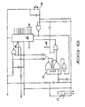
- FIG. 1 shows a typical system which comprises heat-fusion pipe fitting 10, coding tab 11, heating element terminals 12 and 13, power control unit 20, power supply 21, optical head 22, control circuit connecting means 23 and power leads 24 and 25.
- connecting means can be used. For example, with light emitting diodes and phototransistors located in the optical head electrically conductive wire can be used. If the light source and sensors are remote from the optical head, optical fibers capable of transmitting the light can be used.
- Fig. 2 is a cross-sectional view of the heat-fusion pipe fitting 10 of Fig. 1.
- Heating element 14 consisting of electrical heating wire is in a spiral configuration and embedded within the thermoplastic body portion of the fitting 10.
- the heating element 14 is connected to the heating element terminals 12 and 13 which receive power from the power leads 24 and 25 shown in Fig. 1.
- Coding tab 11 has slots 15 which permit the passage of optical signals from within the optical head 22.
- Fig. 3 is a cross-sectional view of pipe fitting 10 taken through the coding tab portion of the pipe fitting 10.
- the optical head 22 contains a series of uniformly spaced infra-red light emitting diodes 16 and photo-transistors 17 spaced in the same configuration as the diodes but on the opposite side of the coding tab 11.
- Light emitting diodes such as Texas TIL 24 and photo transistors such as Texas L5600 have been found to be readily adaptable for this type of application.
- the optical coupling path for the infra-red light is from the light emitting diodes 16 through slots 15 and to the photo-transistors 17.
- each transistor is held to an "on or off” state depending on the excitation if received from the light emitting diodes through the presence or absence of slots. In this manner electrically coded signals are transmitted to the power control unit 20 through the return portion of control connecting means 23.
- Fig. 4 is an electrical schematic diagram for the signal circuit showing the circuit positions of the light emitting diodes 16 and of the photo-transistors 17.
- the diodes are powered with 0-5 volts and are constantly in the transmit mode. These diodes thus emit light whenever the circuit is energized.
- Corresponding photo-transistors which are positioned as previously described receive excitation from the diodes if there is a slot in the coding tab between the diode and the transistor.
- the collector of these photo-transistors are in a high, 5 volt, state or a low, 0 volt, state depending on the optical path existing to the diode.
- An 8-bit digital code at circuit point 30 is transmitted to the control unit decoder input shown in Fig. 5.
- Fig. 5 shows a typical decode circuit which can be used in the apparatus of this invention.
- the 8- bit digital code is buffered through a series of sixteen Schmitt invertors 31.
- the recognition code for the heat-fusion pipe fitting electrical heating elements 14 is defined by the arrangement of links to the 8 input NOR gates 32. Three such NOR gates are shown for defining three fusion times such as 90, 150 and 220 seconds.
- NOR gates Three such NOR gates are shown for defining three fusion times such as 90, 150 and 220 seconds.
- Fig. 6 shows the control circuit for the fusion timing control ICM chip 7217 36, for example, converts the binary coded decimal code to a suitable signal for output to a light emitting diode display (digit segments) and stores the appropriate code in a count register.
- the fusion cycle which controls the time for which the heat-fusion pipe fitting electrical heating element is energized is initiated by depressing the fusion push button 37 to change the R-S latch condition which starts the fusion time countdown. This time countdown is also displayed by the light emitting diodes on a control box.
- a signal from the ICM chip 36 at location 38 (typically identified as pin 2 on an ICM 7217 chip)causes the termination of the fusion cycle in the countactor circuit and resets the R-S latch.
- the circuit also includes reset push switch 39; fault signal 40 and R-S latch 41.
- the advantages of the pipe fitting and control system of this invention include (1) no metal-to- metal contact resistance to overcome in signal detection: (2) continuous self-checking when the power unit is not connected to a pipe fitting: (3) sensing element in the control circuit can be hermetically sealed; (4) simplified pipe fitting manufacturing process; (5) a minimum of "add- to" cost and complexity to the pipe fitting since all of the electrical control means are in the control unit separate from the pipe fitting; (6) slot combination potentials which permit coding for hundreds of power application intervals; and (7) the adaptability of the system for use in controlling the fusion impressed voltage and fusion current as well as the fusion time.
Description
- The invention relates to a thermoplastic heat-fusion pipe fitting system comprising a thermoplastic heat-fusion pipe fitting having a body portion to accommodate a pipe and means bearing a code in which an array of apertures is formed which are indicative of the amount of heat required to effect the fusion of the fitting, means for heating said fitting associated with the fitting, means for sensing and decoding the code and control means responsive to information decoded from the code for regulating the amount of heat applied by the heating means to the fitting.
- Thermoplastic heat-fusion pipe fittings have long been used to join thermoplastic pipe members. There are many designs for such fittings, which tend to fall into three basic types: (1) those having an electrical heating element which is embedded within the body of the fitting and located in close proximity to the surface of the fitting that is to be joined to the pipe member by heat fusion, for an example, as disclosed in US-A-3,432,179; (2) a metal core embedded in the body of the fitting in which eddy currents can be induced by the action of an induction coil thereby producing a heating effect in the core; and (3) those which are meant to be heated by the application of an external heat source.
- Each design of heat-fusion pipe fitting requires a special amount of heat to be delivered to it to effect fusion of the fitting to a pipe member. For example, each variation in the design of an electrical heating element used in a type (1) heat-fusion pipe fitting changes its electrical characteristics, and thus the amount of power developed in the heating element to produce sufficient heat to effect fusion. Since most of these pipe fittings are installed in a trench, this variation in heat requirements can cause problems in field installation and often necessitates using labor having a greater degree of skill than is normally required for installing thermoplastic pipe lines and pipe line replacement sections.
- In order to simplify installation of type (1) pipe fittings, US-A-3,465,126 discloses a power unit for use in thermal welding of thermoplastic pipe sections. This power unit would be used to supply the energy to the electrical heating element under controlled conditions as to voltage and duration of power application. Predetermined levels of output voltage and power application are set prior to the use of the power unit in the field. However, this type of procedure does not make allowances for field use of different types of fittings on the same job site.
- EP-A-0 076 043 discloses a type (1) electro fusion pipe fitting having incorporated therein an identity resistor. This resistor would have a value dependent on the energy to be dissipated by the electrical heating element within the fitting. This fitting would be used in conjunction with control apparatus that would sense the characteristics of the identity resistor and use this information to automatically control the power applied to the electro fusion fitting. However, the fitting employed in this system is more difficult to manufacture than one having an electrical heating element alone, because of the addition of the identity resistor and its associated wiring and terminals.
- GB-A-2,119,744 discloses a type (1) heat-fusion pipe fitting system wherein the code bearing means are integral with the electrical terminal posts of the fitting and rely on magnetic flux flowing through one or more metal arms. Apertures in the metal arms form the code and cause leakage of the magnetic flux. The pattern of the magnetic flux leakage is detected by a Hall-effect probe. The reliability of this system is limited because the flux field can be disturbed by metal objects located in the neighborhood of the fitting.
- The invention as claimed in
claim 1 solves the problem of how to improve the reliability of a thermoplastic heat-fusion pipe fitting system by direct detection of the apertures in the code bearing means. - Preferred embodiments of the invention are set forth in the subclaims.
- One way of carrying out the invention is described in detail below with reference to drawings, in which:
- Fig. 1. is a schematic view of a heat-fusion pipe fitting and control system of the present invention.
- Fig. 2 is a cross-sectional view of the pipe fitting of Fig. 1.
- Fig. 3 is a cross-sectional view of the pipe fitting of Fig. 1. taken through the shaped portion bearing the code.
- Fig. 4 is a schematic drawing of a photo/electric aperture sensing circuit which can be used with the pipe fitting of Fig. 1.
- Fig. 5 is a schematic drawing of a decode circuit which can be used in the present invention.
- Fig. 6 is a schematic drawing of a control circuit which can be used in the present invention.
- The present invention provides an apparatus and system for forming fusion welds in thermoplastic pipes so that they can be used in pressurized applications such as in water and gas distribution systems. The heating means can be an electrical heating element integral with the fitting an induction coil and a metal core integral with the fitting or a non-integral heating member such as a heated plate, for application to a surface of the fitting.
- The shaped portion bearing a code is preferably integrally molded with the body portion of the fitting and, most preferably, bears a digital code. This shaped portion can lie flush to the surface of the fitting or, preferably, constitutes a tab standing out from the fitting. It has been found to be particularly convenient to provide this shaped code-bearing portion in the form of a tab mounted directly onto the pipe fittings. This coding tab has no electrical association with the heating element of the fitting but is used in the control system of an associated power supply apparatus for controlling the duration of the voltage applied to the terminals of the fitting. The coding tab contains holes or slots arranged in a predetermined sequence for use with a light detecting control system. The holes or slots are arranged to pass or stop infra-red light in optically-coupled paths in a prearranged sequence which generates an electrical signal that is indicative of the characteristics of the heating element of the fitting. This signal is converted in a control circuit to a control signal which regulates the duration of the voltage applied to the power terminals of the fitting. As an alternative to apertures or slots in the coding area a wide variety of means can be used to indicate the code, such as a row of stippling either on the surface of the fitting or on a tab projecting from the fitting, or by means of a tab having areas of reduced thickness instead of apertures or slots.
- The control means can control the amount of heat supplied to the fitting either by regulating the time for which the heating means is activated by regulating the electrical power supply to the heating means by controlling the voltage or current applied to the heating means.
- The sensing means can take a wide variety of forms depending on the physical form in which the code is expressed. For example, if the code is expressed as an array of apertures in a projecting tab the sensing means can comprise at least one signal generating means for translating signals through the apertures and the corresponding number of signal detecting means located so as to detect the signals passing through the apertures. The signal generating means can be, for example, a source of electrical magnetic radiation particularly a source of infrared or white light, a sound generator, a gas emitter and the like, with signal detecting means responsive to the type of signal generated.
- It is also preferred that the shaped portion be releasably connectable to the sensing and decoding means. For instance, the sensing means can be located in a head which is designed to fit over the shaped portion when the shaped portion is a projecting tab.
- A typical apparatus of the present invention is more fully illustrated in the drawings. Fig. 1 shows a typical system which comprises heat-
fusion pipe fitting 10, coding tab 11,heating element terminals power control unit 20,power supply 21,optical head 22, controlcircuit connecting means 23 and power leads 24 and 25. A wide variety of connecting means can be used. For example, with light emitting diodes and phototransistors located in the optical head electrically conductive wire can be used. If the light source and sensors are remote from the optical head, optical fibers capable of transmitting the light can be used. - Fig. 2 is a cross-sectional view of the heat-
fusion pipe fitting 10 of Fig. 1.Heating element 14 consisting of electrical heating wire is in a spiral configuration and embedded within the thermoplastic body portion of thefitting 10. Theheating element 14 is connected to theheating element terminals slots 15 which permit the passage of optical signals from within theoptical head 22. - Fig. 3 is a cross-sectional view of pipe fitting 10 taken through the coding tab portion of the pipe fitting 10. The
optical head 22 contains a series of uniformly spaced infra-redlight emitting diodes 16 and photo-transistors 17 spaced in the same configuration as the diodes but on the opposite side of the coding tab 11. Light emitting diodes such as Texas TIL 24 and photo transistors such as Texas L5600 have been found to be readily adaptable for this type of application. The optical coupling path for the infra-red light is from thelight emitting diodes 16 throughslots 15 and to the photo-transistors 17. By the predetermined selection of the arrangement ofslots 15 each transistor is held to an "on or off" state depending on the excitation if received from the light emitting diodes through the presence or absence of slots. In this manner electrically coded signals are transmitted to thepower control unit 20 through the return portion of control connecting means 23. - Fig. 4 is an electrical schematic diagram for the signal circuit showing the circuit positions of the
light emitting diodes 16 and of the photo-transistors 17. The diodes are powered with 0-5 volts and are constantly in the transmit mode. These diodes thus emit light whenever the circuit is energized. Corresponding photo-transistors which are positioned as previously described receive excitation from the diodes if there is a slot in the coding tab between the diode and the transistor. - The collector of these photo-transistors are in a high, 5 volt, state or a low, 0 volt, state depending on the optical path existing to the diode. An 8-bit digital code at
circuit point 30 is transmitted to the control unit decoder input shown in Fig. 5. - Fig. 5 shows a typical decode circuit which can be used in the apparatus of this invention. The 8- bit digital code is buffered through a series of sixteen
Schmitt invertors 31. The recognition code for the heat-fusion pipe fittingelectrical heating elements 14 is defined by the arrangement of links to the 8 input NORgates 32. Three such NOR gates are shown for defining three fusion times such as 90, 150 and 220 seconds. When a valid code is present at any 8 input NOR gate the relevant signals are transferred throughinverters 33 and 2-input NORgates 34 topins 35 on thecounter chip 36 shown in Fig. 6. These pins are typically designated on and ICM 7217 chip. - Fig. 6 shows the control circuit for the fusion timing control ICM chip 7217 36, for example, converts the binary coded decimal code to a suitable signal for output to a light emitting diode display (digit segments) and stores the appropriate code in a count register. The fusion cycle which controls the time for which the heat-fusion pipe fitting electrical heating element is energized is initiated by depressing the
fusion push button 37 to change the R-S latch condition which starts the fusion time countdown. This time countdown is also displayed by the light emitting diodes on a control box. When the count registers zero, a signal from theICM chip 36 at location 38 (typically identified aspin 2 on an ICM 7217 chip)causes the termination of the fusion cycle in the countactor circuit and resets the R-S latch. - The circuit also includes
reset push switch 39;fault signal 40 andR-S latch 41. - The advantages of the pipe fitting and control system of this invention include (1) no metal-to- metal contact resistance to overcome in signal detection: (2) continuous self-checking when the power unit is not connected to a pipe fitting: (3) sensing element in the control circuit can be hermetically sealed; (4) simplified pipe fitting manufacturing process; (5) a minimum of "add- to" cost and complexity to the pipe fitting since all of the electrical control means are in the control unit separate from the pipe fitting; (6) slot combination potentials which permit coding for hundreds of power application intervals; and (7) the adaptability of the system for use in controlling the fusion impressed voltage and fusion current as well as the fusion time.
Claims (12)
Applications Claiming Priority (2)
| Application Number | Priority Date | Filing Date | Title |
|---|---|---|---|
| US06/696,198 US4571488A (en) | 1985-01-29 | 1985-01-29 | Heat-fusion pipe fitting system |
| US696198 | 1985-01-29 |
Publications (3)
| Publication Number | Publication Date |
|---|---|
| EP0189918A2 EP0189918A2 (en) | 1986-08-06 |
| EP0189918A3 EP0189918A3 (en) | 1987-06-24 |
| EP0189918B1 true EP0189918B1 (en) | 1990-01-31 |
Family
ID=24796099
Family Applications (1)
| Application Number | Title | Priority Date | Filing Date |
|---|---|---|---|
| EP19860101174 Expired - Lifetime EP0189918B1 (en) | 1985-01-29 | 1986-01-29 | Heat-fusion pipe fitting system |
Country Status (6)
| Country | Link |
|---|---|
| US (1) | US4571488A (en) |
| EP (1) | EP0189918B1 (en) |
| JP (1) | JPS61175022A (en) |
| CA (1) | CA1256663A (en) |
| DE (1) | DE3668579D1 (en) |
| IE (1) | IE57128B1 (en) |
Cited By (3)
| Publication number | Priority date | Publication date | Assignee | Title |
|---|---|---|---|---|
| US7943385B2 (en) | 2006-07-25 | 2011-05-17 | General Atomics | Methods for assaying percentage of glycated hemoglobin |
| US8318501B2 (en) | 2006-07-25 | 2012-11-27 | General Atomics | Methods for assaying percentage of glycated hemoglobin |
| US8673646B2 (en) | 2008-05-13 | 2014-03-18 | General Atomics | Electrochemical biosensor for direct determination of percentage of glycated hemoglobin |
Families Citing this family (31)
| Publication number | Priority date | Publication date | Assignee | Title |
|---|---|---|---|---|
| US4695335A (en) * | 1985-11-08 | 1987-09-22 | R. W. Lyall & Company, Inc. | Method for developing a predetermined fusing temperature in thermoplastic items |
| US4684789A (en) * | 1986-04-17 | 1987-08-04 | Central Plastics Company | Thermoplastic fitting electric welding method and apparatus |
| JPH0745185B2 (en) * | 1986-12-24 | 1995-05-17 | 積水化学工業株式会社 | Electric welding equipment |
| US4852914A (en) * | 1987-06-19 | 1989-08-01 | Milfuse Systems, Inc. | Plastic pipeline having rapidly fusible joints and method of making same |
| JPH0536669Y2 (en) * | 1987-10-22 | 1993-09-16 | ||
| DE3810795C2 (en) * | 1988-03-30 | 1994-04-21 | Huerner Gmbh | Electric welding machine for automatic welding of heating coil fittings |
| US4943706A (en) * | 1988-04-18 | 1990-07-24 | R. W. Lyall & Company, Inc. | Method and apparatus for fusing thermoplastic materials |
| CH675391A5 (en) * | 1988-07-04 | 1990-09-28 | Fischer Ag Georg | |
| GB8818521D0 (en) * | 1988-08-04 | 1988-09-07 | Du Pont Uk | Heat fusion pipe fitting system |
| GB8910509D0 (en) * | 1989-05-08 | 1989-06-21 | British Gas Plc | Identification of electro-fusion fittings |
| EP0409226A3 (en) * | 1989-07-21 | 1993-01-13 | Hitachi, Ltd. | Power supply control system |
| US5170144A (en) * | 1989-07-31 | 1992-12-08 | Solatrol, Inc. | High efficiency, flux-path-switching, electromagnetic actuator |
| US5160396A (en) * | 1991-02-11 | 1992-11-03 | Engineering & Research Associates, Inc. | Low thermal inertia heater |
| US5208436A (en) * | 1991-04-12 | 1993-05-04 | The Lincoln Electric Company | Plasma torch with identification circuit |
| US5577528A (en) * | 1994-11-18 | 1996-11-26 | Southern California Gas Company | Apparatus for upgrade or repair of in-service pipelines |
| US5639394A (en) * | 1995-01-31 | 1997-06-17 | Kerotest Manufacturing Corp. | Electrofusion formed valve assembly |
| US5788789A (en) * | 1995-06-08 | 1998-08-04 | George Fischer Sloane, Inc. | Power device for fusing plastic pipe joints |
| CH691439A5 (en) * | 1996-03-28 | 2001-07-31 | Fischer G Rohrleitungssysteme Ag | Electric welding machine |
| DE19814249A1 (en) * | 1998-03-31 | 1999-10-07 | Matuschek Mestechnik Gmbh | Resistance welding device |
| JP3635062B2 (en) * | 1999-12-28 | 2005-03-30 | 東芝テック株式会社 | Electrophotographic fixing device |
| US6441352B1 (en) * | 2000-01-05 | 2002-08-27 | Ef Technologies, Inc. | Apparatus for electrically heat welding thermoplastic fittings and method of using the same |
| US6883835B2 (en) * | 2001-03-05 | 2005-04-26 | Basic Resources, Inc. | Polyfusion pipe repair system and method |
| US6870143B2 (en) * | 2002-04-18 | 2005-03-22 | Basic Resources, Inc. | System and method for encapsulating a pipe |
| FR2846110B1 (en) * | 2002-10-21 | 2005-01-28 | Hispano Suiza Sa | APPARATUS FOR READING IDENTIFICATION CONNECTORS |
| WO2007125572A1 (en) * | 2006-04-26 | 2007-11-08 | Nissan Diesel Motor Co., Ltd. | Heater component for pipe joint |
| US20080182442A1 (en) * | 2007-01-31 | 2008-07-31 | Jaeho Choi | Data Port for a Mobile Device |
| DE102007061483A1 (en) * | 2007-12-20 | 2009-07-02 | Erbe Elektromedizin Gmbh | Surgery Equipment connector system |
| US8424924B2 (en) * | 2008-09-19 | 2013-04-23 | Tas Acquisition Co., Llc | Electromagnetic bond welding of thermoplastic pipe distribution systems |
| GB2510145A (en) * | 2013-01-25 | 2014-07-30 | Radius Systems Ltd | An electrofusion fitting |
| PL3030876T3 (en) | 2013-08-08 | 2020-10-19 | Proper Pipe Ehf. | Pipe fittings allowing non-destructive pressure testing of integrity of seals |
| JP6804458B2 (en) * | 2015-02-06 | 2020-12-23 | メンコス,ルベン,アドルフォ | Electrical fusion fittings, methods and systems |
Family Cites Families (13)
| Publication number | Priority date | Publication date | Assignee | Title |
|---|---|---|---|---|
| NL236188A (en) * | 1958-02-17 | |||
| US3465126A (en) * | 1967-10-25 | 1969-09-02 | Susquehanna Corp | Power unit |
| US3789192A (en) * | 1972-09-01 | 1974-01-29 | Ppg Industries Inc | Electrically heated window with a temperature sensor |
| CS160721B1 (en) * | 1973-05-29 | 1975-05-04 | ||
| DE2601638A1 (en) * | 1976-01-17 | 1977-07-21 | Bosch Gmbh Robert | HANDLING MACHINE |
| DE2710998C2 (en) * | 1976-03-22 | 1984-08-02 | Sturm, Werner, 4614 Hägendorf | Thermoplastic sleeve with an electrical resistance heating wire |
| FR2411644A1 (en) * | 1977-12-16 | 1979-07-13 | Vickers Ltd | DOCUMENT HANDLING EQUIPMENT |
| US4253011A (en) * | 1979-12-13 | 1981-02-24 | Tempco Electric Heater Corporation | Plastic injection molding system having a temperature controlled electric heater element |
| DE3013398A1 (en) * | 1980-04-05 | 1981-10-08 | Brown, Boveri & Cie Ag, 6800 Mannheim | Production routing of flat components - uses bar coding label containing data directing component to production stages |
| DE3268829D1 (en) * | 1981-09-30 | 1986-03-13 | Fusion Plastics Ltd | Electro-fusion fitting |
| GB2119744A (en) * | 1982-05-11 | 1983-11-23 | British Gas Corp | Indicating devices for use with heat-sealable fittings for making connections to heat-sealable tubing or pipes |
| GB2151858B (en) * | 1983-12-16 | 1987-10-28 | British Gas Corp | Coupling including means for identifying heat-sealable fittings having a socket (8) |
| FR2572326B1 (en) * | 1984-10-31 | 1987-03-20 | Gaz De France | METHOD AND MACHINE FOR PRODUCING AUTOMATIC WELDING OF PLASTIC PARTS WITH INTEGRATED WINDING. |
-
1985
- 1985-01-29 US US06/696,198 patent/US4571488A/en not_active Expired - Lifetime
-
1986
- 1986-01-21 CA CA000499969A patent/CA1256663A/en not_active Expired
- 1986-01-27 IE IE223/86A patent/IE57128B1/en unknown
- 1986-01-28 JP JP61014918A patent/JPS61175022A/en active Granted
- 1986-01-29 EP EP19860101174 patent/EP0189918B1/en not_active Expired - Lifetime
- 1986-01-29 DE DE8686101174T patent/DE3668579D1/en not_active Expired - Lifetime
Cited By (5)
| Publication number | Priority date | Publication date | Assignee | Title |
|---|---|---|---|---|
| US7943385B2 (en) | 2006-07-25 | 2011-05-17 | General Atomics | Methods for assaying percentage of glycated hemoglobin |
| US8318501B2 (en) | 2006-07-25 | 2012-11-27 | General Atomics | Methods for assaying percentage of glycated hemoglobin |
| US8338184B2 (en) | 2006-07-25 | 2012-12-25 | General Atomics | Methods for assaying percentage of glycated hemoglobin |
| US8557591B2 (en) | 2006-07-25 | 2013-10-15 | General Atomics | Methods for assaying percentage of glycated hemoglobin |
| US8673646B2 (en) | 2008-05-13 | 2014-03-18 | General Atomics | Electrochemical biosensor for direct determination of percentage of glycated hemoglobin |
Also Published As
| Publication number | Publication date |
|---|---|
| IE57128B1 (en) | 1992-05-06 |
| US4571488A (en) | 1986-02-18 |
| EP0189918A3 (en) | 1987-06-24 |
| JPH0356662B2 (en) | 1991-08-28 |
| JPS61175022A (en) | 1986-08-06 |
| CA1256663A (en) | 1989-07-04 |
| DE3668579D1 (en) | 1990-03-08 |
| IE860223L (en) | 1986-07-29 |
| EP0189918A2 (en) | 1986-08-06 |
Similar Documents
| Publication | Publication Date | Title |
|---|---|---|
| EP0189918B1 (en) | Heat-fusion pipe fitting system | |
| GB8903223D0 (en) | Adjustable pipe bend with electrofusion facility | |
| KR960010850B1 (en) | Two-terminal multiplexible sensor | |
| CA2152551A1 (en) | Communication system and method | |
| DK0677210T3 (en) | Transmitting and receiving antenna with angled crossing elements | |
| US4764759A (en) | Open circuit detector for differential encoder feedback | |
| FI950112A0 (en) | Electrically weldable plastic part | |
| EP0353912B1 (en) | Heat fusion pipe fitting system | |
| US4639580A (en) | Coupling devices for use with electrofusion fittings of thermoplastic material | |
| CA1094202A (en) | Digital logic for condition responsive sensor | |
| US3842403A (en) | Optical remote control system | |
| GB2119744A (en) | Indicating devices for use with heat-sealable fittings for making connections to heat-sealable tubing or pipes | |
| JP2578104B2 (en) | Electric welding equipment | |
| EP0253868A1 (en) | Key operated switch | |
| JP3499395B2 (en) | Dwelling unit security equipment | |
| KR940001472Y1 (en) | Load-side abnormality detecting circuit of ac power supply | |
| JPH06341650A (en) | Electric stove | |
| AU636793B2 (en) | A circuit arrangement for control of a triac | |
| KR890000581Y1 (en) | Control circuit for detection of heater short line using neon lamp | |
| JPH029418Y2 (en) | ||
| CN1124475C (en) | Temperature detecting alarm system for high-voltage and ultrahigh-voltage switch contact | |
| GB2124438A (en) | Coupling including device for identifying heat-sealable fittings | |
| KR19990015320A (en) | Infrared alarm and its control method | |
| KR960000043Y1 (en) | Room temperature control circuit | |
| KR0111084Y1 (en) | Zerocrossing circuit of ac |
Legal Events
| Date | Code | Title | Description |
|---|---|---|---|
| PUAI | Public reference made under article 153(3) epc to a published international application that has entered the european phase |
Free format text: ORIGINAL CODE: 0009012 |
|
| AK | Designated contracting states |
Kind code of ref document: A2 Designated state(s): CH DE FR GB IT LI |
|
| PUAL | Search report despatched |
Free format text: ORIGINAL CODE: 0009013 |
|
| AK | Designated contracting states |
Kind code of ref document: A3 Designated state(s): CH DE FR GB IT LI |
|
| 17P | Request for examination filed |
Effective date: 19870709 |
|
| 17Q | First examination report despatched |
Effective date: 19880504 |
|
| GRAA | (expected) grant |
Free format text: ORIGINAL CODE: 0009210 |
|
| AK | Designated contracting states |
Kind code of ref document: B1 Designated state(s): CH DE FR GB IT LI |
|
| ITF | It: translation for a ep patent filed |
Owner name: ING. C. GREGORJ S.P.A. |
|
| REF | Corresponds to: |
Ref document number: 3668579 Country of ref document: DE Date of ref document: 19900308 |
|
| ET | Fr: translation filed | ||
| PLBE | No opposition filed within time limit |
Free format text: ORIGINAL CODE: 0009261 |
|
| STAA | Information on the status of an ep patent application or granted ep patent |
Free format text: STATUS: NO OPPOSITION FILED WITHIN TIME LIMIT |
|
| 26N | No opposition filed | ||
| ITTA | It: last paid annual fee | ||
| REG | Reference to a national code |
Ref country code: GB Ref legal event code: 732E |
|
| REG | Reference to a national code |
Ref country code: CH Ref legal event code: PUE Owner name: UPONOR B.V. |
|
| ITPR | It: changes in ownership of a european patent |
Owner name: CESSIONE;UPONOR B.V. |
|
| REG | Reference to a national code |
Ref country code: FR Ref legal event code: TP |
|
| PGFP | Annual fee paid to national office [announced via postgrant information from national office to epo] |
Ref country code: FR Payment date: 19991213 Year of fee payment: 15 |
|
| PGFP | Annual fee paid to national office [announced via postgrant information from national office to epo] |
Ref country code: GB Payment date: 19991217 Year of fee payment: 15 |
|
| PGFP | Annual fee paid to national office [announced via postgrant information from national office to epo] |
Ref country code: CH Payment date: 19991220 Year of fee payment: 15 |
|
| PGFP | Annual fee paid to national office [announced via postgrant information from national office to epo] |
Ref country code: DE Payment date: 19991227 Year of fee payment: 15 |
|
| PG25 | Lapsed in a contracting state [announced via postgrant information from national office to epo] |
Ref country code: GB Free format text: LAPSE BECAUSE OF NON-PAYMENT OF DUE FEES Effective date: 20010129 |
|
| PG25 | Lapsed in a contracting state [announced via postgrant information from national office to epo] |
Ref country code: LI Free format text: LAPSE BECAUSE OF NON-PAYMENT OF DUE FEES Effective date: 20010131 Ref country code: CH Free format text: LAPSE BECAUSE OF NON-PAYMENT OF DUE FEES Effective date: 20010131 |
|
| REG | Reference to a national code |
Ref country code: CH Ref legal event code: PL |
|
| GBPC | Gb: european patent ceased through non-payment of renewal fee |
Effective date: 20010129 |
|
| PG25 | Lapsed in a contracting state [announced via postgrant information from national office to epo] |
Ref country code: FR Free format text: LAPSE BECAUSE OF NON-PAYMENT OF DUE FEES Effective date: 20010928 |
|
| PG25 | Lapsed in a contracting state [announced via postgrant information from national office to epo] |
Ref country code: DE Free format text: LAPSE BECAUSE OF NON-PAYMENT OF DUE FEES Effective date: 20011101 |
|
| REG | Reference to a national code |
Ref country code: FR Ref legal event code: ST |
|
| PG25 | Lapsed in a contracting state [announced via postgrant information from national office to epo] |
Ref country code: IT Free format text: LAPSE BECAUSE OF NON-PAYMENT OF DUE FEES;WARNING: LAPSES OF ITALIAN PATENTS WITH EFFECTIVE DATE BEFORE 2007 MAY HAVE OCCURRED AT ANY TIME BEFORE 2007. THE CORRECT EFFECTIVE DATE MAY BE DIFFERENT FROM THE ONE RECORDED. Effective date: 20050129 |