EP0188663A2 - Tray for receiving and storing a rigid information disc and combination of such a tray with a storing cassette - Google Patents
Tray for receiving and storing a rigid information disc and combination of such a tray with a storing cassette Download PDFInfo
- Publication number
- EP0188663A2 EP0188663A2 EP85112438A EP85112438A EP0188663A2 EP 0188663 A2 EP0188663 A2 EP 0188663A2 EP 85112438 A EP85112438 A EP 85112438A EP 85112438 A EP85112438 A EP 85112438A EP 0188663 A2 EP0188663 A2 EP 0188663A2
- Authority
- EP
- European Patent Office
- Prior art keywords
- tray
- element according
- recess
- resilient
- handle bar
- Prior art date
- Legal status (The legal status is an assumption and is not a legal conclusion. Google has not performed a legal analysis and makes no representation as to the accuracy of the status listed.)
- Granted
Links
- 230000007246 mechanism Effects 0.000 claims description 12
- 239000004033 plastic Substances 0.000 claims description 12
- 229920003023 plastic Polymers 0.000 claims description 12
- 238000003780 insertion Methods 0.000 claims description 11
- 230000037431 insertion Effects 0.000 claims description 11
- 238000002347 injection Methods 0.000 claims description 4
- 239000007924 injection Substances 0.000 claims description 4
- 230000003993 interaction Effects 0.000 claims description 2
- 239000002184 metal Substances 0.000 claims description 2
- 239000004417 polycarbonate Substances 0.000 claims description 2
- 229920000515 polycarbonate Polymers 0.000 claims description 2
- 238000013461 design Methods 0.000 description 6
- 230000008901 benefit Effects 0.000 description 3
- 238000010276 construction Methods 0.000 description 2
- 239000000463 material Substances 0.000 description 2
- 230000002950 deficient Effects 0.000 description 1
- 238000006073 displacement reaction Methods 0.000 description 1
- 230000009977 dual effect Effects 0.000 description 1
- 238000007765 extrusion coating Methods 0.000 description 1
- 230000014759 maintenance of location Effects 0.000 description 1
- 238000000034 method Methods 0.000 description 1
- 239000000203 mixture Substances 0.000 description 1
- 230000008569 process Effects 0.000 description 1
- 239000000243 solution Substances 0.000 description 1
- 238000005507 spraying Methods 0.000 description 1
- 238000012549 training Methods 0.000 description 1
- 238000012546 transfer Methods 0.000 description 1
Images


Classifications
-
- G—PHYSICS
- G11—INFORMATION STORAGE
- G11B—INFORMATION STORAGE BASED ON RELATIVE MOVEMENT BETWEEN RECORD CARRIER AND TRANSDUCER
- G11B23/00—Record carriers not specific to the method of recording or reproducing; Accessories, e.g. containers, specially adapted for co-operation with the recording or reproducing apparatus ; Intermediate mediums; Apparatus or processes specially adapted for their manufacture
- G11B23/02—Containers; Storing means both adapted to cooperate with the recording or reproducing means
- G11B23/03—Containers for flat record carriers
-
- G—PHYSICS
- G11—INFORMATION STORAGE
- G11B—INFORMATION STORAGE BASED ON RELATIVE MOVEMENT BETWEEN RECORD CARRIER AND TRANSDUCER
- G11B33/00—Constructional parts, details or accessories not provided for in the other groups of this subclass
- G11B33/02—Cabinets; Cases; Stands; Disposition of apparatus therein or thereon
- G11B33/04—Cabinets; Cases; Stands; Disposition of apparatus therein or thereon modified to store record carriers
- G11B33/0405—Cabinets; Cases; Stands; Disposition of apparatus therein or thereon modified to store record carriers for storing discs
- G11B33/0411—Single disc boxes
- G11B33/0422—Single disc boxes for discs without cartridge
-
- G—PHYSICS
- G11—INFORMATION STORAGE
- G11B—INFORMATION STORAGE BASED ON RELATIVE MOVEMENT BETWEEN RECORD CARRIER AND TRANSDUCER
- G11B23/00—Record carriers not specific to the method of recording or reproducing; Accessories, e.g. containers, specially adapted for co-operation with the recording or reproducing apparatus ; Intermediate mediums; Apparatus or processes specially adapted for their manufacture
- G11B23/02—Containers; Storing means both adapted to cooperate with the recording or reproducing means
- G11B23/03—Containers for flat record carriers
- G11B23/032—Containers for flat record carriers for rigid discs
- G11B23/0321—Containers for flat record carriers for rigid discs rigid cartridges for single discs
-
- G—PHYSICS
- G11—INFORMATION STORAGE
- G11B—INFORMATION STORAGE BASED ON RELATIVE MOVEMENT BETWEEN RECORD CARRIER AND TRANSDUCER
- G11B23/00—Record carriers not specific to the method of recording or reproducing; Accessories, e.g. containers, specially adapted for co-operation with the recording or reproducing apparatus ; Intermediate mediums; Apparatus or processes specially adapted for their manufacture
- G11B23/02—Containers; Storing means both adapted to cooperate with the recording or reproducing means
- G11B23/03—Containers for flat record carriers
- G11B23/0328—Containers for flat record carriers the disc having to be extracted from the cartridge for recording reproducing, e.g. cooperating with an extractable tray
-
- Y—GENERAL TAGGING OF NEW TECHNOLOGICAL DEVELOPMENTS; GENERAL TAGGING OF CROSS-SECTIONAL TECHNOLOGIES SPANNING OVER SEVERAL SECTIONS OF THE IPC; TECHNICAL SUBJECTS COVERED BY FORMER USPC CROSS-REFERENCE ART COLLECTIONS [XRACs] AND DIGESTS
- Y10—TECHNICAL SUBJECTS COVERED BY FORMER USPC
- Y10S—TECHNICAL SUBJECTS COVERED BY FORMER USPC CROSS-REFERENCE ART COLLECTIONS [XRACs] AND DIGESTS
- Y10S206/00—Special receptacle or package
- Y10S206/804—Special receptacle or package with means to lift or draw out content
Definitions
- the invention relates to an element for receiving and holding a rigid circular information plate, consisting of a tray to be inserted into a storage cassette with a receiving tray and with brackets for fixing the information tray to be inserted into the receiving tray.
- the tray which is suitable as an easily removable insert for the storage cassette, is designed as a plug-in insert for a playback device, the holders, one of which is resilient, being arranged opposite one another on the edge of the receiving trough.
- the information plate By inserting the tray, the information plate lies in the storage cassette during storage in the tray.
- the tray When transferring to the playback device, only the tray needs to be grasped by hand and removed from the cassette.
- the information plate is transferred into the loading or unloading mechanism of the playback device with the tray.
- the tray thus has a dual function, namely the retention of the information plate during storage in the storage cassette and the contactless transfer of the information plate from the cassette to the playback device.
- brackets which are opposite each other at the edge of the receiving trough, the possibility is created that the loading or unloading mechanism when the tablet is inserted into the playback device releases the disk from the brackets and brings it into the playing position.
- the tray is provided on one side with a grip strip, in the area of which the resilient holder and the other, fixedly arranged holders are provided.
- the tray can be easily gripped by means of the handle and inserted into the loading or unloading mechanism.
- the resilient holder By means of the resilient holder, which can be pushed aside by the loading or unloading mechanism, the information plate is released during insertion.
- the tray is provided with a first recess, which is located in the region of the resilient holder.
- the resilient bracket can thus move easily during the insertion movement.
- the height of the tray is not increased because the resilient holder can be arranged in the area of the tray bottom.
- the first recess on the side of the receiving trough has an arcuate edge boundary which is approximately concentric with the center of the information to be introduced plate stretches.
- the information side of the plate is protected because the information side of the plate can only touch the tray with its outer edge during insertion into the tray. Furthermore, this design of the edge limitation results in stiffening the bottom of the receiving trough.
- the information page is also protected against finger contact from the underside of the floor pan.
- the arcuate boundary is interrupted by a recess drawn in towards the center, this recess being located opposite the resilient holder.
- the recess has the advantage that a pin of the loading or unloading mechanism can penetrate into the recess, push back the resilient holder and thus release the plate.
- a cam of the resilient bracket is arranged in the middle of a resilient bracket with its ends fastened to the handle bar and that the first recess extends over the entire width and depth of the resilient bracket.
- the resilient bracket is thus sufficiently elastic and can be made of plastic.
- the resilient bracket can be supported against spring means in its central region. Since the spring force of the resilient plastic bracket can weaken, e.g. B. at high temperatures, the resilient means ensure a adequate support or sufficient pushing back into the support position.
- the spring means are a spring bar clamped between its ends, which supports the resilient bracket and against which the resilient bracket is supported in the region of its cam.
- the spring bar protects against fatigue of the spring force of the plastic bracket as well as against negative temperature influences.
- the spring bar can be inserted later or embedded when the tray is sprayed.
- the resilient means are designed as spring lugs connected to the grip strip.
- Such spring lugs have the advantage that the tray and the resilient parts are all made of the same material.
- the resilient bracket is supported on the boundary of the first recess.
- the position of the cam on the resilient bracket is thus always precisely defined before the plate is received, so that the plate can always snap into place behind it.
- a second, U-shaped recess is provided in the bottom of the receiving trough, which has a goblet-shaped widening in the region of the fixed holders.
- the second recess has the purpose of exposing the disc opposite the turntable of the playback device.
- the cup-shaped expansion has there with the advantage that the writing or reading device of the device can move freely from parts of the tablet.
- the tray has guide strips that run perpendicular to the grip bar and that serve to guide the insertion for the interaction with a loading or unloading mechanism of the playback device.
- loading or unloading guides are introduced into the tray designed as a plastic injection-molded part. With such a design, other aids can also be readily arranged on the tray, which make loading and unloading easier.
- the invention also relates to a combination of a storage cassette consisting of a base and lid with such an element.
- a combination is characterized in that a Ausd Wegnocken is provided on the lid at least pushing up during the pivoting of the lid over more than 180 o the tray in the region of the handle bar from the bottom.
- a Ausd Wegnocken is provided on the lid at least pushing up during the pivoting of the lid over more than 180 o the tray in the region of the handle bar from the bottom.
- two push-out cams are provided which can be pressed against abutting edges on both ends of the handle bar. This training ensures that the handle bar is pressed up evenly on both sides. The tray cannot tilt when it is lifted.
- the handle bar has latching cams at both ends which engage in articulated openings of the storage cassette, which serve for the articulated mounting of the lid on the floor.
- the joint openings have a double function. On the one hand, they serve to pivot the lid and, on the other hand, they serve to receive the locking cams and thus to snap the tray into place.
- the latching cams are arranged on tabs provided elastically on the grip strip.
- the elastic design of the tabs makes it easier to take out and reinsert the tray into the receiving cassette.
- the abutting edges in the immediate vicinity of the tab are provided on the handle bar.
- the push-out cams come close to the locking cams. This is advantageous for pushing the tray out of the joint openings.
- protruding lugs are provided on the inner sides of bottom side walls, loading and unloading guides are movable for locking the tray on the side opposite the handle bar.
- the underside of the tray which is not secured by means of locking cams, is also secured against falling out.
- the side of the tray opposite the grip strip has an oblique edge. Such an inclined edge makes it easier to insert the tray into the bottom of the storage cassette.
- this tray 1 consists of a rectangular plate with a grip strip 2 (cf. also FIGS. 2, 3 and 4).
- the plate and handle are molded from plastic.
- the handle bar is preferably ribbed on its surface so that it can be gripped better.
- a receiving trough 3 which is arranged somewhat recessed and has a circumference which is somewhat larger than an information plate 4.
- the information plate is in this Embodiment a compact disc plate (a digital, optically readable audio plate).
- a first recess 5 is provided between the edge of the receiving trough 3 and the grip strip 2. This first recess 5 has a certain width.
- a resilient bracket 6 formed of plastic, which is preferably integrated into the tray. The ends of the resilient bracket 6 connect to the handle bar.
- a cam 7 serving as a holder is provided, which points in the direction of the center of the tray. Due to the elasticity of the resilient bracket, the cam 7 is pressed inwards. The elasticity of the resilient bracket 6 is supported by means of a spring bar 8 (see also FIG. 7).
- the spring bar 8 can be used later or can be embedded when spraying.
- insertion slots are preferably provided in the feet of the resilient bracket 6.
- 6 small retaining cams 9 are provided on the resilient bracket, with which the spring bar 8 can be positioned.
- the first recess 5 is delimited towards the receiving trough 3 by means of an arcuate border 5a. This edge delimitation 5a is approximately opaque with the plate edge.
- a recess 5b opposite the holder 7, which interrupts the arcuate border 5a.
- the recess 5b extends in the direction of the center of the tray and has an approximately rectangular contour. A pin of the loading mechanism of a playback device can engage in this recess 5b.
- the resilient support can also be done with the help of plastic spring tabs 10, which ge from the handle bar 2 ago press against the back of the resilient bracket 6.
- the spring lugs 10 are preferably injection molded together with the tray.
- Fig. 10 shows a further variant of the arrangement of the resilient bracket 6, wherein if no plate is received, the resilient bracket is pressed by the spring bar 8 against the arcuate edge boundary 5a, whereby the holder 7 is precisely positioned. After receiving the plate, the bracket 6 is preferably again free of the edge boundary 5a. 10, but also in the other configurations, it is advantageous if the top of the holder 7 has an oblique edge. This inclined edge is intended to facilitate the receiving of the plate 4 into the receiving tray 3 and the clamping behind the holder 7.
- Fig. Lla and llb show that the bracket 7 is alternatively provided in the central region of a leaf spring 6a.
- the leaf spring 6a is a metal spring and forms sufficient support for the plate even at higher temperatures.
- the bracket 7 is made of plastic and is molded or glued to the leaf spring.
- the holder 7 can also be provided in the central region of a wire spring 6b. It is advantageous here to design the spring 6b in the central region with a deflection 6c and to attach the holder by extrusion coating. Further, alternatively, a coil spring construction can be used instead of a leaf or wire spring in a manner not shown.
- a second recess 11 is provided, which is U-shaped and is widened at the ends on the side facing away from the handle bar.
- the tray is provided with a bridge 13 across the U-shaped recess on the side 12 opposite the handle strip 2.
- the bridge serves to improve the stability of the side 12.
- the bridge 13, as can be seen in FIG. 6, is somewhat higher than the bottom 14 of the receiving trough 3.
- the bridge 13 has a side edge 13a which extends upwards and with recesses 13b and 13c is provided.
- fixed brackets 15 and 16 are provided, which are arranged opposite the bottom 14 such that the plate 4 is clamped between the bottom 14 and the fixed brackets 15, 16.
- the fixed brackets 15, 16 are located in the region of the bridge 13. The design of the fixed brackets 15, 16 is shown enlarged in FIG. 5.
- Guide strips 17, 18 are provided in the area of the side edges 3a, 3b, which laterally delimit the tray.
- the guide strips 17, 18 are used to guide the insertion of the tray 1 into the loading or unloading mechanism of the playback device. Since the guide strips are provided on the underside of the tray 1, they prevent the tray from being inserted incorrectly into the loading or unloading mechanism.
- first loading or unloading guides 19 are provided, which represent interruptions of the guide strips 17, 18.
- the loading or unloading mechanism can engage in these first loading or unloading functions 19 and thus pull in or push out the tray.
- FIG. 7 shows, there is also a hook-shaped second loading or unloading guide 20 which serves a similar purpose.
- a third loading or unloading guide 21 is provided, which is designed like a heart curve.
- This third loading or unloading guide 21, which is additionally shown in section in FIG. 8, is preferably used to hold the tray in a collection receptacle, not shown, which works according to the printing-printing principle.
- Rack guides 22 are also provided, which run in the direction of insertion and can work together with wheels of an insert.
- tabs 25 are provided which project approximately perpendicularly from the handle bar. Since the tabs 25 protrude freely, they are somewhat flexible. On the tab 25 outwardly projecting locking cams 26 are provided (Fig. 3 and 7).
- This oblique edge 27 is intended to facilitate the insertion of the tray into a receiving cassette 28 (FIGS. 13 and 14).
- This receiving cassette 28 consists of a base 29 and a cover 30.
- the base 29 and cover 30 are pivotally connected to one another by means of a hinge 31.
- the hinge 31 consists of articulated openings 32 in the base part 29 and articulated pins 33 which engage in these openings 32 and which are provided on arms 30a of the cover.
- the locking cams 26 also engage in the hinge openings 32 of the base part, on the side facing away from the arms.
- the openings 32 thus have a double function, namely to lock the tray in the bottom 29 once and to hold the lid articulated on the bottom.
- the bottom side walls 34 are provided with lugs 35, under which the guide strips 17, 18 can grip.
- the tray 1 is thus also connected to the bottom 29 on the side remote from the grip strip 2. Lateral openings are also provided in the bottom side walls 34, which facilitate gripping the information plate 4.
- Squeeze cams 36 are provided on the inside of the arms 30a.
- the side walls 34 must be made somewhat thinner in the region of the openings 32 so that the push-out cams 36 are not hindered when pivoting.
- the push-out cams 36 press against abutting edges 2a of the handle bar 2 after swiveling over 1800, as a result of which the handle bar and thus the The tray is pushed up from the floor in the direction of an arrow A in FIG. 16.
- the pushing up takes place when the cover 30 is pivoted through an angle of more than 1800 according to arrow B in FIG. 16.
- the grip strip 2 can then be gripped easily by hand and can be removed from the bottom 29 with the tray 1.
- the guide strips 17, 18 pull out of the area of the lugs 35 when they are lifted up.
- the tray 1 is thus free.
- the tray After the tray with the plate 4 has been lifted out of the receiving cassette 28, the tray can be inserted into the loading or unloading mechanism. Here, the holder 7 is pushed back and the plate is exposed.
- the tray thus has a double function, namely for holding the information plate and at the same time as a loading aid for loading or unloading the plate in the playback device.
- the tray offers the possibility of replacing the insert that is present in a conventional recording cassette.
- the tray 1 preferably consists of a mixture of plastics, such as polycarbonate. This material gives the tray good stability.
- the trays according to the invention can be stacked by coordinating the geometry of the top and bottom of the trays.
- the oblique edge 27 of the first tray is adjacent to an oblique edge 2a of the handle 2 of the second tray after mutual displacement of the trays by 180 °.
- the side edge 13a of the second tray is inserted with the central part in the recess 5 of the first tray, while the insert lateral parts of the side edge 13a into elongated recesses 37 which, as shown in FIG. 7, are present on the bottom side of each tray. This prevents a mutual shift of the stacked trays.
Abstract
Description
Element zur Aufnahme und Halterung einer steifen kreisförmigen Informationsplatte sowie Kombination eines solchen Elementes mit einer AufbewahrungskassetteElement for receiving and holding a rigid circular information plate and combination of such an element with a storage cassette
Die Erfindung bezieht sich auf ein Element zur Aufnahme und Halterung einer steifen kreisförmigen Informationsplatte, bestehend aus einem in eine Aufbewahrungskassette einzubringenden Tablett mit einer Aufnahmewanne und mit Halterungen zum Fixieren der in die Aufnahmewanne einzubringenden Informationsplatte.The invention relates to an element for receiving and holding a rigid circular information plate, consisting of a tray to be inserted into a storage cassette with a receiving tray and with brackets for fixing the information tray to be inserted into the receiving tray.
Aus der EP-A-0 114 631 sind Elemente dieser Art bekannt, mit denen in einer Aufbewahrungskassette Informationsplatten aufbewahrt werden können. Solche Elemente bilden einen Einsatz für den Boden bzw. den Deckel der Aufbewahrungskassette, die, wie auch die Elemente selbst, als Kunststoffspritzgußteil ausgebildet sind. Die Elemente sind dabei aus dem Boden bzw. dem Deckel der Aufbewahrungskassette schwierig herausnehmbar; sie dienen damit nur dem Festhalten der Informationsplatte während der Aufbewahrung.From EP-A-0 114 631 elements of this type are known with which information plates can be stored in a storage cassette. Such elements form an insert for the bottom or the lid of the storage cassette, which, like the elements themselves, are designed as a plastic injection molded part. The elements are difficult to remove from the bottom or the lid of the storage cassette; they only serve to hold the information plate during storage.
Weiterhin ist es aus "Funkschau", 21/184, Seite 38, bekannt, für das berührungslose Handhaben von digitalen, optisch auslesbaren Audio-Platten (Compact-disc Platten) beim Laden bzw. Entladen von Audio-Spielern, von Halterungen Gebrauch zu machen, die U-förmig gestaltet sind und zwischen deren U-Schenkeln die zu handhabende Informationsplatte eingeklemmt ist. Für die Benutzung einer solchen, als Stecklade-Einschub zu bezeichnenden Halterung muß die Informationsplatte zunächst aus ihrer Aufbewahrungskassette herausgenommen und in die Halterung eingebracht werden. Die Handhabung einer CD-Platte mittels solch einer Halterung ohne Fingerberührung ist schwierig.Furthermore, from "Funkschau", 21/184, page 38, it is known to make use of holders for contactless handling of digital, optically readable audio disks (compact disc disks) when loading or unloading audio players , which are U-shaped and the information plate to be handled is clamped between their U-legs. For the use of such a holder, which can be called a plug-in drawer the information plate must first be removed from its storage cassette and inserted into the holder. The handling of a CD disc using such a holder without finger touch is difficult.
Es ist Aufgabe der Erfindung, für das Handhaben von Informationsplatten im Zusammenhang mit dem Laden und Entladen einer Abspieleinrichtung eine Lösung zu schaffen, die die Handhabung der Informationsplatte beim Überführen von der Aufbewahrungskassette in die Abspieleinrichtung erleichtert, wobei die Platte nicht berührt zu werden braucht.It is an object of the invention to provide a solution for handling information disks in connection with the loading and unloading of a playback device which facilitates the handling of the information disk when being transferred from the storage cassette into the playback device, the disk not needing to be touched.
Die gestellte Aufgabe ist erfindungsgemäß dadurch gelöst, daß das als leicht herausnehmbare Einlage für die Aufbewahrungskassette geeignete Tablett als Stecklade-Einschub für eine Abspieleinrichtung ausgebildet ist, wobei die Halterungen, von denen eine federnd ausgebildet ist, einander gegenüberliegend am Rand der Aufnahmewanne angeordnet sind.The stated object is achieved in that the tray, which is suitable as an easily removable insert for the storage cassette, is designed as a plug-in insert for a playback device, the holders, one of which is resilient, being arranged opposite one another on the edge of the receiving trough.
Durch die Einführung des Tabletts liegt die Informationsplatte während der Aufbewahrung im Tablett in der Aufbewahrungskassette. Beim Überführen in die Abspieleinrichtung braucht nur das Tablett mit der Hand erfaßt und aus der Kassette herausgenommen zu werden. Mit dem Tablett wird die Informationsplatte in den Lade- bzw. Entlademechanismus der Abspieleinrichtung überführt. Das Tablett hat damit eine doppelte Funktion, nämlich das Festhalten der Informationsplatte während der Aufbewahrung in der Aufbewahrungskassette und das berührungslose Überführen der Informationsplatte von der Kassette in die Abspieleinrichtung.By inserting the tray, the information plate lies in the storage cassette during storage in the tray. When transferring to the playback device, only the tray needs to be grasped by hand and removed from the cassette. The information plate is transferred into the loading or unloading mechanism of the playback device with the tray. The tray thus has a dual function, namely the retention of the information plate during storage in the storage cassette and the contactless transfer of the information plate from the cassette to the playback device.
Durch das Haltern der Informationsplatte mittels Halterungen, die einander am Rand der Aufnahmewanne gegenüberliegen, wird die Möglichkeit geschaffen, daß der Lade- bzw. Entlademechanismus beim Einschieben des Tablettes in die Abspieleinrichtung die Platte von den Halterungen löst und in die Spielstellung bringt.By holding the information plate by means of brackets, which are opposite each other at the edge of the receiving trough, the possibility is created that the loading or unloading mechanism when the tablet is inserted into the playback device releases the disk from the brackets and brings it into the playing position.
Nach einer weiteren Ausgestaltung der Erfindung ist vorgesehen, daß das Tablett an einer Seite mit einer Griffleiste versehen ist, in deren Bereich die federnde Halterung und der gegenüber die weiteren, fest angeordneten Halterungen vorgesehen sind. Mittels der Griffleiste läßt sich das Tablett leicht erfassen und in den Lade- bzw. Entlademechanismus einführen. Mittels der federnden Halterung, die vom Lade- bzw. Entlademechanismus beiseite geschoben werden kann, wird die Informationsplatte während des Einschiebens freigegeben.According to a further embodiment of the invention, it is provided that the tray is provided on one side with a grip strip, in the area of which the resilient holder and the other, fixedly arranged holders are provided. The tray can be easily gripped by means of the handle and inserted into the loading or unloading mechanism. By means of the resilient holder, which can be pushed aside by the loading or unloading mechanism, the information plate is released during insertion.
Nach einer weiteren Ausgestaltung der Erfindung ist vorgesehen, daß das Tablett mit einer ersten Ausnehmung versehen ist, die sich im Bereich der federnd ausgebildeten Halterung befindet. Die federnde Halterung kann sich dadurch während der Einschiebebewegung leicht bewegen. Die Bauhöhe des Tabletts wird nicht vergrößert, weil die federnde Halterung im Bereich des Tablettbodens angeordnet werden kann.According to a further embodiment of the invention, it is provided that the tray is provided with a first recess, which is located in the region of the resilient holder. The resilient bracket can thus move easily during the insertion movement. The height of the tray is not increased because the resilient holder can be arranged in the area of the tray bottom.
Nach einer weiteren Ausgestaltung der Erfindung ist vorgesehen, daß die erste Ausnehmung an der Seite der Aufnahmewanne eine bogenförmige Randbegrenzung hat, die sich etwa konzentrisch zur Mitte der einzubringenden Informationsplatte erstreckt. Die Informationsseite der Platte wird dabei geschützt, weil nämlich die Informationsseite der Platte während des Einschiebens in das Tablett nur mit ihrem äußeren Rand das Tablett berühren kann. Weiterhin hat diese Ausbildung der Randbegrenzung eine Versteifung des Bodens der Aufnahmewanne zur Folge. Die Informationsseite ist auch gegen eine Fingerberührung von der Unterseite der Bodenwanne her geschützt.According to a further embodiment of the invention, it is provided that the first recess on the side of the receiving trough has an arcuate edge boundary which is approximately concentric with the center of the information to be introduced plate stretches. The information side of the plate is protected because the information side of the plate can only touch the tray with its outer edge during insertion into the tray. Furthermore, this design of the edge limitation results in stiffening the bottom of the receiving trough. The information page is also protected against finger contact from the underside of the floor pan.
Nach einer weiteren Ausgestaltung der Erfindung ist vorgesehen, daß die bogenförmige Randbegrenzung durch eine zur Mitte eingezogene Aussparung unterbrochen ist, wobei sich diese Aussparung gegenüber der federnden Halterung befindet. Die Aussparung bringt den Vorteil, daß ein Stift des Lade- bzw. Entlademechanismus in die Aussparung eindringen, die federnde Halterung zurückdrücken und damit die Platte lösen kann.According to a further embodiment of the invention it is provided that the arcuate boundary is interrupted by a recess drawn in towards the center, this recess being located opposite the resilient holder. The recess has the advantage that a pin of the loading or unloading mechanism can penetrate into the recess, push back the resilient holder and thus release the plate.
Nach einer weiteren Ausgestaltung der Erfindung ist vorgesehen, daß ein Nocken der federnden Halterung in der Mitte eines mit seinen Enden an der Griffleiste befestigten federnden Bügels angeordnet ist und daß die erste Ausnehmung sich über die gesamte Breite und Tiefe des federnden Bügels hinaus erstreckt. Der federnde Bügel ist damit ausreichend elastisch und kann aus Kunststoff hergestellt sein.According to a further embodiment of the invention it is provided that a cam of the resilient bracket is arranged in the middle of a resilient bracket with its ends fastened to the handle bar and that the first recess extends over the entire width and depth of the resilient bracket. The resilient bracket is thus sufficiently elastic and can be made of plastic.
Nach einer weiteren Ausgestaltung der Erfindung ist vorgesehen, daß der federnde Bügel in seinem mittleren Bereich gegen Federmittel abstützbar ist. Da die Federkraft des federnden Kunststoffbügels erlahmen kann, z. B. bei hohen Temperaturen, sorgen die federnden Mittel für eine ausreichende Abstützung bzw. ein ausreichendes Zurückschieben in die Abstützstellung.According to a further embodiment of the invention it is provided that the resilient bracket can be supported against spring means in its central region. Since the spring force of the resilient plastic bracket can weaken, e.g. B. at high temperatures, the resilient means ensure a adequate support or sufficient pushing back into the support position.
Nach einer weiteren Ausgestaltung der Erfindung ist vorgesehen, daß die Federmittel ein zwischen seinen Enden eingespannter Federstab sind, der den federnden Bügel hinterlegt und gegen den sich der federnde Bügel im Bereich seines Nockens abstützt. Der Federstab schützt sowohl gegen eine Ermüdung der Federkraft des Kunststoffbügels als auch gegen negative Temperatureinflüsse. Der Federstab kann nachträglich eingefügt oder gleich beim Spritzen des Tabletts mit eingebettet werden.According to a further embodiment of the invention it is provided that the spring means are a spring bar clamped between its ends, which supports the resilient bracket and against which the resilient bracket is supported in the region of its cam. The spring bar protects against fatigue of the spring force of the plastic bracket as well as against negative temperature influences. The spring bar can be inserted later or embedded when the tray is sprayed.
Nach einer weiteren Ausgestaltung der Erfindung ist vorgesehen, daß die federnden Mittel als mit der Griffleiste verbundene Federnasen ausgebildet sind. Derartige Federnasen haben den Vorteil, daß das Tablett und die federnden Teile alle aus dem gleichen Material bestehen.According to a further embodiment of the invention it is provided that the resilient means are designed as spring lugs connected to the grip strip. Such spring lugs have the advantage that the tray and the resilient parts are all made of the same material.
Nach einer weiteren Ausgestaltung der Erfindung ist vorgesehen, daß sich der federnde Bügel an der Randbegrenzung der ersten Ausnehmung abstützt. Die Lage des Nockens am federnden Bügel ist damit vor der Aufnahme der Platte immer genau definiert, so daß die Platte hinter ihm immer gut einrasten kann.According to a further embodiment of the invention it is provided that the resilient bracket is supported on the boundary of the first recess. The position of the cam on the resilient bracket is thus always precisely defined before the plate is received, so that the plate can always snap into place behind it.
Nach einer weiteren Ausgestaltung der Erfindung ist vorgesehen, daß in dem Boden der Aufnahmewanne eine zweite, U-förmig gestaltete Ausnehmung vorgesehen ist, die im Bereich der fest angeordneten Halterungen eine kelchförmige Aufweitung aufweist. Die zweite Ausnehmung hat den Sinn, die Platte gegenüber dem Drehtisch der Abspieleinrichtung freizulegen. Die kelchförmige Aufweitung hat dabei den Vorteil, daß die Schreib- bzw. Leseeinrichtung der Einrichtung sich frei von Teilen des Tablettes bewegen kann.According to a further embodiment of the invention, it is provided that a second, U-shaped recess is provided in the bottom of the receiving trough, which has a goblet-shaped widening in the region of the fixed holders. The second recess has the purpose of exposing the disc opposite the turntable of the playback device. The cup-shaped expansion has there with the advantage that the writing or reading device of the device can move freely from parts of the tablet.
Nach einer weiteren Ausgestaltung der Erfindung ist vorgesehen, daß das Tablett senkrecht zur Griffleiste verlaufende Führungsleisten aufweist, die zur Einschubführung dienen für das Zusammenspiel mit einem Lade- bzw. Entlademechanismus der Abspieleinrichtung. Mit Hilfe der Führungsleisten wird einerseits eine einwandfreie Führung beim Einschieben in die Einrichtung gewährleistet, andererseits werden fehlerhafte Einschiebbewegungen, beispielsweise durch eine um 1800 gedrehte Position des Tabletts verhindert.According to a further embodiment of the invention, it is provided that the tray has guide strips that run perpendicular to the grip bar and that serve to guide the insertion for the interaction with a loading or unloading mechanism of the playback device. With the help of the guide strips a satisfactory guidance is ensured during insertion into the device on the one hand, on the other hand, defective Einschiebbewegungen, for example, prevented by a 180 0 turned position of the tray.
Nach einer weiteren Ausgestaltung der Erfindung ist vorgesehen, daß in das als Kunststoffspritzteil ausgebildete Tablett Lade- bzw. Entladeführungen eingebracht sind. Bei einer derartigen Ausbildung können ohne weiteres auch weitere Hilfsmittel am Tablett angeordnet werden, die das Laden und Entladen erleichtern.According to a further embodiment of the invention, it is provided that loading or unloading guides are introduced into the tray designed as a plastic injection-molded part. With such a design, other aids can also be readily arranged on the tray, which make loading and unloading easier.
Die Erfindung bezieht sich außer auf die besondere Ausbildung des Elementes auch auf eine Kombination einer aus Boden und Deckel bestehenden Aufbewahrungskassette mit einem derartigen Element. Nach einer weiteren Ausgestaltung der Erfindung ist eine derartige Kombination dadurch gekennzeichnet, daß auf dem Deckel wenigstens ein Ausdrücknocken vorgesehen ist, der beim Verschwenken des Deckels über mehr als 180o das Tablett im Bereich der Griffleiste vom Boden her hochdrückt. Beim Schwenken des Deckels um mehr als 1800 wird das Tablett im Bereich der Griffleiste automatisch hochgedrückt, womit die Griffleiste zum Anfassen frei wird. Dies ist wichtig im Hinblick auf die Aufgabe der Erfindung, nach der das Tablett sowohl beim Aufbewahren als auch beim Laden und Entladen der Platte einsetzbar sein soll.In addition to the special design of the element, the invention also relates to a combination of a storage cassette consisting of a base and lid with such an element. According to a further embodiment of the invention, such a combination is characterized in that a Ausdrücknocken is provided on the lid at least pushing up during the pivoting of the lid over more than 180 o the tray in the region of the handle bar from the bottom. When swiveling the lid more than 1800, the tray is in the area of Handle bar automatically pushed up, which frees the handle bar to touch. This is important in view of the object of the invention, according to which the tray should be usable both when storing and when loading and unloading the plate.
Nach einer weiteren Ausgestaltung der Erfindung ist vorgesehen, daß zwei Ausdrücknocken vorgesehen sind, die gegen Stoßkanten an beiden Enden der Griffleiste drückbar sind. Diese Ausbildung sichert, daß die Griffleiste an beiden Seiten gleichmäßig hochgedrückt wird. Das Tablett kann damit beim Anheben nicht verkanten.According to a further embodiment of the invention, it is provided that two push-out cams are provided which can be pressed against abutting edges on both ends of the handle bar. This training ensures that the handle bar is pressed up evenly on both sides. The tray cannot tilt when it is lifted.
Nach einer weiteren Ausgestaltung der Erfindung ist vorgesehen, daß die Griffleiste an beiden Enden Rastnocken aufweist, die in Gelenköffnungen der Aufbewahrungskassette eingreifen, die der gelenkigen Halterung des Deckels am Boden dienen. Den Gelenköffnungen kommt dabei eine doppelte Funktion zu. Zum einen dienen sie dem Schwenken des Deckels und zum anderen dienen sie dem Aufnehmen der Rastnocken und damit dem Einrasten des Tabletts.According to a further embodiment of the invention it is provided that the handle bar has latching cams at both ends which engage in articulated openings of the storage cassette, which serve for the articulated mounting of the lid on the floor. The joint openings have a double function. On the one hand, they serve to pivot the lid and, on the other hand, they serve to receive the locking cams and thus to snap the tray into place.
Nach einer weiteren Ausgestaltung der Erfindung ist vorgesehen, daß die Rastnocken an elastisch an der Griffleiste vorgesehenen Lappen angeordnet sind. Durch die elastische Ausbildung der Lappen wird das Herausnehmen, als auch wieder das Einführen des Tabletts in die Aufnahmekassette erleichtert.According to a further embodiment of the invention it is provided that the latching cams are arranged on tabs provided elastically on the grip strip. The elastic design of the tabs makes it easier to take out and reinsert the tray into the receiving cassette.
Nach einer weiteren Ausgestaltung der Erfindung ist vorgesehen, daß die Stoßkanten in unmittelbarer Nähe der Lappen an der Griffleiste vorgesehen sind. Die Ausdrücknocken kommen beim Verschwenken des Deckels damit gleich in die Nähe der Rastnocken. Dies ist vorteilhaft für das Herausdrücken des Tabletts aus den Gelenköffnungen.According to a further embodiment of the invention it is provided that the abutting edges in the immediate vicinity of the tab are provided on the handle bar. When the cover is swiveled, the push-out cams come close to the locking cams. This is advantageous for pushing the tray out of the joint openings.
Nach einer weiteren Ausgestaltung der Erfindung ist vorgesehen, daß an den Innenseiten von Bodenseitenwänden vorstehende Ansätze vorgesehen sind, Lade- bzw. Entladeführungen fahrbar sind zur Arretierung des Tabletts auf der der Griffleiste gegenüberliegenden Seite. Auch die nicht mittels Rastnocken gesicherte Seite des Tabletts ist durch diese Unterfahrfü'hrung gegen ein Herausfallen gesichert.According to a further embodiment of the invention it is provided that protruding lugs are provided on the inner sides of bottom side walls, loading and unloading guides are movable for locking the tray on the side opposite the handle bar. The underside of the tray, which is not secured by means of locking cams, is also secured against falling out.
Nach einer weiteren Ausgestaltung der Erfindung ist vorgesehen, daß die der Griffleiste gegenüberliegende Seite des Tabletts eine schräge Kante aufweist. Eine solche schräge Kante erleichtert das Einbringen des Tabletts in den Boden der Aufbewahrungskassette.According to a further embodiment of the invention, it is provided that the side of the tray opposite the grip strip has an oblique edge. Such an inclined edge makes it easier to insert the tray into the bottom of the storage cassette.
Die Erfindung wird anhand der Zeichnungen näher erläutert. Es zeigen:The invention is explained in more detail with reference to the drawings. Show it:
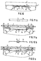
- Fig. 1 eine Draufsicht auf ein als Tablett ausgebildetes Element und eine in dasselbe aufgenommene Informationsplatte,1 is a plan view of an element designed as a tray and an information plate accommodated therein,
- Fig. 2 eine Ansicht des Elementes gemäß Pfeil II in Fig. 1,2 is a view of the element according to arrow II in Fig. 1,
- Fig. 3 eine Seitenansicht des Elementes gemäß dem Pfeil III in Fig. 1,3 shows a side view of the element according to arrow III in FIG. 1,
- Fig. 4 einen Schnitt durch das Element längs der Linie IV-IV nach Fig. 1,4 shows a section through the element along the line IV-IV according to FIG. 1,
- Fig. 5 in vergrößertem Maßstab einen Teil des Elementes gemäß Linie V-V in Fig. 1 im Schnitt,5 on an enlarged scale a part of the element according to line V-V in Fig. 1 in section,
- Fig. 6 eine Ansicht des Elementes in Richtung des Pfeiles VI in Fig. 1,6 is a view of the element in the direction of arrow VI in Fig. 1,
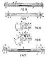
- Fig. 7 einen Draufsicht auf die Bodenseite des Elementes nach Fig. 1,7 is a plan view of the bottom side of the element of FIG. 1,
- Fig. 8 einen Schnitt durch das Element längs der Linie VIII-VIII in Fig. 7,8 shows a section through the element along the line VIII-VIII in FIG. 7,
- Fig. 9 eine Ansicht eines Teiles des Elementes in einer abgewandelten Ausführungsform,9 is a view of a part of the element in a modified embodiment,
- Fig. 10 eine Ansicht eines anders ausgebildeten Teiles des Elementes nach Fig. 1 ohne Informationsplatte,10 is a view of a differently formed part of the element of FIG. 1 without an information plate,
- Fig. lla eine Ansicht eines anders ausgebildeten Teiles des Elementes nach Fig. 1 ohne Informationsplatte,Lla is a view of a differently formed part of the element of FIG. 1 without an information plate,
- Fig. llb eine Ansicht eines federnden Bügels des Elementes nach Fig. lla,Llb is a view of a resilient bracket of the element of FIG. Lla,
- Fig. 12a eine Ansicht eines anders ausgebildeten Teiles des Elementes nach Fig. l ohne Informationsplatte,12a is a view of a differently designed part of the element according to FIG. 1 without an information plate,
- Fig. 12b eine Ansicht eines federnden Bügels des Elementes nach Fig. 12a,12b is a view of a resilient bracket of the element of FIG. 12a,
- Fig. 13 einen Schnitt durch eine Kombination aus einer Aufnahmekassette und einem in ihr aufgenommenen Tablett zur Aufnahme einer Informationsplatte,13 shows a section through a combination of a recording cassette and a tray accommodated therein for receiving an information plate,
- Fig. 14 eine Seitenansicht der Kombination nach Fig. 13,14 is a side view of the combination of FIG. 13,
- Fig. 15 einen Ausschnitt aus der Aufnahmekassette im Bereich des Scharnieres zwischen Boden und Deckel, wobei der Deckel um 1800 gegenüber dem Boden verschwenkt ist,15 shows a section of the receiving cassette in the area of the hinge between the base and the cover, the cover being pivoted by 180 ° relative to the base,
- Fig. 16 die Scharnierausbildung nach Fig. 15, wobei der Deckel gegenüber dem Boden um mehr als 1800 verschwenkt ist,Fig. 16, the hinge construction according to FIG. 15, with the cover over the surface of more than 180 is pivoted 0,
- Fig. 17 eine Seitenansicht einer Kombination aus zwei gestapelten Elementen nach Fig. 1.17 shows a side view of a combination of two stacked elements according to FIG. 1.
Wie die Draufsicht auf ein in Fig. 1 dargestelltes, als Tablett 1 ausgebildetes Element zeigt, besteht dieses Tablett 1 aus einer rechteckigen Platte mit einer Griffleiste 2 (vergl. auch Fig. 2, 3 und 4). Platte und Griffleiste sind aus Kunststoff gespritzt. Die Griffleiste ist vorzugsweise an ihrer Oberfläche gerippt, damit sie sich besser erfassen läßt. Dasselbe gilt für die Unterseite des Tabletts, insbesondere im Bereich der Griffleiste 2. Im Zentrum des Tabletts 1 ist eine Aufnahmewanne 3 vorgesehen, die etwas vertieft angeordnet ist und einen Umfang hat, der etwas größer ist als eine Informationsplatte 4. Die Informationsplatte ist in diesem Ausführungsbeispiel eine Compact-disc-Platte (eine digitale, optisch auslesbare Audioplatte). An den Seitenrändern 3a, 3b ist die Aufnahmewanne derart offen, daß der Rand der Informationsplatte mit der Hand leicht erfaßbar ist. Zwischen dem Rand der Aufnahmewanne 3 und der Griffleiste 2 ist eine erste Ausnehmung 5 vorgesehen. Diese erste Ausnehmung 5 hat eine bestimmte Breite. Innerhalb der ersten Ausnehmung 5 befindet sich ein aus Kunst toff gebildeter federnder Bügel 6, der vorzugsweise in das Tablett integriert ist. Die Enden des federnden Bügels 6 schließen an der Griffleiste an. In der Mitte des federnden Bügels ist ein als Halterung dienender Nocken 7 vorgesehen, der in Richtung auf das Zentrum des Tabletts weist. Durch die Elastizität des federnden Bügels wird der Nocken 7 nach innen gedrückt. Die Elastizität des federnden Bügels 6 wird unterstützt mittels eines Federstabes 8 (vergl. auch Fig. 7). Der Federstab 8 kann nachträglich eingesetzt werden oder beim Spritzen gleich mit eingebettet sein. Für das nachträgliche Einbringen des Federstabes 8 sind in den Füßen des federnden Bügels 6 vorzugsweise Einschubschlitze vorgesehen. Weiterhin sind am federnden Bügel 6 kleine Haltenocken 9 vorgesehen, mit denen der Federstab 8 positionierbar ist. Die erste Ausnehmung 5 ist zur Aufnahmewanne 3 hin begrenzt mittels einer bogenförmigen Randbegrenzung 5a. Diese Randbegrenzung 5a ist etwa deckend mit dem Plattenrand. In der Mitte der bogenförmigen Randbegrenzung 5a befindet sich gegenüber der Halterung 7 eine Aussparung 5b, die die bogenförmige Randbegrenzung 5a unterbricht. Die Aussparung 5b erstreckt sich in Richtung auf die Tablettmitte und hat eine etwa rechteckige Kontur. In diese Aussparung 5b kann ein Stift des Lademechanismus einer Abspieleinrichtung eingreifen.As the top view of an element shown in FIG. 1, designed as a
Wie alternativ in Fig. 9 dargestellt ist, kann die federnde Unterstützung auch mit Hilfe von Kunststoff-Federnasen 10 erfolgen, die von der Griffleiste 2 her gegen die Rückseite des federnden Bügels 6 drücken. Die Federnasen 10 sind vorzugsweise zusammen mit dem Tablett gespritzt.As shown alternatively in Fig. 9, the resilient support can also be done with the help of
Fig. 10 zeigt eine weitere Variante der Anordnung des federnden Bügels 6, wobei, wenn keine Platte aufgenommen ist, der federnde Bügel durch den Federstab 8 gegen die bogenförmige Randbegrenzung 5a gedrückt wird, wodurch die Halterung 7 genau positioniert ist. Nach Aufnahme der Platte liegt der Bügel 6 vorzugsweise wieder frei von der Randbegrenzung 5a. In der Ausbildung nach Fig. 10, aber auch in den anderen Ausbildungen, ist es vorteilhaft, wenn die Oberseite der Halterung 7 eine schräge Kante aufweist. Diese schräge Kante soll das Aufnehmen der Platte 4 in die Aufnahmewanna 3 und das Festklemmen hinter der Halterung 7 erleichtern.Fig. 10 shows a further variant of the arrangement of the
Fig. lla und llb zeigen, daß alternativ die Halterung 7 im mittleren Bereich einer Blattfeder 6a vorgesehen ist. Die Blattfeder 6a ist eine Metallfeder und bildet eine ausreichende Abstützung der Platte auch bei höheren Temperaturen. Die Halterung 7 besteht aus Kunststoff und ist an der Blattfeder gespritzt oder geklebt.Fig. Lla and llb show that the
Wie in den Fig. 12a und 12b dargestellt, kann die Halterung 7 auch im mittleren Bereich einer Drahtfeder 6b vorgesehen sein. Hierbei ist es vorteilhaft, die Feder 6b im mittleren Bereich mit einer Durchbiegung 6c auszuführen und durch Umspritzen die Halterung anzubringen. Weiter kann alternativ auf nicht dargestellte Weise eine Schraubenfeder-Konstruktion statt einer Blatt- oder Drahtfeder benutzt werden.As shown in FIGS. 12a and 12b, the
Im Bereich der Aufnahmewanne 3 ist eine zweite Ausnehmung 11 vorgesehen, die U-förmig gestaltet und auf der von der Griffleiste abliegenden Seite kelchförmig an ihren Enden aufgeweitet ist. Das Tablett ist über die U-förmige Ausnehmung hinweg auf der der Griffleiste 2 gegenüberliegenden Seite 12 mit einer Brücke 13 versehen. Die Brücke dient der Verbesserung der Stabilität der Seite 12. Die Brücke 13 liegt, wie sich aus Fig. 6 ergibt, etwas höher als der Boden 14 der Aufnahmewanne 3. Die Brücke 13 weist einen Seitenrand 13a auf, der sich aufwärts erstreckt und mit Aussparungen 13b und 13c versehen ist.In the area of the receiving trough 3, a
Im Bereich der Öffnung der Ausnehmung 11 sind feste Halterungen 15 und 16 vorgesehen, die derart gegenüber dem Boden 14 angeordnet sind, daß die Platte 4 zwischen dem Boden 14 und den festen Halterungen 15, 16 festgeklemmt wird. Die festen Halterungen 15, 16 befinden sich im Bereich der Brücke 13. Die Ausbildung der festen Halterungen 15, 16 ist vergrößert dargestellt in Fig. 5.In the area of the opening of the
Im Bereich der Seitenränder 3a, 3b sind Führungensleisten 17, 18 vorgesehen, die das Tablett seitlich begrenzen. Die Führungsleisten 17, 18 dienen der Einschubführung beim Einschieben des Tabletts 1 in den Lade- bzw. Entlademechanismus der Abspieleinrichtung. Da die Führungsleisten an der Unterseite des Tabletts 1 vorgesehen sind, verhindern sie ein fehlerhaftes Einschieben des Tabletts in den Lade- bzw. Entlademechanismus.Guide strips 17, 18 are provided in the area of the
Im Bereich der seitlichen Führungsleisten 17, 18 sind erste Lade- bzw. Entladeführungen 19 vorgesehen, die Unterbrechungen der Führungsleisten 17, 18 darstellen. Der Lade- bzw. Entlademechanismus kann in diese ersten Lade- bzw. Entladefunrungen 19 eingreifen und das Tablett damit einziehen bzw. herausstoßen. Wie Fig. 7 zeigt, gibt es weiterhin eine hakenförmige zweite Lade- bzw. Entladeführung 20, die einem ähnlichen Zweck dient. Gegenüber der hakenförmigen zweiten Lade- bzw. Entladeführung ist eine dritte Lade- bzw. Entladeführung 21 vorgesehen, die herzkurvenartig ausgebildet ist. Diese dritte Lade- bzw. Entladeführung 21, die in Fig. 8 zusätzlich noch im Schnitt dargestellt ist, dient vorzugsweise dazu, das Tablett in einer nicht dargestellten Sammelaufnahme festzuhalten, die nach dem Druck-druckprinzip arbeitet. Das bedeutet, daß das Tablett beim ersten Andruck verriegelt wird innerhalb der Sammelaufnahme und beim zweiten Drücken herausspringen kann. Weiterhin sind noch Zahnstangenführungen 22 vorgesehen, die in Einschubrichtung verlaufen und mit Rädern eines Einschubes zusammenarbeiten können. An der Bodenseite sind auch noch Positionierlöcher 23, 24 vorhanden. Das Positionierloch 23 ist dabei rund ausgebildet, während das Positionierloch 24 etwas länglich gestaltet ist. Mittels dieser Löcher kann das Tablett nach dem Ladevorgang in der Abspieleinrichtung sicher und genau positioniert werden.In the area of the lateral guide strips 17, 18 first loading or unloading guides 19 are provided, which represent interruptions of the guide strips 17, 18. The loading or unloading mechanism can engage in these first loading or unloading functions 19 and thus pull in or push out the tray. As FIG. 7 shows, there is also a hook-shaped second loading or unloading
An der Unterseite der Griffleiste 2 sind Lappen 25 vorgesehen, die etwa senkrecht von der Griffleiste abstehen. Da die Lappen 25 frei abstehen, sind sie etwas nachgiebig. An den Lappen 25 sind nach außen vorstehende Rastnocken 26 vorgesehen (Fig. 3 und 7).On the underside of the
An der der Griffleiste 2 gegenüberliegenden Seite 12 des Tabletts 1 ist, wie in Fig. 3 dargestellt, eine schräge Kante 27 vorgesehen. Diese schräge Kante 27 soll das Einschieben des Tabletts in eine Aufnahmekassette 28 erleichtern (Fig. 13 und 14). Diese Aufnahmekassette 28 besteht aus einem Boden 29 und einem Deckel 30. Boden 29 und Deckel 30 sind mittels eines Scharnieres 31 schwenkbar miteinander verbunden. Das Scharnier 31 besteht aus Gelenköffnungen 32 im Bodenteil 29 und in diese Öffnungen 32 eingegreifenden Gelenkstiften 33, die an Auslegern 30a des Deckels vorgesehen sind. Ebenso wie die Gelenkstifte 33 greifen auch die Rastnocken 26 in die Gelenköffnungen 32 des Bodenteiles ein, und zwar an der von den Auslegern abgewandten Seite. Die Öffnungen 32 haben damit eine doppelte Funktion, nämlich einmal das Tablett in dem Boden 29 zu verrasten und andererseits den Deckel gelenkig am Boden festzuhalten.On the
Die Bodenseitenwände 34 sind mit Ansätzen 35 versehen, unter die die Führungsleisten 17, 18 greifen können. Das Tablett 1 ist damit auch an der von der Griffleiste 2 abliegenden Seite mit dem Boden 29 verbunden. Auch in den Bodenseitenwänden 34 sind seitliche öffnungen vorgesehen, die das Ergreifen der Informationsplatte 4 erleichtern.The
Auf den Innenseiten der Ausleger 30a sind Ausdrücknocken 36 vorgesehen. Die Seitenwände 34 müssen im Bereich der Öffnungen 32 etwas dünner ausgebildet sein, damit die Ausdrücknocken 36 beim Schwenken nicht behindert werden. Wie in Fig. 15 dargestellt, drücken die Ausdrücknocken 36 nach einem Schwenken über 1800 gegen Stoßkanten 2a der Griffleiste 2, wodurch die Griffleiste und damit das Tablett aus dem Boden hochgedrückt wird in Richtung eines Pfeiles A in Fig. 16. Das Hochdrücken erfolgt bei einem Schwenken des Deckels 30 um einen Winkel von mehr als 1800 gemäß Pfeil B in Fig. 16. Die Griffleiste 2 kann dann leicht mit der Hand erfaßt und mit dem Tablett 1 aus dem Boden 29 herausgenommen werden. Die Führungsleisten 17, 18, ziehen sich beim Hochheben aus dem Bereich der Ansätze 35 heraus. Das Tablett 1 ist damit frei.
Nach dem Herausheben des Tabletts mit der Platte 4 aus der Aufnahmekassette 28 kann das Tablett in den Lade- bzw. Entlademechanismus eingeschoben werden. Hierbei wird die Halterung 7 zurückgedrückt, und die Platte wird freigelegt.After the tray with the
Das Tablett hat damit eine doppelte Funktion, nämlich für das Festhalten der Informationsplatte und gleichzeitig als Ladehilfe für das Laden bzw. Entladen der Platte in der Abspieleinrichtung. Das Tablett gibt die Möglichkeit, die in einer üblichen Aufnahmekassette vorhandene Einlage zu ersetzen. Vorzugsweise besteht das Tablett 1 aus einer Mischung aus Kunststoffen, wie Polykarbonat. Dieser Werkstoff gibt dem Tablett eine gute Stabilität.The tray thus has a double function, namely for holding the information plate and at the same time as a loading aid for loading or unloading the plate in the playback device. The tray offers the possibility of replacing the insert that is present in a conventional recording cassette. The
Die erfindungsgemässen Tabletts sind wie dargestellt in Fig. 17 stapelbar durch die Abstimmung der Geometrie von Ober- und Unterseite der Tabletts. Hierbei liegt die schräge Kante 27 des ersten Tabletts grenzend an einer schrägen Kante 2a der Griffleiste 2 des zweiten Tabletts nach gegenseitiger Versetzung der Tabletts um 180°. Der Seitenrand 13a des zweiten Tabletts steckt mit dem Mittenteil in der Ausnehmung 5 des ersten Tabletts, während die seitlichen Teile des Seitenrandes 13a in länglichen Aussparungen 37 stecken, die, wie in Fig. 7 dargestellt, an der Bodenseite jedes Tabletts vorhanden sind. Hierdurch ist eine gegenseitige Verschiebung der gestapelten Tabletts ausgeschloßen.As shown in FIG. 17, the trays according to the invention can be stacked by coordinating the geometry of the top and bottom of the trays. Here, the
Claims (23)
Applications Claiming Priority (2)
| Application Number | Priority Date | Filing Date | Title |
|---|---|---|---|
| DE3500323 | 1985-01-07 | ||
| DE3500323 | 1985-01-07 |
Related Child Applications (2)
| Application Number | Title | Priority Date | Filing Date |
|---|---|---|---|
| EP89200889A Division EP0330292A3 (en) | 1985-01-07 | 1985-10-02 | Combination of a storage cassette and an element for receiving and holding an information disc, and a storage cassette and element for receiving and holding for use in said combination |
| EP89200889.7 Division-Into | 1989-04-10 |
Publications (3)
| Publication Number | Publication Date |
|---|---|
| EP0188663A2 true EP0188663A2 (en) | 1986-07-30 |
| EP0188663A3 EP0188663A3 (en) | 1987-01-21 |
| EP0188663B1 EP0188663B1 (en) | 1991-01-16 |
Family
ID=6259376
Family Applications (2)
| Application Number | Title | Priority Date | Filing Date |
|---|---|---|---|
| EP89200889A Ceased EP0330292A3 (en) | 1985-01-07 | 1985-10-02 | Combination of a storage cassette and an element for receiving and holding an information disc, and a storage cassette and element for receiving and holding for use in said combination |
| EP85112438A Expired - Lifetime EP0188663B1 (en) | 1985-01-07 | 1985-10-02 | Tray for receiving and storing a rigid information disc and combination of such a tray with a storing cassette |
Family Applications Before (1)
| Application Number | Title | Priority Date | Filing Date |
|---|---|---|---|
| EP89200889A Ceased EP0330292A3 (en) | 1985-01-07 | 1985-10-02 | Combination of a storage cassette and an element for receiving and holding an information disc, and a storage cassette and element for receiving and holding for use in said combination |
Country Status (9)
| Country | Link |
|---|---|
| US (2) | US4722439A (en) |
| EP (2) | EP0330292A3 (en) |
| JP (1) | JPS61204879A (en) |
| KR (1) | KR910008173Y1 (en) |
| AT (1) | ATE60157T1 (en) |
| CA (1) | CA1249660A (en) |
| DE (1) | DE3581391D1 (en) |
| HK (1) | HK68192A (en) |
| SG (1) | SG80792G (en) |
Cited By (12)
| Publication number | Priority date | Publication date | Assignee | Title |
|---|---|---|---|---|
| EP0267644A1 (en) * | 1986-11-03 | 1988-05-18 | Koninklijke Philips Electronics N.V. | System for recording/reading information on/from a disc, comprising a disc cassette and an apparatus |
| DE8810917U1 (en) * | 1988-08-29 | 1989-01-12 | Dunker, Petra Christa Gretel, Geb. Rosema, 4030 Ratingen, De | |
| EP0302549A2 (en) * | 1987-08-03 | 1989-02-08 | Philips and Du Pont Optical Deutschland GmbH | Storing cassette for a disc-like information carrier |
| EP0315255A1 (en) * | 1987-11-02 | 1989-05-10 | Koninklijke Philips Electronics N.V. | Disc-record player comprising a disc-loading device for a disc supported on a tray |
| EP0384525A1 (en) * | 1989-02-23 | 1990-08-29 | Koninklijke Philips Electronics N.V. | Holder for an inscribable and/or readable disc |
| EP0515342A2 (en) * | 1991-05-23 | 1992-11-25 | Cartonneries De Thulin S.A. | Container for at least one disc with high information density |
| DE9215426U1 (en) * | 1992-11-12 | 1993-02-04 | Sun Hing Audio Equipment Mfy. Ltd., Kowloon, Hk | |
| BE1005321A4 (en) * | 1991-09-06 | 1993-06-29 | Thulin Cartonneries | Case for at least one high density information disc |
| EP0574107A1 (en) * | 1992-06-08 | 1993-12-15 | Risdon Corporation | Compact with pop-up tray operated by hinged cover |
| EP0608822A2 (en) * | 1993-01-27 | 1994-08-03 | Hans-Jürgen Luckow | CD-box with damping means |
| DE4302236A1 (en) * | 1993-01-27 | 1994-08-18 | Luckow Hans Juergen | CD case with clamping securement |
| US5913419A (en) * | 1995-05-29 | 1999-06-22 | U.S. Philips Corporation | Combination of a support for a disc-shaped recording medium and a holder for the support |
Families Citing this family (82)
| Publication number | Priority date | Publication date | Assignee | Title |
|---|---|---|---|---|
| EP0330292A3 (en) * | 1985-01-07 | 1990-03-28 | POLYGRAM GmbH | Combination of a storage cassette and an element for receiving and holding an information disc, and a storage cassette and element for receiving and holding for use in said combination |
| DE3712803C2 (en) * | 1987-04-15 | 1996-06-13 | Elba Buerosysteme Erich Kraut | Device for storing data disks in registry media |
| US4881640A (en) * | 1988-01-13 | 1989-11-21 | Reynard Cvc, Inc. | Article for storing optically readable and recordable disc devices |
| US4899875A (en) * | 1988-01-13 | 1990-02-13 | Reynard Cvc, Inc. | Article for storing optically readable and recordable disc devices |
| US4771883A (en) * | 1988-01-13 | 1988-09-20 | Reynard Cvc, Inc. | Article for storing digital laser disc devices |
| US4817079A (en) * | 1988-06-27 | 1989-03-28 | Eastman Kodak Company | Carrier retainer for disk cartridge |
| US4905217A (en) * | 1988-11-18 | 1990-02-27 | Simplicity Products, Inc. | Enclosure for optical disk or the like |
| US5086923A (en) * | 1988-10-24 | 1992-02-11 | Lakewood Industries, Inc. | Enclosure for optical disk or the like |
| DE3927380A1 (en) * | 1989-08-19 | 1991-02-21 | Philips & Du Pont Optical | STORAGE CASSETTE FOR A PLATE WITH A MEDIUM HOLE |
| US5383554A (en) * | 1991-06-11 | 1995-01-24 | Cowan; David M. | Container for storing and displaying an article |
| US5253751A (en) * | 1991-10-23 | 1993-10-19 | Sony Music Entertainment Inc. | Packaging for compact discs |
| CA2091979C (en) * | 1992-04-16 | 2002-08-13 | David L. Stumpff | Storage container for mini-disk cartridges |
| US5251750A (en) * | 1992-04-22 | 1993-10-12 | Paul J. Gelardi | Molded CD tray and pop up rosette therefor |
| GB9225970D0 (en) * | 1992-12-12 | 1993-02-10 | White Knight Prod Ltd | Compact disc package |
| DE9309103U1 (en) * | 1993-06-18 | 1993-08-12 | Cartonneries De Thulin S.A., Thulin, Be | |
| NO179848C (en) * | 1993-12-22 | 1996-12-27 | Dynoplast As | Cassette for CDs and similar objects |
| US5445265A (en) * | 1994-02-07 | 1995-08-29 | Reynard Cvc, Inc. | Storage container for information-bearing disc devices having printed matter retrieval means |
| DE9403885U1 (en) * | 1994-03-08 | 1994-05-19 | Naatz Joachim | Recording device for a disk-shaped data carrier |
| WO1995027281A2 (en) * | 1994-03-31 | 1995-10-12 | Philips Electronics Nv | Changer for information carriers, holder suitable for use in said changer, and scanning system comprising said holder |
| MY115952A (en) * | 1994-04-25 | 2003-10-31 | Sony Corp | Cd/cd-rom apparatus |
| US5533615A (en) * | 1994-12-30 | 1996-07-09 | Mccamy; William G. | Disc storage case |
| US5690218A (en) * | 1994-12-30 | 1997-11-25 | William Gary McCamy | Compact disc storage case |
| US5842563A (en) * | 1995-02-03 | 1998-12-01 | Laserfile International, Inc. | Storage container for information-bearing disc devices |
| US5768922A (en) * | 1995-03-03 | 1998-06-23 | Autronic Plastics, Inc. | Security case with field activated locking mechanism |
| USD379413S (en) * | 1995-06-07 | 1997-05-27 | Skaraborg Invest USA, Inc. | Disk-holding insert for a storage case for a compact disk |
| US5558220A (en) * | 1995-06-21 | 1996-09-24 | Owen J. Meegan | Case and tray for holding high density discs |
| US5730283A (en) * | 1995-07-03 | 1998-03-24 | Autronic Plastics, Inc. | Package and storage unit for digital information storage media |
| US5988376A (en) * | 1995-07-03 | 1999-11-23 | Autronics Plastics, Inc. | Security devices for information storage media with locking mechanisms |
| US6227364B1 (en) | 1995-12-21 | 2001-05-08 | William Collins | Disc package with retainment section |
| US5769216A (en) * | 1996-02-27 | 1998-06-23 | Collins; William | Holder for compact disc and the like |
| US6073763A (en) * | 1995-12-21 | 2000-06-13 | Collins; William | Holder for compact disc and the like |
| US5749463A (en) * | 1995-12-21 | 1998-05-12 | Collins; William | Compact disc pagkage with spines |
| US5957281A (en) * | 1995-12-21 | 1999-09-28 | Collins; William | Package for retaining both compact discs and computer discs |
| US5590768A (en) * | 1996-01-11 | 1997-01-07 | Compliant Solutions, Lc | Storage case for disk-shaped media having a bi-stable ejection mechanism utilizing compliant device technology |
| AU1825297A (en) * | 1996-01-11 | 1997-08-01 | Compliant Solutions, Lc | Disk-media storage case with ejection mechanism |
| US5816393A (en) * | 1996-05-24 | 1998-10-06 | Kim; Dong J. | CD storage module |
| TW396334B (en) * | 1996-07-12 | 2000-07-01 | Sony Corp | Disk tray and tray allocation box |
| CA2268664C (en) * | 1996-10-21 | 2005-03-15 | Marshall L. Weingarden | Storage container for information bearing disc devices |
| EP0855716A1 (en) * | 1997-01-25 | 1998-07-29 | Hans-Jürgen Luckow | CD box with holding means |
| US6137771A (en) * | 1997-04-09 | 2000-10-24 | Iomega Corporation | Shutterless data recording cartridge and drive for using same |
| DE19723503A1 (en) * | 1997-06-05 | 1998-12-10 | Philips Patentverwaltung | Two-part housing for receiving a plate-shaped information carrier |
| US5899327A (en) * | 1997-10-31 | 1999-05-04 | Ufe, Inc. | Protective storage case for digital discs, computer game cartridges and the like |
| EP0962934B1 (en) * | 1997-12-16 | 2003-06-04 | Matsushita Electric Industrial Co., Ltd. | Disk cartridge |
| US6598742B1 (en) | 1998-01-29 | 2003-07-29 | Nexpak Corporation | Lockable media storage box with lock and key |
| US6601701B1 (en) | 1998-01-29 | 2003-08-05 | Nexpak Corporation | Lockable media storage box with lock and key |
| US6672455B2 (en) * | 1998-01-29 | 2004-01-06 | Nexpak Corporation | Lockable media storage box with lock and key |
| JP3506598B2 (en) * | 1998-01-30 | 2004-03-15 | 松下電器産業株式会社 | Disk transfer mechanism |
| JP4143206B2 (en) * | 1998-03-09 | 2008-09-03 | 明晃化成工業株式会社 | Storage case for disk for recording media |
| US5996788A (en) * | 1998-04-01 | 1999-12-07 | Alpha Enterprises, Inc. | Storage container for recorded media |
| US6065594A (en) * | 1998-04-01 | 2000-05-23 | Alpha Enterprises, Inc. | Storage container for recorded media |
| US6093140A (en) * | 1998-11-23 | 2000-07-25 | Sagoma Plastics | Media storing tray-board mechanical attachment |
| KR100692770B1 (en) * | 1999-01-23 | 2007-03-09 | 엘지전자 주식회사 | Disc Cartridge and Method of The Same |
| USD426978S (en) * | 1999-03-05 | 2000-06-27 | Alpha Enterprises, Inc. | Hub for holding recorded media |
| USD426721S (en) * | 1999-03-05 | 2000-06-20 | Alpha Enterprises, Inc. | Tray for holding recorded media |
| USD430424S (en) * | 1999-03-05 | 2000-09-05 | Alpha Enterpriss, Inc. | Tray for holding recorded media |
| US6155417A (en) | 1999-03-26 | 2000-12-05 | Filam National Plastics | Disc storage container with retaining means |
| JP2003500308A (en) | 1999-05-31 | 2003-01-07 | デュアルボックス・リミテッド | Apparatus for holding disk-shaped articles |
| CA2378383A1 (en) * | 1999-07-08 | 2001-01-18 | John Joseph Lawlor | A storage case for a compact disc |
| GB9916996D0 (en) * | 1999-07-20 | 1999-09-22 | Price Robin J | Improvements in and relating to portable |
| US20060042330A1 (en) * | 1999-11-02 | 2006-03-02 | Autronic Plastics, Inc. | Storage case locking member |
| US7257971B2 (en) * | 2000-07-31 | 2007-08-21 | Autronics Plastics Inc. | Case with internal lock |
| US20030111367A1 (en) * | 2000-10-25 | 2003-06-19 | Michael Lax | Storage case |
| US6454090B1 (en) | 2000-05-18 | 2002-09-24 | Filam National Plastics | Disc storage container |
| AU2001288010A1 (en) * | 2000-09-11 | 2002-03-22 | Dualbox Limited | Improvements relating to a case for a disc-like article |
| JP3828734B2 (en) * | 2000-09-19 | 2006-10-04 | 株式会社 ネクサス | Disc case |
| EP1363288B8 (en) * | 2001-01-12 | 2009-08-12 | Panasonic Corporation | Disc cartridge |
| US6571944B2 (en) * | 2001-03-30 | 2003-06-03 | Sinta Technology Corp. | Fastening device for optical disc holder |
| JP3607880B2 (en) * | 2001-06-11 | 2005-01-05 | シナノケンシ株式会社 | Disk drive device |
| US20030000856A1 (en) * | 2001-06-27 | 2003-01-02 | Autronic Plastics, Inc. | Storage case |
| US6910219B2 (en) * | 2001-07-06 | 2005-06-21 | Matsushita Electric Industrial Co., Ltd. | Disc cartridge |
| US20030116454A1 (en) * | 2001-12-04 | 2003-06-26 | Marsilio Ronald M. | Lockable storage container for recorded media |
| TW588738U (en) * | 2002-04-03 | 2004-05-21 | Sinta Technology Corp | Optical disc carrier |
| US7610782B2 (en) * | 2003-02-07 | 2009-11-03 | Viva Onetime Limited | Lockable container having an integral and internal locking mechanism and methods of use |
| US8054194B2 (en) * | 2003-02-10 | 2011-11-08 | Autronic Plastics, Inc. | System and method for verifying a security status of a lockable container |
| WO2004088071A2 (en) * | 2003-03-26 | 2004-10-14 | Autronic Plastics, Inc. | Benefit denial systems for securing an asset within a container and methods of use |
| DE602004021801D1 (en) * | 2003-04-09 | 2009-08-13 | Panasonic Corp | DISC TRAY |
| HK1085351A2 (en) * | 2003-09-08 | 2006-08-18 | Glud & Marstarand As | A metal packaging |
| US20060108252A1 (en) * | 2004-10-11 | 2006-05-25 | Lax Michael R | Lockable container with merchandising features |
| US20070119730A1 (en) * | 2005-11-28 | 2007-05-31 | Mazyar Abolfazlian | Case with simplified access to compact disks or similar disks |
| US7726476B2 (en) * | 2006-04-06 | 2010-06-01 | Larry Dean Durham | Optical media storage package |
| TWI376686B (en) * | 2008-06-10 | 2012-11-11 | Pegatron Corp | Detachable drawer structure |
| EP2984000A4 (en) | 2013-04-08 | 2017-02-22 | Disc Graphics Inc. | Package and container assembly and method of manufacturing same |
Citations (13)
| Publication number | Priority date | Publication date | Assignee | Title |
|---|---|---|---|---|
| DE144596C (en) * | ||||
| US2550251A (en) * | 1947-08-20 | 1951-04-24 | Clarence D Hyatt | Record cabinet |
| US2848106A (en) * | 1956-12-21 | 1958-08-19 | Frederick H Rice | Container for phonograph record |
| FR1214192A (en) * | 1959-08-04 | 1960-04-07 | Thomson Houston Comp Francaise | Improvements to the sleeves containing the phonograph records |
| DE1103045B (en) * | 1959-03-25 | 1961-03-23 | Rudolf Wittner | Container for storing records |
| FR2437672A1 (en) * | 1978-09-27 | 1980-04-25 | Matsushita Electric Ind Co Ltd | ENCLOSURE FOR CONTAINING AT LEAST ONE RECORDING DISC AND DISC PLAYING SYSTEM |
| FR2474461A1 (en) * | 1979-12-21 | 1981-07-31 | Koehl Jean Marie | Gramophone storage and handling container - retains periphery of record between cover and base to clear grooves |
| FR2497992A1 (en) * | 1981-01-13 | 1982-07-16 | Thomson Brandt | Video disc holder - has disc support slidable into sleeve and carrying closure which locks support to prevent user access to disc |
| EP0112966A1 (en) * | 1982-12-23 | 1984-07-11 | idn inventions and development of novelties ag | Storage device for flat record carriers |
| EP0129292A1 (en) * | 1983-06-15 | 1984-12-27 | Koninklijke Philips Electronics N.V. | Disc-record player comprising a disc-loading mechanism and disc holder for use in such a player |
| FR2557346A1 (en) * | 1983-12-22 | 1985-06-28 | Staar Sa | Storage disc location and removal from carrier |
| EP0164788A1 (en) * | 1984-05-25 | 1985-12-18 | Koninklijke Philips Electronics N.V. | Holder for a rigid information disc and apparatus comprising a loading mechanism adapted to cooperate with such a holder |
| EP0170957A1 (en) * | 1984-07-23 | 1986-02-12 | Matsushita Electric Industrial Co., Ltd. | Disc accommodation tray and disc player employing said disc accommodation tray |
Family Cites Families (33)
| Publication number | Priority date | Publication date | Assignee | Title |
|---|---|---|---|---|
| GB190721009A (en) * | 1907-09-21 | 1907-12-19 | Wilhelm Borrmann | Receptacle for Keeping and Conveying Talking Machine Discs. |
| US2304307A (en) * | 1941-05-14 | 1942-12-08 | Gillette Safety Razor Co | Safety razor box |
| US2680512A (en) * | 1951-06-02 | 1954-06-08 | Douglas Young Inc | Display box |
| US3005541A (en) * | 1960-04-19 | 1961-10-24 | Custom Mfg Co | Display boxes for wrist watches and the like banded articles |
| DE1169694B (en) * | 1962-07-05 | 1964-05-06 | Friedrich Stuebbe | Record holder |
| US3140777A (en) * | 1963-01-28 | 1964-07-14 | Alvin C Gordan | Card case |
| US3232421A (en) * | 1963-01-30 | 1966-02-01 | Young Don Richard | Holder for tape reels |
| US3684123A (en) * | 1970-08-10 | 1972-08-15 | Aladdin Ind Inc | Stacked insulated cups |
| US3951264A (en) * | 1974-10-29 | 1976-04-20 | Dynastor, Inc. | Flexible disc cartridge |
| FR2324089A1 (en) * | 1975-09-11 | 1977-04-08 | Thomson Brandt | VIDEODISC CONTAINER |
| GR64982B (en) * | 1977-10-04 | 1980-06-11 | Palbox Spa | Reception(receiver)made of inflated thermoplastic material for the carrying out and storage of goods in bulk,for example agricultural products |
| US4239108A (en) * | 1979-11-28 | 1980-12-16 | Rca Corporation | Video disc caddy |
| US4266784A (en) * | 1979-11-28 | 1981-05-12 | Rca Corporation | Video disc caddy having disc entrapment |
| FR2477750A1 (en) * | 1980-03-07 | 1981-09-11 | Thomson Csf | CASSETTE FOR OPTICAL DISK |
| US4387807A (en) * | 1981-10-02 | 1983-06-14 | Rosa Jorge De | Ring cover protector for records |
| US4508217A (en) * | 1981-11-19 | 1985-04-02 | Innovative Concepts, Inc. | Storage container and display device |
| US4520470A (en) * | 1982-11-29 | 1985-05-28 | Staar S. A. | Cleaning device for discs |
| DE3301644A1 (en) * | 1983-01-19 | 1984-07-19 | Polygram Gmbh, 2000 Hamburg | STORAGE CASSETTE FOR TWO AND MORE DISK-SHAPED INFORMATION CARRIERS WITH HIGH STORAGE DENSITY |
| JPS59173182U (en) * | 1983-05-06 | 1984-11-19 | 松下電器産業株式会社 | disk jacket |
| US4463850A (en) * | 1983-05-10 | 1984-08-07 | Rca Corporation | Video disc caddy |
| US4463849A (en) * | 1983-05-23 | 1984-08-07 | Rca Corporation | Video disc caddy |
| US4707821A (en) * | 1983-11-08 | 1987-11-17 | U.S. Philips Corporation | Disc holder for a rigid audio and/or video disc |
| JPS60214485A (en) * | 1984-04-10 | 1985-10-26 | Matsushita Electric Ind Co Ltd | Recording disk container |
| KR910004048Y1 (en) * | 1984-04-13 | 1991-06-13 | 씨 비 에스 쏘니레코오드 가부시기가이샤 | Disc package |
| US4694448A (en) * | 1984-05-15 | 1987-09-15 | Nippon Gakki Seizo Kabushiki Kaisha | Disc case |
| US4538730A (en) * | 1984-05-18 | 1985-09-03 | Wu Chyi Ying | Collapsible storage box for floppy disk |
| JPS6132279A (en) * | 1984-07-23 | 1986-02-14 | Matsushita Electric Ind Co Ltd | Storage tray for disk |
| JPS6132280A (en) * | 1984-07-23 | 1986-02-14 | Matsushita Electric Ind Co Ltd | Storage tray for disk and player using tray |
| US4609105A (en) * | 1984-09-27 | 1986-09-02 | Storage Technology Partners Ii | Information recording disk cartridge protective structure |
| US4613044A (en) * | 1984-12-21 | 1986-09-23 | Nikkodo Co., Ltd. | Compact disc case |
| EP0330292A3 (en) * | 1985-01-07 | 1990-03-28 | POLYGRAM GmbH | Combination of a storage cassette and an element for receiving and holding an information disc, and a storage cassette and element for receiving and holding for use in said combination |
| US4714157A (en) * | 1985-07-18 | 1987-12-22 | Morrone James V | Media storage apparatus |
| US4702369A (en) * | 1986-01-31 | 1987-10-27 | Cinram Ltd./Ltee. | Storage container for records or the like |
-
1985
- 1985-10-02 EP EP89200889A patent/EP0330292A3/en not_active Ceased
- 1985-10-02 AT AT85112438T patent/ATE60157T1/en not_active IP Right Cessation
- 1985-10-02 EP EP85112438A patent/EP0188663B1/en not_active Expired - Lifetime
- 1985-10-02 DE DE8585112438T patent/DE3581391D1/en not_active Expired - Fee Related
-
1986
- 1986-01-02 CA CA000498876A patent/CA1249660A/en not_active Expired
- 1986-01-06 US US06/816,547 patent/US4722439A/en not_active Expired - Fee Related
- 1986-01-07 KR KR2019860000043U patent/KR910008173Y1/en not_active IP Right Cessation
- 1986-01-07 JP JP61000331A patent/JPS61204879A/en active Pending
-
1987
- 1987-10-16 US US07/109,806 patent/US4805770A/en not_active Expired - Fee Related
-
1992
- 1992-08-12 SG SG807/92A patent/SG80792G/en unknown
- 1992-09-10 HK HK681/92A patent/HK68192A/en unknown
Patent Citations (13)
| Publication number | Priority date | Publication date | Assignee | Title |
|---|---|---|---|---|
| DE144596C (en) * | ||||
| US2550251A (en) * | 1947-08-20 | 1951-04-24 | Clarence D Hyatt | Record cabinet |
| US2848106A (en) * | 1956-12-21 | 1958-08-19 | Frederick H Rice | Container for phonograph record |
| DE1103045B (en) * | 1959-03-25 | 1961-03-23 | Rudolf Wittner | Container for storing records |
| FR1214192A (en) * | 1959-08-04 | 1960-04-07 | Thomson Houston Comp Francaise | Improvements to the sleeves containing the phonograph records |
| FR2437672A1 (en) * | 1978-09-27 | 1980-04-25 | Matsushita Electric Ind Co Ltd | ENCLOSURE FOR CONTAINING AT LEAST ONE RECORDING DISC AND DISC PLAYING SYSTEM |
| FR2474461A1 (en) * | 1979-12-21 | 1981-07-31 | Koehl Jean Marie | Gramophone storage and handling container - retains periphery of record between cover and base to clear grooves |
| FR2497992A1 (en) * | 1981-01-13 | 1982-07-16 | Thomson Brandt | Video disc holder - has disc support slidable into sleeve and carrying closure which locks support to prevent user access to disc |
| EP0112966A1 (en) * | 1982-12-23 | 1984-07-11 | idn inventions and development of novelties ag | Storage device for flat record carriers |
| EP0129292A1 (en) * | 1983-06-15 | 1984-12-27 | Koninklijke Philips Electronics N.V. | Disc-record player comprising a disc-loading mechanism and disc holder for use in such a player |
| FR2557346A1 (en) * | 1983-12-22 | 1985-06-28 | Staar Sa | Storage disc location and removal from carrier |
| EP0164788A1 (en) * | 1984-05-25 | 1985-12-18 | Koninklijke Philips Electronics N.V. | Holder for a rigid information disc and apparatus comprising a loading mechanism adapted to cooperate with such a holder |
| EP0170957A1 (en) * | 1984-07-23 | 1986-02-12 | Matsushita Electric Industrial Co., Ltd. | Disc accommodation tray and disc player employing said disc accommodation tray |
Non-Patent Citations (1)
| Title |
|---|
| FUNKSCHAU, Nr. 21, 12. Oktober 1984, Seite 38; Munchen, DE T. KNOLL: "CD im Auto: Mobilisierung." * |
Cited By (18)
| Publication number | Priority date | Publication date | Assignee | Title |
|---|---|---|---|---|
| EP0267644A1 (en) * | 1986-11-03 | 1988-05-18 | Koninklijke Philips Electronics N.V. | System for recording/reading information on/from a disc, comprising a disc cassette and an apparatus |
| EP0302549A2 (en) * | 1987-08-03 | 1989-02-08 | Philips and Du Pont Optical Deutschland GmbH | Storing cassette for a disc-like information carrier |
| EP0302549A3 (en) * | 1987-08-03 | 1990-03-07 | Philips and Du Pont Optical Deutschland GmbH | Storing cassette for a disc-like information carrier |
| EP0315255A1 (en) * | 1987-11-02 | 1989-05-10 | Koninklijke Philips Electronics N.V. | Disc-record player comprising a disc-loading device for a disc supported on a tray |
| DE8810917U1 (en) * | 1988-08-29 | 1989-01-12 | Dunker, Petra Christa Gretel, Geb. Rosema, 4030 Ratingen, De | |
| EP0384525A1 (en) * | 1989-02-23 | 1990-08-29 | Koninklijke Philips Electronics N.V. | Holder for an inscribable and/or readable disc |
| EP0515342A3 (en) * | 1991-05-23 | 1993-05-12 | Cartonneries De Thulin S.A. | Container for at least one disc with high information density |
| EP0515342A2 (en) * | 1991-05-23 | 1992-11-25 | Cartonneries De Thulin S.A. | Container for at least one disc with high information density |
| US5244085A (en) * | 1991-05-23 | 1993-09-14 | Cartonneries De Thulin | Casing for at least one high density data disk |
| BE1005321A4 (en) * | 1991-09-06 | 1993-06-29 | Thulin Cartonneries | Case for at least one high density information disc |
| EP0574107A1 (en) * | 1992-06-08 | 1993-12-15 | Risdon Corporation | Compact with pop-up tray operated by hinged cover |
| DE9215426U1 (en) * | 1992-11-12 | 1993-02-04 | Sun Hing Audio Equipment Mfy. Ltd., Kowloon, Hk | |
| EP0608822A2 (en) * | 1993-01-27 | 1994-08-03 | Hans-Jürgen Luckow | CD-box with damping means |
| DE4302236A1 (en) * | 1993-01-27 | 1994-08-18 | Luckow Hans Juergen | CD case with clamping securement |
| EP0608822A3 (en) * | 1993-01-27 | 1994-08-31 | Hans-Jürgen Luckow | CD-box with damping means |
| US5450951A (en) * | 1993-01-27 | 1995-09-19 | Luckow; Hans-Juergen | Compact disc case with holding clamp |
| US5522501A (en) * | 1993-01-27 | 1996-06-04 | Luckow; Hans-Juergen | Compact disc case with a holding clamp |
| US5913419A (en) * | 1995-05-29 | 1999-06-22 | U.S. Philips Corporation | Combination of a support for a disc-shaped recording medium and a holder for the support |
Also Published As
| Publication number | Publication date |
|---|---|
| EP0188663A3 (en) | 1987-01-21 |
| EP0330292A3 (en) | 1990-03-28 |
| JPS61204879A (en) | 1986-09-10 |
| EP0330292A2 (en) | 1989-08-30 |
| US4722439A (en) | 1988-02-02 |
| SG80792G (en) | 1992-12-04 |
| KR910008173Y1 (en) | 1991-10-12 |
| US4805770A (en) | 1989-02-21 |
| ATE60157T1 (en) | 1991-02-15 |
| CA1249660A (en) | 1989-01-31 |
| HK68192A (en) | 1992-09-18 |
| DE3581391D1 (en) | 1991-02-21 |
| KR860010078U (en) | 1986-08-16 |
| EP0188663B1 (en) | 1991-01-16 |
Similar Documents
| Publication | Publication Date | Title |
|---|---|---|
| EP0188663B1 (en) | Tray for receiving and storing a rigid information disc and combination of such a tray with a storing cassette | |
| EP0430956B1 (en) | Storage case for circular data carriers | |
| DE2640890C2 (en) | Container for the protective storage and automatic handling of a video disc | |
| DE69733030T2 (en) | FOLDING BOX FOR DATA PLATE | |
| DE2558849C2 (en) | container | |
| DE3521913C2 (en) | ||
| DE69727847T2 (en) | Cartridge housing for disc-shaped record carrier and disc cartridge | |
| EP0198434A2 (en) | Process and device for the storage of flat record carriers | |
| EP0207111A1 (en) | Container for phono records or video discs. | |
| EP0302549A2 (en) | Storing cassette for a disc-like information carrier | |
| EP0112436A1 (en) | Device for storing flat record carriers | |
| EP0671743B1 (en) | Holding device for disc-type data carrier | |
| DE3713389C2 (en) | Magnetic storage and data recovery device | |
| DE3222844A1 (en) | DISK CARTRIDGE | |
| EP0439483A1 (en) | A record player. | |
| DE3712803A1 (en) | DEVICE FOR KEEPING DATA DISKETTE IN FOLDER | |
| DE2908262C2 (en) | ||
| DE2336443B2 (en) | MAGNETIC TAPE CASSETTE DEVICE | |
| DE3142831A1 (en) | MAGNETIC TAPE CASSETTE | |
| DE2453154A1 (en) | DEVICE FOR LOADING DISCS WITH CASES INTO A RECORDING AND PLAYBACK DEVICE | |
| DE3943564C2 (en) | Record player with integrated disc changer | |
| DE8519649U1 (en) | Cassette cover with a number of compartments to hold one magnetic tape cassette each | |
| EP1012844B1 (en) | Device for storing disk-shaped audio and/or data media | |
| DE4120968C2 (en) | ||
| DE602004007495T2 (en) | PLATE HOLDER |
Legal Events
| Date | Code | Title | Description |
|---|---|---|---|
| PUAI | Public reference made under article 153(3) epc to a published international application that has entered the european phase |
Free format text: ORIGINAL CODE: 0009012 |
|
| AK | Designated contracting states |
Kind code of ref document: A2 Designated state(s): AT BE CH DE FR GB IT LI LU NL SE |
|
| PUAL | Search report despatched |
Free format text: ORIGINAL CODE: 0009013 |
|
| AK | Designated contracting states |
Kind code of ref document: A3 Designated state(s): AT BE CH DE FR GB IT LI LU NL SE |
|
| 17P | Request for examination filed |
Effective date: 19870623 |
|
| 17Q | First examination report despatched |
Effective date: 19881121 |
|
| GRAA | (expected) grant |
Free format text: ORIGINAL CODE: 0009210 |
|
| AK | Designated contracting states |
Kind code of ref document: B1 Designated state(s): AT BE CH DE FR GB IT LI LU NL SE |
|
| REF | Corresponds to: |
Ref document number: 60157 Country of ref document: AT Date of ref document: 19910215 Kind code of ref document: T |
|
| XX | Miscellaneous (additional remarks) |
Free format text: TEILANMELDUNG 89200889.7 EINGEREICHT AM 02/10/85. |
|
| REF | Corresponds to: |
Ref document number: 3581391 Country of ref document: DE Date of ref document: 19910221 |
|
| ITF | It: translation for a ep patent filed |
Owner name: ING. C. GREGORJ S.P.A. |
|
| ET | Fr: translation filed | ||
| GBT | Gb: translation of ep patent filed (gb section 77(6)(a)/1977) | ||
| PLBE | No opposition filed within time limit |
Free format text: ORIGINAL CODE: 0009261 |
|
| STAA | Information on the status of an ep patent application or granted ep patent |
Free format text: STATUS: NO OPPOSITION FILED WITHIN TIME LIMIT |
|
| 26N | No opposition filed | ||
| PGFP | Annual fee paid to national office [announced via postgrant information from national office to epo] |
Ref country code: GB Payment date: 19921001 Year of fee payment: 8 |
|
| PGFP | Annual fee paid to national office [announced via postgrant information from national office to epo] |
Ref country code: LU Payment date: 19921014 Year of fee payment: 8 |
|
| PGFP | Annual fee paid to national office [announced via postgrant information from national office to epo] |
Ref country code: AT Payment date: 19921020 Year of fee payment: 8 |
|
| PGFP | Annual fee paid to national office [announced via postgrant information from national office to epo] |
Ref country code: FR Payment date: 19921021 Year of fee payment: 8 |
|
| PGFP | Annual fee paid to national office [announced via postgrant information from national office to epo] |
Ref country code: SE Payment date: 19921028 Year of fee payment: 8 |
|
| PGFP | Annual fee paid to national office [announced via postgrant information from national office to epo] |
Ref country code: BE Payment date: 19921029 Year of fee payment: 8 |
|
| PGFP | Annual fee paid to national office [announced via postgrant information from national office to epo] |
Ref country code: NL Payment date: 19921031 Year of fee payment: 8 |
|
| PGFP | Annual fee paid to national office [announced via postgrant information from national office to epo] |
Ref country code: DE Payment date: 19921229 Year of fee payment: 8 |
|
| PGFP | Annual fee paid to national office [announced via postgrant information from national office to epo] |
Ref country code: CH Payment date: 19930120 Year of fee payment: 8 |
|
| EPTA | Lu: last paid annual fee | ||
| PG25 | Lapsed in a contracting state [announced via postgrant information from national office to epo] |
Ref country code: LU Free format text: LAPSE BECAUSE OF NON-PAYMENT OF DUE FEES Effective date: 19931002 Ref country code: GB Effective date: 19931002 Ref country code: AT Effective date: 19931002 |
|
| PG25 | Lapsed in a contracting state [announced via postgrant information from national office to epo] |
Ref country code: SE Effective date: 19931003 |
|
| PG25 | Lapsed in a contracting state [announced via postgrant information from national office to epo] |
Ref country code: LI Effective date: 19931031 Ref country code: CH Effective date: 19931031 Ref country code: BE Effective date: 19931031 |
|
| BERE | Be: lapsed |
Owner name: POLYGRAM INTERNATIONAL HOLDING B.V. Effective date: 19931031 |
|
| PG25 | Lapsed in a contracting state [announced via postgrant information from national office to epo] |
Ref country code: NL Effective date: 19940501 |
|
| GBPC | Gb: european patent ceased through non-payment of renewal fee |
Effective date: 19931002 |
|
| NLV4 | Nl: lapsed or anulled due to non-payment of the annual fee | ||
| PG25 | Lapsed in a contracting state [announced via postgrant information from national office to epo] |
Ref country code: FR Effective date: 19940630 |
|
| REG | Reference to a national code |
Ref country code: CH Ref legal event code: PL |
|
| PG25 | Lapsed in a contracting state [announced via postgrant information from national office to epo] |
Ref country code: DE Effective date: 19940701 |
|
| REG | Reference to a national code |
Ref country code: FR Ref legal event code: ST |
|
| EUG | Se: european patent has lapsed |
Ref document number: 85112438.8 Effective date: 19940510 |