EP0188193A2 - Method and apparatus for processing image data - Google Patents
Method and apparatus for processing image data Download PDFInfo
- Publication number
- EP0188193A2 EP0188193A2 EP86100035A EP86100035A EP0188193A2 EP 0188193 A2 EP0188193 A2 EP 0188193A2 EP 86100035 A EP86100035 A EP 86100035A EP 86100035 A EP86100035 A EP 86100035A EP 0188193 A2 EP0188193 A2 EP 0188193A2
- Authority
- EP
- European Patent Office
- Prior art keywords
- image
- image data
- background
- dynamic range
- value
- Prior art date
- Legal status (The legal status is an assumption and is not a legal conclusion. Google has not performed a legal analysis and makes no representation as to the accuracy of the status listed.)
- Withdrawn
Links
- 238000000034 method Methods 0.000 title claims abstract description 51
- 238000012545 processing Methods 0.000 title claims abstract description 19
- 238000003705 background correction Methods 0.000 claims abstract description 23
- 238000007906 compression Methods 0.000 claims abstract description 8
- 230000006835 compression Effects 0.000 claims abstract description 8
- 238000013139 quantization Methods 0.000 claims abstract description 7
- 238000001914 filtration Methods 0.000 claims abstract description 4
- 238000012935 Averaging Methods 0.000 claims description 3
- 238000012360 testing method Methods 0.000 claims 1
- WJCNZQLZVWNLKY-UHFFFAOYSA-N thiabendazole Chemical compound S1C=NC(C=2NC3=CC=CC=C3N=2)=C1 WJCNZQLZVWNLKY-UHFFFAOYSA-N 0.000 description 17
- 238000012937 correction Methods 0.000 description 16
- 210000001550 testis Anatomy 0.000 description 16
- 230000006870 function Effects 0.000 description 13
- 238000010586 diagram Methods 0.000 description 11
- 239000011159 matrix material Substances 0.000 description 8
- 238000013519 translation Methods 0.000 description 4
- 238000009499 grossing Methods 0.000 description 3
- 238000004458 analytical method Methods 0.000 description 2
- 230000005540 biological transmission Effects 0.000 description 2
- 239000003086 colorant Substances 0.000 description 2
- 239000002131 composite material Substances 0.000 description 2
- 230000003068 static effect Effects 0.000 description 2
- 101100328518 Caenorhabditis elegans cnt-1 gene Proteins 0.000 description 1
- 238000013144 data compression Methods 0.000 description 1
- 230000007812 deficiency Effects 0.000 description 1
- 238000012986 modification Methods 0.000 description 1
- 230000004048 modification Effects 0.000 description 1
- 230000000737 periodic effect Effects 0.000 description 1
- 238000003672 processing method Methods 0.000 description 1
- 230000008054 signal transmission Effects 0.000 description 1
Images


Classifications
-
- G06T5/92—
-
- G—PHYSICS
- G06—COMPUTING; CALCULATING OR COUNTING
- G06T—IMAGE DATA PROCESSING OR GENERATION, IN GENERAL
- G06T5/00—Image enhancement or restoration
- G06T5/40—Image enhancement or restoration by the use of histogram techniques
-
- H—ELECTRICITY
- H04—ELECTRIC COMMUNICATION TECHNIQUE
- H04N—PICTORIAL COMMUNICATION, e.g. TELEVISION
- H04N1/00—Scanning, transmission or reproduction of documents or the like, e.g. facsimile transmission; Details thereof
- H04N1/40—Picture signal circuits
- H04N1/401—Compensating positionally unequal response of the pick-up or reproducing head
-
- H—ELECTRICITY
- H04—ELECTRIC COMMUNICATION TECHNIQUE
- H04N—PICTORIAL COMMUNICATION, e.g. TELEVISION
- H04N1/00—Scanning, transmission or reproduction of documents or the like, e.g. facsimile transmission; Details thereof
- H04N1/40—Picture signal circuits
- H04N1/407—Control or modification of tonal gradation or of extreme levels, e.g. background level
- H04N1/4072—Control or modification of tonal gradation or of extreme levels, e.g. background level dependent on the contents of the original
- H04N1/4074—Control or modification of tonal gradation or of extreme levels, e.g. background level dependent on the contents of the original using histograms
Abstract
Description
- The present invention relates to image data processing and more particularly to methods and apparatus for reducing objectionable background shading and noise in image data.
- The following are systems representative of the prior art.
- U.S. Patent 4,314,281 to Wiggins et al discloses inter alia a shading compensation system for scanning apparatus which includes a defocussed calibration strip which is scanned to provide shading signals for calibrating individual scanning elements of an array. The shading signals are processed in successive blocks each of which include a preset number of shading signals. Following processing, the shading signals are stored in memory and accessed during normal scanning. The shading signals are employed in operational modes to compensate the image signals produced by the scanner for deficiencies in scanning components.
- U. S. Patent 3,743,772 to Pieters et al shows a method and apparatus for correcting shading distortion in a scanned video signal. The shading correction according to the patent provides multiple location storage for storing a signal indicative of the shading correction required at each of a number of selected, spaced apart points in a scannable region of the source signal and signal interpolation means is provided for interpolating between the stored values of corrections in both line and frame scan directions for other points in a region.
- U. S. Patent 4,354,243 to Ryan et al teaches a shading error correction system in which correction signals are obtained during a first set up mode of the system which are then stored and interpolated and added to an image signal to provide a shading corrected image.
- U. S. Patent 4,251,831 to Kamath teaches a system for processing discrete digitized samples presenting composite signals utilizing a filter which eliminates a periodic signal component from the composite signal. The patent includes a color or shading correction circuit for dealing with a problem known as "drop out" in television signal transmission.
- U. S. Patent 4,326,258 to De LaGuardia shows a method and apparatus for reducing gray scale resolution of a document. The patent includes a high pass filter module for summing associated pixels within a window to produce a window sum as the window is moved along coordinates corresponding to the x and y axis and the high pass filter also includes means for comparing a selected pixels within a window with the associated window sum and predetermined criteria for generating first and second output values in accordance therewith.
- Although the patents cited relates generally to modification of image data, the patents does not show a method and apparatus such as is claimed herein including correcting the image for noise in the background by coring the image to achieve a single background gray scale value derived from image data for each background region in an image.
- The present invention is disclosed in the attached claims.
- It is an object of the present invention to process image data using gray scale techniques including means for obtaining a histogram of levels in an image; means for analyzing said histogram to identify one or more ranges of background in said image; means for converting each of said ranges of background to a constant value to achieve flat backgrounds in said image.
- It is another object of the present invention to process image data as above further including encoding said processed image using gray scale encoding techniques.
- It is yet another object of the present invention to process image data as above further including means for filtering all nonbackground pixels in said image.
- It is yet another object of the present invention to process image data as above further including means for generating for said image a shading correction for each pixel in said image; means for correcting each pixel for shading employing said shading correction generated for each pixel.
- It is yet another object of the present invention to process image data as above further including means for determining if said image is a graphics image; means for generating a dynamic range expansion table for each graphics image; means for correcting said image data for dynamic range compression by reference to said dynamic range expansion table.
- It is an advantage of the present invention that images having colored backgrounds may be deshaded to a single background.value without losing color information.
- It is yet another object of the present invention to process image data as above further including means for generating a dynamic range expansion table for each image; means for decoding said image data using an appropriate gray scale decoding algorithm; and means for correcting said image data for dynamic range compression by reference to said dynamic range expansion table.
- It is an advantage of the present invention that shading and dynamic range compression due to lighting, camera characteristics and other causes may be eliminated by the method and apparatus according to the present invention.
- It is another advantage of the present invention that the shading corrected image need not be analyzed prior to encoding therefore allowing encoding and correction steps to be overlapped which speeds the transmission of shading corrected images.
- It is another advantage of the present invention that information on both sides of a background range of gray scale values in the image is preserved.
- Accordingly, image data may be corrected by a method and apparatus using gray scale techniques including means for obtaining a histogram of gray scale levels in a graphics image; means for analyzing the histogram to identify one or more ranges of background in the image; means for generating a shading correction for each pixel in the image; means for correcting each pixel for shading employing the shading correction generated for each pixel; means for converting each of the ranges of background to a single gray scale value to achieve a flat background in the image; means for encoding the corrected graphics image using gray scale encoding techniques; and then transmitting the encoded image data to a receiver where the encoded image data is decoded and corrected for encoding quantization noise by a decoder including means for creating a table of correction values from parameters contained in the encoded image data; means for decoding the image data using a gray scale decoding algorithm; means for translating decoded image pixel values by reference to the table of correction values to correct for encoding quantization noise.
- The foregoing and other objects, features and advantages of the invention will be apparent from the more particular description of the preferred embodiments of the invention, as illustrated in the accompanying drawing.
-
- FIG. l.is a block diagram of a system for performing the method according to the present invention.
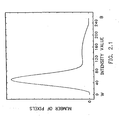
- FIG. 2.1 is a diagram of a histogram of an image having a background intensity range offset toward an extreme intensity value.
- FIG. 2.2 is a diagram of a histogram of an image having a background with an intermediate intensity range.
- FIG. 2.3 is a diagram of a histogram of an image as in Fig. 2.2 after background intensity value correction according to the present invention.
- FIG. 2.4 is a diagram of a histogram of a chrominance component of a color image showing more than one background peak representing different color regions in the image before correction for nonuniformities in the backgrounds.
- FIG. 2.5 is a diagram of a histogram of a chrominance component of a color image showing more than one background peak representing different color regions in the image after correction.
- FIG. 3 is a flow chart of an embodiment of the image processing method according to the present invention.
- FIG. 4 is a block diagram of apparatus embodying the image processor according to the present invention.
- FIG. 5 is a flow chart of an embodiment of the decoding method according to the present invention.
- FIG. 6 is a block diagram of apparatus embodying the decoder according to the present invention.
- In the drawing, like elements are designated with similar reference numbers, and identical elements in different specific embodiments are designated by identical reference numbers.
- A video conferencing system is generally made up of at least two stations each of which includes some means for acquiring one or more images; a means for processing the image for efficient storage and transmission and a means for controlling communications between the image processor and the other stations in the video conference by telephone lines or the like.
- A block diagram of one such station is shown in FIG. 1 in which an image is acquired by an
image acquisition device 12 such as by a vidicon camera or the like, processed by animage processor 14 such as a Motorola 68000 microprocessor controlled by a generalpurpose communications controller 16 such as an IBM Series/I. At the receiver another general purpose communications controller 16' controls another image processor 14' which processes the data. The output data may be fed to a suitable utilization device such as animage display 18. - The image processor (14, 14') shown in FIG. 1, provides the functions which make up the method and apparatus according the the present invention.
- At the heart of the present invention is a histogram analysis of the acquired image. Representative histograms are shown in FIGS. 2.1, 2.2, 2.3, 2.4 and 2.5 and will be described in further detail. The histogram of FIG. 2.1 shows the distribution of number of pixels along the vertical axis as compared to intensity value along the horizontal axis. Assuming a black/white image with a nominally white background and black data thereon, the histogram of FIG. 2.1 would be representative of a black/white graphics image having a large number of pixels with a near white gray scale value, indicating the background of the document, and a much smaller number of pixels at darker gray scale values indicating the graphics data on the document. Typically, 90% of a graphics document may be considered background whereas 10% or less contains information.
- This is shown by the large peak near the white end of the scale and the smaller value near the black end of the scale as shown in FIG. 2.1.
- By contrast, FIG. 2.2 shows a histogram of an image in which the background peak occurs at some gray scale value substantially darker than the white level of FIG. 2.1 but not in the blackest level which would indicate white data on a black background. The histogram of FIG. 2.2 is most representative of a color document in which the background has a definite color with an intermediate gray scale value.
- In such a case, there may be data having gray scale values of lower gray scale values than the background as well as data having higher gray scale values than the background. Thus, there will be information content on either side of the peak shown in FIG. 2.2.
- Among other aspects of the present invention, it is intended to reduce the background gray scale level to substantially a single value as is shown in FIG. 2.3 with information carrying gray scale pixels both above and below the background peak along the axis of gray scale values.
- The process of reducing the background peak to a single value may be referred to as "clipping" or"coring". Clipping is the process of reducing all values on one side of a peak to a single value, while coring is the process of selecting a predetermined range around a peak, reducing all values within the range to a single value while shifting values outside the range on both sides of the peak toward the peak to eliminate discontinuities in the image. Both terms will be used to refer to the process of determining a peak value for the background, determining edges of the background range and reducing the range of background values to a single value to eliminate noise in the background of a document. Clipping is a special case of coring where one side of the peak is an extreme value such as black or white. Clipping is used primarily on black/white images while coring is used on images having multiple colors.
- Table I below shows the clipping of values on one side of a peak to a single value (a8) where the background range has been defined as plus or minus 30 units from the peak.

- FIG. 2.4 and 2.5 show histograms of a chrominance component of a color image such as the R-Y or B-Y signal before (FIG. 2.4) and after (FIG. 2.5) coring correction for a multiple color background image. Note that the position of the peaks in the histogram along the horizontal axis represents different color intensity of the background colors.
- Referring now to FIG. 3, the encoding method according to the present invention will be described with reference to the flow chart. After an image to be processed is acquired by image acquisition means 12, (See FIG. 1)
image processor 14 first generates a histogram such as shown in FIGS. 2.1, 2.2 or 2.4. Next, the histogram is analyzed to find the minimum, maximum, peak and edges of the background range. - Next, a shading correction matrix is created for the luminance signal Y in a color image or for the gray scale intensity signal in a black/white image by averaging pixels in a block such as 16 lines by 32 pixels by taking the average of every other pixel on a given line and averaging the sums obtained for every other line in the block. For the first block of 16 lines in the image, pixel gray scale values are clipped to fall within the background image. Then, beginning again at the start of the image, blocks of 16 by 32 pixels are averaged. The shading correction value derived from the previous block is used for each pixel whose value falls outside the background range gray scale values to avoid distortion of shading correction due to image regions having primarily image data outside the background region.
- Due to discontinuities at the top and bottom and left and right edges of an image, the block averages from the top and bottom are replicated to provide approximate correction for the top and bottom edges of the image as are the block averages at the left and right edges of the image. A peak gray scale value is subtracted from the average value obtained above for each block to obtain a signed correction to be combined with each pixel gray scale value in the image to obtain a gray scale corrected image.
- Next, a lookup table is generated to core a final corrected image thus flattening the background to a single gray scale level at the peak value of the background range. The table also provides clipping at the extrema to keep the final video output within a predetermined range such as 0 to 255.
- The coring range can be assumed to be centered on the background peak value. It has been demonstrated that the corrected image is typically very sharply peaked with a background range of plus and minus 5 units out of 255 units. If the background range is broader in the corrected image, the image is most likely not a graphics image and coring should be done very conservatively. Therefore, no analysis of the shading corrected image is needed. Since the coring range is so narrow, the table is generated with unity slope except in the clipping regions at the extremes and the coring region in the background range and with no first order discontinuities.
- Table II below is used after shading correction. The background is expected to be sharply peaked.


- Next, the shading correction values generated above are combined with the pixel gray scale values to obtain the shading corrected image. Bilinear interpolation is employed on the correction matrix to obtain correction values for each pixel.
- Next, a smoothing filter is applied to those pixels in the image having a gray scale value outside the background range; that is, to pixels having image data content. The smoothing filter may employ the technique shown in U. S. Patent 4,504 864.
- The corrected image data is then encoded employing gray scale encoding techniques such as is shown in Anastassiou and Mitchell, U. S. Patent 4,369,463 and Mitchell and Pennebaker U. S. Patent 4,488,174.
- The process described above with reference to FIGS. 3 generally relates to the correction and encoding of an image.
- Additionally, at a receiver, the encoded image data is decoded by the method shown in FIG. 5. The image is then reconstructed and all pixels are remapped to match the dynamic range and image format of the receiving system. The output data is also slightly cored to reduce streaking in the received image.
- Referring now to FIG. 4, a block diagram of apparatus for performing the clipped shading correction and encoding according to the present invention is shown. Raw image data is input to a
histogram generator 40 which provides outputs to a background range andpeak detector 42.Peak detector 42 detects the limits of the background range and the gray scale value at peak of the background range. These values are provided to the shadingcorrection matrix generator 48. The output of shading correction matrix is fed tocorrection adder 52 where it is added to the image data to achieve a shading corrected image. The shading corrected image is then fed to a coring lookup table 44 which generates a single intensity value at the peak of the background range to limit the background to a single intensity value for each background range in an image. The nonbackground graphics data is then filtered by a smoothing filter such as is described in U. S. Patent 4,504 864 and the smoothed data is then encoded bydata compression encoder 54 and transmitted to a receiving station or stored for later use. - Referring now to FIG. 5, the decoding method at the receiver will be described.
- Parameters contained in the encoded data received are used to create a coring table. This coring table is employed to reduce noise created during the encoding quantization process.
- The data is next tested to determine whether the data is a graphics image or a gray scale image. If the data represents a graphics image, a dynamic range enhancement routine is then employed to stretch gray scale values to black and white extremes to correct for shifting in the coring or clipping process at the encoder. If the image is not a graphics image, the dynamic range enhancement routine is not employed.
- Next, the image data is decoded pel by pel employing a well known gray scale decoding algorithm such as is shown in US Patent 4,369,463 and US Patent 4,488,174.
- The decoded data is then translated by reference to the clipping table of Table IV or the coring table of Table V (depending on whether the image data was clipped or cored at the encoder) created from the received parameters to correct for the encoding quantization noise to achieve a reproduced image with a flat background. It should be noted that although a background range of 30 units may be selected at the encoder, the deviation from peak value received at the decoder will generally be within 5 units. Thus, Tables IV and V can handle the general case at the decoder.
- Referring now to FIG. 6, a block diagram of apparatus embodying the decoder according to the present invention will be described.
- The encoded input data is fed to clipping/
coring table generator 62 which creates the clipping and coring tables as shown in tables IV and V below.Table generator 62 has two sets of outputs. The first output is connected togray scale decoder 68 and a second output tographics image detector 64. Thegraphics image detector 64 has an output indicating a graphics image has been detected which is an input to range expansion table 66.Gray scale decoder 68 provides decoded image data to translation andstorage matrix 70. Translation andstorage matrix 70 also communicates directly withtable generator 62 and range expansion table 66.

- As the image data is decoded, and decoded data is sent to translation and
storage matrix 70, the translation andstorage matrix 70 accesses table 62 and range expansion table 66 for graphics images to obtain translated corrected values for each decoded pixel in an image. These translated and corrected pixel values are then stored or displayed on a display screen (not shown). - The dynamic range expansion table 66 is implemented by TABLE VI below

- Alternatively, to eliminate one table lookup operation, per image, tables IV and VI are combined into table VII (below) for clipped images and tables V and VI are combined into table VIII (below) for cored images.


- A detailed program embodiment of the method according to the present invention is described below. function gethist fbbase(p); pointer bOsv; b0sv=b0 vcuhist fbbase 12 468 3 12 500 function vcuhist fbbase(p) y(h) ymax(h) dy(h) xst(h) xstp(h); pointer bOsv blsv b2sv; half hist(base b2); b0sv=b0 blsv=bl b2sv=b2 yy=0 b2=addr histbuf fill b2 0 512 dd7=0 bl=fbbase comhi=hex 35 lncnt=expl -xstp xst lncnt=srl lncnt 1 begin ylo=expl yy yhi=+ yh expl srl yy 8 xlo=expl xst xhi=xh bl=+bl 14 dd9=expl lncnt dd7=+dd7 dd9 dd2=0 dd9=-dd9 1 label loop dd2=0 dd2=dlo dd2=dlo ADD.W dd2,dd2 ADDQ.W #1,0 (b2,D2.W) DBRA dd9,.loop bl=-bl 14 yy=+yy expl dy if yy_>expl ymax repeat endif endbegin cnt=expl dd7 b0=b0sv bl=blsv b2=b2sv endfn minmax function minmax; bl=addr histbuf b0=bl dd9=0 begin dd9=+ dd9 expl histdata bl=+ bl 2 if dd9 11t 32 repeat endif endbegin begin if histdata>0 b1=- bl 2 if bl lgt b0 repeat endif endif endbegin min= srl expl - bl expl b0 1 b0=+ b0 510 b1=b0 dd9=expl histdata begin if dd9 llt 32 bl=- bl 2 dd9=+ dd9 expl histdata repeat endif endbegin begin if histdata>0 bl=+ bl 2 if bl llt b0 repeat endif endif endbegin max= sr1 expl - bl expl -b0 510 1 if max lgt 255 max=255 endif if min lgt 255 min=0 endif if min > max min=max endif endfn median function median; dd8=expl srl cnt 1 b0=addr histbuf bl=+b0 510 dd9=expl histdata begin if dd9 llt dd8 bl=- bl 2 dd9=+ dd9 expl histdata repeat endif endbegin med=expl srl expl - bl expl b0 1 if med lgt 255 med=255 endif endfn peakedge function peakedge; bl=addr histbuf dd2=expl ++++histdata histdata2 histdata4 histdata6 histdata8 dd9=0 b0=+b1 500 begin if dd2 lgt dd9 dd9=dd2 b2=bl endif dd2=+dd2 expl histdatalO dd2=-dd2 expl histdata bl=+bl 2 if bl lle b0 repeat endif endbegin fndedge 3 function fndedge edgedef(w); bl=b2 dd2=dd9 dd7=dd9 dd7=srl expl dd7 edgedef b0=+addr histbuf 500 begin if bl 11e b0 dd2=+dd2 expl histdata10 dd2=-dd2 expl histdata bl=+bl 2 if dd2 lgt dd7 repeat endif endif endbegin dd8=-expl bl 2 dd2=dd9 bl=b2 b0=addr histbuf begin if bl lgt b0 bl=-bl 2 dd2=+dd2 expl histdata dd2=-dd2 expl histdata10 if dd2 lgt dd7 repeat endif endif endbegin dd7= srl -dd8 expl b0 1 dd8= srl expl -bl expl b0 1 dd2=dd7 dif=expl srl -dd2 dd8 1 dd2= expl srl +dd7 dd8 1 dd2=+dd2 2 ehi=expl +dd2 expl dif elo=expl -dd2 expl dif if ehi lgt 255 ehi=255 endif if elo lgt 255 elo=0 endif endfn if -max min < sll dif 2 fndedge 2 if -max min < sll dif 2 fndedge 1 endif endif peak=+srl expl -b2 expl addr histbuf 1 2 if min > peak peak=min endif if max < peak peak=max endif dd9=0 bl=+bl 4 b0=+bl expl sll dif 2 begin dd9=+dd9 expl histdata bl=+bl 2 if b1 lle b0 repeat endif endbegin peakpc=percent expl cnt expl dd9 function percent num(w) denom(w); dd9=expl denom dd8=dd9 dd8=sll dd8 2 dd7=dd8 dd7=sll dd7 3 dd9=dd7 dd9=+dd9 dd8 dd7=sll dd7 1 dd9=+dd9 dd7 dd8=expl num begin if dd8 lgt hex ffff dd8=srl dd8 1 dd9=srl dd9 1 repeat endif endbegin if dd8=0 DIVU dd8,dd9 return ashalf expl dd9 else return ashalf 100 endif endfn endfn b0=b0sv endfn function shdget fbbase(p); pointer bOsv blsv b2sv; b0sv=b0 blsv=bl b2sv=b2 bl=fbbase firstblk function firstblk; static half tembuf (32); comhi=hex 35 comlo=0 fill tembuf 0 64 dd7=expl elo dd9=expa -ehi elo b0=+addr tembuf 32 yy=0 yblk=14 begin b2=-b0 32 ylo=expl yy yhi=+yh expl srl yy 8 xlo=0 xhi=xh bl=+bl 14 dd1=0 begin replace twopix0; dd2=0 dd2=dlo dd2=dlo dd2=-dd2 dd7 if dd2 lgt dd9 if dd2>0 dd2=dd9 else dd2=0 endif endif endrepl replace twopixl; ddl=dlo ddl=dlo ddl=-ddl dd7 if ddl 1gt dd9 if ddl>0 dd2=+dd2 dd9 endif ddl=0 else dd2=+dd2 ddl endif endrepl twopix0 twopixl twopixl twopixl twopixl twopixl twopixl twopixl twopixl twopixl twopixl twopixl twopixl twopixl twopixl twopixl dd2=srl dd2 4 tshd0=+tshd0 expl dd2 b2=+b2 2 if yy = yblk tshdml=srl tshdml 3 endif if b2 llt b0 repeat endif endbegin bl=-bl 14 if yy < yblk yy=+yy 2 repeat endif endbegin endfn yy=0 begin if yy<478 bl=fbbase midblk function midblk; dd7=expl elo dd9=expa -ehi elo b0=+Gfirstblk 64 yblk=+yy 14 begin b2=-b0 32 ylo=expl yy yhi=+yh expl srl yy 8 xlo=0 xhi=xh bl=+bl 14 ddl=0 dd8=0 begin dd8=oldtshd0 replace twopix0; dd2=0 dd2=dlo dd2=dlo dd2=-dd2 dd7 if dd2 lgt dd9 dd2=dd8 endif endrepl replace twopixl; ddl=dlo ddl=dlo ddl=-ddl dd7 if ddl lgt dd9 ddl=0 dd2=+dd2 dd8 else dd2=+dd2 ddl endif endrepl twopix0 twopixl twopixl twopixl twopixl twopixl twopixl twopixl twopixl twopixl twopixl twopixl twopixl twopixl twopixl twopixl dd2=srl dd2 4 tshd0=+tshd0 expl dd2 b2=+b2 2 if yy = yblk tshdml=srl tshdml 3 endif if b2 llt b0 repeat endif endbegin bl=-bl 14 if yy < yblk yy=+yy 2 repeat endif endbegin yy=+yy 2 b2=-b2 32 bl= expl sll srl yy 4 4 bl=+bl expl addr shdbuf dd8=dd7 dd8=-dd8 expl peak begin dd2=expl tshd0 tshd0=0 oldtshd0=expl dd2 b2=+b2 2 dd2=+dd2 dd8 datalb=expl dd2 bl=+bl 1 if b2 llt b0 repeat endif endbegin endfn repeat endif endbegin b2=addr shdbuf bl=+b2 16 begin shdc0=shdcl6 shdc496=shdc480 b2=+b2 1 if b2 11t bl repeat endif endbegin b0=b0sv bl=blsv b2=b2sv endfn function coretbl; pointer bOsv blsv; static half diff; init diff 5; b0sv=b0 blsv=bl (generate coring table from -128 to + 256 128) fill cortbl 0 expl -128 diff b0=+addr cortbl expl -128 diff dd8=expl peak dd9=0 begin data0b=expl dd9 b0=+b0 1 dd9=+dd9 1 if dd9 llt dd8 repeat endif endbegin fill b0 expl dd8 expl +diff diff dd8=255 b0=+b0 expl +diff diff begin data0b=expl dd9 b0=+b0 1 dd9=+dd9 1 if dd9 llt dd8 repeat endif endbegin fill b0 255 expl -+addr cortbl 512 expl b0 b0=b0sv bl=blsv endfn function shdcor fbbase(p) yy(h) databuf(p); pointer bOsv blsv b2sv; b0sv=b0 blsv=bl b2sv=b2 yy=and hex 1ff yy if _ (yy_<ymax) (yy<ymin) vinterp and hex lf8 yy endif bl=fbbase comhi=hex 35 comlo=0 xlo=0 xhi=xh ylo=expl and hex ff yy yhi=expl and 1 srl yy 8 b2=expl sll and +yy 8 hex f 1 b2=+b2 sll expl b2 3 b2=+addr tbuf expl b2 b0=databuf b0lim=+databuf 1024 bl=+bl 14 aOsv=AO alsv=Al MOVE.B shdc0+,dd2 EXT.W dd2 MOVE.W dd2,A0 dd0=expl +addr filtbl 256 MOVE.L dd0,Al dd0=expl +addr cortbl 128 MOVE dd0,A3; MOVEQ.L _0,D7 MOVEQ.L 0,dd0 MOVE.B dlo,dd0 MOVEQ.L _0,dd9 begin MOVE.W A0,dd8 MOVE.B shdc0+,dd2 EXT.W dd2 MOVE.W dd2,A0 call blockl6 MOVE.W A0,dd8 MOVE.B shdc0,dd2 EXT.W dd2 ADD.W dd8,dd2 ASR.W _$l,dd2 MOVE.W dd2,A0 call blockl6 if b0 llt bOlim repeat else b0=-b0 2 if dataout0=_expl peak ASR.W _2,D7 SUB.W D7,dd9 MOVE.B 0(A3,dd9.W),dataout0 endif endif endbegin A0=a0sv Al=alsv b0=b0sv bl=blsv b2=b2sv subr block16 replace teste cor(t) MOVEQ _0,dd9 MOVE.B dlo,dd9 MOVE.W dd9,D6 SUB.W ddO,D6 MOVE.B 0(A1,D6.W),D6 EXT.W D6 SUB.W D6,D7 ASR.W _2,D7 SUB.W D7,dd0 SUB.W cor,dd0 MOVE.B 0(A3,dd0.W),dataout0 ADDQ.L _2,b0 endrepl replace testo cor(t) MOVEQ _0,dd0 MOVE.B dlo,dd0 MOVE.W ddO,D7 SUB.W dd9,D7 MOVE.B 0(A1,D7.W),D7 EXT.W D7 SUB.W D7,D6 ASR.W 2,D6 SUB.W D6,dd9 SUB.W cor,dd9 MOVE.B 0(A3,dd9.W),dataout0 ADDQ.L 2,b0 endrepl teste dd8 MOVE.W dd8,dd7 ADD.W A0,dd7 ASR.W _1,dd7 MOVE.W A0,dd2 SUB.W dd8,dd2 ADDQ.W _4,dd2 CMP.W _8,dd2 BLS .tminn MOVE.W dd7,dd2 ADD.W dd8,dd2 ASR.W _1,dd2 MOVE.W dd2,dd1 ADD.W dd8,ddl ASR.W _1,ddl ADD.W ddl,dd8 ASR.W _1,dd8 testo dd8 teste ddl ADD.W dd2,ddl ASR.W _1,dd1 testo ddl teste dd2 MOVE.W dd2,dd8 ADD.W dd7,dd8 ASR.W _1,dd8 ADD.W dd8,dd2 ASR.W _1,dd2 testo dd2 teste dd8 ADD.W dd7,dd8 ASR.W _1,dd8 testo dd8 teste dd7 MOVE.W dd7,dd8 ADD.W A0,dd8 ASR.W _1,dd8 MOVE.W dd7,dd2 ADD.W dd8,dd2 ASR.W _1,dd2 ADD.W dd2,dd7 ASR.W _1,dd7 testo dd7 teste dd2 ADD.W dd8,dd2 ASR.W 1,dd2 testo dd2 teste dd8 MOVE.W dd8,dd2 ADD.W AO,dd2 ASR.W 1,dd2 ADD.W dd2,dd8 ASR.W 1,dd8 testo dd8 teste dd2 ADD.W AO,dd2 ASR.W 1,dd2 testo dd2 retrn label tminn testo dd8 teste dd8 testo dd8 ADD.W dd7,dd8 ASR.W 1,dd8 teste dd8 testo dd8 teste dd8 testo dd8 teste dd7 testo dd7 teste dd7 testo dd7 ADD.W AO,dd7 ASR.W 1,dd7 teste dd7 testo dd7 teste dd7 testo dd7 endsubr endfn endfn
Claims (16)
means (68) for decoding said image data using an appropriate gray scale decoding algorithm; and means for correcting said image data for dynamic range compression by reference to said dynamic range expansion table.
Applications Claiming Priority (2)
| Application Number | Priority Date | Filing Date | Title |
|---|---|---|---|
| US69200785A | 1985-01-15 | 1985-01-15 | |
| US692007 | 1985-01-15 |
Publications (2)
| Publication Number | Publication Date |
|---|---|
| EP0188193A2 true EP0188193A2 (en) | 1986-07-23 |
| EP0188193A3 EP0188193A3 (en) | 1989-04-19 |
Family
ID=24778895
Family Applications (1)
| Application Number | Title | Priority Date | Filing Date |
|---|---|---|---|
| EP86100035A Withdrawn EP0188193A3 (en) | 1985-01-15 | 1986-01-02 | Method and apparatus for processing image data |
Country Status (2)
| Country | Link |
|---|---|
| EP (1) | EP0188193A3 (en) |
| JP (1) | JPS61168078A (en) |
Cited By (12)
| Publication number | Priority date | Publication date | Assignee | Title |
|---|---|---|---|---|
| WO1989012278A1 (en) * | 1988-06-08 | 1989-12-14 | Quantel Limited | Method and apparatus for image enhancement |
| EP0524695A1 (en) * | 1991-07-26 | 1993-01-27 | Océ-Nederland B.V. | Method of determining a reference value for the intensity associated with a colour indication variable and obtained by scanning an original with a colour scanning unit, and a system for performing such method |
| EP0534430A2 (en) * | 1991-09-27 | 1993-03-31 | Dainippon Screen Mfg. Co., Ltd. | Method of and apparatus for converting image signal representing image having gradation |
| EP0635802A1 (en) * | 1993-06-09 | 1995-01-25 | Kodak Limited | A method of processing a digital detail signal |
| NL9401600A (en) * | 1994-02-18 | 1995-10-02 | Mitsubishi Electric Corp | System and method for processing an image. |
| EP0963106A2 (en) * | 1998-06-01 | 1999-12-08 | Xerox Corporation | Background noise removal for a low-cost digital color copier |
| US6038340A (en) * | 1996-11-08 | 2000-03-14 | Seiko Epson Corporation | System and method for detecting the black and white points of a color image |
| WO2002037832A2 (en) * | 2000-11-01 | 2002-05-10 | Hewlett-Packard Company | System and method for enhancing scanned document images for color printing |
| EP1283498A2 (en) * | 2001-08-06 | 2003-02-12 | Nissan Motor Company, Limited | White line detection apparatus and white line detection method |
| EP1755329A1 (en) * | 2005-08-16 | 2007-02-21 | Océ-Technologies B.V. | Conversion method, apparatus and computer program for converting a digital image obtained by a scanner |
| CN105005980A (en) * | 2015-07-21 | 2015-10-28 | 深圳Tcl数字技术有限公司 | Image processing method and device |
| CN105389825A (en) * | 2015-12-22 | 2016-03-09 | 深圳Tcl数字技术有限公司 | Image processing method and system |
Citations (5)
| Publication number | Priority date | Publication date | Assignee | Title |
|---|---|---|---|---|
| US3743772A (en) * | 1969-11-12 | 1973-07-03 | Meldreth Electronics Ltd | Image analysing |
| US4271436A (en) * | 1978-05-02 | 1981-06-02 | Ricoh Co., Ltd. | Digital copying machine |
| US4354243A (en) * | 1980-04-11 | 1982-10-12 | Ampex Corporation | Two dimensional interpolation circuit for spatial and shading error corrector systems |
| EP0082318A1 (en) * | 1981-12-21 | 1983-06-29 | Hughes Aircraft Company | Real time dynamic range compression method and apparatus for image enhancement |
| GB2112602A (en) * | 1981-12-24 | 1983-07-20 | Int Computers Ltd | Image digitising system |
-
1985
- 1985-09-13 JP JP60201910A patent/JPS61168078A/en active Pending
-
1986
- 1986-01-02 EP EP86100035A patent/EP0188193A3/en not_active Withdrawn
Patent Citations (5)
| Publication number | Priority date | Publication date | Assignee | Title |
|---|---|---|---|---|
| US3743772A (en) * | 1969-11-12 | 1973-07-03 | Meldreth Electronics Ltd | Image analysing |
| US4271436A (en) * | 1978-05-02 | 1981-06-02 | Ricoh Co., Ltd. | Digital copying machine |
| US4354243A (en) * | 1980-04-11 | 1982-10-12 | Ampex Corporation | Two dimensional interpolation circuit for spatial and shading error corrector systems |
| EP0082318A1 (en) * | 1981-12-21 | 1983-06-29 | Hughes Aircraft Company | Real time dynamic range compression method and apparatus for image enhancement |
| GB2112602A (en) * | 1981-12-24 | 1983-07-20 | Int Computers Ltd | Image digitising system |
Cited By (25)
| Publication number | Priority date | Publication date | Assignee | Title |
|---|---|---|---|---|
| WO1989012278A1 (en) * | 1988-06-08 | 1989-12-14 | Quantel Limited | Method and apparatus for image enhancement |
| EP0524695A1 (en) * | 1991-07-26 | 1993-01-27 | Océ-Nederland B.V. | Method of determining a reference value for the intensity associated with a colour indication variable and obtained by scanning an original with a colour scanning unit, and a system for performing such method |
| US5400153A (en) * | 1991-07-26 | 1995-03-21 | Oce-Nederland, B.V. | System and method of determining a reference value for the intensity associated with a color indication variable obtained by scanning an original with a color scanning unit |
| EP0534430A2 (en) * | 1991-09-27 | 1993-03-31 | Dainippon Screen Mfg. Co., Ltd. | Method of and apparatus for converting image signal representing image having gradation |
| EP0534430A3 (en) * | 1991-09-27 | 1993-07-07 | Dainippon Screen Mfg. Co., Ltd. | Method of and apparatus for converting image signal representing image having gradation |
| US5680477A (en) * | 1991-09-27 | 1997-10-21 | Dainippon Screen Mfg. Co., Ltd. | Method of and apparatus for converting image signal representing image having gradation |
| EP0635802A1 (en) * | 1993-06-09 | 1995-01-25 | Kodak Limited | A method of processing a digital detail signal |
| NL9401600A (en) * | 1994-02-18 | 1995-10-02 | Mitsubishi Electric Corp | System and method for processing an image. |
| US6038340A (en) * | 1996-11-08 | 2000-03-14 | Seiko Epson Corporation | System and method for detecting the black and white points of a color image |
| EP0963106A3 (en) * | 1998-06-01 | 2002-05-22 | Xerox Corporation | Background noise removal for a low-cost digital color copier |
| EP0963106A2 (en) * | 1998-06-01 | 1999-12-08 | Xerox Corporation | Background noise removal for a low-cost digital color copier |
| WO2002037832A3 (en) * | 2000-11-01 | 2002-08-29 | Hewlett Packard Co | System and method for enhancing scanned document images for color printing |
| WO2002037832A2 (en) * | 2000-11-01 | 2002-05-10 | Hewlett-Packard Company | System and method for enhancing scanned document images for color printing |
| US6621595B1 (en) | 2000-11-01 | 2003-09-16 | Hewlett-Packard Development Company, L.P. | System and method for enhancing scanned document images for color printing |
| EP1283498A2 (en) * | 2001-08-06 | 2003-02-12 | Nissan Motor Company, Limited | White line detection apparatus and white line detection method |
| EP1283498A3 (en) * | 2001-08-06 | 2003-07-09 | Nissan Motor Company, Limited | White line detection apparatus and white line detection method |
| US6925206B2 (en) | 2001-08-06 | 2005-08-02 | Nissan Motor Co., Ltd. | White line detection apparatus and white line detection method |
| US7646911B2 (en) | 2005-08-16 | 2010-01-12 | Oce-Technologies B.V. | Conversion method, apparatus and computer program for converting a digital image obtained by a scanner |
| EP1755329A1 (en) * | 2005-08-16 | 2007-02-21 | Océ-Technologies B.V. | Conversion method, apparatus and computer program for converting a digital image obtained by a scanner |
| CN105005980A (en) * | 2015-07-21 | 2015-10-28 | 深圳Tcl数字技术有限公司 | Image processing method and device |
| WO2017012418A1 (en) * | 2015-07-21 | 2017-01-26 | 深圳Tcl数字技术有限公司 | Image processing method and apparatus |
| CN105005980B (en) * | 2015-07-21 | 2019-02-01 | 深圳Tcl数字技术有限公司 | Image processing method and device |
| CN105389825A (en) * | 2015-12-22 | 2016-03-09 | 深圳Tcl数字技术有限公司 | Image processing method and system |
| WO2017107395A1 (en) * | 2015-12-22 | 2017-06-29 | 深圳Tcl数字技术有限公司 | Image processing method and system |
| CN105389825B (en) * | 2015-12-22 | 2018-11-23 | 深圳Tcl数字技术有限公司 | Image processing method and system |
Also Published As
| Publication number | Publication date |
|---|---|
| JPS61168078A (en) | 1986-07-29 |
| EP0188193A3 (en) | 1989-04-19 |
Similar Documents
| Publication | Publication Date | Title |
|---|---|---|
| US5111285A (en) | Video printer device | |
| JP3759761B2 (en) | Method and apparatus for changing sharpness | |
| US6614471B1 (en) | Luminance correction for color scanning using a measured and derived luminance value | |
| US7570390B2 (en) | Image processing device and method | |
| US4486785A (en) | Enhancement of video images by selective introduction of gray-scale pels | |
| US6462835B1 (en) | Imaging system and method | |
| US5181105A (en) | Color image correction based on characteristics of a highlights or other predetermined image portion | |
| EP1326425B1 (en) | Apparatus and method for adjusting saturation of color image | |
| US8199227B2 (en) | Image-signal processing apparatus for performing space-variant image-signal processing | |
| EP0747855A2 (en) | Method and apparatus for enhancing a digital image | |
| EP0188193A2 (en) | Method and apparatus for processing image data | |
| US5321500A (en) | Non-real-time film scanning system | |
| EP0442369B1 (en) | Gradation correcting apparatus | |
| US5363210A (en) | Apparatus outputting quantized image data, selecting from filters with different error spreading effects | |
| WO1990007836A1 (en) | Optical image to video transfer system having enhanced resolution and contrast for dark areas of the image | |
| US6442294B1 (en) | Digital image processing apparatus with interpolation and adder circuits | |
| US4639781A (en) | Dynamic gain adjuster for an image scanner | |
| US6031581A (en) | System for removing color bleed in a television image adapted for digital printing | |
| JPH0659106B2 (en) | Video image processor | |
| JPH07193724A (en) | Image processing device and method for creating data representing color picture | |
| US5798842A (en) | Image processing apparatus for subjecting a color image to desired gradation processing | |
| US7421143B2 (en) | Systems and methods for optimal dynamic range adjustment of scanned images | |
| JPS62242473A (en) | Pseudo halftone image processor | |
| JP3368966B2 (en) | Shading correction device and shading correction method | |
| JPS63214073A (en) | Image processing method |
Legal Events
| Date | Code | Title | Description |
|---|---|---|---|
| PUAI | Public reference made under article 153(3) epc to a published international application that has entered the european phase |
Free format text: ORIGINAL CODE: 0009012 |
|
| AK | Designated contracting states |
Kind code of ref document: A2 Designated state(s): DE FR GB |
|
| 17P | Request for examination filed |
Effective date: 19861125 |
|
| PUAL | Search report despatched |
Free format text: ORIGINAL CODE: 0009013 |
|
| AK | Designated contracting states |
Kind code of ref document: A3 Designated state(s): DE FR GB |
|
| 17Q | First examination report despatched |
Effective date: 19910130 |
|
| STAA | Information on the status of an ep patent application or granted ep patent |
Free format text: STATUS: THE APPLICATION HAS BEEN WITHDRAWN |
|
| 18W | Application withdrawn |
Withdrawal date: 19910722 |
|
| R18W | Application withdrawn (corrected) |
Effective date: 19910722 |
|
| RIN1 | Information on inventor provided before grant (corrected) |
Inventor name: MITCHELL, JOAN LA VERNE Inventor name: PENNEBAKER, WILLIAM BOONE |