EP0187677A2 - Linking system for programmable controller - Google Patents
Linking system for programmable controller Download PDFInfo
- Publication number
- EP0187677A2 EP0187677A2 EP86100287A EP86100287A EP0187677A2 EP 0187677 A2 EP0187677 A2 EP 0187677A2 EP 86100287 A EP86100287 A EP 86100287A EP 86100287 A EP86100287 A EP 86100287A EP 0187677 A2 EP0187677 A2 EP 0187677A2
- Authority
- EP
- European Patent Office
- Prior art keywords
- programmable controllers
- programmable
- link
- master controller
- data
- Prior art date
- Legal status (The legal status is an assumption and is not a legal conclusion. Google has not performed a legal analysis and makes no representation as to the accuracy of the status listed.)
- Granted
Links
Images
Classifications
-
- G—PHYSICS
- G05—CONTROLLING; REGULATING
- G05B—CONTROL OR REGULATING SYSTEMS IN GENERAL; FUNCTIONAL ELEMENTS OF SUCH SYSTEMS; MONITORING OR TESTING ARRANGEMENTS FOR SUCH SYSTEMS OR ELEMENTS
- G05B19/00—Programme-control systems
- G05B19/02—Programme-control systems electric
- G05B19/04—Programme control other than numerical control, i.e. in sequence controllers or logic controllers
- G05B19/05—Programmable logic controllers, e.g. simulating logic interconnections of signals according to ladder diagrams or function charts
- G05B19/052—Linking several PLC's
Definitions
- This invention relates to a data linking system for a plurality of programmable controllers.
- a programmable controller or sequence controller
- a machine control in accordance with the development of computer utilizing techniques.
- a programmable controller controls the whole system in a conventional technique of this art of field, but it has become impossible to control the whole system with one programmable controller because of requirements of high performance and high speed operation based on the enlargement and the intricacy of the system.
- a plurality of programmable controllers have been recently installed for a large system provided with an intricated structure so as to carry out separately the group control thereof.
- the separate type control system since it is necessary to establish the interlock betwwen the separatede programmable controller groups, the data linking menas therebetween has been required.
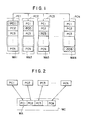
- FlGs.1 and 2 represent examples of the data linking system in the conventional technique in which FIG.1 represents a manner for a parallel link established by mutually connecting a plurality of programmable controllers PC1, PC2, PC3, ... PCN.
- memory areas MA1 to MAN provided for respective input/output areas, or inner relays or the like of the programmable controllers are split into N numbers of memory area groups which is to be allocated to the respective programmable controllers thereby to establish the fixed link therebetween in which the memory areas MA1 to MAN can always well correspond to the programmable controllers, respectively.
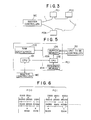
- FIG.2 represents another linking manner in which a plurality of programmable controllers PC1 to PCN are operatively connected to one master controller MC which is provided with a memory area MA including all link areas of the respective program memories and the memory area MA is allocated to the link areas of the programmable controllers, respectively.
- this arrangement it is possible to establish the linking of all the programmable controllers PC1 to PCN through the master controller MC, but the direct linking between the respective programmable controllers PC1 to PCN is prohibited.
- the linking is performed through the memory area MA of the master controller MC, so that the numbers of the linking means are naturally limited.
- An object of this invention is to eliminates problems and disadvantages encountered in the prior art technique and to provide an improved linking system for programmable controllers capable of linking optional memory areas of the programmable controllers regardless of the used numbers thereof and saving the data transferring time by linking only the memory areas actually used in accordance with a sequence progam.
- this and other objects can be accomplished by providing a linking system for a plurality of programmable controllers provided with inner relays for the linking respectively characterized in that the respective programmable controllers are connected to one programmable controllers controlling the aforementioned programmable controllers as a master controller, sequences of the programmable controllers are programmed in use of addresses representing optional input/output memory areas, link tables are prepared by automatically allotting input/output memory areas of the programmable controllers.
- the prepared link tables is registered into the master controller, the link tables are collected from the respective programmable controllers into the master controller at the link starting time to prepare an edit link table by collecting common portions of the collected link tables, input side and output side address tables are provided for the master controller and the respective programmable controllers, respectively, so that the linking is performed only by transfer of data and the data is periodically accessed and linked between the master controller and the respective programmable controllers in accordance with the input side and output side aaddress tables by the operation of the programmable controllers.
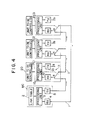
- a plurality, i.e. N numbers, of programmable controllers PC1 to PCN are operatively connected to one master controller MC by means of light loop which is formed with optical fibers 1.
- the programmable controllers PC1 to PCN control predetermined portions or units in the whole systems and the flow of the control in the whole system is preliminarily determined so that the data link between the respective programmable controllers PC1 to PCN can be made together with the designing of the whole system.
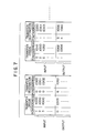
- FIG.4 shows an example in which three programmable controllers PC1 to PC3 are connected to the master controller MC in a loop form by means of the optical fibers 1.
- the master controller MC is provided with an editorial link table 2, described in detail hereinafter, and a processing unit 3 carrying out the necessary data processing in use of a micro computer and so on.
- An information transferred from the optical fibers 1 is converted by the receiver 4 into an electric signal wihch is then inputted into the processing unit 3.
- the information from the processing unit 3 is converted by a transmitter 5 into a light signal which is then transferred to the optical fibers 1. Since the programmable controllers PC1 to PC3 have the same constructions, the construction of the programmable controllers PC1 will only be explained hereunder for the convenience sake.
- the programmable controller PC1 is provided with a processing unit 3 having the construction shown in delail in FIG.S.
- the information transferred through the optical fibers 1 is converted by a receiver 12 into an electric signal which is then inputted into a processing unit 10 as shown in FIG.4 and the information from the processing unit 10 is converted by a transmitter 1 3 into a light signal to be outputted therefrom.
- a switching unit 11 provided with contacts aand b is located at the junction points of the optical fibers 1 of the programmable controller PC1 and the optical fibers 1 are usually connected to the contact a as shown in FIG. 4 so that the information from the optical fibers 1 is transferred to the receiver 12 and the succeeding programmable controllers PC2 and PC3 and is then returned to the receiver 4 of the master controller MC.
- the switching unit 11 is thereafter switched by the processing unit 10 and when the connection to the contact a is established to the contact b, the information to be inputted into the programmable controller PC1 is interrupted and the information outputted from the transmitter 13 is transferred to the optical fibers 1.
- the programmable controller PC1 is connected to a unit 20 to be controlled so as to output signals to an electromagnetic valve, a relay contact, a display lamp and the like of the unit 20 and to receive signals from a push button, a limit switch, a relay and the like in the unit 20.
- the processing unit 10 such as in the programmable controller PC1 is described hereunder with reference to FIG.5.
- the processing unit 10 is provided with a CPU (central processing unit) 101 such as a micro processor which controls the data transfer between the processing unit 10 and the master controller MC and with a CPU 102 which controls the data transfer between the processing unit 10 and the unit 20 to be controlled.
- the CPUs 101 and 102 are operatively connected to a common RAM (random access memory) 103 through a bus line 106.
- a sequence memory 104 storing a program with respect to the unit 20 is operatively connected to the CPU 102 so as to transmit and receive data and instructions through a buffer memory 105 between the CPU 102 and the unit 20 to be controlled.
- the RAM 1 03 is provided with a storage area (i.e. input area) for storing information transferred from another programmable controller linked to the RAM 1 03 and with a storage area (i.e. output area) for storing information of the subject programmable controller PC1 so as to transfer that information to the other programmable controller through the master controller MC.
- the transfer between the buffer memory 105 and the RAM 103 is controlled by the CPU 102 and the transfer between the subject programmable controller PC 1 and the other programmable controller is controlled by the CPU 102.
- FIG.6 shows a sequence program for the data link in use of the memory area such as optional input/output areas or inner relays of an optional programmable controller PC according to this invention.
- a necessary sequence for the operation of each programmable controller PC is first programmed with respect to the programmable controller PC in use of the optional input/output areas of the optional programmable controller PC.
- the respective programmable controllers PC as a portion from which the data is transferred (called transfer origin hereinafter) automatically allocated the input/output areas of the programmable controllers PC other than the subject one to the inner relays for the data link as shown in FIG.6.
- FIG.6 shows one example of the sequence program representing the numbers of the programmable controllers, the contents to be processed, and the processing addresses of the respective programmable controllers to be linked with respect to the programmable controllers PCO and PC1 and the inner relays for the data link are allocated to the respective sequences.
- the symbols "X” represents the input, "Y” the output.
- “R” the inner relay and “E” represents the inner relay for the link, and for example, with the programmable controller PCO, a symbol “1X000” represents the address “000” of the input of the programmable controller PC1 and is allocated in the address "000” of the inner relay for the link.
- a symbol “Y050” represents the address “050” of the output of the programmable controller PCO itself and is not allocated into the inner relay for the link.
- a symbol “3R000” represents the address "000” of the inner relay of the programmable controller PC3 and is allocated into the address "002" of the inner relay for the linking.
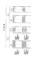
- FIG.7 shows link tables of the respective programmable controllers. These link tables are prepared before the starting of the linking operation as a preparation stage for editting the final link table in the master controller to clarify the transfer origin and the portion to which the data is transferred (called transfer destination hereinafter) with respect to the input and output sides, respectively.
- the link tables prepared for the respective programmable controllers are registered into the master controller after the preparation of the link tables.
- the number, the content and the addresses of the programmable controller as the transfer origin are collected in a table in accordance with the order of the addresses of the inner relay for the link with respect to the programmable controllers as the transfer destination.
- the addresses of the programmable controller into which the data is transferred in accordance with the order of the addresses of the inner relay for the link with respect to the programmable controller as the data transfer origin.
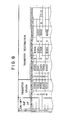
- FIG.8 shows a part of an editorial link table in the master controller, which operates to collect link tables prepared in the respective programmable controllers which have already been accommodated in the master controller at the data link starting time and to prepare an editorial link table by combining addresses of the programmable controllers to which the data is transferred and which are provided with addresses of the programmable controllers as the transfer origins commonly in accordance with the order of the addresses.
- the data link condition between the respec- five programmable controllers can be immediately recognized by monitoring the master controller in utilization of the thus prepared editorial link table.
- the editorial link table of the master controller is provided with pointers for designating the address of an area into which is stored data to be accessed and a pointer table consisting of ON-OFF information of the pointers.
- each of the respective programmable controllers is provided therein with input side and output side address tables in accordance with the input side and output side pointer tables of the master controller as shown in FlG.9.
- the input side pointers are pointers "0", “1", "2", and "4" and the output side pointer is a pointer 3 as shown FIG.S. This means that only memory areas of the programmable controllers which are actually utilized by using the pointers are linked.
- the master controller operates to write the information from the programmable controllers in the ON-OFF area of the editorial link table shown in FIG.8 in accordance with the order of the pointers of the input side pointer table, to read out the data from the editorial link table in FIG.8 in accordance with the order of the pointers of the output side pointer table, and then to transfer the read-out data into the area of the programmable controller the address of which is designated by the pointer.
- each of the respective programmable controllers operates to read out the data in accordance with the order of the input side address table of FIG.9, to transfer the read-out data into the master controller, and then to write the data transferred from the master controller into the input/output areas or inner relay with the address numbers of the output side address table.
- the number of the programmable controller is feed before the data transfer to respond only to the designated programmable controller.
- a programmable sequence can be programmed by utilizing input/output areas of optional ones of the respective programmable controllers thereby to link only the actually required areas, thus saving the data transfer time. Accordingly, the programmable controllers can be linked with no limit of the linking numbers thereof and optional areas of optional programmable controllers can be linked with the possibly shortest transfer time. In addition, a sequence program requiring the link between the programmable controllers can easily be prepared without paying specific attention to the memory areas of the programmable controllers.
Abstract
Description
- This invention relates to a data linking system for a plurality of programmable controllers.
- Recently, a programmable controller, or sequence controller, has been widely utilized for working, assembling, deliverying and the like operations of a machine control in accordance with the development of computer utilizing techniques. With these operative controls, only one programmable controller controls the whole system in a conventional technique of this art of field, but it has become impossible to control the whole system with one programmable controller because of requirements of high performance and high speed operation based on the enlargement and the intricacy of the system. On the basis of these technical requirements, a plurality of programmable controllers have been recently installed for a large system provided with an intricated structure so as to carry out separately the group control thereof. With the separate type control system, since it is necessary to establish the interlock betwwen the separatede programmable controller groups, the data linking menas therebetween has been required.
- FlGs.1 and 2 represent examples of the data linking system in the conventional technique in which FIG.1 represents a manner for a parallel link established by mutually connecting a plurality of programmable controllers PC1, PC2, PC3, ... PCN. In order to establish the data link between optional programmable controllers PC1 to PCN with this manner, memory areas MA1 to MAN provided for respective input/output areas, or inner relays or the like of the programmable controllers are split into N numbers of memory area groups which is to be allocated to the respective programmable controllers thereby to establish the fixed link therebetween in which the memory areas MA1 to MAN can always well correspond to the programmable controllers, respectively. However, in this linking manner, since memory areas each having the same capacity are allocated to the respectively corresponding programmable controllers regardless of the frequencies of the linkings, it will be said that this manner is not economical in the hardware technique, and there may cause a case where memory areas which are not substantially utilized are prepared for the requirement of few frequencies of the linking, thus being not economical. In addition, in a case where a large number of the programmable controllers constituting a system are to be disposed, the whole memory capacity therefor extremely increase as well as the increasing of the memory areas of blanks actually substantially not utilized. This will cause time loss in the data transferring time. In order to eliminates this problem, on the contrary, when the memory areas are made small, the link between the respective programmable controllers are freely established. Moreover, since the fixed area type link manner is adapted, it is necassary to arrange the sequence programs so as to input or output signals into or from the predetermined memory areas. This may cause loss of the programming operation.
- FIG.2 represents another linking manner in which a plurality of programmable controllers PC1 to PCN are operatively connected to one master controller MC which is provided with a memory area MA including all link areas of the respective program memories and the memory area MA is allocated to the link areas of the programmable controllers, respectively. According to this arrangement, it is possible to establish the linking of all the programmable controllers PC1 to PCN through the master controller MC, but the direct linking between the respective programmable controllers PC1 to PCN is prohibited. In addition, the linking is performed through the memory area MA of the master controller MC, so that the numbers of the linking means are naturally limited.
- An object of this invention is to eliminates problems and disadvantages encountered in the prior art technique and to provide an improved linking system for programmable controllers capable of linking optional memory areas of the programmable controllers regardless of the used numbers thereof and saving the data transferring time by linking only the memory areas actually used in accordance with a sequence progam.
- According to this invention, this and other objects can be accomplished by providing a linking system for a plurality of programmable controllers provided with inner relays for the linking respectively characterized in that the respective programmable controllers are connected to one programmable controllers controlling the aforementioned programmable controllers as a master controller, sequences of the programmable controllers are programmed in use of addresses representing optional input/output memory areas, link tables are prepared by automatically allotting input/output memory areas of the programmable controllers. to the inner relays, with respect to addresses of the respec- tve programmable controllers except for address of the subject programmable controller, the prepared link tables is registered into the master controller, the link tables are collected from the respective programmable controllers into the master controller at the link starting time to prepare an edit link table by collecting common portions of the collected link tables, input side and output side address tables are provided for the master controller and the respective programmable controllers, respectively, so that the linking is performed only by transfer of data and the data is periodically accessed and linked between the master controller and the respective programmable controllers in accordance with the input side and output side aaddress tables by the operation of the programmable controllers.
- The nature, principle and utility of the invention will become more apparent from the following detailed description when read in conjunction with the accompanying drawings.
- In the accompanying drawings:
- FIGs.1 and- 2 are schematic diagrams showing examples of a conventional data linking system;
- FIG.3 is a connection diagram according to this invention showing the connection between a master controller and a plurality of programmable controllers;
- FIG.4 is a block diagram showing the construction of the master controller and the programmable controllers according to this invention;
- FlG.5 is a block diagram showing the construction of the processing unit of the programmable controller shown in FIG.4;
- FIG.6 shows one example of a sequence program utilized for the data linking system according to this invention;
- FIG.7 shows one example of a link table for the programmable controller;
- FIG.8 shows one example of an editonal link table for the master controller and
- FIG.9 shows an example of a pointer table and an address table for the programmable controller.
- The linking system for a plurality of programmable controllers according to this invention will be described in conjunction with FIGs.3 to 9.
- Referring to FIG.3 in which a plurality, i.e. N numbers, of programmable controllers PC1 to PCN are operatively connected to one master controller MC by means of light loop which is formed with
optical fibers 1. The programmable controllers PC1 to PCN control predetermined portions or units in the whole systems and the flow of the control in the whole system is preliminarily determined so that the data link between the respective programmable controllers PC1 to PCN can be made together with the designing of the whole system. - FIG.4 shows an example in which three programmable controllers PC1 to PC3 are connected to the master controller MC in a loop form by means of the
optical fibers 1. The master controller MC is provided with an editorial link table 2, described in detail hereinafter, and aprocessing unit 3 carrying out the necessary data processing in use of a micro computer and so on. An information transferred from theoptical fibers 1 is converted by thereceiver 4 into an electric signal wihch is then inputted into theprocessing unit 3. The information from theprocessing unit 3 is converted by atransmitter 5 into a light signal which is then transferred to theoptical fibers 1. Since the programmable controllers PC1 to PC3 have the same constructions, the construction of the programmable controllers PC1 will only be explained hereunder for the convenience sake. - The programmable controller PC1 is provided with a
processing unit 3 having the construction shown in delail in FIG.S. The information transferred through theoptical fibers 1 is converted by areceiver 12 into an electric signal which is then inputted into aprocessing unit 10 as shown in FIG.4 and the information from theprocessing unit 10 is converted by atransmitter 13 into a light signal to be outputted therefrom. A switching unit 11 provided with contacts aand b is located at the junction points of theoptical fibers 1 of the programmable controller PC1 and the optical fibers 1 are usually connected to the contact a as shown in FIG.4 so that the information from theoptical fibers 1 is transferred to thereceiver 12 and the succeeding programmable controllers PC2 and PC3 and is then returned to thereceiver 4 of the master controller MC. The switching unit 11 is thereafter switched by theprocessing unit 10 and when the connection to the contact a is established to the contact b, the information to be inputted into the programmable controller PC1 is interrupted and the information outputted from thetransmitter 13 is transferred to theoptical fibers 1. The programmable controller PC1 is connected to aunit 20 to be controlled so as to output signals to an electromagnetic valve, a relay contact, a display lamp and the like of theunit 20 and to receive signals from a push button, a limit switch, a relay and the like in theunit 20. - The schematic construction of the
processing unit 10 such as in the programmable controller PC1 is described hereunder with reference to FIG.5. Theprocessing unit 10 is provided with a CPU (central processing unit) 101 such as a micro processor which controls the data transfer between theprocessing unit 10 and the master controller MC and with aCPU 102 which controls the data transfer between theprocessing unit 10 and theunit 20 to be controlled. TheCPUs bus line 106. Asequence memory 104 storing a program with respect to theunit 20 is operatively connected to theCPU 102 so as to transmit and receive data and instructions through abuffer memory 105 between theCPU 102 and theunit 20 to be controlled. The RAM 103 is provided with a storage area (i.e. input area) for storing information transferred from another programmable controller linked to the RAM 103 and with a storage area (i.e. output area) for storing information of the subject programmable controller PC1 so as to transfer that information to the other programmable controller through the master controller MC. The transfer between thebuffer memory 105 and theRAM 103 is controlled by theCPU 102 and the transfer between the subject programmable controller PC1 and the other programmable controller is controlled by theCPU 102. - FIG.6 shows a sequence program for the data link in use of the memory area such as optional input/output areas or inner relays of an optional programmable controller PC according to this invention. A necessary sequence for the operation of each programmable controller PC is first programmed with respect to the programmable controller PC in use of the optional input/output areas of the optional programmable controller PC. Next, for the preparation of a link table, the respective programmable controllers PC, as a portion from which the data is transferred (called transfer origin hereinafter) automatically allocated the input/output areas of the programmable controllers PC other than the subject one to the inner relays for the data link as shown in FIG.6. FIG.6 shows one example of the sequence program representing the numbers of the programmable controllers, the contents to be processed, and the processing addresses of the respective programmable controllers to be linked with respect to the programmable controllers PCO and PC1 and the inner relays for the data link are allocated to the respective sequences.
- In FIG.6, the symbols "X" represents the input, "Y" the output. "R" the inner relay and "E" represents the inner relay for the link, and for example, with the programmable controller PCO, a symbol "1X000" represents the address "000" of the input of the programmable controller PC1 and is allocated in the address "000" of the inner relay for the link. A symbol "Y050" represents the address "050" of the output of the programmable controller PCO itself and is not allocated into the inner relay for the link. A symbol "3R000" represents the address "000" of the inner relay of the programmable controller PC3 and is allocated into the address "002" of the inner relay for the linking.
- FIG.7 shows link tables of the respective programmable controllers. These link tables are prepared before the starting of the linking operation as a preparation stage for editting the final link table in the master controller to clarify the transfer origin and the portion to which the data is transferred (called transfer destination hereinafter) with respect to the input and output sides, respectively. The link tables prepared for the respective programmable controllers are registered into the master controller after the preparation of the link tables. On the input side of the link tables, the number, the content and the addresses of the programmable controller as the transfer origin are collected in a table in accordance with the order of the addresses of the inner relay for the link with respect to the programmable controllers as the transfer destination. On the output side of the link tables, the addresses of the programmable controller into which the data is transferred in accordance with the order of the addresses of the inner relay for the link with respect to the programmable controller as the data transfer origin.
- FIG.8 shows a part of an editorial link table in the master controller, which operates to collect link tables prepared in the respective programmable controllers which have already been accommodated in the master controller at the data link starting time and to prepare an editorial link table by combining addresses of the programmable controllers to which the data is transferred and which are provided with addresses of the programmable controllers as the transfer origins commonly in accordance with the order of the addresses. The data link condition between the respec- five programmable controllers can be immediately recognized by monitoring the master controller in utilization of the thus prepared editorial link table. For example, with reference to FIG.8, it will be understood that the address "XOOO" of the programmable controller C1 as the data transfer origin is linked with the addresses "E000" and "E004" of the programmable controllers PCO and PC3, respectively, as the data transfer destination.
- Furthermore, in order to accomplish the data transfer between the respective programmable controllers by one linking operation, the editorial link table of the master controller is provided with pointers for designating the address of an area into which is stored data to be accessed and a pointer table consisting of ON-OFF information of the pointers. in this connection, each of the respective programmable controllers is provided therein with input side and output side address tables in accordance with the input side and output side pointer tables of the master controller as shown in FlG.9. For example, the input side pointers are pointers "0", "1", "2", and "4" and the output side pointer is a
pointer 3 as shown FIG.S. This means that only memory areas of the programmable controllers which are actually utilized by using the pointers are linked. - During the data link operation, the master controller operates to write the information from the programmable controllers in the ON-OFF area of the editorial link table shown in FIG.8 in accordance with the order of the pointers of the input side pointer table, to read out the data from the editorial link table in FIG.8 in accordance with the order of the pointers of the output side pointer table, and then to transfer the read-out data into the area of the programmable controller the address of which is designated by the pointer. In connection with the operation of the master controller, each of the respective programmable controllers operates to read out the data in accordance with the order of the input side address table of FIG.9, to transfer the read-out data into the master controller, and then to write the data transferred from the master controller into the input/output areas or inner relay with the address numbers of the output side address table. In the data transfer between the master controller and the programmable controllers, the number of the programmable controller is feed before the data transfer to respond only to the designated programmable controller.
- According to the linking system of this invention utilizing the link table and the pointer of the type described hereinbefore, a programmable sequence can be programmed by utilizing input/output areas of optional ones of the respective programmable controllers thereby to link only the actually required areas, thus saving the data transfer time. Accordingly, the programmable controllers can be linked with no limit of the linking numbers thereof and optional areas of optional programmable controllers can be linked with the possibly shortest transfer time. In addition, a sequence program requiring the link between the programmable controllers can easily be prepared without paying specific attention to the memory areas of the programmable controllers.
- It should be understood that many modifications and adaptations of the invention will become apparent to those skilled in the art and it is intended to encompass such obvious modifications and changes in the scope of the claims appended hereto.
Claims (14)
Applications Claiming Priority (2)
| Application Number | Priority Date | Filing Date | Title |
|---|---|---|---|
| JP3045/85 | 1985-01-11 | ||
| JP60003045A JPS61161506A (en) | 1985-01-11 | 1985-01-11 | Link system of programmable controller |
Publications (3)
| Publication Number | Publication Date |
|---|---|
| EP0187677A2 true EP0187677A2 (en) | 1986-07-16 |
| EP0187677A3 EP0187677A3 (en) | 1988-08-17 |
| EP0187677B1 EP0187677B1 (en) | 1992-08-12 |
Family
ID=11546339
Family Applications (1)
| Application Number | Title | Priority Date | Filing Date |
|---|---|---|---|
| EP86100287A Expired - Lifetime EP0187677B1 (en) | 1985-01-11 | 1986-01-10 | Linking system for programmable controller |
Country Status (6)
| Country | Link |
|---|---|
| US (1) | US4754427A (en) |
| EP (1) | EP0187677B1 (en) |
| JP (1) | JPS61161506A (en) |
| KR (1) | KR900003122B1 (en) |
| CA (1) | CA1253623A (en) |
| DE (1) | DE3686335T2 (en) |
Cited By (12)
| Publication number | Priority date | Publication date | Assignee | Title |
|---|---|---|---|---|
| EP0365673A1 (en) * | 1988-04-11 | 1990-05-02 | Square D Co | Peer-to-peer register exchange controller for plcs. |
| EP0376741A2 (en) * | 1988-12-30 | 1990-07-04 | Pitney Bowes Inc. | Auto-translation system for message generator |
| EP0377331A2 (en) * | 1988-12-30 | 1990-07-11 | Pitney Bowes Inc. | Multiple processing station message communication |
| EP0377330A2 (en) * | 1988-12-30 | 1990-07-11 | Pitney Bowes Inc. | Multiple material processings system start-up |
| EP0407612A1 (en) * | 1989-02-01 | 1991-01-16 | Fanuc Ltd. | External extension type programmable controller |
| EP0427502A2 (en) * | 1989-11-07 | 1991-05-15 | Ge Fanuc Automation North America, Inc. | Programmable logic controllers |
| EP0444535A2 (en) * | 1990-02-27 | 1991-09-04 | Mitsubishi Denki Kabushiki Kaisha | Programmable controller having automatic control of interlock process |
| GB2244159A (en) * | 1990-03-24 | 1991-11-20 | Toyota Motor Co Ltd | Programmable control system |
| GB2244355A (en) * | 1990-03-24 | 1991-11-27 | Toyota Motor Co Ltd | Programmable control system |
| GB2244573A (en) * | 1990-03-24 | 1991-12-04 | Toyota Motor Co Ltd | Programmable controller |
| EP0525758A2 (en) * | 1991-07-31 | 1993-02-03 | Toyoda Koki Kabushiki Kaisha | Programming device for programmable controllers |
| EP0534777A2 (en) * | 1991-09-27 | 1993-03-31 | Shibuya Kogyo Co., Ltd | Operating status display for article processing system |
Families Citing this family (12)
| Publication number | Priority date | Publication date | Assignee | Title |
|---|---|---|---|---|
| JPH01134504A (en) * | 1987-11-20 | 1989-05-26 | Koyo Electron Ind Co Ltd | Transmission/reception system for programmable controller |
| JP2775630B2 (en) * | 1988-04-25 | 1998-07-16 | 光洋電子工業株式会社 | Link system for programmable controller |
| JP2526691B2 (en) * | 1990-03-02 | 1996-08-21 | 三菱電機株式会社 | Programmable controller control method |
| JP2761788B2 (en) * | 1990-03-13 | 1998-06-04 | 富士電機株式会社 | Program conversion device and program transfer device |
| US5249140A (en) * | 1991-05-07 | 1993-09-28 | Vickers, Incorporated | Electrohydraulic distributed control system with identical master and slave controllers |
| JP2848736B2 (en) * | 1992-04-02 | 1999-01-20 | 三菱電機株式会社 | Network system |
| JP3273206B2 (en) * | 1993-03-19 | 2002-04-08 | 株式会社田村電機製作所 | Task processing method |
| EP0915507B1 (en) * | 1996-06-07 | 2008-03-12 | Tokyo Electron Limited | Device for controlling treating station |
| GB2334596B (en) | 1998-02-23 | 2002-02-20 | Denno Co Ltd | Control system |
| DE10235943A1 (en) * | 2002-08-06 | 2004-02-19 | Kuka Roboter Gmbh | Method and device for the synchronous control of handling devices |
| DE10347972A1 (en) * | 2003-10-15 | 2005-05-19 | Siemens Ag | Control method for a production machine, in particular a machine tool, by a control device associated with the production machine |
| US11221792B1 (en) * | 2020-10-13 | 2022-01-11 | Bae Systems Information And Electronic Systems Integration Inc. | Storage method using memory chain addressing |
Citations (3)
| Publication number | Priority date | Publication date | Assignee | Title |
|---|---|---|---|---|
| US4304001A (en) * | 1980-01-24 | 1981-12-01 | Forney Engineering Company | Industrial control system with interconnected remotely located computer control units |
| US4354226A (en) * | 1978-11-14 | 1982-10-12 | Cutler-Hammer, Inc. | Communication terminal for interconnecting programmable controllers in a loop |
| JPS6190204A (en) * | 1984-10-09 | 1986-05-08 | Toshiba Mach Co Ltd | Linking method of programmable controller |
Family Cites Families (5)
| Publication number | Priority date | Publication date | Assignee | Title |
|---|---|---|---|---|
| US4123794A (en) * | 1974-02-15 | 1978-10-31 | Tokyo Shibaura Electric Co., Limited | Multi-computer system |
| US4228495A (en) * | 1978-12-19 | 1980-10-14 | Allen-Bradley Company | Multiprocessor numerical control system |
| US4249172A (en) * | 1979-09-04 | 1981-02-03 | Honeywell Information Systems Inc. | Row address linking control system for video display terminal |
| JPS59114941A (en) * | 1982-12-20 | 1984-07-03 | Matsushita Electric Ind Co Ltd | Programmable controller |
| JPS59188703A (en) * | 1983-03-15 | 1984-10-26 | Matsushita Electric Works Ltd | Control system |
-
1985
- 1985-01-11 JP JP60003045A patent/JPS61161506A/en active Granted
-
1986
- 1986-01-10 US US06/817,912 patent/US4754427A/en not_active Expired - Fee Related
- 1986-01-10 DE DE8686100287T patent/DE3686335T2/en not_active Expired - Fee Related
- 1986-01-10 EP EP86100287A patent/EP0187677B1/en not_active Expired - Lifetime
- 1986-01-10 CA CA000499343A patent/CA1253623A/en not_active Expired
- 1986-01-10 KR KR1019860000110A patent/KR900003122B1/en not_active IP Right Cessation
Patent Citations (3)
| Publication number | Priority date | Publication date | Assignee | Title |
|---|---|---|---|---|
| US4354226A (en) * | 1978-11-14 | 1982-10-12 | Cutler-Hammer, Inc. | Communication terminal for interconnecting programmable controllers in a loop |
| US4304001A (en) * | 1980-01-24 | 1981-12-01 | Forney Engineering Company | Industrial control system with interconnected remotely located computer control units |
| JPS6190204A (en) * | 1984-10-09 | 1986-05-08 | Toshiba Mach Co Ltd | Linking method of programmable controller |
Non-Patent Citations (1)
| Title |
|---|
| PATENT ABSTRACTS OF JAPAN, vol. 10, no. 266 (P-496)[2322], 11th September 1986; & JP-A-61 90 204 (TOSHIBA MACH. CO. LTD) 08-05-1986 * |
Cited By (28)
| Publication number | Priority date | Publication date | Assignee | Title |
|---|---|---|---|---|
| EP0365673A1 (en) * | 1988-04-11 | 1990-05-02 | Square D Co | Peer-to-peer register exchange controller for plcs. |
| EP0365673A4 (en) * | 1988-04-11 | 1992-11-04 | Square D Company | Peer-to-peer register exchange controller for plcs |
| EP0376741A2 (en) * | 1988-12-30 | 1990-07-04 | Pitney Bowes Inc. | Auto-translation system for message generator |
| EP0377331A2 (en) * | 1988-12-30 | 1990-07-11 | Pitney Bowes Inc. | Multiple processing station message communication |
| EP0377330A2 (en) * | 1988-12-30 | 1990-07-11 | Pitney Bowes Inc. | Multiple material processings system start-up |
| EP0376741B1 (en) * | 1988-12-30 | 1995-10-18 | Pitney Bowes Inc. | Auto-translation system for message generator |
| EP0377330B1 (en) * | 1988-12-30 | 1995-09-06 | Pitney Bowes Inc. | Multiple material processings system start-up |
| EP0377331B1 (en) * | 1988-12-30 | 1995-09-06 | Pitney Bowes Inc. | Multiple processing station message communication |
| EP0407612A4 (en) * | 1989-02-01 | 1993-05-05 | Fanuc Ltd. | External extension type programmable controller |
| EP0407612A1 (en) * | 1989-02-01 | 1991-01-16 | Fanuc Ltd. | External extension type programmable controller |
| EP0427502A2 (en) * | 1989-11-07 | 1991-05-15 | Ge Fanuc Automation North America, Inc. | Programmable logic controllers |
| EP0427502A3 (en) * | 1989-11-07 | 1991-08-28 | Ge Fanuc Automation North America, Inc. | Programmable logic controllers |
| EP0444535A2 (en) * | 1990-02-27 | 1991-09-04 | Mitsubishi Denki Kabushiki Kaisha | Programmable controller having automatic control of interlock process |
| US5437048A (en) * | 1990-02-27 | 1995-07-25 | Mitsubishi Denki Kabushiki Kaisha | Programmable controller acting as a master station and having automatic control of interlock process by using an operation complete address flag |
| EP0444535A3 (en) * | 1990-02-27 | 1994-06-29 | Mitsubishi Electric Corp | Programmable controller having automatic control of interlock process |
| GB2244159A (en) * | 1990-03-24 | 1991-11-20 | Toyota Motor Co Ltd | Programmable control system |
| US5257181A (en) * | 1990-03-24 | 1993-10-26 | Toyota Jidosha Kabushiki Kaisha | Programmable control system |
| GB2244355A (en) * | 1990-03-24 | 1991-11-27 | Toyota Motor Co Ltd | Programmable control system |
| GB2244159B (en) * | 1990-03-24 | 1994-01-05 | Toyota Motor Co Ltd | Programmable control system |
| GB2244355B (en) * | 1990-03-24 | 1994-01-19 | Toyota Motor Co Ltd | Programmable control system |
| GB2244573A (en) * | 1990-03-24 | 1991-12-04 | Toyota Motor Co Ltd | Programmable controller |
| US5323308A (en) * | 1990-03-24 | 1994-06-21 | Toyota Jidosha Kabushiki Kaisha | Programmable control system |
| GB2244573B (en) * | 1990-03-24 | 1994-06-29 | Toyota Motor Co Ltd | Programmable controller |
| US5406473A (en) * | 1990-03-24 | 1995-04-11 | Toyota Jidosha Kabushiki Kaisha | Programmable controller |
| EP0525758A3 (en) * | 1991-07-31 | 1993-11-18 | Toyoda Machine Works Ltd | Programming device for programmable controllers |
| EP0525758A2 (en) * | 1991-07-31 | 1993-02-03 | Toyoda Koki Kabushiki Kaisha | Programming device for programmable controllers |
| EP0534777A3 (en) * | 1991-09-27 | 1994-03-23 | Shibuya Kogyo Co Ltd | |
| EP0534777A2 (en) * | 1991-09-27 | 1993-03-31 | Shibuya Kogyo Co., Ltd | Operating status display for article processing system |
Also Published As
| Publication number | Publication date |
|---|---|
| JPS61161506A (en) | 1986-07-22 |
| US4754427A (en) | 1988-06-28 |
| CA1253623A (en) | 1989-05-02 |
| KR860006057A (en) | 1986-08-16 |
| KR900003122B1 (en) | 1990-05-08 |
| DE3686335T2 (en) | 1993-04-08 |
| EP0187677A3 (en) | 1988-08-17 |
| JPH0340402B2 (en) | 1991-06-18 |
| DE3686335D1 (en) | 1992-09-17 |
| EP0187677B1 (en) | 1992-08-12 |
Similar Documents
| Publication | Publication Date | Title |
|---|---|---|
| EP0187677A2 (en) | Linking system for programmable controller | |
| US4937777A (en) | Programmable controller with multiple task processors | |
| US4876664A (en) | Programmable controller with a dual intermodule message system | |
| US4829297A (en) | Communication network polling technique | |
| EP0304880B1 (en) | Programmable controller with parallel processors | |
| US4975838A (en) | Duplex data processing system with programmable bus configuration | |
| EP0330475B1 (en) | Configuration control system | |
| US4396978A (en) | Multiprocessor system with switchable address space | |
| EP0021287A2 (en) | Multi-microprocessorsystem | |
| US4674033A (en) | Multiprocessor system having a shared memory for enhanced interprocessor communication | |
| CA1117665A (en) | Programmable communications controller | |
| US5164894A (en) | Method of data entry into a plant loop | |
| EP0239078B1 (en) | Register saving/restoring system | |
| US5949673A (en) | Hybrid centralized and distributed industrial controller | |
| CN1191615A (en) | Buffer circuit on module | |
| US4220824A (en) | Interface linking synchronous sense and drive matrices of telephone system with a processor of signalization data | |
| JPS6190204A (en) | Linking method of programmable controller | |
| JPH0439684B2 (en) | ||
| EP0114839B1 (en) | A high performance multi-processor system | |
| JPS6220006A (en) | Remote i/o link system for programmable controller | |
| KR830001847B1 (en) | A system for controlling a plurality of micro - processors | |
| JPS6061859A (en) | Data communication system of microcomputer | |
| JPS605969B2 (en) | numerical control device | |
| JPH0441365B2 (en) | ||
| JPS63311403A (en) | Processing system for input/output signal of pc |
Legal Events
| Date | Code | Title | Description |
|---|---|---|---|
| PUAI | Public reference made under article 153(3) epc to a published international application that has entered the european phase |
Free format text: ORIGINAL CODE: 0009012 |
|
| AK | Designated contracting states |
Kind code of ref document: A2 Designated state(s): DE GB SE |
|
| PUAL | Search report despatched |
Free format text: ORIGINAL CODE: 0009013 |
|
| AK | Designated contracting states |
Kind code of ref document: A3 Designated state(s): DE GB SE |
|
| 17P | Request for examination filed |
Effective date: 19880929 |
|
| 17Q | First examination report despatched |
Effective date: 19900115 |
|
| GRAA | (expected) grant |
Free format text: ORIGINAL CODE: 0009210 |
|
| AK | Designated contracting states |
Kind code of ref document: B1 Designated state(s): DE GB SE |
|
| REF | Corresponds to: |
Ref document number: 3686335 Country of ref document: DE Date of ref document: 19920917 |
|
| PLBE | No opposition filed within time limit |
Free format text: ORIGINAL CODE: 0009261 |
|
| STAA | Information on the status of an ep patent application or granted ep patent |
Free format text: STATUS: NO OPPOSITION FILED WITHIN TIME LIMIT |
|
| 26N | No opposition filed | ||
| PGFP | Annual fee paid to national office [announced via postgrant information from national office to epo] |
Ref country code: GB Payment date: 19941223 Year of fee payment: 10 |
|
| PGFP | Annual fee paid to national office [announced via postgrant information from national office to epo] |
Ref country code: SE Payment date: 19950120 Year of fee payment: 10 |
|
| EAL | Se: european patent in force in sweden |
Ref document number: 86100287.1 |
|
| PGFP | Annual fee paid to national office [announced via postgrant information from national office to epo] |
Ref country code: DE Payment date: 19950330 Year of fee payment: 10 |
|
| PG25 | Lapsed in a contracting state [announced via postgrant information from national office to epo] |
Ref country code: GB Effective date: 19960110 |
|
| PG25 | Lapsed in a contracting state [announced via postgrant information from national office to epo] |
Ref country code: SE Effective date: 19960111 |
|
| GBPC | Gb: european patent ceased through non-payment of renewal fee |
Effective date: 19960110 |
|
| PG25 | Lapsed in a contracting state [announced via postgrant information from national office to epo] |
Ref country code: DE Effective date: 19961001 |
|
| EUG | Se: european patent has lapsed |
Ref document number: 86100287.1 |