EP0186712A1 - Combined cuvette with integral optical elements and electrical circuit with photoemissive and photosensitive elements in intimate optical contact with said optical elements - Google Patents
Combined cuvette with integral optical elements and electrical circuit with photoemissive and photosensitive elements in intimate optical contact with said optical elements Download PDFInfo
- Publication number
- EP0186712A1 EP0186712A1 EP84114063A EP84114063A EP0186712A1 EP 0186712 A1 EP0186712 A1 EP 0186712A1 EP 84114063 A EP84114063 A EP 84114063A EP 84114063 A EP84114063 A EP 84114063A EP 0186712 A1 EP0186712 A1 EP 0186712A1
- Authority
- EP
- European Patent Office
- Prior art keywords
- ray
- cuvette
- optical
- medium
- modifying
- Prior art date
- Legal status (The legal status is an assumption and is not a legal conclusion. Google has not performed a legal analysis and makes no representation as to the accuracy of the status listed.)
- Granted
Links
Images


Classifications
-
- G—PHYSICS
- G01—MEASURING; TESTING
- G01N—INVESTIGATING OR ANALYSING MATERIALS BY DETERMINING THEIR CHEMICAL OR PHYSICAL PROPERTIES
- G01N21/00—Investigating or analysing materials by the use of optical means, i.e. using sub-millimetre waves, infrared, visible or ultraviolet light
- G01N21/01—Arrangements or apparatus for facilitating the optical investigation
- G01N21/03—Cuvette constructions
- G01N21/0303—Optical path conditioning in cuvettes, e.g. windows; adapted optical elements or systems; path modifying or adjustment
Landscapes
- Physics & Mathematics (AREA)
- Health & Medical Sciences (AREA)
- Life Sciences & Earth Sciences (AREA)
- Chemical & Material Sciences (AREA)
- Analytical Chemistry (AREA)
- Biochemistry (AREA)
- General Health & Medical Sciences (AREA)
- General Physics & Mathematics (AREA)
- Immunology (AREA)
- Pathology (AREA)
- Optical Measuring Cells (AREA)
- Apparatus Associated With Microorganisms And Enzymes (AREA)
Abstract
Description
- This invention relates generally to the combination of a cuvette with integral optical elements and an electrical circuit with photoemissive and photosensitive elements in intimate optical contact with the cuvette optical elements.
- This combination invention is rooted in the technical requirement of a cuvette and analyzer stage, such as an electrical circuit, forining an assembly of unitary construction electrical assembly of unitary construction useful, for example, in an incubation assembly for incubating a seeded culture growth medium; more specifically, the requirement for a cuvette or cuvette assembly which has molded into it integrally formed optical elements and attached in intimate optical contact with an analytic device such as a microcircuit chip which has either on it or closely wired to it an electro-optical element such as photoemitters and photodetectors. The rationale for such combination is based on the efficient coupling of optical energy from the electrical circuit to the cuvette in situations where the efficiency of the optical coupling is material to the performance of the device with which it is associated, such as for example the above-noted incubation assembly.
- Accordingly, it is the object of this invention to pro- vide the new and useful combination of a cuvette with integral optics in intimate contact with the photoemissive and photosensitive elements of an electrical circuit. /
- The foregoing object is satisfied by the combination of the present invention which includes a cuvette for receiving a medium undergoing change in optical characteristics which change modifies the energy level of a ray of energy passing through the medium and wherein the cuvette is provided with integrally formed first and second ray modifying optical means, such as collimating and collecting lens, wherein the first ray modifying optical means receives and modifies the ray in a first manner, such as by collimation, and transmits the ray into the medium and wherein the second ray modifying optical means receives and modifies the ray in a second manner, such as by collection, upon the ray passing through the medium and transmits the ray from the cuvette; and an electrical circuit including photoemissive and photosensitive means, such as a photoemitter and photodetector, wherein the photoemissive means is in intimate optical contact with the first ray modifying optical element of the cuvette and wherein the photosensitive means is in intimate optical contact with the second ray modifying means.
- A better understanding of the presont invention as well as other objects and advantages thereof will become apparent upon consideration of the detailed disclosure thereof, especially when taken with accompanying drawings, in which like numerals indicate like parts throughout, and wherein:
- Figure 1 is a plan view of a self-sufficient incubation assembly in which the present invention may be used;
- Figure 2 is a cross-sectional view taken along the line 2-2 of Figure 1;
- Figure 3 is an irregular cross-sectional view taken along the line 3-3 of Figure 2;
- Figure 4 is a cross-sectional view taken along the line 4-4 of Figure 1;
- Figure 5 is a cross-sectional view taken along the line 5-5 of Figure 1;
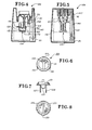
- Figures 6, 7 and 8 are, respectively, plan, side and bottom views of an incubator cap;
- Figure 9 is a diagrammatical illustration of baselining circuitry;
- Figure 10 is a diagrammatical illustration of the electrical circuitry or hybrid circuit;
- Figure 11 is a truth table showing the decoder algorithm used in the incubation assembly;
- Figure 12 is a plan view of the top of a transparent cuvette;
- Figure 13 is an irregular cross-sectional view taken along the line 13-13 of Figure 12;
- Figure 11 is a bottom view of the transparent cuvette of Figure 12;
- Figure 15 is a cross-sectional view taken along the line 15-15 of Figure 12;
- Figure 16 is a plan view of the bottom of the transparent cuvette;
- Figure 17 is a cross-sectional view taken along the line 17-17 of Figure 16;
- Figure 18 is a bottom view of the transparent cuvette bottom of Figure 16;
- Figure 19 is a cross-scctional view taken along the line 19-19 of Figure 16; and
- Figure 20 is a partial cross-sectional view of an alternate embodiment of the present invention.
- To satisfy the requirements of 35 U.S.C. §101, that to be patentable an invention must be useful, the combined cuvette with integral optical elements and electrical circuit with photoemissive and photosensitive elements in intimate optical contact with the optical elements of the present invention will be taught as being useful in a self-sufficient incubation assembly; however, it will be understood that the present invention is not so limited and that the present invention is limited ; only by the scope of the claims and the prior art. Referring now to FIGS. 1 to 12, there is illustrated a self-sufficient incubation assembly in which the present invention is useful, the incubation assembly is embodied in the manner taught in detail below, as a self-sufficient urinary tract infection kit for indicating the presence of a Gram negative infection, a Gram positive infection, or the absence of both.
- Referring now specifically to FIGS. 1-5, and initially to FIG. 1, the self-sufficient incubation assembly is indicated by general
numerical designation 100. The assembly includes abottom 101 and atop 102, which are essentially shell-like structures, assembled together and provided with required structural ; rigidity by telescopically interconnectingposts posts posts posts assembly 100 further includes atransparent cuvette 110 providing a first cell 111 and asecond cell 112, each cell for receiving a portion of a seeded liquid culture growth medium such as eugonic broth seeded with a urine sample from a urinary tract suspected of having a urinary tract infection such as a Gram negative or.Gram positive infection. - The
assembly 100 further includes an insulator, of suitable material, indicated by generalnumerical designation 116 and the two blocks shown in dashed outline in FIGS. 2, 4, and 5; theinsulator 116 provides a chamber.120 for receiving thetransparent cuvette 110 and insulates the cuvette and seeded liquid culture growth medium received therein during cultivation or incubation. It will be understood that for desired insulation the walls of thechamber 120 for receiving thecuvette 110 must be complementary to the external configuration of the cuvette and such is the case in the assembly, and hence it will be understood that thechamber 120 is coincident with the line defining the exterior of the cuvette and hence no physicallydistinct chamber 120 is shown. Further, it will be understood that since theeuvette 110 is of irregular confuguration, theinsulator 116 is made in two peeces, suitably shaped and assembled together, to provide the intimate contact betweon the insulator and the cuvette for desired insulation. - Electrical circuitry, as indicated by general
numerical designation 130, is included and, is in intimate physical contact with the under side of thetransparent cuvette 110 to provide intimate thermal and optical contact between the electrical circuitry and cuvette. Theelectrical circuitry 130, as may be best understood from the diagrammatical illustration of FIG. 10, may include amonolithic chip 132, afilm heating resistor 133 for heating thecuvette 110 and seeded culture growth medium received therein to a physiological temperature for the cultivation of microorganisms such as bacteria, a filmtemperature calibrating resistor 134, a temperature sensing element such asthermistor chip 135 for controlling theheat resistor 133 and thereby controlling to the desired physiological temperature the heat applied to the cuvette and the seeded culture growth medium received therein, a first photoemitter and photodetector pair El and Dl, a second photoemitter and photodetector pair E2 and D2, and additional photoemitters E3, E4 and E5. For example, thesubstrate 131 may be of a melamine fiberglass base, a porcelainized metal base, or a ceramic substrate. The photoemitters and photodetectors may be suitable available emitter and detector dies suitably bonded to the substrate at appropriate locations as shown; the film resistors may be suitably available such resistors and also suitably deposited on the substrate at appropriate locations as shown; thethermistor chip 135 may be a suitable available semi- conductor thermistor chip suitably bonded to the substrate as shown; and themonlithie chip 132 may be made of any one of several methods known to the prior art and may be made to embody, in combiation with the pairs of photoemitters and phtodetectors E1 and Dl and E2 and D2, a photometer, such as a turbidity meter, and further embody circuitry for baselining the photometer, temperature monitoring of the cuvette, indicator light illumination of the photoemitters E3, E4 and E5, as well as temperature control of the seeded culture growth medium during cultivation or incubation of the microorganisms or bacteria. Themonolithic chip 132 also may be suitably bonded to thesubstrate 131 and interconnected to the other electrical elements via bonding wires in the manner well known to those skilled in the art. - The
assembly 100 also includes an optical system for providing an external indication of the growth of the microorganisms or bacteria within the closed interior of the self-sufficient incubation assembly. This may be best understood by reference to FIGS. 5 and 10, where three electro-optical guides Gl, G2 and G3 are shown in physical and electro-optical registration and communication with thephotoemitters E3, E4 and E5, respectively, and communicate illumination emanating from these photoemitters to the exterior of the assembly to provide an external visual indication of the detection of growth of microorganisms or bacteria deep within the closed exterior of the assembly. The electro-optical light guides Gl, G2 and G3 may be supported and positioned, for example, by suitable complementary shaped guideways formed in theinsulator 16. - Referring now more specifically to the structure of the
transparent cuvette 110, as may be noted generally from reference to FIGS. 2 and 4, the cuvette is comprised of atop 160 and abettom 170 each made of suitable transparent material, such as a suitable transparent moldable plastic, and adhered together by a suitable adhesive or bonding operation; the irregular configuration and closed container aspect of thecuvette 160 require, for cost and convenience of manufacture, that it be made in two pieces, namely thetop 160 andbottom 170,and thereafter assemble. Referring specifically to FIGS. 12-15 and the specific structure of thecuvette top 160, it will be noted that the top is provided with a pair of upwardly extending intake orentrance galleries venting galleries venting gallery entrance gallery 162 andventing gallery 164 are associated withcuvette cell 112; hence, theentrance gallery 161 andventing gallery 163 operate as a pair and theentrance gallery 162 andventing gallery 164 operate as a pair. As may be best understood by reference to FIG. 15, and with regard tocell 112, the upper surface of the cell, provided by thelower surface 165 of thetop 160, is inclined or angled to insure venting upon filling of the cell.with a seeded culture growth liquid medium and in a manner explained in detail later,reflector 166, such as a strip of shiny metal or tape or other suitable surface treatment, is suitably adhered to thetop 165 to reflect light from the photoemitter E2 to the photodetector D2; it will be understood that cell 111 is also provided with an inclined top and areflector 167 as shown in FIG. 14; thereflector 167 is for roflection light from the photoemitter El to the photodetector Dl. - The
cuvette bottom 170, as shown in detail in FIGS. 14-19, is provided with a plurality of integrally formed, upwardly extending walls 171-176 defining cuvette cells 111-112 and thespace 112 therebetween. Thebottom 170 further includes upwardly extending integrally forred meniscus collimatinglens meniscus collecting lens collimating lens 181 and collectinglens 183 are associated with cuvette cell 111 and hence operate as a pair and that collimatinglens 182 and collectinglens 184 are associated withcuvette cell 112 and hence operate as a pair; it will be still further understood that collimatinglens 181 and collectinglens 183 operate or function in cooperation withreflector 167 and that collimatinglens 182 and collectinglens 184 operate or function in cooperation withreflector 166 as shown in FIG. 25. As is further shown in FIG. 19, the respective axes of the collimating and collectinglens reflector 166 is positioned upon assembly of the cuvette top and bottom) such that a beam or ray of light collected bylens 182 from photoemitter E2 is focused on thereflector 166 and the reflector reflects the received light along the axis of thecollimating lens 184 to the photo- detector D2, similarly with regard to collimating and collectinglens reflector 167 and photoemitter El and photodetector D1. Thebottom 170 is provided with locating pins 188- 189 to establish proper registration of thecuvette 110 with theelectrical circuitry 130. - The self-sufficient incubation assembly may also be provided with a cap indicated by general
numerical designation 150 and which cap is shown in detail in FIGS. 6-8. Generally,cap 150 has a dual function, namely it seals or closes thecuvette 110 upon a seeded liquid culture growth medium being received therein for microorganism cultivation and also interconnects theelectrical circuitry 130 with thebattery 144, Specifically, and referring to FIGS. 6-8, the cap includes atop 151, a plurality of radially disposed and downwardly extendingmembers top 102 of theassembly 100 as may be best seen in the upper lefthand portion of FIG. 8. Additionally, thecap 150 is provided with a pair of downwardly extendingplug members entrance galleries cap 150 has two positions, the first position with thearrow 159 of the cap (FIG. 6) not aligned with thearrow 119 provided on the top of the assembly as shown in FIG. 1 and in this position the cap does not interconnect theelectrical circuitry 130 with thebattery 144 and the cap is not locked to theassembly 100. However, upon the seeded liquid culture medium being placed in thecuvette 110 and operation of the assembly being desired, the cap is rotated 180° to align thearrows plug members entrance galleries resilient member 152, as shown, to lock thecap 150 to thetop 102 of theassembly 100 to close and seal the assembly for incubation. Additionally, upon thearrows member 155, as may be best seen in FIG. 4, engages a spring mountedelectrical connector 181 to foxce the connector into engagement with thebattery 144 to interconnect thebattery 144 through theclectrical connoctor 183 to theelectrical circuitry 130 to energize the circuit and commence incubation. ; - Referring again to FIG. 2, and to the upper lefthand portion, it will be understood that the
top 112 is formed inwardly to provide areceptacle 200 which is provided at its bottom with an integrally molded pair offunnels 201 and 202 ! aligned vertically with theentrance galleries cuvette 110. - The operation of the self-
sufficient incubation assembly 100, and the present invention will now be described for use as a urinary tract infection kit although it will be understood by those skilled in the art that the present invention is not so limited but is of general use. As is further known to those skilled in the art, bacteria can be classified into two groups, Gram negative and Gram positive bacteria. As is further known to those skilled in the art, urinary tract infection is caused primarily by Gram negative bacteria such as Ecoli; however, as is also known, urinary tract infection can be caused by Gram positive bacteria. While virtually all sampled urine contains some bacteria, the levels of bacteria of concern are those levels which are referred to in the art as clinically relevant levels of bacteria, for example 100,000 bacteria per ml, and it is the early detection of the presence of such clinically significant levels of bacteria that is the purpose of urinary tract infection detection apparatus in order that appropriate antibiotics can be prescribed and taken before the onset of a virulent bacterial infection. - As is further known to those skilled in the art, Gram negative bacteria reproduce facter, than Gram positive bacteria, Gram negative bacterin a reproducing approximrtely every 20 minutes while Gram positive bacteria reproduce approximately every 40 minutes, that is at approximately one half the rate of Gram negative bacteria. Hence, with this reproduction information, bacteria in a urine sample from a urinary tract suspected of having an infection may be cultivated at a physiological temperature, such as for example 37°C or 98.6°F, for a given period of time such as for example approximately four hours, and the bacteria level present at the beginning of the period per ml may be compared with the bacteria present per ml at the end of the period and the presence or absence of a clinically significant level of bacteria can be determined. In addition, by knowing the respective reproduction rates of Gram negative and Gram positive bacteria, and by comparing the respective growths of such bacteria over the time interval, the logical determination of the presence of a Gram negative infection or of a Gram positive infection can also be determined or clinically inferred.
- As is further known to those skilled in the art, the growth of bacteria in a sample, such as a seeded liquid culture growth medium, over a given period of time can be determined or measured by the use of a photometer such as a turbidity meter. I At the heginning of the time interval, the optical density of the sample can be measured by passing a transilluminating beam or ray of light through the sample and the energy loss due to light scattering of the beam can be measured and recerded. Bacteria, as is known, upon growth or reproduction scatters light and as bacteria in the sample reproduce or proliferate such as in response to cultivation, more light is scattered there:- by further increasing the optical density of the sample and hence at the end of the time interval the transilluninating beam er ray can again be passed through the sample and the inereased energy loss caused by increased optical density or light scattering can again be measured and compared vis-a-vis the earlier measurement. The difference in energy level of the light beam can be used, empirically, and particularly knowing the reproduction rate of the bacteria present, to provide a measurement of bacteria growth in the sample over the time interval. It will be further understood that circuitry embodied in the
monolithic chip 132 and the photoemitter and photodetector pairs El-Dl and E2-D2, in combination with the collimating and collecting lens and reflectors of thetransparent cuvette 110 function as a photometer or turbidity meter. - Referring now specifically to the operation of the present. invention when used in a urinary tract infection kit, it will be presumed that a urine sample has been taken from a urinary tract suspected of having a urinary tract infection, that the urine sample has been diluted in a suitable liquid culture growth medium, such as eugonic broth, to seed the broth, that the
cap 150 of theassembly 100 has been removed, and that the seeded liquid culture growth medium has been poured into thereceptacle 200 where it flows through the twofunnels 201, 202 where it substantially divides and enters into thecells 111 and 112 of thetransparent cuvette 110. It will be understood that cell 111 has been preconditioned to grow only Gram positive bacteria by having a Gram negative inhibitor placed therein such as by coating the walls of cell 111 with sodium azide powder which, as known to those skilled in the art, inhibits the growth of virtually all Gram negative bacteria. Howerer,cell 112 has not been so preconditioned and hence both Gram negative and Gram positive bacteria will grow incell 112. Thecap 150 will then be placed into thereceptacle 200 with thearrows electrical circuit 130 as taught above. It will be understood that themonolithic chip 132 of theelectrical circuitry 130, FIG. 10, may have a suitable circuit embodied therein to cause all of the photoemitters E3, E4 and E5 to be temporarily activated, or activated in a predetermined sequence, to provide indication to the user that the self-sufficient incubation assembly is functioning; thereafter such photoemitters will be extinguished and bacteria cultivation commenced and continued for a time interval. - As is further known to those skilled in the art, to provide significant turbidity measurements at the beginning and end of the time interval, the photometer or turbidity meter must be baselined to provide appropriate measurement references against which future measurements may be measured or compared for significant results. Accordingly, the
electrical circuitry 130 may be suitably baselined for significant measurements. Referring to FIG. 9, there is shown such baselining circuitry, indicated by general numerical designation 220; which may be used for such baselining, although illustrated as a block diagram in FIG. 9, it may be embodied in themonolithic chip 132 of FIG. 10 in a manner known to those skilled in the art. The baselining circuitry 220 I is a dual channelcircuit including channel 230 associated with cuvette cell 111 andchannel 240 associated withcuvette cell 112.Channel 230 includes the series connection of the photoemitter E1, photodetector D2, amplifier Al, switching network Sl, threshold comparater T1, start-stop logic 232, counter 234, digital to analog converter 23G and amplifier A2; similarly, thechamel 240 includes the scrips connected components as shown. Additionally, the baselining circuit includes the threshold comparators T3 and T4 connected to thedecoder 250 which in turn is provided with three outputs as shown, for providing one of three binary outputs indicative of the bacterial conditions shown, namely no infection, Gram negative infection, or Gram positive infection. - Continuing from above, it will again be presumed that the
circuitry 130 has been energized by thebattery 144 due to the closure of thecap 150 and now the operation of the baselining circuitry 220 and thedecoder 250 for providing the bacterial infection indication shown will be described. With regard tobaselining channel 230, upon energization the switching network BW1 assumes state S1 whereupon photoemitter E1 has no output and hence photodetector D1 has no input and therefore no output; this lack of output will be reflected to amplifier A1 and threshold comparator T1 will signal the start-stop logic 232 to initiate counting which is then converted, digital to analog by the converter 236, boosted by amplifier A2, and reflected in a gradually increasing light level emanating from the photoemitter E1. At such time the evoked response of the photodetector Dl reaches the preset level of threshold detector Tl, the start-stop logic is signalled to stop counting thus freezing the output level of the photoemitter El andchannel 230 is now baselined; similarly,channel 240 is also baselined to the preset level of the threshold detector T2. At the conclusion of the cultivation time interval, for example approximately four hours, which time elapse is built into the circuitry of themonolithic chip 132 in a manner known to thosa skilled in the art, the switching network SW1 assumes state S2 and the evoked response of the photodetector D1 in response to the output of the photoemitter E1 transilluminating the cuvette cell 111 is connected through amplifier A1 to threshold comparator T3 and compared with its preset threshold level and if the later evoked response of the photodetector D1 falls below the threshold of threshold comparator T3 a binary 0 signal is transmitted to thedecoder 250 to indicate the absence of clinically significant Gram positive bacteria growth in cell 111. However, if the evoked response of the photodetector Dl is at least equal to or greater than the preset threshold of threshold comparator D3, a binary 1 signal is transmitted to thedecoder 250 to indicate the presence of clinically significant Gram positive bacteria growth in cell 111. Similarly, threshold comparator T4 is preset to send a binary 0 or 1 signal to thedecoder 250 to respectively indicate the absence of clinically significant levels of Gram negative and/or Gram positive bacteria growth incell 112 or the presence of clinically significant levels of Gram negative and/or Gram positive bacterial growth incell 112. It will be understood that the preset threshold levels of the respective threshold comparators will be preset empirically and in accordance with the recognized respective reproduction and growth rates of Gram positive and Gram negative bacteria, for example the preset threshold of threshold comparator T4 ofchannel 240 will be approximately twice the preset level of threshold comparator T3 ofchannel 230 since it is known that Gram negative bacteria grow at appreximately twice the rate of Gram positive bacteria. Thedecoder 250 will interpret or decode the binary 1 or 0 signals received from the respective threshold comparators T3 and T4 to provide an indication of bacterial growth in accordance with the algorithm, sometimes referred to in the art as a truth-table, set forth in FIG. 11. It will be further understood that the algorithm or truth-table of FIG. 11 will also be embodied in suitable circuitry included in themonolithic chip 132 of theelectrical circuit 130. - Referring now to the decoder algorithm of FIG. 11, upon the
decoder 250 of FIG. 9 receiving the binary 1 from the output of cell 111 and a binary 0 from the output ofcell 112, this will be interpreted and the appropriate photoemitter E4 illuminated to indicate the presence of clinically significant levels of Gram positive bacteria in the urine sample. Upon the decoder receiving a binary 0 from cell 111 and a binary 1 fromcell 112, this will be interpreted by thedecoder 250 to indicate the presence of clinically significant levels of Gram negative bacterial and photoemitter E4 will be illuminated to provide such indication. Should a binary 0 be received from both cells, this will be decoded to indicate the absence of any clinically significant infection and photoemitter E3 will be illuminated to provide such visual indication. However, it is possible for the decoder to receive a binary 1 from both cell 111 andcell 112 and, as indicated in FIG. 17, this is interpreted or decoded by thedecoder 250 to indicate the presence of clinically significant levels of Gram positive bacteria. This results from one of two possible situations and the following logic: one possibility is that Gram positive bacteria were present in such large quantity or experienced such large growth during cultivation as to exceed both the preset threshold level ofthreshold comparator T3 of the Gram positive cell 111 and the preset threshold level of the threshold comparator T4 of the Gram positive and/or Gramnegative bacteria cell 112; the other possibility is that there were mixed bacteria present, indicating the possibility of a mixed infection, and that the growth of the gram positive bacteria incell 112 exceeded the threshold of threshold comparator T3 and that there was either mixed or Gram negative bacteria growth incell 112 sufficient to exceed the preset threshold of threshold comparator T4. In such event. as known to those skilled in the art, treatment for Gram positive bacteria or Gram positive infection is indicated. - It will be noted from FIGS. 2, 4, and 5, and from FIG. 10 where
cuvette 110, cell 111 andcell 112 are shown in dashed outline, that theelectrical circuitry 130 and thetemperature control element 135 are in intimate physical contact with thecuvette 110 specifically the underside thereof. Hence, the temperature of thetemperature control element 135 will be substantially the same as the temperature of the cuvette and the seeded culture growth medium contained therein whereby improved temperature control of the medium is provided, and the heat of operation of theelectrical circuitry 130 will supplement the heat applied by theheating resistor 133 andbattery 144 to thecuvette 110 and the seeded culture growth medium received therein whereby the energy required to be supplied by thebattery 144 will be less than would be required were theelectrical circuitry 130 to be located externally of the cuvette and not in intimate physical contact therewith. - Referring now to FIG. 20, there is shown an alternate embodiment of the present invention including a transparent cuvette indicated by general
numerical designation 210 in combination with an electrical circuit indicated diagrammatically by generalnumerical designation 230. Thecuvette 210 is provided with abottom portion 211, shown in cross-section, and including transparent sidewalls and bottom as shown, and being open at the top, but which may be provided with a transparent top portion substantially the same as one half of the top 160 of FIGS. 12-15 and provided with entrance and venting galleries such asgalleries transparent cuvette bottom 212 may be provided with integrally formed optical elements such as integrally formedmeniscus collimating lens 212 and integrally formedmeniscus collecting lens 214 and with their : respective axes aligned as indicated by thearrows 215 and 216 of FIG. 20 whereby no reflector is required. Theelectrical circuit 230, indicated diagrammatically, is functionally substantially the same as thecircuit 130, particularly as illustrated in FIG. 10, and insofar as is pertinent to an understanding of the alternate embodiment of FIG. 20 may be provided, inter alia, with aphotoemitter 232 and aphotodetector 233 in intimate optical contact with arespective lens 212 and 2.14 as illustrated, and a heating resistor indicated diagrammatically bynumerical designation 237. - As used in the specification and the appended claims, the expression "intimate optical contact" means that a photoemitter is positioned at a point with respect to its associated optical element to maximize the performance of the ray emanating from the photoemitter and passing through the associated optical element for the intended purpose of the ray and that a photodetector is positioned at a point with respect to its associated optical element to maximize the performance of the ray received and passing through the associated optical element for the intended purpose of the ray; e.g. the photoemitter El of FIG. 10 and
photoemitter 232 of FIG. 20 are positioned at the proper point along the optical axis of therespective collimating lens 181 of thecuvette 110 andcollimating lens 212 ofcuvette 210 to maximize collimation of the light emitted by the photodetector for transilluminating the culture growth medium received by therespective cuvette photodetector 233 of FIG. 20 are positioned along the optical axis of therespective collecting lens respective cuvette - It will be further understood by those skilled in the art that many modifications and variations of the present invention may be made without departing from the spirit and the scope thereof.
Claims (4)
Priority Applications (2)
| Application Number | Priority Date | Filing Date | Title |
|---|---|---|---|
| DE8484114063T DE3477609D1 (en) | 1984-11-22 | 1984-11-22 | Combined cuvette with integral optical elements and electrical circuit with photoemissive and photosensitive elements in intimate optical contact with said optical elements |
| EP84114063A EP0186712B1 (en) | 1984-11-22 | 1984-11-22 | Combined cuvette with integral optical elements and electrical circuit with photoemissive and photosensitive elements in intimate optical contact with said optical elements |
Applications Claiming Priority (1)
| Application Number | Priority Date | Filing Date | Title |
|---|---|---|---|
| EP84114063A EP0186712B1 (en) | 1984-11-22 | 1984-11-22 | Combined cuvette with integral optical elements and electrical circuit with photoemissive and photosensitive elements in intimate optical contact with said optical elements |
Publications (2)
| Publication Number | Publication Date |
|---|---|
| EP0186712A1 true EP0186712A1 (en) | 1986-07-09 |
| EP0186712B1 EP0186712B1 (en) | 1989-04-05 |
Family
ID=8192295
Family Applications (1)
| Application Number | Title | Priority Date | Filing Date |
|---|---|---|---|
| EP84114063A Expired EP0186712B1 (en) | 1984-11-22 | 1984-11-22 | Combined cuvette with integral optical elements and electrical circuit with photoemissive and photosensitive elements in intimate optical contact with said optical elements |
Country Status (2)
| Country | Link |
|---|---|
| EP (1) | EP0186712B1 (en) |
| DE (1) | DE3477609D1 (en) |
Cited By (1)
| Publication number | Priority date | Publication date | Assignee | Title |
|---|---|---|---|---|
| EP0653620A1 (en) * | 1993-10-26 | 1995-05-17 | Siemens Aktiengesellschaft | Optical sensor |
Citations (3)
| Publication number | Priority date | Publication date | Assignee | Title |
|---|---|---|---|---|
| US3718439A (en) * | 1970-06-12 | 1973-02-27 | Instrumentation Labor Inc | Analytical apparatus |
| FR2297414A1 (en) * | 1975-01-09 | 1976-08-06 | Inst Nat Sante Rech Med | Photometric absorption radiometer for gases or fluid - has photoresistance, photodiode, photo transistor or avalanche transistor as receiver |
| US4083638A (en) * | 1975-08-27 | 1978-04-11 | Technicon Instruments Corporation | Cuvette and method of use |
Family Cites Families (1)
| Publication number | Priority date | Publication date | Assignee | Title |
|---|---|---|---|---|
| US4565446A (en) * | 1982-09-29 | 1986-01-21 | The Research Foundation Of State University Of New York | Scattering cells |
-
1984
- 1984-11-22 DE DE8484114063T patent/DE3477609D1/en not_active Expired
- 1984-11-22 EP EP84114063A patent/EP0186712B1/en not_active Expired
Patent Citations (3)
| Publication number | Priority date | Publication date | Assignee | Title |
|---|---|---|---|---|
| US3718439A (en) * | 1970-06-12 | 1973-02-27 | Instrumentation Labor Inc | Analytical apparatus |
| FR2297414A1 (en) * | 1975-01-09 | 1976-08-06 | Inst Nat Sante Rech Med | Photometric absorption radiometer for gases or fluid - has photoresistance, photodiode, photo transistor or avalanche transistor as receiver |
| US4083638A (en) * | 1975-08-27 | 1978-04-11 | Technicon Instruments Corporation | Cuvette and method of use |
Cited By (1)
| Publication number | Priority date | Publication date | Assignee | Title |
|---|---|---|---|---|
| EP0653620A1 (en) * | 1993-10-26 | 1995-05-17 | Siemens Aktiengesellschaft | Optical sensor |
Also Published As
| Publication number | Publication date |
|---|---|
| DE3477609D1 (en) | 1989-05-11 |
| EP0186712B1 (en) | 1989-04-05 |
Similar Documents
| Publication | Publication Date | Title |
|---|---|---|
| US4577970A (en) | Cuvette with integral optical elements | |
| US4619530A (en) | Combined cuvette with integral optical elements and electrical circuit with photoemissive and photosensitive elements in intimate optical contact with said optical elements | |
| US4666853A (en) | Self-sufficient incubation assembly | |
| US5001417A (en) | Apparatus for measuring electrolytes utilizing optical signals related to the concentration of the electrolytes | |
| US5164796A (en) | Apparatus and method for detection of microorganisms | |
| US3895661A (en) | Cuvette apparatus for testing a number of reactants | |
| CA1278703C (en) | Analytical apparatus | |
| US7108966B2 (en) | Male fertility assay method and device | |
| EP0811154B1 (en) | Fluorescent optical sensor | |
| US4294931A (en) | Device for conducting microbiological radiorespirometric assays | |
| EP0182926B1 (en) | Self-sufficient incubation assembly | |
| US3837746A (en) | Apparatus for evaluation of biological fluid | |
| WO2011030983A1 (en) | Portable digital reader for urinalysis | |
| IL49469A (en) | Photometric apparatus | |
| US7002688B2 (en) | Multilens optical assembly for a diagnostic device | |
| CN108663303A (en) | A kind of blood analyser | |
| USRE28801E (en) | Apparatus for evaluation of biological fluid | |
| EP0472622B1 (en) | Apparatus for detection of microorganisms | |
| EP0181962B1 (en) | Cuvette with integral optical elements | |
| US4013368A (en) | Sample cartridge for use in apparatus for evaluation of biological fluid | |
| EP0186712A1 (en) | Combined cuvette with integral optical elements and electrical circuit with photoemissive and photosensitive elements in intimate optical contact with said optical elements | |
| Wendel et al. | Rapid diagnosis of maple syrup urine disease (branched chain ketoaciduria) by micro-enzyme assay in leukocytes and fibroblasts | |
| CN208420635U (en) | A kind of blood analyser | |
| WO1988007584A1 (en) | Method and apparatus for detection and quantification of bacteria | |
| JP2004520593A (en) | How to maintain test consistency in microbial test arrays |
Legal Events
| Date | Code | Title | Description |
|---|---|---|---|
| PUAI | Public reference made under article 153(3) epc to a published international application that has entered the european phase |
Free format text: ORIGINAL CODE: 0009012 |
|
| 17P | Request for examination filed |
Effective date: 19851010 |
|
| AK | Designated contracting states |
Kind code of ref document: A1 Designated state(s): CH DE FR GB IT LI NL SE |
|
| 17Q | First examination report despatched |
Effective date: 19880201 |
|
| GRAA | (expected) grant |
Free format text: ORIGINAL CODE: 0009210 |
|
| AK | Designated contracting states |
Kind code of ref document: B1 Designated state(s): CH DE FR GB IT LI NL SE |
|
| PG25 | Lapsed in a contracting state [announced via postgrant information from national office to epo] |
Ref country code: SE Effective date: 19890405 Ref country code: NL Effective date: 19890405 Ref country code: LI Effective date: 19890405 Ref country code: IT Free format text: LAPSE BECAUSE OF FAILURE TO SUBMIT A TRANSLATION OF THE DESCRIPTION OR TO PAY THE FEE WITHIN THE PRESCRIBED TIME-LIMIT;WARNING: LAPSES OF ITALIAN PATENTS WITH EFFECTIVE DATE BEFORE 2007 MAY HAVE OCCURRED AT ANY TIME BEFORE 2007. THE CORRECT EFFECTIVE DATE MAY BE DIFFERENT FROM THE ONE RECORDED. Effective date: 19890405 Ref country code: CH Effective date: 19890405 |
|
| REF | Corresponds to: |
Ref document number: 3477609 Country of ref document: DE Date of ref document: 19890511 |
|
| ET | Fr: translation filed | ||
| REG | Reference to a national code |
Ref country code: CH Ref legal event code: PL |
|
| PGFP | Annual fee paid to national office [announced via postgrant information from national office to epo] |
Ref country code: FR Payment date: 19890721 Year of fee payment: 6 |
|
| PGFP | Annual fee paid to national office [announced via postgrant information from national office to epo] |
Ref country code: DE Payment date: 19890728 Year of fee payment: 6 |
|
| NLV1 | Nl: lapsed or annulled due to failure to fulfill the requirements of art. 29p and 29m of the patents act | ||
| PGFP | Annual fee paid to national office [announced via postgrant information from national office to epo] |
Ref country code: GB Payment date: 19891130 Year of fee payment: 6 |
|
| PLBE | No opposition filed within time limit |
Free format text: ORIGINAL CODE: 0009261 |
|
| STAA | Information on the status of an ep patent application or granted ep patent |
Free format text: STATUS: NO OPPOSITION FILED WITHIN TIME LIMIT |
|
| 26N | No opposition filed | ||
| PG25 | Lapsed in a contracting state [announced via postgrant information from national office to epo] |
Ref country code: GB Effective date: 19901122 |
|
| GBPC | Gb: european patent ceased through non-payment of renewal fee | ||
| PG25 | Lapsed in a contracting state [announced via postgrant information from national office to epo] |
Ref country code: FR Effective date: 19910731 |
|
| PG25 | Lapsed in a contracting state [announced via postgrant information from national office to epo] |
Ref country code: DE Effective date: 19910801 |
|
| REG | Reference to a national code |
Ref country code: FR Ref legal event code: ST |