EP0185808A1 - Automatic parenteral infusion apparatus - Google Patents
Automatic parenteral infusion apparatus Download PDFInfo
- Publication number
- EP0185808A1 EP0185808A1 EP84308682A EP84308682A EP0185808A1 EP 0185808 A1 EP0185808 A1 EP 0185808A1 EP 84308682 A EP84308682 A EP 84308682A EP 84308682 A EP84308682 A EP 84308682A EP 0185808 A1 EP0185808 A1 EP 0185808A1
- Authority
- EP
- European Patent Office
- Prior art keywords
- pressure
- infusion
- liquid
- bladder
- container
- Prior art date
- Legal status (The legal status is an assumption and is not a legal conclusion. Google has not performed a legal analysis and makes no representation as to the accuracy of the status listed.)
- Granted
Links
Images

Classifications
-
- A—HUMAN NECESSITIES
- A61—MEDICAL OR VETERINARY SCIENCE; HYGIENE
- A61M—DEVICES FOR INTRODUCING MEDIA INTO, OR ONTO, THE BODY; DEVICES FOR TRANSDUCING BODY MEDIA OR FOR TAKING MEDIA FROM THE BODY; DEVICES FOR PRODUCING OR ENDING SLEEP OR STUPOR
- A61M5/00—Devices for bringing media into the body in a subcutaneous, intra-vascular or intramuscular way; Accessories therefor, e.g. filling or cleaning devices, arm-rests
- A61M5/14—Infusion devices, e.g. infusing by gravity; Blood infusion; Accessories therefor
- A61M5/142—Pressure infusion, e.g. using pumps
- A61M5/145—Pressure infusion, e.g. using pumps using pressurised reservoirs, e.g. pressurised by means of pistons
- A61M5/155—Pressure infusion, e.g. using pumps using pressurised reservoirs, e.g. pressurised by means of pistons pressurised by gas introduced into the reservoir
-
- Y—GENERAL TAGGING OF NEW TECHNOLOGICAL DEVELOPMENTS; GENERAL TAGGING OF CROSS-SECTIONAL TECHNOLOGIES SPANNING OVER SEVERAL SECTIONS OF THE IPC; TECHNICAL SUBJECTS COVERED BY FORMER USPC CROSS-REFERENCE ART COLLECTIONS [XRACs] AND DIGESTS
- Y10—TECHNICAL SUBJECTS COVERED BY FORMER USPC
- Y10S—TECHNICAL SUBJECTS COVERED BY FORMER USPC CROSS-REFERENCE ART COLLECTIONS [XRACs] AND DIGESTS
- Y10S128/00—Surgery
- Y10S128/12—Pressure infusion
Landscapes
- Health & Medical Sciences (AREA)
- Vascular Medicine (AREA)
- Engineering & Computer Science (AREA)
- Anesthesiology (AREA)
- Biomedical Technology (AREA)
- Heart & Thoracic Surgery (AREA)
- Hematology (AREA)
- Life Sciences & Earth Sciences (AREA)
- Animal Behavior & Ethology (AREA)
- General Health & Medical Sciences (AREA)
- Public Health (AREA)
- Veterinary Medicine (AREA)
- Infusion, Injection, And Reservoir Apparatuses (AREA)
Abstract
Description
- This invention relates to apparatus for automatic parenteral infusion of a liquid. More particularly, the invention relates to infusion apparatus in which the liquid to be infused into a patient is supplied at a relatively constant pressure to provide a constant, predetermined rate of infusion.
- In the medical field, there is frequent need to introduce various liquids into the patient's body. Two techniques are commonly practiced but each suffer drawbacks under varying circumstances.
- First, the liquid may be loaded into a conventional syringe and administered to the patient as a single injection through a hypodermic needle. As one example, diabetics may be supplied insulin using this technique. Medical science has determined, however, that it is frequently beneficial in health care to administer various medicinal liquids not at one time in a single dose, but at a slow rate over a prolonged period of time.
- Such recognition gave rise to the second widely practiced technique for introducing liquids to a patient. Liquids such as saline solutions, plasma, whole blood and the like may be administered to a patient by inserting a needle into the patient's body and hanging a bottle or bag of the solution above the level of the patient so that the liquid is infused into the patient under positive pressure via flexible tubing connecting the bottle or bag and the needle. These parenteral liquid containers are typically elevated two to three feet above the patient and may be supported from a pole fastened to the patient's bed. This technique suffers fran the obvious disadvantage that the patient's mobility is limited.
- Oftentimes in the emergency treatment of trauma patients, intravenous solutions, for example, must be administered at the accident scene or while the patient is in route to medical facilities. Under these circumstances, the requirement of having an elevated intravenous container above the patient often presents difficulties because there is no provision for hanging the container. Thus, medical personnel must accompany the patient in order to hold the intravenous container at an appropriate, elevated position. In ambulances, helicopters, and similar medical evacuation vehicles, it may be difficult to properly position the intravenous bottle. Variations in height of the intravenous bottle above the patient will affect the pressure head of liquid and thus vary the flow rate of the solution to the patient.
- To overcome the requirement of having to elevate an intravenous (IV) bottle, various apparatus have been proposed in which a flexible IV bag is pressurized either by gas pressure or by mechanical force. However, as the IV solution drains from the IV bag, the pressure force exerted on the bag also decreases thus lowering the pressure on the IV solution. This is the same problem encountered in varying the height of the bottle above the patient. To overcome this changing pressure problem, some of the known pressurized IV apparatus have a squeeze bulb which must be manually operated to increase the pressure on the IV bag as the IV solution empties therefrom. In other known pressurized IV apparatus, compressed gas from a source of compressed gas is regulated by means of a pressure regulator to maintain contant pressure on the IV bag. However, the requirement of a compressed gas source and a regulator appreciably increases the cost and complexity of the IV apparatus and, thence, the possibility of malfunction it increased.
- The foregoing teachings of the prior art are embraced in the following patents.
- U. S. Patent 2,842,123 of Rundhaug, issued July 8, 1958 and entitled "Pressurized Tranfusion Apparatus", discloses a pressurized tranfusion apparatus having a sealed pressure container connected to a compressed gas source and having a collapsible tranfusion bag within the pressure container whereby the gas pressure acts directly on the bag to pressurize the liquid therein and to force delivery to the patient.
- U. S. Patent 3,153,414 by Beall et al, issued October 20, 1964 and entitled "Apparatus for the Induced Infusion of Liquid from a Flexible Liquid Container", discloses infusion equipment in which an inflatable bladder encircles an intravenous liquid bag. The bladder is inflatable by a manually operated inflation squeeze bulb and exerts pressure on the intravenous bag to force fluid to the patient.
- U. S. Patent 3,468,308 of Bierman, issued September 23, 1969 and entitled "Pressure Infusion Device for Ambulatory Patients with Pressure Control Means", teaches a collapsible bag contained within a rigid pressure shell equipped with a pressure regulating device to insure constant pressure and thus control delivery rate of intravenous liquid.
- U. S. Patent 3,507,278 of Werding, issued April 21, 1970 and entitled "Apparatus for Dispensing Parenteral Fluid", teaches transfusion apparatus in which a bag of liquid to be administered is contained within a rigid sealed vessel and is pressurized by gas pressure within the sealed vessel from a remote canpressed gas source.
- U. S. Patent 3,838,794 by Cogley et al, issued October 1, 1974 and entitled "Package for Storing and Dispensing Liquids", teaches a collapsible IV bag contained within a pressurized bladder connected to a regulated source of compressed air.
- The teachings of the prior art, as exemplified by the foregoing references, have not been widely accepted in the medical field. As previously mentioned, gas regulating equipment adds to the cost and complexity of infusion apparatus of this genre. Medical personnel must be trained for the specific type of equipment being used and must be mindful of the varying techniques for regulating pressure on the IV solution. In spite of these significant drawbacks, however, an even more important problem exists in this equipment. It is, in fact, a potential health hazard. In the case of pressurized IV bags, the known prior art teaches pressurizing gas acting directly on the IV bag. In the event of a rupture of the IV bag, the pressurizing gas may enter the IV bag and ultimately be transmitted to the patient. The danger of air embolism is therefore thought to be the primary reason pressurized intravenous delivery equipment has not been widely utilized. Furthermore, a pressurizing gas desirable for its physical properties may be physiologically toxic if accidentally introduced to a patient due to equipment malfunction.
- Accordingly, a need remains in the medical field for automatic parenteral infusion apparatus which is safe and which overcomes the drawbacks heretofore experienced with similar equipment in this art. The primary goal of this invention is to meet this need.
- More particularly, an object of the invention is to provide pressurized, automatic parenteral infusion equipment which delivers parenteral solution at a predetermined and substantially constant rate and which includes features preventing the danger of toxicity or air embolism to the patient.
- Yet another object of the invention is to provide automatic parenteral infusion equipment for administering parenteral solution Which does not require Lhe equipment to be elevated above the level of the person. Thus, the equipment is particularly useful in the field of emergency medical treatment.
- A further object of the invention is to provide automatic infusion equipment of the character described Which administers parenteral solution at a substantially constant regulated flow regardless of the amount of parenteral solution in the supply source. Thus eliminated is the need of continuous regulation and monitoring of the equipment by medical personnel. As a corollary advantage, the equipment is easily utilized by medical personnel accustomed to administering parenteral solutions with conventional equipment and without requiring any special training for such personnel.
- Another object of the invention is to provide automatic parenteral infusion equipment of the character described which is fully self contained and portable to facilitate both storage and simplicity of use. Both disposable and reusable adaptations of the equipment may be utilized under varying circumstances.
- An additional object of the invention is to provide safe and convenient parenteral equipment of the character described being portable and having features particularly suitable for ambulatory patients. Thus, a user may actually carry on the body equipment embodying this invention to deliver parenteral medication over an extended period of time.
- Other and further objects of the invention, together with the features of novelty appurtenant thereto, will appear in the course of the following description of the drawings.
- In the accompanying drawings which form a part of the specification and are to be read in conjunction therewith, and in which like reference numerals are employed to indicate like parts in the various views:
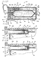
- Fig. 1 is a sectional, side elevational view of automatic infusion apparatus illustrating a first embodiment of the invention with portions of the delivery tube broken but indicating continuous length;
- Fig. 2 is a sectional, side elevational view of parenteral infusion apparatus illustrating a second embodiment of the invention;
- Fig. 3 is a sectional, side elevational view of automatic infusion apparatus illustrating a third embodiment of the invention;
- Fig. 4 is an enlarged fragmentary view, partly in section, illustrating the flow regulating fluid delivery mechanism;
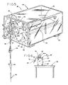
- Fig. 5 is a perspective view of automatic parenteral infusion apparatus illustrating a fourth embodiment of the invention;
- Fig. 6 is a side elevational view of the automatic parenteral infusion apparatus in a typical operational setting;
- Fig. 7 is a longitudinal side sectional view of the infusion apparatus shown in Fig. 5;
- Fig. 8 is an enlarged fragmentary view of a portion of the apparatus shown in Fig. 7 illustrating means for effecting pressurization of the liquid in the parenteral bag with the pressurizing means being illustrated in a ready to use configuration;
- Fig. 9 is a view similar to that of Fig. 8, but showing the pressurizing means shifted to an activated configuration; and
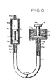
- Fig. 10. is a sectional, side elevational view of automatic infusion apparatus illustrating a fifth embodiment of the invention.
- Referring to the drawings in more detail, attention is first directed to Fig. 1. The automatic parenteral infusion apparatus includes a
cylindrical container shell 10 constructed of a rigid, and preferably, translucent material. Theshell 10 is necked down at thelower end 10a thereof and capped with atubing connector cap 11. Parenteralliquid delivery tubing 12 sealingly penetratesconnector cap 11 to communicate with the interior of thecontainer 10. Thetubing 12 may be of any suitable length as indicated by the discontinuous lines in Fig. 1 and is equipped with an on/offflow control valve 13. The terminal end of thetubing 12 is fitted with a taperedhollow nozzle 14. As best shown in Fig. 4, thenozzle 14 is positioned within the socket of aflow regulating member 15 having a preselectedlysized orifice 15a therethrough. Removably fitted to the outer end of theflow regulating member 15 is ahypodermic needle 16 to penetrate a patient's body for the delivery of parenteral fluid. - Within the
shell 10 is formed a chanber for containing the parenteral fluid designated by the letter F. Thechamber 10b containing fluid F is defined by the interior wall surfaces ofshell 10 extending from the necked downportion 10a sealed withcap 11 to amovable plug 17 which sealingly engages the interior cylindrical wall of theshell 10. Thus, theplug 17 bears against the upper surface of the fluid F in the equipment as oriented in Fig. 1. Surmounting theplug 17 is anexpandable gas bladder 18 having accordion-like pleats 18a forming the cylindrical side surface thereof to permit expansion of thebladder 18 through the length of theshell 10. Contained within the upper end of theshell 10 is a replaceablepressure source cannister 19. Thecannister 19 has cylindrical side walls with an outside diameter slightly less than the inside diameter of theshell 10 to define an annulus 10f therebetween. The lower end wall of thecannister 19 is fitted with ahollow needle member 19a adapted to sealingly penetrate thegas bladder 18. The upper end of thecannister 19 is substantially the same diameter as the outside diameter of theshell 10 to overlie the upper edge thereof to properly seat thecannister 19 in the end of theshell 10. Thecannister 19 is held in place by a removable cap 10c secured to theshell 10 by threads, a compression gasket, or a similar connection to enable the cap 10c to be removably locked in place on theshell 10. - The
cap 10b may be equipped with a hanger wire 10d for suspending the apparatus as shown in Fig. 1. Alternatively, it should be understood that it is not necessary that the equipment be vertically oriented as shown in Fig. 1. Indeed, it may be oriented in virtually any position since delivery of the fluid F to the patient does not rely upon gravity flow. - Between the upper end of the
shell 10 and themovable plug 17 are a plurality ofopenings 10e which provide atmospheric canmunication with the interior of thecontainer shell 10. The uppermostsuch opening 10e is positioned adjacent the annulus 10f. The purpose of such openings will be understood shortly. - A pressuring fluid P is contained within the
pressure source cannister 19. Preferably, the pressurizing fluid P is a liquid which has a boiling point at atmospheric pressure below room temperature (i.e., below 70°F.), and preferably well below normal ambient temperatures. For example, ethyl chloride having a boiling point at 54°F., at ambient pressure may be selected as pressurizing fluid P. Those skilled in the art will of course recognize that other fluids, such as certain fluorohydrocarbon refrigerants, may also be used as the pressurizing fluid P. - So constructed and assembled, the pressurizing fluid P within
cannister 19 communicates through theneedle member 19a to theexpandable bladder 18 to exert a pressure therein substantially equal to the vapor pressure of fluid P at ambient conditions. Thebladder 18 expands to fill the space between the lower surface of thecannister 19 and the upper surface of themovable plug 17. Further expansion of thebladder 18, forces theplug 17 to pressurize the parenteral tiuid F which is delivered through thetubing 12 and theflow regulating member 15 to the patient via thehypodermic needle 16. Flow is thus regulated, in accordance with the recognized principles of fluid mechanics, by the substantially constant pressure source of theexpandable bladder 18 and theorifice size 15a of theflow regulating device 15. - In the event of rupture or leakage from the
cannister 19 or thebladder 18, the pressure fluid P is safely vented to the atmosphere throughopenings 10e. - Referring to Fig. 2 of the drawings, alternative features of the invention are illustrated. The parenteral liquid container in the form of a rigid,
cylindrical shell 20 having aneck 20a on one end thereof with a fluid passageway communicating with the interior of the container. The upper end of theshell 20 is sealed by anend plate 20b. Interiorly of the container is achamber 20c for the parenteral fluid F Which is separated from thechamber 20d pressure fluid P by aspool piece 21. Thespool piece 21 is formed by upper and lowermovable plugs 21a and b sealingly engaged with the interior cylinder wall of theshell 20 and centrally interconnected by anaxial rod 21c. Intermediate thefluid chamber 20c and thepressure source chamber 20d, theshell 20 is provided with a plurality ofopenings 20e therein communicating with the atmosphere. - In operation, constant pressure supplied by the pressure fluid P is transmitted through the
spool piece 21 to the fluid F Which is delivered through tubing (not shown) of the character as previously described until the.fluid F is fully discharged. The latter condition is illustrated as a broken line view of thespool piece 21 in Fig. 2. - In the event of defect or leakage of pressure around the
upper sealing plug 21a, the pressure fluid P will be vented to the atmosphere through theopenings 20e in the shell wall to prevent embolism or introduction of toxics to the patient. - Referring to Fig. 3 of the drawings, further modifications of the invention are illustrated in a third embodiment. The container is formed of a rigid,
cylindrical shell 30 having aneck 30a with a central opening therethrough. Interiorly of the chamber is acollapsible bag 31 charged with parenteral fluid F. Anexpandable bladder 32 surmounts thebag 31. Thebladder 32 has accordion-like pleats forming the cylindrical side thereof to permit expansion of thebladder 32. The upper circular end wall 32a of thebladder 32 is immovably secured to the interior wall of theshell 30. Thus, defined between the bladder wall 32a and the upper end wall 30b of theshell 30 is apressure source chamber 30c charged with a pressurizing fluid P. Received within the end wall 30b of theshell 30 is apressure activating member 33 having a sharpened end 33a which penetrates in a sealing manner the upper end wall 32a of thebladder 32. Thepressure actuating member 33 includes aninterior bore 33b with spacedradial openings 33c therefran. When the actuatingmember 33 is fully depressed theuppermost openings 33c are positioned withinpressure chamber 30c and the lowermost set ofopenings 33c are positioned interiorly of thebladder 32 whereby communication is thus established throughbore 33b between thepressure chamber 30c and the interior of thegas bladder 32. - In operation, the actuating
plunger 33 is fully depressed to pressurize at a substantially constant pressure thebladder 32.Delivery tubing 12 is received by a fitting 34 having ahollow needle 34a received through theshell neck 30a to sealingly penetrate thebag 31. Expansion of thegas bladder 32 thus causes fluid F to be delivered at a constant rate to the patient through delivery equipment of the character as previously described. - Between the upper end of the
bag 31 when fully charged with fluid F and the upper immovable wall of thebladder 32, theshell 30 is provided with a plurality ofopenings 30d therein communicating with the atmosphere. In the event of a pressure leak or rupture of thegas bladder 32, the pressure fluid will be vented to the atmosphere through theopenings 30d in the shell wall to insure the patient's safety. - The embodiments of the invention so described with reference to the embodiments of Figs. 1-3 thus contemplate disposable and portable infusion equipment. Depending of course on the amount of parenteral fluid to be delivered to the patient, the equipment may be so sized as to be conveniently secured to the body of an ambulatory patient.
- Attention is now directed to the fourth embodiment of the invention which contemplates larger and rechargeable equipment which is portable yet, due to its capacity, is not designed to be secured to the patient's body. Reference is made to Figs. 5-9.
- A
flexible bag 40 contains a volume of parenteral fluid F to be infused into the patient's body. Thebag 40 has anoutlet 40a and a length oftubing 42 connected to the bag outlet. As generally indicated at 43, a hypodermic needle is connected to the free end of the tubing for insertion into the patient's body for the flow of fluid F frombag 40 to the patient. An adjustable valve orflow regulator 44 is provided alongtube 42 for controlling the rate of flow of fluid F through the tube to the patient. Alternatively, a fixed regulating device such asmember 15 shown in Fig. 4 may be utilized. - A pressurizable,
annular bladder 45 surroundsbag 40 and at least one end of thebladder 45 is open for reception of thebag 40. As indicated at 46, selectively actuable means is provided for pressurizing the bladder and for thus effecting pressurization of fluid F in the bag. In Figs. 7-9, this pressurization means is shown to comprise a closed tank orcontainer 47 having a volume of pressure fluid P therein. - Actuator means 46 further comprises selectively operable means, as generally indicated at 48, for providing communication between
container 47 andbladder 45 so as to permit the flow of pressurizing fluid P from the container to the bladder for pressurization of the latter and the liquid F withinbag 40 and to maintain the liquid in the bag under substantially constant pressure as the liquid F drains fran the bag. - More specifically,
apparatus 39 includes anonexpansible housing 49, preferably constructed of a rigid, transparent material. Thehousing 49 is generally rectangular in cross section having aremovable end closure 50 at one end thereof constituting its front end and a fixedclosure 51 at the other end of the enclosure (see Fig. 7). Withremovable closure 50 removed,bladder 45 withbag 40 therein is insertable in thehousing 49.Closures apertures 52 therein to vent the inside ofhousing 49 to the atmosphere. Withclosure 50 snapped in place onhousing 49, it will be noted that the interior of the housing is at atmospheric pressure. -
Bag 40 is a flexiblebag having walls Bag outlet 40a is provided at one end of the bag, this outlet being shown to comprise astepper 53 sealingly secured to and extending out from the end of the bag.Stopper 53 has a pair of ports 53a and b therein into Which a hollow lance may be inserted (as will be hereinafter explained) forconnection tube 42 to the bag and for the injection of various medicants into the bag by means of a hypodermic needle or the like. Each port 53a & b has apuncturable seal 53c. -
Bladder 45 is made of flexible material, such as a suitable plastic film, and is shown to have anouter wall 45a and aninner wall 45b joined together aseal 45c (see Fig. 7). Thus, an annular bladder is defined having at least one open end which is of sufficient size to permitbag 40 filled with liquid F to be inserted within the bladder. Upon pressurizingbladder 45, itsouter wall 45a expands to bear against the inside surface ofhousing 49. As previously stated,housing 49 is preferably of rigid construction so that it serves to contain the outward expansion of thebladder 45 and to thus force the bladder to compressbag 40 as the bladder is pressurized. - As shown in Fig. 7, with a filled
bag 40 positioned withinbladder 45, with the bladder and bag installed inhousing 49, and withclosure 50 in place on the housing,stepper 53 extends from thebag 40, and passes through anaperture 50a inclosure 50. - As indicated generally at 55 in Fig. 5, a drip chamber is provided on
closure 50. This drip chamber comprises atransparent cylinder 55a of substantially larger diameter thantube 42 and has aninlet nipple 55b at one end thereof and anoutlet nipple 55c at its other end. Theinlet nipple 55b extends into thecylinder 55a so that with thedrip chamber 55 in its normal operating position, thechamber 55 is substantially vertical with theinlet nipple 55b above theoutlet nipple 55c, and with liquid F entering the drip chamber via the inlet nipple, drops of substantially uniform size of liquid are formed at the lower end of the inlet nipple withincylinder 55a at a rate corresponding to the flow rate of liquid frombag 40. By adjustingvalve 44 and by counting the number of drops in a predetermined length of time, the flow rate may be determined and may be adjusted within a limited range. As best shown in Figs. 5 and 6, the drip chamber is carried by abracket 56 hingedly secured toclosure 50 by hinges 57.Bracket 56 is swingable from a first position (as shown in Fig. 5) in which it is generally parallel toclosure 50 and a second position (as shown in Fig. 6) in which it is generally perpendicular toclosure 50. As will be hereinafter explained,apparatus 39 is operable either when lying in a horizontal position or when standing vertically and facing upwardly. When lying horizontally withbracket 56 in its first position, it will be noted thatinlet nipple 55b of the drip chamber is at the top of the drip chamber and when standing upright on a table 58 (Fig. 6) withbracket 56 in its second position the inlet nipple is again at the top of the drip chamber.Tubing 42 includes a first length attached toinlet nipple 55b and a second length attached to theoutlet nipple 55c. The free end of the first length oftubing 42 carries ahollow lance 59 which is insertable in a port 53a or b orstepper 53 to puncture theseal 53c therein and to permit the outflow ofliquid F. Tubing 42 has valve means 44 located therealong and hasneedle 43 at its free end. A puncturable port fitting 60 may be provided intubing 42 into which medication may be injected via a hypodermic needle for infusion into the patient with liquid F. - In addition to being operable in the abovementioned horizontal and standing position, the
apparatus 39 is also operable by hanginghousing 49 withend closure 51 facing downwardly. This permits operation of the apparatus in the event thepressurization system 46 is inoperable. A hook 61 (see Fig. 7) is provided onend wall 51 for hanginghousing 49 from an IV pole in the same manner as a conventional IV bag. Hook 61 is preferably hingedly connected to endwall 51 and may be folded flat. With the housing hanging from hook 61,bag opening 40a is at the bottom of the bag. Drip monitor 55 may be unclipped frombracket 56 and allowed to hang in a vertical orientation. - Pressure means 46 includes a length of
tubing 62 sealingly secured to and in communication withbladder 45 and having ahollow lance 63 at its other end.Lance 63 is held in fixed relation tohousing 49 at one end of atubular guide 64.Guide 64 is secured to the inside ofclosure 50 and extends along one corner ofhousing 49. It will be understood thatbladder 45, when pressurized, bears against the outside of theguide 64.Container 47 has apuncturable seal 47a at its endadjacent lance 63 and is axially movable inguide 64 between.a first position (Fig. 8) in which the seal is spaced from the tip oflance 63 and a second or actuated position (Fig. 9) in which the lance has punctured the seal to release fluid P fromcontainer 47 for pressurization ofbladder 45 with consequent pressurization of liquid F inbag 40. -
Container 47 has anactuating handle 47b which extends exteriorly ofend closure 50 through anaperture 50b inclosure 50 for permitting manual movement ofcontainer 47 relative to lance 63 between its first and second positions. As beat shown in Figs. 8 and 9,container 47 is an elongate cylinder and it has alug 47c thereon extending axially on its outer surface.Guide 64 has anaxial slot 64a adapted for reception oflug 47c oncontainer 47 when the container is rotated from a locked position in which the lug and the slot are out of register and an actuation position in which the lug and slot are aligned with one another. Withhandle 47b in its safe position (Fig. 8), inadvertent puncturing ofseal 47a oncontainer 47 and accidental pressurimation ofbladder 45 is prevented. - As best shown in Fig. 5,
housing 49 has a viewing window 49a in one of its sides and a volume indicating scale 49b is provided on the housing adjacent the window. Preferably,bladder 45 andbag 40 are of transparent plastic film or the like so that the quantity of liquid F remaining inbag 40 may readily be estimated by observing the bag through window 49a and comparing the volume remaining in the bag with scale 49b. - On the bottom of
housing 49 , strips of pressure sensitive tape or the like, as indicated at 65, having a removable outer cover orbacking 65a are provided. Upon use of the apparatus of this invention, covers 65a may be peeled away and the housing adhered to a supporting surface, such as the floor of an ambulance or a bedside table, to prevent movement of the apparatus relative to the patient. Also, a label 66 (see Fig. 5) may be adhered toclosure 50 listing pertinent information regarding liquid F and administration of the liquid to the patient. - As has been heretofore pointed out,
bladder 45 andbag 40, when inserted inhcusing 49 withclosure 50 in place, are open to the atmosphere. Thus, in the event of a rupture or a leak ofpressure container 47 prior to use, the pressurizing fluid P is simply vented to the atmosphere without effecting pressurization ofbag 40. In the event of a leak inbag 40, liquid F is permitted to drain from the bag and from the enclosure. Since the pressurizing fluid is separated frombag 40 byinner wall 45b ofbladder 45 and does not directly act againstbag 40, none of the pressurizing fluid will enterbag 40 in the event of a leak in the bag. Likewise, in the event of a rupture ofbladder 45 during use, the pressurizing fluid P is harmlessly vented to atmosphere through vents 52. This significantly reduces the danger of gas embolism or chemical toxicity to the patient. - By using a fluid P, such as ethyl chloride, having a boiling point below room temperature,
bladder 45 is readily pressurized to a desired operating pressure at which liquid F is forced frombag 40 at a predetermined pressure (i.e., the vapor pressure of fluid P). By adjustingvalve 44, the flow rate of liquid F to the patient may readily be controlled. As liquid F drains frombag 40, fluid P will automatically compensate for the increase in volume ofbladder 45 to maintain a relatively constant pressure onbag 40. Thus, the pressure with which liquid F is exhausted is not dependent on the elevation of the equipment above the patient. It can therefore be seen that the infusion apparatus of the present invention may readily be used in battlefields, ambulances, helicopters and hospitals without the requirement of elevating the equipment. - Attention is now directed to Fig. 10 illustrating a final embodiment of the invention. As contemplated in the embodiments of Figs. 1-3, the Fig. 10 embodiment includes a disposable infusion unit along with a reusable pressure unit, all of which may be conveniently carried on the body of an ambulatory patient.
- The disposable infusion syringe is formed of a rigid,
cylindrical shell 70 having a neck 70a on one end thereof with a central opening. A suitable fitting and delivery tubing (not shown) may be connected to the neck 70a as will be understood with reference to the prior embodiments. Bearing against infusion liquid contained within theinfusion chamber 70b of theshell 70 is aspool piece plunger 71 formed from acentral rod 71a having movable plugs 71b & c on each end thereof sealingly engaged with the interior cylindrical wall of theshell 70. Vent openings are provided in the shell to be positioned between the movable plugs 71b & c irrespective of the position within theshell 70 of thespool piece 71. - The end of the
shell 70 opposite the neck portion 70a connected to the infusion liquid delivery tubing likewise includes aneck portion 70c having a central opening therethrough. Connected to theneck portion 70c is a flow fitting 72 equipped with a length oftubing 73. The opposite end of thetubing 73 is fitted with aflow regulating device 74 having anorifice 74a therethrough. The regulatingdevice 74 is removably connected to a mechanical pressure source unit. - The pressure source includes a
cylindrical housing 75 having a neck 75a at one end thereof with a central opening therethrough on which is received theflow regulator 74. Thehousing 75 contains a movable plunger 76 having aplug member 76a sealingly, yet movably, engaged with the interior surface of thehousing 75 with ahandle member 76b which extends outwardly from theclosed end 75b of thehousing 75. Captured within thehousing 75 and encircling the plunger 76 is acompression spring 77 which bears against the back of theplunger plug 76a and urges it towards the necked end 75a of thehousing 75. - A fluid passageway is thus defined between the forward face of the
plunger plug 76a and therear plug 71c of thespool piece 71 in theshell 70 which holds the infusion liquid F. This fluid passageway is filled with an incompressible fluid P. Further, the interior diameter of the pressure forcehousing 75 is larger than the interior diameter of the infusionliquid shell 70. - In operation, therefore, the pressure source forcing the infusion liquid F to the patient is supplied by the
spring 77 urging against the incompressible fluid P which transmits this force to thespool piece 71 of the infusion syringe. Because the diameter of thepressure plunger 76a is larger than the diamater of thespool piece 71 bearing against the infusion liquid F, a small lineal movement of the plunger 76 under the influence of thecompression spring 77 will result in a larger lineal movement of thespool piece 71 to discharge infusion liquid F from the syringe. The rate of infusion is controlled by theflow regulating device 74 having an appropriatelysized restriction orifice 74a. Theflow regulating device 74 may be positioned either on one end or within the hose communicating between the pressure source and the infusion syringe or on one end or between the hose used to deliver the infusion liquid to the patient. - It should again be noted with reference to this final embodiment of the invention that the pressure transmitting fluid P, in this case an incompressible liquid, does not directly engage the infusion liquid F itself. Thus, as a safety feature, if the incompressible pressure fluid P should happen to leak from around the
rear plug 71c of thespool piece 71, it will be harmlessly leaked from theinfusion syringe 70 without presenting any toxicity hazard by introduction to the patient's body. - From the foregoing it will be seen that this invention is one well adapted to attain all the ends and object hereinabove set forth together with the other advantages which are obvious and which are inherent to the structure.
- It will be understood that certain features and subcombinations are of utility and may be employed without reference to other features and subcanbinationa. This is contemplated by and within the scope of the claims.
- Since many possible embodiments may be made of the invention without departing from the scope thereof, it is to be understood that all matter herein set forth or shown in the accompanying drawngs is to be interpreted as illustrative and not in a limiting sense.
Claims (20)
Priority Applications (3)
| Application Number | Priority Date | Filing Date | Title |
|---|---|---|---|
| US06/378,628 US4505701A (en) | 1982-05-17 | 1982-05-17 | Automatic parenteral infusion apparatus |
| EP84308682A EP0185808B1 (en) | 1982-05-17 | 1984-12-13 | Automatic parenteral infusion apparatus |
| DE8484308682T DE3467710D1 (en) | 1984-12-13 | 1984-12-13 | Automatic parenteral infusion apparatus |
Applications Claiming Priority (2)
| Application Number | Priority Date | Filing Date | Title |
|---|---|---|---|
| US06/378,628 US4505701A (en) | 1982-05-17 | 1982-05-17 | Automatic parenteral infusion apparatus |
| EP84308682A EP0185808B1 (en) | 1982-05-17 | 1984-12-13 | Automatic parenteral infusion apparatus |
Publications (2)
| Publication Number | Publication Date |
|---|---|
| EP0185808A1 true EP0185808A1 (en) | 1986-07-02 |
| EP0185808B1 EP0185808B1 (en) | 1987-11-25 |
Family
ID=26094611
Family Applications (1)
| Application Number | Title | Priority Date | Filing Date |
|---|---|---|---|
| EP84308682A Expired EP0185808B1 (en) | 1982-05-17 | 1984-12-13 | Automatic parenteral infusion apparatus |
Country Status (2)
| Country | Link |
|---|---|
| US (1) | US4505701A (en) |
| EP (1) | EP0185808B1 (en) |
Cited By (2)
| Publication number | Priority date | Publication date | Assignee | Title |
|---|---|---|---|---|
| EP0248538A1 (en) * | 1986-05-06 | 1987-12-09 | David P. Colvin | Improved infusion method and means |
| US4850971A (en) * | 1986-05-06 | 1989-07-25 | Triangle Research And Development Corporation | Infusion method and means |
Families Citing this family (24)
| Publication number | Priority date | Publication date | Assignee | Title |
|---|---|---|---|---|
| US4666430A (en) * | 1984-12-05 | 1987-05-19 | I-Flow Corporation | Infusion pump |
| US4826482A (en) * | 1986-03-04 | 1989-05-02 | Kamen Dean L | Enhanced pressure measurement flow control system |
| US4902278A (en) * | 1987-02-18 | 1990-02-20 | Ivac Corporation | Fluid delivery micropump |
| US5261883A (en) * | 1990-10-26 | 1993-11-16 | Alcon Surgical, Inc. | Portable apparatus for controlling fluid flow to a surgical site |
| AU4853793A (en) * | 1992-09-09 | 1994-03-29 | Alza Corporation | Fluid driven dispensing device |
| US5232439A (en) * | 1992-11-02 | 1993-08-03 | Infusion Technologies Corporation | Method for pumping fluid from a flexible, variable geometry reservoir |
| US5342313A (en) * | 1992-11-02 | 1994-08-30 | Infusion Technologies Corporation | Fluid pump for a flexible, variable geometry reservoir |
| US5411482A (en) * | 1992-11-02 | 1995-05-02 | Infusion Technologies Corporation | Valve system and method for control of an infusion pump |
| US5472420A (en) * | 1993-06-03 | 1995-12-05 | Infusion Technologies Corporation | Valve system and method for control of an infusion pump |
| JP3495045B2 (en) * | 1994-04-27 | 2004-02-09 | 大研医器株式会社 | Liquid injection device |
| GB9524880D0 (en) * | 1995-12-05 | 1996-02-07 | Smiths Industries Plc | Fluid administration apparatus |
| US5931816A (en) * | 1998-03-24 | 1999-08-03 | Novinkov; Oleg L. | Syringe and method of using same |
| EP1412017B1 (en) * | 2000-11-30 | 2016-04-13 | Valeritas, Inc. | Fluid delivery and measurement systems and methods |
| DE10233622A1 (en) * | 2002-07-24 | 2004-02-12 | Disetronic Licensing Ag | Infusion pump, method, control program and semiconductor component for the metered administration of a medical liquid |
| ES2737835T3 (en) | 2003-04-23 | 2020-01-16 | Valeritas Inc | Hydraulically driven pump for long-term medication administration |
| CH699723B1 (en) * | 2005-04-25 | 2010-04-30 | Tecpharma Licensing Ag | A device for administering a fluid product. |
| JP2009532117A (en) | 2006-03-30 | 2009-09-10 | ヴァレリタス,エルエルシー | Multi-cartridge fluid dispensing device |
| US20080147007A1 (en) * | 2006-12-19 | 2008-06-19 | Toby Freyman | Delivery device with pressure control |
| US7892213B2 (en) * | 2007-04-20 | 2011-02-22 | Carefusion 303, Inc. | Fluid flow control system having capillary fluid flow restrictor |
| WO2011022618A1 (en) | 2009-08-21 | 2011-02-24 | Becton Dickinson France Sas | Pre-filled active vial having integral plunger assembly |
| ES2732900T3 (en) | 2009-10-13 | 2019-11-26 | Valeritas Inc | Fluid management device |
| WO2016134221A1 (en) * | 2015-02-20 | 2016-08-25 | Regeneron Pharmaceuticals, Inc. | Syringe systems, piston seal systems, stopper systems, and methods of use and assembly |
| EP3501572A1 (en) * | 2017-12-21 | 2019-06-26 | Luigi de Gaudenzi | Fluid supply device |
| US20220249778A1 (en) * | 2019-07-18 | 2022-08-11 | Amgen Inc. | Sealing arrangement for drug delivery device |
Citations (7)
| Publication number | Priority date | Publication date | Assignee | Title |
|---|---|---|---|---|
| US1869443A (en) * | 1928-08-06 | 1932-08-02 | Cook Lab Inc | Administration of therapeutic agents |
| US2545017A (en) * | 1947-06-02 | 1951-03-13 | Gordon D Billingsley | Hypodermic syringe |
| US2685878A (en) * | 1953-04-24 | 1954-08-10 | Sr David Walter Seifert | Capsule type dental syringe |
| US2842123A (en) * | 1956-05-25 | 1958-07-08 | Le Roy M Rundhaug | Pressurized transfusion apparatus |
| US3153414A (en) * | 1962-02-02 | 1964-10-20 | Abbott Lab | Apparatus for the induced infusion of liquid from a flexible liquid container |
| US3158155A (en) * | 1961-06-14 | 1964-11-24 | Myerson Tooth Corp | Hypodermic syringe and cartridge |
| US3965897A (en) * | 1974-10-11 | 1976-06-29 | Origo, Incorporated | Measured volume drug administration device for use with intravenous feeding pump |
Family Cites Families (4)
| Publication number | Priority date | Publication date | Assignee | Title |
|---|---|---|---|---|
| US3468308A (en) * | 1966-01-17 | 1969-09-23 | Howard R Bierman | Pressure infusion device for ambulatory patients with pressure control means |
| US3543753A (en) * | 1968-07-26 | 1970-12-01 | Bio Medical Sciences Inc | Intra-venous infusion device |
| US3605745A (en) * | 1969-12-15 | 1971-09-20 | Milton Hodosh | Dental injection apparatus |
| US3604417A (en) * | 1970-03-31 | 1971-09-14 | Wayne Henry Linkenheimer | Osmotic fluid reservoir for osmotically activated long-term continuous injector device |
-
1982
- 1982-05-17 US US06/378,628 patent/US4505701A/en not_active Expired - Fee Related
-
1984
- 1984-12-13 EP EP84308682A patent/EP0185808B1/en not_active Expired
Patent Citations (7)
| Publication number | Priority date | Publication date | Assignee | Title |
|---|---|---|---|---|
| US1869443A (en) * | 1928-08-06 | 1932-08-02 | Cook Lab Inc | Administration of therapeutic agents |
| US2545017A (en) * | 1947-06-02 | 1951-03-13 | Gordon D Billingsley | Hypodermic syringe |
| US2685878A (en) * | 1953-04-24 | 1954-08-10 | Sr David Walter Seifert | Capsule type dental syringe |
| US2842123A (en) * | 1956-05-25 | 1958-07-08 | Le Roy M Rundhaug | Pressurized transfusion apparatus |
| US3158155A (en) * | 1961-06-14 | 1964-11-24 | Myerson Tooth Corp | Hypodermic syringe and cartridge |
| US3153414A (en) * | 1962-02-02 | 1964-10-20 | Abbott Lab | Apparatus for the induced infusion of liquid from a flexible liquid container |
| US3965897A (en) * | 1974-10-11 | 1976-06-29 | Origo, Incorporated | Measured volume drug administration device for use with intravenous feeding pump |
Cited By (2)
| Publication number | Priority date | Publication date | Assignee | Title |
|---|---|---|---|---|
| EP0248538A1 (en) * | 1986-05-06 | 1987-12-09 | David P. Colvin | Improved infusion method and means |
| US4850971A (en) * | 1986-05-06 | 1989-07-25 | Triangle Research And Development Corporation | Infusion method and means |
Also Published As
| Publication number | Publication date |
|---|---|
| US4505701A (en) | 1985-03-19 |
| EP0185808B1 (en) | 1987-11-25 |
Similar Documents
| Publication | Publication Date | Title |
|---|---|---|
| US4505701A (en) | Automatic parenteral infusion apparatus | |
| AP721A (en) | Infusion pump with tube spike holder. | |
| US4386929A (en) | Elastomeric bladder assembly | |
| EP0032792B1 (en) | Medical infusor | |
| US4233973A (en) | Apparatus for administering intravenous drugs | |
| US4043332A (en) | Constant flow rate liquid medicament administering device | |
| EP2047876B1 (en) | Self-contained portable apparatus for administration of a drug solution | |
| US5549672A (en) | Method and apparatus for filling mammary prostheses and tissue expanders | |
| US4378014A (en) | Apparatus for and method of administering intravenous fluid | |
| US3895741A (en) | Intravenous fluids administration apparatus | |
| EP0850077B1 (en) | Pressure infusion apparatus in combination with a flow regulating valve | |
| US4248223A (en) | Self-priming parenteral administering apparatus | |
| MXPA05004519A (en) | Device and method for controlled expression of gases from medical fluids delivery systems. | |
| US20080319385A1 (en) | Fluid dispenser with additive sub-system | |
| EP0711243B1 (en) | Liquid delivery device | |
| US5571261A (en) | Liquid delivery device | |
| WO2000058202A1 (en) | Pressurized fluid delivery apparatus | |
| US20200345930A1 (en) | Pressure infusion device for retaining infusion bag and adjustable gravity-independent operation thereof | |
| JPS61164564A (en) | Automatic solution injector | |
| US7762982B1 (en) | Breast implant fill device | |
| CA1224372A (en) | Automatic parenteral infusion apparatus | |
| JPS6151901B2 (en) | ||
| CA1183749A (en) | Medical infusor | |
| AU716857B2 (en) | Infusion pump with tube spike holder | |
| AU2008309614B2 (en) | Self-contained portable apparatus for administration of a drug solution |
Legal Events
| Date | Code | Title | Description |
|---|---|---|---|
| PUAI | Public reference made under article 153(3) epc to a published international application that has entered the european phase |
Free format text: ORIGINAL CODE: 0009012 |
|
| AK | Designated contracting states |
Kind code of ref document: A1 Designated state(s): DE FR GB |
|
| 17P | Request for examination filed |
Effective date: 19860819 |
|
| 17Q | First examination report despatched |
Effective date: 19861103 |
|
| GRAA | (expected) grant |
Free format text: ORIGINAL CODE: 0009210 |
|
| AK | Designated contracting states |
Kind code of ref document: B1 Designated state(s): DE FR GB |
|
| REF | Corresponds to: |
Ref document number: 3467710 Country of ref document: DE Date of ref document: 19880107 |
|
| ET | Fr: translation filed | ||
| PLBE | No opposition filed within time limit |
Free format text: ORIGINAL CODE: 0009261 |
|
| STAA | Information on the status of an ep patent application or granted ep patent |
Free format text: STATUS: NO OPPOSITION FILED WITHIN TIME LIMIT |
|
| 26N | No opposition filed | ||
| PGFP | Annual fee paid to national office [announced via postgrant information from national office to epo] |
Ref country code: FR Payment date: 19921110 Year of fee payment: 9 |
|
| PGFP | Annual fee paid to national office [announced via postgrant information from national office to epo] |
Ref country code: DE Payment date: 19921123 Year of fee payment: 9 |
|
| PGFP | Annual fee paid to national office [announced via postgrant information from national office to epo] |
Ref country code: GB Payment date: 19921127 Year of fee payment: 9 |
|
| PG25 | Lapsed in a contracting state [announced via postgrant information from national office to epo] |
Ref country code: GB Effective date: 19931213 |
|
| GBPC | Gb: european patent ceased through non-payment of renewal fee |
Effective date: 19931213 |
|
| PG25 | Lapsed in a contracting state [announced via postgrant information from national office to epo] |
Ref country code: FR Effective date: 19940831 |
|
| PG25 | Lapsed in a contracting state [announced via postgrant information from national office to epo] |
Ref country code: DE Effective date: 19940901 |
|
| REG | Reference to a national code |
Ref country code: FR Ref legal event code: ST |