EP0185533B1 - High efficiency technique for coding a digital video signal - Google Patents
High efficiency technique for coding a digital video signal Download PDFInfo
- Publication number
- EP0185533B1 EP0185533B1 EP85309127A EP85309127A EP0185533B1 EP 0185533 B1 EP0185533 B1 EP 0185533B1 EP 85309127 A EP85309127 A EP 85309127A EP 85309127 A EP85309127 A EP 85309127A EP 0185533 B1 EP0185533 B1 EP 0185533B1
- Authority
- EP
- European Patent Office
- Prior art keywords
- data
- digital video
- video data
- dynamic range
- block
- Prior art date
- Legal status (The legal status is an assumption and is not a legal conclusion. Google has not performed a legal analysis and makes no representation as to the accuracy of the status listed.)
- Expired
Links
Images


Classifications
-
- H—ELECTRICITY
- H04—ELECTRIC COMMUNICATION TECHNIQUE
- H04N—PICTORIAL COMMUNICATION, e.g. TELEVISION
- H04N19/00—Methods or arrangements for coding, decoding, compressing or decompressing digital video signals
- H04N19/90—Methods or arrangements for coding, decoding, compressing or decompressing digital video signals using coding techniques not provided for in groups H04N19/10-H04N19/85, e.g. fractals
- H04N19/98—Adaptive-dynamic-range coding [ADRC]
Definitions
- the present invention relates to a highly efficient technique for coding digital video signals and, in particular, to a highly efficient coding apparatus for compressing the data of digital video signals by dividing the data in each picture field into many blocks and processing each block separately.
- One known technique reduces the amount of data to 1/2 its original level by subsampling the image data in each field; that is, alternating picture elements are transmitted for the entire picuture field.
- the value of each non-transmitted picture element is approximately computed by performing an interpolation using the transmitted picture elements.
- the effective sampling frequency is reduced by 50%.
- DPCM Different Pulse Code Modulation
- a third technique which reduces the average number of bits per picture element also capitalizes on the high level of correlation between adjacent picture elements.
- the picture is divided into many blocks. In each block, a representative picture element is selected. Then, for each element in the block, a value corresponding to the deviation of this element's value from the representative value is transmitted.
- a coding apparatus for coding digital video data in the form of a block data to a compressed video data comprising:
- first detecting means for detecting a maximum value of the digital video data of plural picture elements in said block
- second detecting means for detecting a minimum value of the digital video data of plural picture elements in said block
- transmitting means for transmitting the output of said encoding means and an additional code per block formed of at least two of said maximum value, said minimum value, and a signal representing said dynamic range value.
- each picture field is divided into a plurality of blocks.
- Each block is then processed separately.
- the block's dynamic range difference between the maximum and minimum picture element levels within the block
- the block's dynamic range is now divided into equally spaced levels, and each picture element within the block is assigned to the nearest level. These levels are now assigned a digital value. For example, if there were 8 levels, then each level would be represented by a 3-bit number.
- the level assigned to a given picture element is transmitted, rather than the original picture element value.
- the block's dynamic range and minimum level are transmitted. With this information, each picture element can be reconstructed at the receiver.
- the dynamic range of the picture element data included in a block of one, two, or three dimensions is small in non-moving portions of the picture field. Since the dynamic range is small, then even if the number of new levels used to divided the dynamic range is smaller than the original number of levels in the dynamic range, the digitization distortion will be very small.
- the present invention also concerns a decoding apparatus for decoding the signals encoded by a coding apparatus in accordance with claim 1.
- Fig. 1 is a block diagram of an embodiment of the present invention
- Fig. 2 is a schematic diagram for explaining a block as a unit which is subjected to a coding process
- Fig. 3 is a schematic diagram for explaining a plurality of examples of arrangements of transmission data
- Fig. 4 is a schematic diagram for explaining the level distribution of the picture element data in one block
- Fig. 5 is a block diagram showing an example of an encoder block
- Fig. 6 is a schematic diagram for explaining the encoder block
- Fig. 7 is a block diagram showing another example of an encoder block
- Fig. 8 is a schematic diagram for explaining another coding method of an encoder block
- Fig. 9 is a block diagram showing still another example of an encoder block
- Fig. 10 is a schematic diagram for explaining a coding method of the encoder block of Fig. 9;
- Fig. 11 is a block diagram showing another embodiment of the invention.
- Fig. 12 is a schematic diagram for explaining a block as a unit which is subjected to a coding process in Fig. 11;
- Fig. 13 is a block diagram showing an arrangement of the reception side
- Fig. 14 is a block diagram of a decoder
- Fig. 15 is a block diagram of an example of a decoder block
- Fig. 16 is a block diagram of another example of a decoder block.
- Fig. 17 is a block diagram of still another example of a decoder block.
- a digital video signal of eight bits is inputted in parallel to an input terminal 1.
- This input digital video signal is supplied to a subtracter 4 through a delay circuit 3.
- a sampling clock synchronized with the input digital video signal is supplied to an input terminal 2.
- This sampling clock is supplied as a clock pulse to a counter 9 and registers 10 and 11.
- the counter 9 is a hexadecimal counter and a block clock signal is generated as an output of this counter for every sixteen picture elements.
- This block clock is supplied as a pulse for the initialization of registers 10 and 11.
- the block clock is also supplied as a latch pulse to latches 15 and 16.
- Registers 10 and 11 can input and output 8-bit parallel data.
- An output data from register 10 is supplied to one input terminal of a selecting circuit 12.
- An output data of register 11 is supplied to one input terminal of a selecting circuit 13.
- the input digital video signal is supplied to the other input terminals of the selecting circuits 12 and 13.
- the selecting circuit 12 is configured as a digital level comparator for selecting and outputting the larger-level of the two input data.
- the selecting circuit 13 is configured as a digital level comparator for selecting and outputting the smaller-level of the two input data.
- the digital output data of the selecting circuit 12 is supplied to one input terminal of a subtracter 14 and to the input terminal of the register 10.
- a digital output data of the selecting circuit 13 is supplied to the other input terminal of the subtracter 14 and to the input terminal of the register 11.
- one block consists of sixteen continuous picture element data of the same line.
- the block clock from the counter 9 is generated at the first position of each block to initialize registers 10 and 11. All the bits of register 10 are initialized to "0". All of the bits of register 11 are initialized to "1".
- the picture element data at the first position of one block is selected by the selecting circuits 12 and 13 and stored into the registers 10 and 11.
- the next picture element data is compared with the picture element data stored in the registers 10 and 11 and the data of the larger level is selected and outputted from the selecting circuit 12.
- the data of the smaller level is selected and outputted from the selecting circuit 13.
- all of the picture element data in one block are sequentially compared.
- the Maximum level (MAX) of these 16 picture elements is selected and outputted at the output terminal of the selecting circuit 12.
- the Minimum level (MIN) of these 16 picture elements is selected and outputted at the output terminal of the selecting circuit 13.
- the subtracter 14 subtracts the minimum level MIN from the maximum level MAX, so that the dynamic range DR of the block is supplied at an output terminal of the subtracter 14.
- the dynamic range DR which is outputted from the subtracter 14 is latched in the latch 15.
- the minimum level MIN which is outputted from the selecting circuit 13 is latched in the latch 16.
- the dynamic range DR stored in the latch 15 is taken out at an output terminal 6 and also supplied to an encoder block 5.
- the minimum level MIN stored in the latch 16 is taken out at output terminal 7 and also supplied to the other input terminal of the subtracter 4.
- the picture element data PD from the delay circuit 3 is supplied to the subtracter 4.
- the data DTI from which the minimum level MIN was removed is generated at the output terminal of the subtracter 4.
- the data DTI is supplied to the encoder block 5.
- encoder block 5 divides the dynamic range DR into sixteen equal levels.
- the Original data DTI is now assigned to one of these 16 levels (whichever is closest to the original value). This newly assigned value determines to which original DTI data value the picture element belongs.
- the four-bit DT code corresponding to the appropriate level specified in this manner is taken out at output terminal 8 of the encoder block 5.
- the dynamic range DR and the minimum level MIN are obtained as additional data at the output terminals 6 and 7 of the encoder shown in Fig. 1.
- the compressed code of four bits is obtained at the output terminal 8.
- One block of the original digital video signal consists of 128 bits (16 x 8 bits).
- the code DT and the additional data DR and MIN are subjected to an error correction coding process and transmitted (or recorded in a recording medium) as serial data.
- Fig. 3 shows three examples of formats for the transmission data.
- Fig. 3A shows the case where 64 bits consisting of the minimum level MIN, dynamic range DR, and DT code are subjected to the coding processes of independent error correction, and the parities of the respective error correction codes are added to those data and the resultant data is transmitted.
- Fig. 3B shows the case where the minimum level MIN and dynamic range DR are subjected to the coding processes of independent error correction, and the parities of the respective error correction codes are added to them.
- Fig. 3C shows the case where both of the minimum level MIN and dynamic range DR are subjected to the coding processes of common error correction, and the parity of this error correction code is added to them.
- the number of digitized bits of the DT code is as small as possible to suppress redundancy. To prevent an increase in quantization distortion, however, it is undesirable to reduce the number of digitized bits excessively.
- the respective picture elements in one block have high correlation, so that the dynamic range DR in the non-moving portion of the picture is not so large, and it is sufficient to set the number of digitized bits to about 128 as the maximum value.
- the number of digitized bits of the dynamic range DR becomes 128 in the worst case. Even in this case, when the number of digitized bits is four, the number of picture element levels within each DT level is 8, so the maximum digitization distortion becomes four. Such a degree of digitization distortion cannot be visually distinguished.
- Fig. 5 shows one possible configuration of the encoder block 5.
- the number of digitized bits is set to two instead of four, so the dynamic range is divided into four equal parts rather than sixteen.
- the dynamic range DR is supplied to input terminal 21 and the data DTI from which the minimum level was removed is supplied to input terminal 22.
- the dynamic range DR is divided by 4 by divider 23 (consisting of a bit shifter to shift the input data by two bits).
- An output of divider 23 is supplied to multipliers 24 and 25.
- Multiplier 24 triples the output of divider 23 and supplies this value to one input terminal of level comparator 26.
- Multiplier 25 doubles the output of divider 23 and supplies this value to one input terminal of level comparator 27.
- the output of the divider 23 is supplied to one input terminal of level comparator 28.
- the data DTI from which the minimum level was removed is supplied to the other input terminals of level comparators 26, 27, and 28, respectively.
- the outputs C1, C2, and C3 of level comparators 26 to 28 are supplied to priority encoder 29.
- the two-bit code DT is obtained at the output terminal 8 of priority encoder 29.
- the encoder 29 generates a code of (1 1) in case (1), a code of (1 0) in case (2), a code of (0 1) in case (3), and a code of (0 0) in case (4).
- the picture element data PD of one block falls within the dynamic range DR from the minimum level MIN to the maximum level MAX.
- the divider 23 divides the dynamic range DR into four equal parts. Comparators 26 to 28 determine to which of the 4 levels each data DTI belongs, and the result is converted to a two-bit code corresponding to the level range chosen.
- Fig. 7 shows an example of another arrangement of the encoder block 5.
- the dynamic range DR from input terminal 21 is divided by 4 by divider 31.
- An output signal of divider 31 is supplied as the denominator input to digital divider 30.
- the data DTI (after the removal of the minimum level) is supplied at input terminal 22 as the numerator input to divider 30.
- the two-bit code DT is taken at the output of divider 30.
- the divider 30 generates a two-bit output corresponding to the value of the DT code.
- the encoder block 5 may be realized by a ROM to which total sixteen bits (the digital data DTI after the removal of the minimum level and the dynamic range DR) are supplied as an address.
- the dynamic range is divided into equal parts, and the central values L0 L1, L2, and L3 of each part is used as values upon decoding.
- This coding/decoding method helps reduce digitization distortion.
- the dynamic range DR is divided into (2 m - 1) equal parts (where m is the number of digitized bits).
- the minimum level MIN may be set to the representative level L0 and the maximum level MAX may be set to the representative level L3.
- Fig. 9 shows an arrangement of still another example of encoder block 5.
- the data DTI (after the removal of the minimum level) is supplied to an input terminal 161 and stored into register 162.
- An output of register 162 is supplied to an input terminal of a bit selecting circuit 163.
- the dynamic range DR from a latch circuit 15 is supplied to an input terminal 164.
- the dynamic range DR is supplied to a priority encoder 165.
- the bit selecting circuit 163 is controlled by an output of three bits of encoder 165. Among eight bits of the data DTI, four bits corresponding to the output of the encoder 165 are selected by the bit selecting circuit 163.
- the output data of the priority encoder 165 is taken out as a dynamic range data DR2 which is transmitted to the output terminal 6.
- the four-bit output data of the bit selecting circuit 163 is taken at the output terminal 8 and transmitted as the code DT.
- the priority encoder 165 generates the three-bit output (C2, C1, C0) in correspondence to the bit pattern of the high order four bits of the dynamic range DR.
- the bit selecting circuit 163 selects four bits (Y3, Y2, Y1, Y0) from among eight bits (X7, X6, ..., X0) of the data DTI (after the removal of the minimum level) and outputs this four-bit data as the code DT.
- the magnitude of the dynamic range DR is detected from the high order four bits and the minimum digitization unit is selected on the basis of the magnitude of the dynamic range DR.
- Three bits (C2, C1, C0) indicative of the digitization unit are transmitted as the dynamic range informaiton DR2.
- a reference numeral 171 denotes four bits which are selected when the most significant bit MSB of the dynamic range DR is "1". In this case, the minimum digitization unit is 16.
- Numeral 172 denotes four bits which are selected when the MSB of the dynamic range DR is "0" and the second high order bit is “1". In this case, the minimum digitization unit is 8.
- Numeral 173 indicates four bits which are selected when the MSB and the second high order bit of the dynamic range DR are "0" and the third high order bit is "1”. In this case, the minimum digitization unit is 4.
- Numeral 174 represents four bits which are selected when the MSB and the second and third high order bits of the dynamic range DR are "0" and the fourth high order bit is "1". In this case, the minimum digitization unit is 2.
- Numeral 175 indicates four bits which are selected when all of the high order four bits of the dynamic range are "0". In this case, the minimum digitization unit is 1.
- FIG. 11 shows the entire arrangement of an encoder for this embodiment.
- a digital video signal of the NTSC system in which, for example, one sample is digitized to eight bits, is inputted to an input terminal 101.
- This digital video signal is supplied to a cascade connection of line delay circuits 102 and 103, and to a cascade connection of five sample delay circuits 111 to 115.
- a cascade connection of five sample delay circuits 121 to 125 is connected to the connecting point of the line delay circuits 102 and 103.
- a cascade connection of five sample delay circuits 131 to 135 is connected to the output terminal of line delay circuit 103. Due to the line delay circuits 102 and 103 (each having a delay amount of one line period) and the sample delay circuits 111 to 115, 121 to 125, and 131 to 135 (each having a delay amount equal to the sampling period of the input digital video signal), the picture element data of one block can be simultaneously obtained from output terminals of the respective delay circuits.
- a reference numeral 100 indicates one block, solid lines denote continuous n-th, (n+1)-th, and (n+2)-th lines of the current field, and broken lines represent lines of the other fields.
- One block consists of three lines. Each line contains six picture elements.
- the picture element data of the (n+2)-th line is supplied to the input terminal 101
- the picture element data of the (n+1)-th line is generated at an output of the line delay circuit 102
- the picture element data of the n-th line is generated at an output of the line delay circuit 103.
- Six picture element data from each line are accessed at the input and output terminals of each cascade connection of the sample delay circuits, as well as between each of the delay circuits.
- Two of the six picture element data of the same line are supplied to each of the three selecting circuits 116, 117, and 118, respectively.
- selecting circuits 126, 127, and 128 are each supplied with two picture element data from sample delay circuits 121 to 125.
- selecting circuits 136, 137, and 138 are each supplied with two picture element data from sample delay circuits 131 to 135.
- Each of these selecting circuits is a digital level comparator which is configured to compare the levels of two picture element data inputted, and output the picture element data of larger magnitude at one output terminal and output the picture element data of smaller magnitude at the other output terminal.
- One output terminal of each of the selecting circuits 116 and 117 is connected to an input terminal of a selecting circuit 141.
- the other output terminals of the selecting circuits 116 and 117 are connected to an input terminal of a selecting circuit 151.
- One output terminal of each of the selecting circuits 118 and 126 is connected to an input terminal of a selecting circuit 142 and the other output terminals of the selecting circuits 118 and 126 are connected to an input terminal of a selecting circuit 152.
- One ouput terminal of each of the selecting circuits 127 and 128 is connected to an input terminal of a selecting circuit 143 and the other output terminals of the selecting circuits 127 and 128 are connected to an input terminal of a selecting circuit 153.
- One output terminal of each of the selecting circuits 136 and 137 is connected to an input terminal of a selecting circuit 144 and the other output terminals of the selecting circuits 136 and 137 are connected to an input terminal of a selecting circuit 154.
- Each of the selecting circuits 141 to 144 is a digital level comparator which is configured to compare the levels of two picture element data inputted and selectively output only the picture element data of larger magnitude.
- Each of the selecting circuits 151 to 154 is a digital level comparator which is configured to compare the levels of two picture element data inputted and selectively output only the picture element data of smaller magnitude.
- the outputs of the selecting circuits 141 and 142 are supplied to a selecting circuit 145.
- the outputs of the selecting circuits 143 and 144 are supplied to a selecting circuit 146.
- the outputs of the selecting circuits 145 and 146 are supplied to a selecting circuit 147.
- the output of the selecting circuit 147 and the output of the larger level of the selecting circuit 138 are supplied to a selecting circuit 148.
- the selecting circuits 145 to 148 selectively output the picture element data of larger magnitude similar to the selecting circuits 141 to 144. Therefore, the picture element data of the maximum level MAX among eighteen picture element data in the block 100 is generated at an output terminal of the selecting circuit 148.
- the outputs of the selecting circuits 151 and 152 are supplied to a selecting circuit 155.
- the outputs of the selecting circuits 153 and 154 are supplied to a selecting circuit 156.
- the outputs of the selecting circuits 155 and 156 are supplied to a selecting circuit 157.
- the output of the selecting circuit 157 and the output of the smaller level of the selecting circuit 138 are supplied to a selecting circuit 158.
- the selecting circuits 155 to 158 selectively output the picture element data of smaller magnitude, similar to the selecting circuits 151 to 154. Therefore, the picture element data of the minimum level MIN among eighteen picture element data in the block 100 is generated at an output terminal of the selecting circuit 158.
- the outputs of the selecting circuits 148 and 158 are supplied to subtracter 149.
- the subtracter 149 subtracts the minimum level MIN from the maximum level MAX, so that the dynamic range DR of eight bits is obtained at an output terminal 106.
- the minimum level MIN is taken out at an output terminal 107 and supplied to a subtracter 150.
- the picture element data PD generated at the output of the sample delay circuit 135 is supplied to the subtracter 150 through a delay circuit 104.
- the delay circuit 104 has a delay amount equal to the time lag which is caused by the detection of the maximum level MAX and minimum level MIN as mentioned above.
- the picture element data DTI of eight bits from which the minimum level was removed is obtained at the output of the subtracter 150.
- the dynamic range DR and the picture element data DTI (after the removal of the minimum level) are supplied to an encoder block 105.
- the encoder block 105 divides the dynamic range DR into equal parts according to the number of digitized bits (four bits in this example), and determines in which one of the divided areas the picture element data DTI (after the removal of the minimum level) is included, and generates the four-bit code DT to specify the decided area at an output terminal 108.
- the arrangement shown in Fig. 5, 7, or 9 may be used as a practical arrangement of encoder block 5.
- the dynamic range DR and minimum level MIN as additional data are obtained at the output terminals 106 and 107 of the encoder shown in Fig. 11.
- the compressed code of four bits is derived at the output terminal 108.
- the code DT which is obtained at the output terminal 108 of the encoder has the same sequence as the input video signal. Therefore, the additional data MIN and DR of each block are generated for every three lines with respect to the line, and for every six samples with regard to the sampling direction.
- a buffer memory is connected to the output of the encoder and the additional data DR and MIN and the code DT of one block may be used as a unit of transmission.
- Fig. 13 shows an arrangement of the reception (or reproduction) side.
- Reception data from an input terminal 41 is supplied to a data separating circuit 42, by which the DT code and additional codes are separated.
- the additional codes namely, the minimum level MIN and dynamic range DR, are supplied to an error correcting circuit 43 to correct any transmission error.
- An error concealing circuit 44 is connected to the error correcting circuit 43.
- the error concealing circuit 44 conceals (interpolates) the additional codes which could not be corrected on the basis of an error flag from the error correcting circuit 43.
- the additional codes which are outputted from the error concealing circuit 44 and the coded code DT, the timing of which was matched by a delay circuit 47, are supplied to a decoder 45.
- the code DT is decoded by the decoder 45 and the original picture element data PD is taken out at an output terminal 46 of the decoder 45.
- the decoder 45 decodes the eight-bit picture element data PD from the additional codes DR and MIN, each consisting of eight bits, and from the 4-bit DT code.
- the decoder 45 is configured as shown in Fig. 14.
- the code DT, dynamic range DR, and minimum level MIN from input terminals 48, 49, and 50 are stored into latches 51, 52, and 53, respectively.
- the dynamic range DR and minimum level MIN of one block are held in the latches 51 and 52.
- the code DT from the latch 51 and the dynamic range DR from the latch 52 are supplied to a decoder block 54.
- the data DTI (after the removal of the minimum level) is decoded by the decoder block 54.
- the data DTI and the minimum level MIN from the latch 53 are added by an adder 55, so that the picture element data PD is taken out at an output terminal 56 of the adder 55.
- the decoder block 54 decodes the representative value corresponding to the code DT.
- Fig. 15 shows an arrangement of one example of the decoder block 54.
- the decoder block shown in Fig. 15 and a decoder block shown in Fig. 16 which will be mentioned later, it is assumed that the number of digitized bits of the DT code is two for simplicity of explanation.
- the decoder block of Fig. 15 has an arrangement corresponding to the encoder block shown in Fig. 5.
- the dynamic range DR from an input terminal 61 is divided by 4 by a divider 63 (which is comprised of a bit shifter to shift data by two bits) and the resultant data is supplied to multipliers 64 and 65.
- the multiplier 64 triples the output of the divider 63, and multiplier 65 doubles the output of the divider 63.
- the outputs of the multipliers 64 and 65, the output of the divider 63, and the code in which eight bits are all "0" are supplied to a selector 66.
- the selector 66 selects either one of four inputs in correspondence to the code DT from the input terminal 62 and outputs.
- the selector 66 selects the code of zero.
- the selector 66 selects the output ( 1 4 DR) of the divider 63.
- the selector 66 selects the output ( 2 4 DR) of the multiplier 65.
- the selector 66 selects the output ( 3 4 DR) of the multiplier 64.
- the output of the selector 66 is supplied to an adder 68.
- the output of the divider 63 is divided by 2 by a divider 67, and the resultant data is supplied to the adder 68. Therefore, the data DTI after the removal of the minimum level is obtained at an output terminal 69 of the adder 68.
- Fig. 16 shows another example of the decoder block 54.
- the example shown in Fig. 16 has an arrangement corresponding to the encoder block shown in Fig. 7.
- a digital multiplier 71 multiplies a value of ( 1 4 DR) from a divider 70 and the code DT from the input terminal 62.
- the multiplied output of the multiplier 71 and a data of ( 1 2 DR) from a divider 72 are supplied to an adder 73.
- the data DTI after the removal of the minimum level is taken out at the output terminal 69 of the adder 73.
- Fig. 17 shows still another example of the decoder block 54 and has an arrangement corresponding to the encoder block shown in Fig. 9.
- the input data DT is supplied to an input terminal 181 and the dynamic range information DR2 inputted is supplied to an input terminal 182.
- the minimum level MIN inputted is supplied to an input terminal 183.
- the data DT is supplied to a selecting circuit 184.
- the selecting circuit 184 generates an output of eight bits selected on the basis of the dynamic range information DR2 from among five kinds of eight-bit data in which "0" bits of total four bits were added to the high order side or low order side of the data DT of four bits.
- the output data of the selecting circuit 184 corresponds to the data DTI after the removal of the minimum level.
- the output of the selecting circuit 184 is supplied to one input terminal of an udder 185.
- the minimum level MIN is supplied to the other input terminal of the adder 185.
- the picture element data PD is taken out at an output terminal 186 of the adder 185.
- the minimum level MIN and maximum level MAX, or the dynamic range DR and minimum level MIN may be transmitted.
- the minimum digitization level which is formed by this signal may be transmitted in place of this signal.
- the amount of data to be transmitted can be reduced compared with the amount of original data.
- the transmission band can be narrowed.
- this invention has an advantage such that in the non-moving portion of the picture where the dynamic range of picture element data is small, the original picture element data can be completely recovered from the received data with little or no deterioration of picture quality.
- the reconstructed pictured responds very well to motion in the moving part of the picture such as the edge where the dynamic range is large.
Description
- The present invention relates to a highly efficient technique for coding digital video signals and, in particular, to a highly efficient coding apparatus for compressing the data of digital video signals by dividing the data in each picture field into many blocks and processing each block separately.
- There are several known methods which effectively compress the data of the video signal by either directly reducing the number of bits per picture element, or reducing sampling frequency with each picture frame.
- One known technique reduces the amount of data to 1/2 its original level by subsampling the image data in each field; that is, alternating picture elements are transmitted for the entire picuture field. At the receiver, the value of each non-transmitted picture element is approximately computed by performing an interpolation using the transmitted picture elements. Thus, the effective sampling frequency is reduced by 50%.
- Another technique, called DPCM (Differential Pulse Code Modulation), reduces the average number of bits per picture element. This technique takes advantage of the high level of correlation between adjacent picture elements. Basically, since the correlation between picture elements is high, the difference between adjacent picture elements is small. Thus, this difference between adjacent picture elements is transmitted, rather than the actual value of each picture element.
- A third technique which reduces the average number of bits per picture element also capitalizes on the high level of correlation between adjacent picture elements. The picture is divided into many blocks. In each block, a representative picture element is selected. Then, for each element in the block, a value corresponding to the deviation of this element's value from the representative value is transmitted.
- The technique which uses sub-sampling (every other picture element is transmitted) is highly susceptible to aliasing because the sampling frequency has been effectively reduced by 50%.
- In the DPCM method, coding errors tend to have serious consequences for subsequent coding.
- The method which divides each picture field into many blocks has a serious drawback in that block distortion occurs at the boundary between blocks.
- It is an object of the present invention to provide a highly efficient coding apparatus which avoids the problems of the foregoing conventional technology, such as the occurrence of aliasing distortion, the propagation of coding error, and the occurrence of block distortion.
- According to the present invention,(Claim 1), there is provided a coding apparatus for coding digital video data in the form of a block data to a compressed video data, comprising:
- first detecting means for detecting a maximum value of the digital video data of plural picture elements in said block,
- second detecting means for detecting a minimum value of the digital video data of plural picture elements in said block,
- means for generating a dynamic range value of the data in the block by subtracting said minimum value from said maximum value.
- means for subtracting said minimum value from each of the digital data to generate modified digital video data,
- means for encoding said modified digital video data using a fixed number of bits, which number is less than that of the original digital video data, so as to output compressed digital video data,and
- transmitting means for transmitting the output of said encoding means and an additional code per block formed of at least two of said maximum value, said minimum value, and a signal representing said dynamic range value.
- Thus, in an embodiment of the invention, each picture field is divided into a plurality of blocks. Each block is then processed separately. First, the block's dynamic range (difference between the maximum and minimum picture element levels within the block) and the minimum level are obtained. The block's dynamic range is now divided into equally spaced levels, and each picture element within the block is assigned to the nearest level. These levels are now assigned a digital value. For example, if there were 8 levels, then each level would be represented by a 3-bit number. For transmission, the level assigned to a given picture element is transmitted, rather than the original picture element value. Also, for each block, the block's dynamic range and minimum level are transmitted. With this information, each picture element can be reconstructed at the receiver.
- Since picture elements of a given picture field are highly correlated both spatially (in the horizontal and vertical directions) and temporally (along the time base), the dynamic range of the picture element data included in a block of one, two, or three dimensions is small in non-moving portions of the picture field. Since the dynamic range is small, then even if the number of new levels used to divided the dynamic range is smaller than the original number of levels in the dynamic range, the digitization distortion will be very small.
- The present invention also concerns a decoding apparatus for decoding the signals encoded by a coding apparatus in accordance with
claim 1. - The invention will be further described by way of non-limitative example with reference to the accompanying drawings, in which:-
- Fig. 1 is a block diagram of an embodiment of the present invention;
- Fig. 2 is a schematic diagram for explaining a block as a unit which is subjected to a coding process;
- Fig. 3 is a schematic diagram for explaining a plurality of examples of arrangements of transmission data;
- Fig. 4 is a schematic diagram for explaining the level distribution of the picture element data in one block;
- Fig. 5 is a block diagram showing an example of an encoder block;
- Fig. 6 is a schematic diagram for explaining the encoder block;
- Fig. 7 is a block diagram showing another example of an encoder block;
- Fig. 8 is a schematic diagram for explaining another coding method of an encoder block;
- Fig. 9 is a block diagram showing still another example of an encoder block;
- Fig. 10 is a schematic diagram for explaining a coding method of the encoder block of Fig. 9;
- Fig. 11 is a block diagram showing another embodiment of the invention;
- Fig. 12 is a schematic diagram for explaining a block as a unit which is subjected to a coding process in Fig. 11;
- Fig. 13 is a block diagram showing an arrangement of the reception side;
- Fig. 14 is a block diagram of a decoder;
- Fig. 15 is a block diagram of an example of a decoder block;
- Fig. 16 is a block diagram of another example of a decoder block; and
- Fig. 17 is a block diagram of still another example of a decoder block.
- An embodiment of the present invention will now be described hereinbelow with reference to the drawings. In Fig. 1, a digital video signal of eight bits is inputted in parallel to an
input terminal 1. This input digital video signal is supplied to asubtracter 4 through adelay circuit 3. - A sampling clock synchronized with the input digital video signal is supplied to an
input terminal 2. This sampling clock is supplied as a clock pulse to acounter 9 and registers 10 and 11. Thecounter 9 is a hexadecimal counter and a block clock signal is generated as an output of this counter for every sixteen picture elements. This block clock is supplied as a pulse for the initialization ofregisters latches - Registers 10 and 11 can input and output 8-bit parallel data. An output data from
register 10 is supplied to one input terminal of a selectingcircuit 12. An output data ofregister 11 is supplied to one input terminal of a selectingcircuit 13. The input digital video signal is supplied to the other input terminals of the selectingcircuits - The selecting
circuit 12 is configured as a digital level comparator for selecting and outputting the larger-level of the two input data. The selectingcircuit 13 is configured as a digital level comparator for selecting and outputting the smaller-level of the two input data. The digital output data of the selectingcircuit 12 is supplied to one input terminal of asubtracter 14 and to the input terminal of theregister 10. A digital output data of the selectingcircuit 13 is supplied to the other input terminal of thesubtracter 14 and to the input terminal of theregister 11. - As shown in Fig. 2, in this embodiment, one block consists of sixteen continuous picture element data of the same line. The block clock from the
counter 9 is generated at the first position of each block to initializeregisters register 10 are initialized to "0". All of the bits ofregister 11 are initialized to "1". - The picture element data at the first position of one block is selected by the selecting
circuits registers registers circuit 12. The data of the smaller level is selected and outputted from the selectingcircuit 13. In a similar manner, all of the picture element data in one block are sequentially compared. Upon completion of this comparison, the Maximum level (MAX) of these 16 picture elements is selected and outputted at the output terminal of the selectingcircuit 12. The Minimum level (MIN) of these 16 picture elements is selected and outputted at the output terminal of the selectingcircuit 13. - The
subtracter 14 subtracts the minimum level MIN from the maximum level MAX, so that the dynamic range DR of the block is supplied at an output terminal of thesubtracter 14. The dynamic range DR which is outputted from thesubtracter 14 is latched in thelatch 15. The minimum level MIN which is outputted from the selectingcircuit 13 is latched in thelatch 16. The dynamic range DR stored in thelatch 15 is taken out at anoutput terminal 6 and also supplied to anencoder block 5. The minimum level MIN stored in thelatch 16 is taken out atoutput terminal 7 and also supplied to the other input terminal of thesubtracter 4. - The picture element data PD from the
delay circuit 3 is supplied to thesubtracter 4. Thus, the data DTI from which the minimum level MIN was removed is generated at the output terminal of thesubtracter 4. The data DTI is supplied to theencoder block 5. As will be explained hereinafter,encoder block 5 divides the dynamic range DR into sixteen equal levels. The Original data DTI is now assigned to one of these 16 levels (whichever is closest to the original value). This newly assigned value determines to which original DTI data value the picture element belongs. The four-bit DT code corresponding to the appropriate level specified in this manner is taken out atoutput terminal 8 of theencoder block 5. - As described above, the dynamic range DR and the minimum level MIN are obtained as additional data at the
output terminals output terminal 8. - One block of the original digital video signal consists of 128 bits (16 x 8 bits). In this embodiment, one block is constituted by 80 bits (= 16 x 4 bits + 16 bits): thus, the number of bits to be transmitted has been reduced. Although not shown, the code DT and the additional data DR and MIN are subjected to an error correction coding process and transmitted (or recorded in a recording medium) as serial data.
- Fig. 3 shows three examples of formats for the transmission data. Fig. 3A shows the case where 64 bits consisting of the minimum level MIN, dynamic range DR, and DT code are subjected to the coding processes of independent error correction, and the parities of the respective error correction codes are added to those data and the resultant data is transmitted. Fig. 3B shows the case where the minimum level MIN and dynamic range DR are subjected to the coding processes of independent error correction, and the parities of the respective error correction codes are added to them. Fig. 3C shows the case where both of the minimum level MIN and dynamic range DR are subjected to the coding processes of common error correction, and the parity of this error correction code is added to them.
- It is preferable that the number of digitized bits of the DT code is as small as possible to suppress redundancy. To prevent an increase in quantization distortion, however, it is undesirable to reduce the number of digitized bits excessively. For video signals, the respective picture elements in one block have high correlation, so that the dynamic range DR in the non-moving portion of the picture is not so large, and it is sufficient to set the number of digitized bits to about 128 as the maximum value.
- As shown in Fig. 4, in the case where the number of digitized bits is eight, total 256 (0 to 255) kinds of levels of the video signal can be presented. However, in the non-motion portion of the picture, excluding the transient portion such as the contour of an object, the distribution of the levels of the picture elements of one block is concentrated in a fairly narrow range as shown in Fig. 4. Therefore, an increase of the digitization distortion can be prevented by setting the number of bits of the DT code to four, as in this embodiment.
- For example, the number of digitized bits of the dynamic range DR becomes 128 in the worst case. Even in this case, when the number of digitized bits is four, the number of picture element levels within each DT level is 8, so the maximum digitization distortion becomes four. Such a degree of digitization distortion cannot be visually distinguished.
- Fig. 5 shows one possible configuration of the
encoder block 5. To simplify the explanation, the number of digitized bits is set to two instead of four, so the dynamic range is divided into four equal parts rather than sixteen. - In Fig. 5, the dynamic range DR is supplied to input terminal 21 and the data DTI from which the minimum level was removed is supplied to input terminal 22. The dynamic range DR is divided by 4 by divider 23 (consisting of a bit shifter to shift the input data by two bits).
- An output of
divider 23 is supplied tomultipliers Multiplier 24 triples the output ofdivider 23 and supplies this value to one input terminal oflevel comparator 26.Multiplier 25 doubles the output ofdivider 23 and supplies this value to one input terminal oflevel comparator 27. The output of thedivider 23 is supplied to one input terminal oflevel comparator 28. The data DTI from which the minimum level was removed is supplied to the other input terminals oflevel comparators - Assuming that respective outputs of the
level comparators 26 to 28 are C₁, C₂, and c₃, these outputs change as shown below in accordance with the level of the data DTI. - (1) When (3/4).DR ≦αµρ¨ DTI ≦αµρ¨ DR,
C₁ = "1", C₂ = "1", C₃ = "1". - (2) When (2/4).DR ≦αµρ¨ DTI < (3/4).DR,
C₁ = "0", C₂ = "1", C₃ = "1". - (3) When (1/4).DR ≦αµρ¨ DTI < (2/4).DR
C₁ - "0", C₂ = "0", C₃ = "1". - (4) When 0 ≦αµρ¨ DTI < (1/4).DR,
C₁ = "0", C₂ = "0", C₃ = "0". - The outputs C₁, C₂, and C₃ of
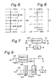
level comparators 26 to 28 are supplied to priority encoder 29. The two-bit code DT is obtained at theoutput terminal 8 of priority encoder 29. The encoder 29 generates a code of (1 1) in case (1), a code of (1 0) in case (2), a code of (0 1) in case (3), and a code of (0 0) in case (4). - As shown in Fig. 6, the picture element data PD of one block falls within the dynamic range DR from the minimum level MIN to the maximum level MAX. The
divider 23 divides the dynamic range DR into four equal parts.Comparators 26 to 28 determine to which of the 4 levels each data DTI belongs, and the result is converted to a two-bit code corresponding to the level range chosen. - Fig. 7 shows an example of another arrangement of the
encoder block 5. The dynamic range DR frominput terminal 21 is divided by 4 bydivider 31. An output signal ofdivider 31 is supplied as the denominator input to digital divider 30. The data DTI (after the removal of the minimum level) is supplied atinput terminal 22 as the numerator input to divider 30. The two-bit code DT is taken at the output of divider 30. The divider 30 generates a two-bit output corresponding to the value of the DT code. - Also, although not shown, the
encoder block 5 may be realized by a ROM to which total sixteen bits (the digital data DTI after the removal of the minimum level and the dynamic range DR) are supplied as an address. - In this embodiment, as is evident from Fig. 6, the dynamic range is divided into equal parts, and the central values L₀ L₁, L₂, and L₃ of each part is used as values upon decoding. This coding/decoding method helps reduce digitization distortion.
- However, the picture element data having the minimum level MIN and the maximum level MAX exist in each block. Therefore, as shown in Fig. 8, to increase the number of codes having no error, the dynamic range DR is divided into (2m - 1) equal parts (where m is the number of digitized bits). In this way, the minimum level MIN may be set to the representative level L₀ and the maximum level MAX may be set to the representative level L₃.
- Fig. 9 shows an arrangement of still another example of
encoder block 5. In Fig. 9, the data DTI (after the removal of the minimum level) is supplied to aninput terminal 161 and stored intoregister 162. An output ofregister 162 is supplied to an input terminal of abit selecting circuit 163. - The dynamic range DR from a
latch circuit 15 is supplied to aninput terminal 164. The dynamic range DR is supplied to apriority encoder 165. Thebit selecting circuit 163 is controlled by an output of three bits ofencoder 165. Among eight bits of the data DTI, four bits corresponding to the output of theencoder 165 are selected by thebit selecting circuit 163. - The output data of the
priority encoder 165 is taken out as a dynamic range data DR₂ which is transmitted to theoutput terminal 6. The four-bit output data of thebit selecting circuit 163 is taken at theoutput terminal 8 and transmitted as the code DT. - The
priority encoder 165 generates the three-bit output (C₂, C₁, C₀) in correspondence to the bit pattern of the high order four bits of the dynamic range DR. In response to the output of theencoder 165, thebit selecting circuit 163 selects four bits (Y₃, Y₂, Y₁, Y₀) from among eight bits (X₇, X₆, ..., X₀) of the data DTI (after the removal of the minimum level) and outputs this four-bit data as the code DT. - The relation between the output of the
priority encoder 165 corresponding to the high order four bits of the dynamic range DR and the output of four bits of thebit selecting circuit 163 which are selected by an output of thepriority encoder 165 is shown in the table below.
- The magnitude of the dynamic range DR is detected from the high order four bits and the minimum digitization unit is selected on the basis of the magnitude of the dynamic range DR. Three bits (C₂, C₁, C₀) indicative of the digitization unit are transmitted as the dynamic range informaiton DR₂.
- In Fig. 10, a
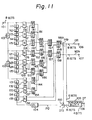
reference numeral 171 denotes four bits which are selected when the most significant bit MSB of the dynamic range DR is "1". In this case, the minimum digitization unit is 16.Numeral 172 denotes four bits which are selected when the MSB of the dynamic range DR is "0" and the second high order bit is "1". In this case, the minimum digitization unit is 8.Numeral 173 indicates four bits which are selected when the MSB and the second high order bit of the dynamic range DR are "0" and the third high order bit is "1". In this case, the minimum digitization unit is 4.Numeral 174 represents four bits which are selected when the MSB and the second and third high order bits of the dynamic range DR are "0" and the fourth high order bit is "1". In this case, the minimum digitization unit is 2.Numeral 175 indicates four bits which are selected when all of the high order four bits of the dynamic range are "0". In this case, the minimum digitization unit is 1. - Another embodiment of the invention, namely, an example whereby the invention is applied to picture elements of a two-dimensional block will now be explained with reference to the drawings. Fig. 11 shows the entire arrangement of an encoder for this embodiment. A digital video signal of the NTSC system in which, for example, one sample is digitized to eight bits, is inputted to an
input terminal 101. This digital video signal is supplied to a cascade connection ofline delay circuits - A cascade connection of five sample delay circuits 121 to 125 is connected to the connecting point of the
line delay circuits sample delay circuits 131 to 135 is connected to the output terminal ofline delay circuit 103. Due to theline delay circuits 102 and 103 (each having a delay amount of one line period) and the sample delay circuits 111 to 115, 121 to 125, and 131 to 135 (each having a delay amount equal to the sampling period of the input digital video signal), the picture element data of one block can be simultaneously obtained from output terminals of the respective delay circuits. - In Fig. 12, a
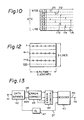
reference numeral 100 indicates one block, solid lines denote continuous n-th, (n+1)-th, and (n+2)-th lines of the current field, and broken lines represent lines of the other fields. One block consists of three lines. Each line contains six picture elements. When the picture element data of the (n+2)-th line is supplied to theinput terminal 101, the picture element data of the (n+1)-th line is generated at an output of theline delay circuit 102, and the picture element data of the n-th line is generated at an output of theline delay circuit 103. Six picture element data from each line are accessed at the input and output terminals of each cascade connection of the sample delay circuits, as well as between each of the delay circuits. - Two of the six picture element data of the same line (taken out by the cascade connection of the sample delay circuits 111 to 115) are supplied to each of the three selecting
circuits circuits circuits sample delay circuits 131 to 135. Each of these selecting circuits is a digital level comparator which is configured to compare the levels of two picture element data inputted, and output the picture element data of larger magnitude at one output terminal and output the picture element data of smaller magnitude at the other output terminal. - One output terminal of each of the selecting
circuits circuit 141. The other output terminals of the selectingcircuits circuit 151. One output terminal of each of the selectingcircuits circuit 142 and the other output terminals of the selectingcircuits circuit 152. One ouput terminal of each of the selectingcircuits circuit 143 and the other output terminals of the selectingcircuits circuit 153. One output terminal of each of the selectingcircuits circuit 144 and the other output terminals of the selectingcircuits circuit 154. - Each of the selecting
circuits 141 to 144 is a digital level comparator which is configured to compare the levels of two picture element data inputted and selectively output only the picture element data of larger magnitude. Each of the selectingcircuits 151 to 154 is a digital level comparator which is configured to compare the levels of two picture element data inputted and selectively output only the picture element data of smaller magnitude. - The outputs of the selecting
circuits circuits circuit 146. The outputs of the selectingcircuits 145 and 146 are supplied to a selectingcircuit 147. The output of the selectingcircuit 147 and the output of the larger level of the selectingcircuit 138 are supplied to a selectingcircuit 148. The selecting circuits 145 to 148 selectively output the picture element data of larger magnitude similar to the selectingcircuits 141 to 144. Therefore, the picture element data of the maximum level MAX among eighteen picture element data in theblock 100 is generated at an output terminal of the selectingcircuit 148. - The outputs of the selecting
circuits circuit 155. The outputs of the selectingcircuits circuit 156. The outputs of the selectingcircuits circuit 157. The output of the selectingcircuit 157 and the output of the smaller level of the selectingcircuit 138 are supplied to a selectingcircuit 158. The selectingcircuits 155 to 158 selectively output the picture element data of smaller magnitude, similar to the selectingcircuits 151 to 154. Therefore, the picture element data of the minimum level MIN among eighteen picture element data in theblock 100 is generated at an output terminal of the selectingcircuit 158. - The outputs of the selecting
circuits subtracter 149. Thesubtracter 149 subtracts the minimum level MIN from the maximum level MAX, so that the dynamic range DR of eight bits is obtained at anoutput terminal 106. The minimum level MIN is taken out at anoutput terminal 107 and supplied to asubtracter 150. - The picture element data PD generated at the output of the
sample delay circuit 135 is supplied to thesubtracter 150 through adelay circuit 104. Thedelay circuit 104 has a delay amount equal to the time lag which is caused by the detection of the maximum level MAX and minimum level MIN as mentioned above. The picture element data DTI of eight bits from which the minimum level was removed is obtained at the output of thesubtracter 150. - The dynamic range DR and the picture element data DTI (after the removal of the minimum level) are supplied to an
encoder block 105. Theencoder block 105 divides the dynamic range DR into equal parts according to the number of digitized bits (four bits in this example), and determines in which one of the divided areas the picture element data DTI (after the removal of the minimum level) is included, and generates the four-bit code DT to specify the decided area at anoutput terminal 108. The arrangement shown in Fig. 5, 7, or 9 may be used as a practical arrangement ofencoder block 5. - As described above, the dynamic range DR and minimum level MIN as additional data are obtained at the
output terminals output terminal 108. - One block of the original digital video signal consists of 144 bits (= 3 x 6 x 8 bits). According to this embodiment, one block consists of 88 bits (= 3 x 6 x 4 bits + 16 bits), so that the number of bits to be transmitted can be reduced by about one half.
- The code DT which is obtained at the
output terminal 108 of the encoder has the same sequence as the input video signal. Therefore, the additional data MIN and DR of each block are generated for every three lines with respect to the line, and for every six samples with regard to the sampling direction. When the transmission data is divided for every predetermined amount of the code DT, an interval including no additional data occurs in the transmission process. Therefore, a buffer memory is connected to the output of the encoder and the additional data DR and MIN and the code DT of one block may be used as a unit of transmission. In this case, the length of the data portion consisting of the coded code DT in Fig. 3 becomes 64 bits (= 4 bits x 16). - Fig. 13 shows an arrangement of the reception (or reproduction) side. Reception data from an
input terminal 41 is supplied to adata separating circuit 42, by which the DT code and additional codes are separated. The additional codes, namely, the minimum level MIN and dynamic range DR, are supplied to anerror correcting circuit 43 to correct any transmission error. Anerror concealing circuit 44 is connected to theerror correcting circuit 43. Theerror concealing circuit 44 conceals (interpolates) the additional codes which could not be corrected on the basis of an error flag from theerror correcting circuit 43. - The additional codes which are outputted from the
error concealing circuit 44 and the coded code DT, the timing of which was matched by adelay circuit 47, are supplied to adecoder 45. The code DT is decoded by thedecoder 45 and the original picture element data PD is taken out at anoutput terminal 46 of thedecoder 45. Thedecoder 45 decodes the eight-bit picture element data PD from the additional codes DR and MIN, each consisting of eight bits, and from the 4-bit DT code. - The
decoder 45 is configured as shown in Fig. 14. In Fig. 14, the code DT, dynamic range DR, and minimum level MIN frominput terminals latches latches 51 and 52. - The code DT from the latch 51 and the dynamic range DR from the
latch 52 are supplied to adecoder block 54. The data DTI (after the removal of the minimum level) is decoded by thedecoder block 54. The data DTI and the minimum level MIN from thelatch 53 are added by anadder 55, so that the picture element data PD is taken out at anoutput terminal 56 of theadder 55. Thedecoder block 54 decodes the representative value corresponding to the code DT. - Fig. 15 shows an arrangement of one example of the
decoder block 54. In the decoder block shown in Fig. 15 and a decoder block shown in Fig. 16 which will be mentioned later, it is assumed that the number of digitized bits of the DT code is two for simplicity of explanation. The decoder block of Fig. 15 has an arrangement corresponding to the encoder block shown in Fig. 5. - The dynamic range DR from an
input terminal 61 is divided by 4 by a divider 63 (which is comprised of a bit shifter to shift data by two bits) and the resultant data is supplied tomultipliers multiplier 64 triples the output of thedivider 63, andmultiplier 65 doubles the output of thedivider 63. The outputs of themultipliers divider 63, and the code in which eight bits are all "0" are supplied to aselector 66. Theselector 66 selects either one of four inputs in correspondence to the code DT from theinput terminal 62 and outputs. - When the code DT is (0 0), the
selector 66 selects the code of zero. When the coded code DT is (0 1), theselector 66 selects the output (
divider 63. When the DT is (1 0), theselector 66 selects the output (
multiplier 65. When the DT is (1 1), theselector 66 selects the output (
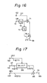
multiplier 64. The output of theselector 66 is supplied to anadder 68. The output of thedivider 63 is divided by 2 by a divider 67, and the resultant data is supplied to theadder 68. Therefore, the data DTI after the removal of the minimum level is obtained at anoutput terminal 69 of theadder 68. - Fig. 16 shows another example of the
decoder block 54. The example shown in Fig. 16 has an arrangement corresponding to the encoder block shown in Fig. 7. - In Fig. 16, a
digital multiplier 71 multiplies a value of (
input terminal 62. The multiplied output of themultiplier 71 and a data of (
divider 72 are supplied to anadder 73. The data DTI after the removal of the minimum level is taken out at theoutput terminal 69 of theadder 73. - Fig. 17 shows still another example of the
decoder block 54 and has an arrangement corresponding to the encoder block shown in Fig. 9. - In Fig. 17, the input data DT is supplied to an
input terminal 181 and the dynamic range information DR₂ inputted is supplied to aninput terminal 182. The minimum level MIN inputted is supplied to aninput terminal 183. The data DT is supplied to a selectingcircuit 184. The selectingcircuit 184 generates an output of eight bits selected on the basis of the dynamic range information DR₂ from among five kinds of eight-bit data in which "0" bits of total four bits were added to the high order side or low order side of the data DT of four bits. - The output data of the selecting
circuit 184 corresponds to the data DTI after the removal of the minimum level. The output of the selectingcircuit 184 is supplied to one input terminal of anudder 185. The minimum level MIN is supplied to the other input terminal of theadder 185. The picture element data PD is taken out at anoutput terminal 186 of theadder 185. - In the above description, three data of the code DT, dynamic range DR, and minimum level MIN are transmitted. However, as the additional codes, the minimum level MIN and maximum level MAX, or the dynamic range DR and minimum level MIN may be transmitted. Further, instead of transmitting the dynamic range DR, the minimum digitization level which is formed by this signal may be transmitted in place of this signal.
- According to the present invention, the amount of data to be transmitted can be reduced compared with the amount of original data. Thus, the transmission band can be narrowed. In addition, this invention has an advantage such that in the non-moving portion of the picture where the dynamic range of picture element data is small, the original picture element data can be completely recovered from the received data with little or no deterioration of picture quality. Moreover, according to the invention, since the dynamic range is evaluated separately for each block, the reconstructed pictured responds very well to motion in the moving part of the picture such as the edge where the dynamic range is large.
Claims (9)
- Coding apparatus for coding digital video data in the form of a block data to a compressed video data, comprising:first detecting means (10,12) for detecting a maximum value (MAX) of the digital video data of plural picture elements in said block,second detecting means (11,13) for detecting a minimum value (MIN) of the digital video data of plural picture elements in said block,means for generating (14) a dynamic range value (DR) of the data in the block by subtracting said minimum value (MIN) from said maximum value (MAX).means (16,4) for subtracting said minimum value (MIN) from each of the digital data to generate modified digital video data (DTI),means (5) for encoding said modified digital video data (DTI) using a fixed number of bits, which number is less than that of the original digital video data, so as to output compressed digital video data (DT),andtransmitting means for transmitting the output (DT) of said encoding means (5) and an additional code per block formed of at least two of said maximum value (MAX), said minimum value (MIN), and a signal representing said dynamic range value (DR).
- Apparatus according to claim 1, wherein said encoding means (8) includes a reference level signal generator (23-25) supplied with said dynamic range value (DR) for generating a number of reference levels representing different fractions of the dynamic range value (DR), comparator means (26,27,28) for comparing said modified digital video data (DTI) and said reference levels; and priority encoding means (29) supplied with the results of comparison by said comparator means (26-28) of the modified digital video data (DTI) with said fractions and for generating as the output of said encoding means a code representing said results and using said fixed number of bits.
- Apparatus according to claim 1, wherein said encoding means (8) includes level dividing means (31) supplied with said dynamic range value (DR) for level dividing said dynamic range (DR) by the number according to said fixed number, and a digital divider (30) for dividing said modified digital video data (DTI) by the output of said level dividing means (31), the output of said digital divider (30) being the output of said encoding means.
- Apparatus according to claim 1, wherein said encoding means (8) includes a priority encoding means (165) supplied with said dynamic range value (DR) and for generating an encoded data (DR2) with a smaller number of bits than that of said dynamic range value (DR), and a bit selector (163) supplied with said modified digital video data and for selecting a predetermined number of bits of said modified digital video data, said predetermined number being equal to said fixed number and said predetermined number being controlled by said encoded data (DR2).
- Apparatus according to claim 4, wherein said priority encoder (165) generates the encoded data representing the most significant bit position of said dynamic range value (DR) which contains a binary "1".
- Apparatus according to claim 1, wherein said transmitting means includes a parity adding circuit for adding parity data at least to said additional code.
- Apparatus according to claim 1, wherein said digital video data in each block represents a two dimensional group of picture elements.
- Apparatus according to claim 1, wherein said digital video data in each block represents a one dimensional group of picture elements.
- An apparatus for decoding a compressed video data signal transmitted by the transmitting means of a coding apparatus in accordance with claim 1, the apparatus comprising:input means (48,49,50) for receiving said compressed digital video data (DT), and said additional code (MAX, MIN, DR) per block;decoding means (54) responsive to said compressed digital video data (DT) and at least one of said additional codes (MAX, MIN, DR) for creating the said modified digital video data (DTI) as were by the said encoding means (5) of the coding apparatus in accordance with claim 1;adder means (55) for adding one of said additional data to said modified digital video data (DTI) to create picture element data (PD); andoutput means (56) for outputting said picture element data (PD).
Priority Applications (1)
| Application Number | Priority Date | Filing Date | Title |
|---|---|---|---|
| AT85309127T ATE62094T1 (en) | 1984-12-19 | 1985-12-16 | HIGH-PERFORMANCE TECHNOLOGY FOR ENCODING A DIGITAL VIDEO SIGNAL. |
Applications Claiming Priority (6)
| Application Number | Priority Date | Filing Date | Title |
|---|---|---|---|
| JP59266408A JP2785822B2 (en) | 1984-12-19 | 1984-12-19 | High-efficiency encoding device and decoding device for television signal |
| JP59266407A JPH0793723B2 (en) | 1984-12-19 | 1984-12-19 | High efficiency coding apparatus and coding method for television signal |
| JP266407/84 | 1984-12-19 | ||
| JP266408/84 | 1984-12-19 | ||
| JP59269868A JP2785823B2 (en) | 1984-12-21 | 1984-12-21 | High-efficiency television signal encoding apparatus and method, and decoding apparatus and method |
| JP269868/84 | 1984-12-21 |
Publications (3)
| Publication Number | Publication Date |
|---|---|
| EP0185533A2 EP0185533A2 (en) | 1986-06-25 |
| EP0185533A3 EP0185533A3 (en) | 1987-07-15 |
| EP0185533B1 true EP0185533B1 (en) | 1991-03-27 |
Family
ID=27335464
Family Applications (1)
| Application Number | Title | Priority Date | Filing Date |
|---|---|---|---|
| EP85309127A Expired EP0185533B1 (en) | 1984-12-19 | 1985-12-16 | High efficiency technique for coding a digital video signal |
Country Status (5)
| Country | Link |
|---|---|
| US (1) | US4703352A (en) |
| EP (1) | EP0185533B1 (en) |
| AU (1) | AU583078B2 (en) |
| CA (1) | CA1251555A (en) |
| DE (1) | DE3582314D1 (en) |
Families Citing this family (108)
| Publication number | Priority date | Publication date | Assignee | Title |
|---|---|---|---|---|
| AU579441B2 (en) * | 1985-01-16 | 1988-11-24 | Mitsubishi Denki Kabushiki Kaisha | Video encoding apparatus |
| JP2512894B2 (en) * | 1985-11-05 | 1996-07-03 | ソニー株式会社 | High efficiency coding / decoding device |
| JP2612557B2 (en) * | 1985-12-18 | 1997-05-21 | ソニー株式会社 | Data transmission receiving system and data decoding device |
| JP2540809B2 (en) * | 1986-07-30 | 1996-10-09 | ソニー株式会社 | High efficiency encoder |
| US4835599A (en) * | 1987-02-25 | 1989-05-30 | Digital Equipment Corporation | Apparatus and method for storing and transmitting images represented by logic signals |
| JP2508439B2 (en) * | 1987-05-29 | 1996-06-19 | ソニー株式会社 | High efficiency encoder |
| DE3853618T2 (en) * | 1987-11-27 | 1995-09-28 | Canon Kk | Device for transmitting image information. |
| US5070402A (en) * | 1987-11-27 | 1991-12-03 | Canon Kabushiki Kaisha | Encoding image information transmission apparatus |
| US4953019A (en) * | 1987-11-27 | 1990-08-28 | Canon Kabushiki Kaisha | Image signal encoding apparatus |
| US5040060A (en) * | 1987-12-01 | 1991-08-13 | Canon Kabushiki Kaisha | Image information transmission system with compression based on still-image redundancy |
| JP2629238B2 (en) * | 1988-02-05 | 1997-07-09 | ソニー株式会社 | Decoding device and decoding method |
| US4903124A (en) * | 1988-03-17 | 1990-02-20 | Canon Kabushiki Kaisha | Image information signal transmission apparatus |
| NL8801441A (en) * | 1988-06-06 | 1990-01-02 | Philips Nv | DEVICE FOR REPRODUCING DIGITALIZED VIDEO IMAGES. |
| NL8801440A (en) * | 1988-06-06 | 1990-01-02 | Philips Nv | DEVICE FOR REPRODUCING DIGITALIZED VIDEO IMAGES WITH SLOPE FLAT ERROR. |
| EP0432222A1 (en) * | 1988-08-23 | 1991-06-19 | Waldemar Dipl.-Ing. Kehler | Hierarchically range adaptive coding method for signals, especially suitable for picture analysis and codings |
| CA1326899C (en) * | 1988-10-14 | 1994-02-08 | Tetsujiro Kondo | Highly efficient coding apparatus |
| JP2900385B2 (en) * | 1988-12-16 | 1999-06-02 | ソニー株式会社 | Framing circuit and method |
| EP0398741B1 (en) * | 1989-05-19 | 1997-10-29 | Canon Kabushiki Kaisha | Image information transmitting system |
| JP2830111B2 (en) * | 1989-07-21 | 1998-12-02 | ソニー株式会社 | High efficiency coding device |
| US5193003A (en) * | 1989-08-15 | 1993-03-09 | Sony Corporation | Apparatus for decoding digital video data with small memory requirement |
| NL8902612A (en) * | 1989-10-23 | 1991-05-16 | Philips Nv | METHOD FOR TRANSMITTING A DIGITAL VIDEO SIGNAL AND RECEIVER FOR USE IN THE METHOD |
| US5166987A (en) * | 1990-04-04 | 1992-11-24 | Sony Corporation | Encoding apparatus with two stages of data compression |
| JPH0474063A (en) * | 1990-07-13 | 1992-03-09 | Matsushita Electric Ind Co Ltd | Coding method for picture |
| DE4028731A1 (en) * | 1990-09-10 | 1992-03-19 | Thomson Brandt Gmbh | DIGITAL TRANSMISSION AND / OR RECORDING SYSTEM FOR COMPONENT-ENCODED COLOR TELEVISION SIGNALS |
| JPH04185172A (en) * | 1990-11-20 | 1992-07-02 | Matsushita Electric Ind Co Ltd | High-efficiency coding device for digital image signal |
| JPH05122647A (en) * | 1991-10-30 | 1993-05-18 | Sony Corp | Digital video tape recorder |
| US5410616A (en) * | 1992-05-28 | 1995-04-25 | Unisys Corporation | Loop-up table image scaling for rational factors |
| JPH06125533A (en) * | 1992-10-13 | 1994-05-06 | Sony Corp | Error correction code additional device and error correcting device |
| KR940017695A (en) * | 1992-12-09 | 1994-07-27 | 정용문 | Halftone Image Coding Method Considering Similarity between Blocks |
| JP3259428B2 (en) * | 1993-03-24 | 2002-02-25 | ソニー株式会社 | Apparatus and method for concealing digital image signal |
| JP3271108B2 (en) * | 1993-12-03 | 2002-04-02 | ソニー株式会社 | Apparatus and method for processing digital image signal |
| US5734433A (en) * | 1995-06-21 | 1998-03-31 | Sony Corporation | Picture encoding apparatus, picture encoding method, picture encoding and transmitting method, and picture record medium |
| US6292591B1 (en) | 1996-07-17 | 2001-09-18 | Sony Coporation | Image coding and decoding using mapping coefficients corresponding to class information of pixel blocks |
| AU718453B2 (en) | 1996-07-17 | 2000-04-13 | Sony Corporation | Image coding and decoding using mapping coefficients corresponding to class information of pixel blocks |
| US6381369B1 (en) | 1996-07-17 | 2002-04-30 | Sony Corporation | Image coding apparatus, image coding method, image decoding method, image decoding apparatus, image data transmitting method and recording medium |
| AU714554B2 (en) | 1996-07-17 | 2000-01-06 | Sony Corporation | Image coding and decoding using mapping coefficients corresponding to class information of pixel blocks |
| TW359919B (en) | 1996-07-17 | 1999-06-01 | Sony Corp | Image coding apparatus, image coding method, image decoding method, image decoding apparatus, image data transmitting method and recording medium |
| US6282684B1 (en) | 1997-10-23 | 2001-08-28 | Sony Corporation | Apparatus and method for recovery of data in a lossy transmission environment |
| US6332042B1 (en) | 1997-10-23 | 2001-12-18 | Sony Corporation | Apparatus and method for encoding and decoding data in a lossy transmission environment |
| US6581170B1 (en) | 1997-10-23 | 2003-06-17 | Sony Corporation | Source coding to provide for robust error recovery during transmission losses |
| JP3915855B2 (en) | 1997-12-19 | 2007-05-16 | ソニー株式会社 | Image coding apparatus, image coding method, learning apparatus, and learning method |
| US6151416A (en) * | 1999-02-12 | 2000-11-21 | Sony Corporation | Method and apparatus for adaptive class tap selection according to multiple classification |
| US6154761A (en) * | 1999-02-12 | 2000-11-28 | Sony Corporation | Classified adaptive multiple processing system |
| US6591398B1 (en) | 1999-02-12 | 2003-07-08 | Sony Corporation | Multiple processing system |
| US6363118B1 (en) | 1999-02-12 | 2002-03-26 | Sony Corporation | Apparatus and method for the recovery of compression constants in the encoded domain |
| US6535148B1 (en) | 1999-02-12 | 2003-03-18 | Sony Corporation | Method and apparatus for truncated decoding |
| US6307979B1 (en) | 1999-02-12 | 2001-10-23 | Sony Corporation | Classified adaptive error recovery method and apparatus |
| US6178266B1 (en) | 1999-02-12 | 2001-01-23 | Sony Corporation | Method and apparatus for the recovery of compression constants in the encoded domain |
| US6519369B1 (en) | 1999-02-12 | 2003-02-11 | Sony Corporation | Method and apparatus for filter tap expansion |
| US6307560B1 (en) | 1999-02-12 | 2001-10-23 | Sony Corporation | Classified adaptive spatio-temporal format conversion method and apparatus |
| US6170074B1 (en) | 1999-02-12 | 2001-01-02 | Sony Corporation | Source coding to provide for robust error recovery |
| US6192161B1 (en) | 1999-02-12 | 2001-02-20 | Sony Corporation | Method and apparatus for adaptive filter tap selection according to a class |
| US6621936B1 (en) | 1999-02-12 | 2003-09-16 | Sony Corporation | Method and apparatus for spatial class reduction |
| US7010737B2 (en) * | 1999-02-12 | 2006-03-07 | Sony Corporation | Method and apparatus for error data recovery |
| US6697489B1 (en) | 1999-03-30 | 2004-02-24 | Sony Corporation | Method and apparatus for securing control words |
| US7730300B2 (en) | 1999-03-30 | 2010-06-01 | Sony Corporation | Method and apparatus for protecting the transfer of data |
| US7565546B2 (en) | 1999-03-30 | 2009-07-21 | Sony Corporation | System, method and apparatus for secure digital content transmission |
| US6549672B1 (en) | 1999-06-29 | 2003-04-15 | Sony Corporation | Method and apparatus for recovery of encoded data using central value |
| US6473876B1 (en) | 1999-06-29 | 2002-10-29 | Sony Corporation | Method and apparatus for encoding of bitstreams using rotation |
| US6389562B1 (en) | 1999-06-29 | 2002-05-14 | Sony Corporation | Source code shuffling to provide for robust error recovery |
| US6493842B1 (en) | 1999-06-29 | 2002-12-10 | Sony Corporation | Time-varying randomization for data synchronization and implicit information transmission |
| US6351494B1 (en) | 1999-09-24 | 2002-02-26 | Sony Corporation | Classified adaptive error recovery method and apparatus |
| US6522785B1 (en) | 1999-09-24 | 2003-02-18 | Sony Corporation | Classified adaptive error recovery method and apparatus |
| US6539517B1 (en) | 1999-11-09 | 2003-03-25 | Sony Corporation | Data transformation for explicit transmission of control information |
| US7039614B1 (en) | 1999-11-09 | 2006-05-02 | Sony Corporation | Method for simulcrypting scrambled data to a plurality of conditional access devices |
| US6754371B1 (en) | 1999-12-07 | 2004-06-22 | Sony Corporation | Method and apparatus for past and future motion classification |
| US7225164B1 (en) | 2000-02-15 | 2007-05-29 | Sony Corporation | Method and apparatus for implementing revocation in broadcast networks |
| US6687304B1 (en) * | 2000-04-19 | 2004-02-03 | Koninklijke Philips Electronics N.V. | Efficient video data data access using fixed ratio compression |
| US20030206631A1 (en) * | 2000-06-22 | 2003-11-06 | Candelore Brant L. | Method and apparatus for scrambling program data for furture viewing |
| US7350082B2 (en) | 2001-06-06 | 2008-03-25 | Sony Corporation | Upgrading of encryption |
| US7139398B2 (en) | 2001-06-06 | 2006-11-21 | Sony Corporation | Time division partial encryption |
| US7895616B2 (en) | 2001-06-06 | 2011-02-22 | Sony Corporation | Reconstitution of program streams split across multiple packet identifiers |
| US7747853B2 (en) | 2001-06-06 | 2010-06-29 | Sony Corporation | IP delivery of secure digital content |
| US7215770B2 (en) | 2002-01-02 | 2007-05-08 | Sony Corporation | System and method for partially encrypted multimedia stream |
| US7039938B2 (en) | 2002-01-02 | 2006-05-02 | Sony Corporation | Selective encryption for video on demand |
| US7292691B2 (en) | 2002-01-02 | 2007-11-06 | Sony Corporation | Progressive video refresh slice detection |
| US7242773B2 (en) | 2002-09-09 | 2007-07-10 | Sony Corporation | Multiple partial encryption using retuning |
| US7155012B2 (en) | 2002-01-02 | 2006-12-26 | Sony Corporation | Slice mask and moat pattern partial encryption |
| US7765567B2 (en) | 2002-01-02 | 2010-07-27 | Sony Corporation | Content replacement by PID mapping |
| US7302059B2 (en) | 2002-01-02 | 2007-11-27 | Sony Corporation | Star pattern partial encryption |
| US7233669B2 (en) | 2002-01-02 | 2007-06-19 | Sony Corporation | Selective encryption to enable multiple decryption keys |
| US7218738B2 (en) * | 2002-01-02 | 2007-05-15 | Sony Corporation | Encryption and content control in a digital broadcast system |
| US7376233B2 (en) | 2002-01-02 | 2008-05-20 | Sony Corporation | Video slice and active region based multiple partial encryption |
| US7823174B2 (en) | 2002-01-02 | 2010-10-26 | Sony Corporation | Macro-block based content replacement by PID mapping |
| US7530084B2 (en) | 2002-05-28 | 2009-05-05 | Sony Corporation | Method and apparatus for synchronizing dynamic graphics |
| WO2004012450A1 (en) * | 2002-07-30 | 2004-02-05 | Sony Corporation | Storage device, signal processor, and image signal processor, and their methods |
| US8818896B2 (en) | 2002-09-09 | 2014-08-26 | Sony Corporation | Selective encryption with coverage encryption |
| US7636481B2 (en) * | 2002-10-09 | 2009-12-22 | Sony Corporation | Image processing apparatus, method, storage medium, and program for compressing an input image using a motion vector that is detected based on stored position information of pixels |
| US7724907B2 (en) | 2002-11-05 | 2010-05-25 | Sony Corporation | Mechanism for protecting the transfer of digital content |
| US8572408B2 (en) | 2002-11-05 | 2013-10-29 | Sony Corporation | Digital rights management of a digital device |
| US8645988B2 (en) | 2002-12-13 | 2014-02-04 | Sony Corporation | Content personalization for digital content |
| US8667525B2 (en) | 2002-12-13 | 2014-03-04 | Sony Corporation | Targeted advertisement selection from a digital stream |
| US7409702B2 (en) | 2003-03-20 | 2008-08-05 | Sony Corporation | Auxiliary program association table |
| US7292692B2 (en) | 2003-03-25 | 2007-11-06 | Sony Corporation | Content scrambling with minimal impact on legacy devices |
| US7286667B1 (en) | 2003-09-15 | 2007-10-23 | Sony Corporation | Decryption system |
| US7263187B2 (en) | 2003-10-31 | 2007-08-28 | Sony Corporation | Batch mode session-based encryption of video on demand content |
| US7346163B2 (en) | 2003-10-31 | 2008-03-18 | Sony Corporation | Dynamic composition of pre-encrypted video on demand content |
| US7620180B2 (en) | 2003-11-03 | 2009-11-17 | Sony Corporation | Preparation of content for multiple conditional access methods in video on demand |
| US7343013B2 (en) | 2003-12-16 | 2008-03-11 | Sony Corporation | Composite session-based encryption of video on demand content |
| US7853980B2 (en) | 2003-10-31 | 2010-12-14 | Sony Corporation | Bi-directional indices for trick mode video-on-demand |
| KR20070083652A (en) * | 2004-09-13 | 2007-08-24 | 이엑스피웨이 | Method for compressing and decompressing a sequence of floating point numbers |
| US7895617B2 (en) | 2004-12-15 | 2011-02-22 | Sony Corporation | Content substitution editor |
| US8041190B2 (en) | 2004-12-15 | 2011-10-18 | Sony Corporation | System and method for the creation, synchronization and delivery of alternate content |
| US20070076971A1 (en) * | 2005-09-30 | 2007-04-05 | Nokia Corporation | Compression of images for computer graphics |
| US8185921B2 (en) | 2006-02-28 | 2012-05-22 | Sony Corporation | Parental control of displayed content using closed captioning |
| US7555464B2 (en) | 2006-03-01 | 2009-06-30 | Sony Corporation | Multiple DRM management |
| JP4835554B2 (en) * | 2007-09-06 | 2011-12-14 | ソニー株式会社 | Encoding apparatus and method, decoding apparatus and method, and program |
| JP5903597B2 (en) | 2011-07-13 | 2016-04-13 | パナソニックIpマネジメント株式会社 | Image compression apparatus, image expansion apparatus, and image processing apparatus |
Family Cites Families (6)
| Publication number | Priority date | Publication date | Assignee | Title |
|---|---|---|---|---|
| JPS57148430A (en) * | 1981-03-10 | 1982-09-13 | Victor Co Of Japan Ltd | Compression system and compression and expansion system for video composite signal |
| GB2103449B (en) * | 1981-06-29 | 1985-05-30 | Nippon Telegraph & Telephone | Method and apparatus for gray level signal processing |
| US4494144A (en) * | 1982-06-28 | 1985-01-15 | At&T Bell Laboratories | Reduced bandwidth video transmission |
| DE3317115A1 (en) * | 1983-05-10 | 1984-11-15 | Siemens AG, 1000 Berlin und 8000 München | METHOD FOR TRANSMITTING DIGITAL LUMINANCE AND CHROMINANCE SIGNALS FROM TELEVISION |
| DE3331426A1 (en) * | 1983-08-31 | 1985-03-14 | Siemens AG, 1000 Berlin und 8000 München | ARRANGEMENT FOR TWO-DIMENSIONAL DPCM CODING |
| DE3343404A1 (en) * | 1983-11-30 | 1985-06-05 | Siemens AG, 1000 Berlin und 8000 München | CIRCUIT ARRANGEMENT FOR FAST DETERMINATION OF THE LARGEST AMOUNT DIFFERENCE OF THREE BINARY NUMBER VALUES |
-
1985
- 1985-12-16 DE DE8585309127T patent/DE3582314D1/en not_active Expired - Lifetime
- 1985-12-16 CA CA000497763A patent/CA1251555A/en not_active Expired
- 1985-12-16 EP EP85309127A patent/EP0185533B1/en not_active Expired
- 1985-12-17 US US06/809,775 patent/US4703352A/en not_active Expired - Lifetime
- 1985-12-18 AU AU51404/85A patent/AU583078B2/en not_active Expired
Also Published As
| Publication number | Publication date |
|---|---|
| DE3582314D1 (en) | 1991-05-02 |
| AU583078B2 (en) | 1989-04-20 |
| EP0185533A3 (en) | 1987-07-15 |
| CA1251555A (en) | 1989-03-21 |
| US4703352A (en) | 1987-10-27 |
| AU5140485A (en) | 1986-06-26 |
| EP0185533A2 (en) | 1986-06-25 |
Similar Documents
| Publication | Publication Date | Title |
|---|---|---|
| EP0185533B1 (en) | High efficiency technique for coding a digital video signal | |
| EP0186444B1 (en) | Highly efficient coding apparatus for digital video signal | |
| EP0222592B1 (en) | High efficiency technique for coding a digital video signal | |
| US4866510A (en) | Digital video encoder | |
| EP0617558B1 (en) | Apparatus for concealing errors in data | |
| US5193003A (en) | Apparatus for decoding digital video data with small memory requirement | |
| US5010401A (en) | Picture coding and decoding apparatus using vector quantization | |
| US4953023A (en) | Coding apparatus for encoding and compressing video data | |
| USRE35093E (en) | Systems and methods for coding even fields of interlaced video sequences | |
| US5193004A (en) | Systems and methods for coding even fields of interlaced video sequences | |
| US4907081A (en) | Compression and coding device for video signals | |
| US4323916A (en) | Data rate reduction for digital video signals by subsampling and adaptive reconstruction | |
| US4340940A (en) | Hardware reduction by truncation of selected number of most significant bits for digital video system using subsampling and adaptive reconstruction | |
| EP1420585A1 (en) | Picture information converting apparatus and method thereof | |
| JPS61144989A (en) | High efficient coding device of television signal | |
| USRE35414E (en) | Picture coding and decoding apparatus using vector quantization | |
| US5036392A (en) | DATV encoding and decoding method and apparatus | |
| JPH088684B2 (en) | High efficiency code decoding device | |
| JP2604712B2 (en) | High-efficiency encoding / decoding device for television signal | |
| JP2785822B2 (en) | High-efficiency encoding device and decoding device for television signal | |
| JPH0797754B2 (en) | Encoding transmission device | |
| JP2785823B2 (en) | High-efficiency television signal encoding apparatus and method, and decoding apparatus and method | |
| JP2518215B2 (en) | High efficiency encoder | |
| JP2832972B2 (en) | Image data quantization circuit | |
| JPH02305280A (en) | Picture information transmission system |
Legal Events
| Date | Code | Title | Description |
|---|---|---|---|
| PUAI | Public reference made under article 153(3) epc to a published international application that has entered the european phase |
Free format text: ORIGINAL CODE: 0009012 |
|
| 17P | Request for examination filed |
Effective date: 19851220 |
|
| AK | Designated contracting states |
Kind code of ref document: A2 Designated state(s): AT DE FR GB NL |
|
| PUAL | Search report despatched |
Free format text: ORIGINAL CODE: 0009013 |
|
| AK | Designated contracting states |
Kind code of ref document: A3 Designated state(s): AT DE FR GB NL |
|
| 17Q | First examination report despatched |
Effective date: 19891106 |
|
| GRAA | (expected) grant |
Free format text: ORIGINAL CODE: 0009210 |
|
| AK | Designated contracting states |
Kind code of ref document: B1 Designated state(s): AT DE FR GB NL |
|
| REF | Corresponds to: |
Ref document number: 62094 Country of ref document: AT Date of ref document: 19910415 Kind code of ref document: T |
|
| REF | Corresponds to: |
Ref document number: 3582314 Country of ref document: DE Date of ref document: 19910502 |
|
| ET | Fr: translation filed | ||
| PLBE | No opposition filed within time limit |
Free format text: ORIGINAL CODE: 0009261 |
|
| STAA | Information on the status of an ep patent application or granted ep patent |
Free format text: STATUS: NO OPPOSITION FILED WITHIN TIME LIMIT |
|
| 26N | No opposition filed | ||
| REG | Reference to a national code |
Ref country code: GB Ref legal event code: IF02 |
|
| PGFP | Annual fee paid to national office [announced via postgrant information from national office to epo] |
Ref country code: NL Payment date: 20041205 Year of fee payment: 20 |
|
| PGFP | Annual fee paid to national office [announced via postgrant information from national office to epo] |
Ref country code: FR Payment date: 20041208 Year of fee payment: 20 |
|
| PGFP | Annual fee paid to national office [announced via postgrant information from national office to epo] |
Ref country code: DE Payment date: 20041209 Year of fee payment: 20 |
|
| PGFP | Annual fee paid to national office [announced via postgrant information from national office to epo] |
Ref country code: AT Payment date: 20041213 Year of fee payment: 20 |
|
| PGFP | Annual fee paid to national office [announced via postgrant information from national office to epo] |
Ref country code: GB Payment date: 20041215 Year of fee payment: 20 |
|
| PG25 | Lapsed in a contracting state [announced via postgrant information from national office to epo] |
Ref country code: GB Free format text: LAPSE BECAUSE OF EXPIRATION OF PROTECTION Effective date: 20051215 |
|
| PG25 | Lapsed in a contracting state [announced via postgrant information from national office to epo] |
Ref country code: NL Free format text: LAPSE BECAUSE OF EXPIRATION OF PROTECTION Effective date: 20051216 |
|
| REG | Reference to a national code |
Ref country code: GB Ref legal event code: PE20 |
|
| NLV7 | Nl: ceased due to reaching the maximum lifetime of a patent |
Effective date: 20051216 |