EP0184332A2 - Method and device for communicating information representing sound waves to the deaf - Google Patents
Method and device for communicating information representing sound waves to the deaf Download PDFInfo
- Publication number
- EP0184332A2 EP0184332A2 EP85308044A EP85308044A EP0184332A2 EP 0184332 A2 EP0184332 A2 EP 0184332A2 EP 85308044 A EP85308044 A EP 85308044A EP 85308044 A EP85308044 A EP 85308044A EP 0184332 A2 EP0184332 A2 EP 0184332A2
- Authority
- EP
- European Patent Office
- Prior art keywords
- nerve
- sound waves
- electrical impulses
- person
- applying
- Prior art date
- Legal status (The legal status is an assumption and is not a legal conclusion. Google has not performed a legal analysis and makes no representation as to the accuracy of the status listed.)
- Withdrawn
Links
Images

Classifications
-
- G—PHYSICS
- G09—EDUCATION; CRYPTOGRAPHY; DISPLAY; ADVERTISING; SEALS
- G09B—EDUCATIONAL OR DEMONSTRATION APPLIANCES; APPLIANCES FOR TEACHING, OR COMMUNICATING WITH, THE BLIND, DEAF OR MUTE; MODELS; PLANETARIA; GLOBES; MAPS; DIAGRAMS
- G09B21/00—Teaching, or communicating with, the blind, deaf or mute
- G09B21/009—Teaching or communicating with deaf persons
-
- A—HUMAN NECESSITIES
- A61—MEDICAL OR VETERINARY SCIENCE; HYGIENE
- A61F—FILTERS IMPLANTABLE INTO BLOOD VESSELS; PROSTHESES; DEVICES PROVIDING PATENCY TO, OR PREVENTING COLLAPSING OF, TUBULAR STRUCTURES OF THE BODY, e.g. STENTS; ORTHOPAEDIC, NURSING OR CONTRACEPTIVE DEVICES; FOMENTATION; TREATMENT OR PROTECTION OF EYES OR EARS; BANDAGES, DRESSINGS OR ABSORBENT PADS; FIRST-AID KITS
- A61F11/00—Methods or devices for treatment of the ears or hearing sense; Non-electric hearing aids; Methods or devices for enabling ear patients to achieve auditory perception through physiological senses other than hearing sense; Protective devices for the ears, carried on the body or in the hand
- A61F11/04—Methods or devices for enabling ear patients to achieve auditory perception through physiological senses other than hearing sense, e.g. through the touch sense
- A61F11/045—Methods or devices for enabling ear patients to achieve auditory perception through physiological senses other than hearing sense, e.g. through the touch sense using mechanical stimulation of nerves
Definitions
- the present invention relates to a method and apparatus for communicating information representative of air pressure sound waves to deaf persons, and more particularly to a method and apparatus for translating sound waves into electrical signals and stimulating certain nerves of the deaf person in accordance with such electrical signals.
- the prior art's efforts at providing some measure of hearing for the totally and partially deaf has been directed primarily at stimulating the inner ear or cochlea with signals derived from sound waves.
- the stimulated cochlea would in theory transmit signals to the brain through the auditory nerve, which could be translated into information representating the original sound waves.
- sound waves are translated into electrical impulses having characteristics representative of the sound waves.
- the electrical impulses are applied to the tactile sensory nerves originating in at least one hand of the deaf person.
- the electrical impulses may be applied directly to the nerves, e.g., by a pair of electrodes, and indirectly by means of a transducer which transforms the electrical impulses into mechanical vibrations.
- the apparatus of the present invention includes a sound wave transducer, e.g., a microphone having an output circuit and arranged for generating electrical impulses or signals in the output circuit having characteristics representative of the incident sound waves.
- Nerve-stimulating means having an input circuit are arranged to provide an output, preferably in the form of electrical impulses, across a pair of electrodes arranged to be placed in contact with the tactile sensory nerves.
- the apparatus further includes means for coupling the output signals from the sound wave transducer means to the input circuit of the nerve-stimulating means.
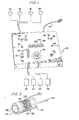
- a housing 10 encloses an audio-neural electrical circuit (shown in Figure 3) for receiving electrical signals from sound wave transducers or microphones 12, 14, 16 and 18, and translating such signals into appropriate output signals which are applied to finger stimulators 20, 22, 24 and 26 via a four-wire cable 28.
- an audio-neural electrical circuit shown in Figure 3 for receiving electrical signals from sound wave transducers or microphones 12, 14, 16 and 18, and translating such signals into appropriate output signals which are applied to finger stimulators 20, 22, 24 and 26 via a four-wire cable 28.
- the finger stimulators apply electrical impulses as well as vibrations characteristic of the sound waves to the deaf person's fingertips.
- This stimulation is transmitted to the brain via the tactile sensory nerves such as the radial nerve, which is illustrated in Figure 6.
- the human brain can, under certain circumstances, compensate for missing sensory input.
- a case in point is Helen Keller, who became proficient with the use of her tactile sense in developing oral responses. By feeling the vibrations in a normal person's throat, she was able to reproduce similar vibrations. Through the use of her tactile sense, she learned to speak with more than adequate articulation.
- I have discovered that totally deaf persons, after suitable training, can translate the signals imparted to their fingertips by the stimulators 20-26 of my invention into meaningful auditory information. For example, spoken words, as well as other sounds such as music, can be understood and/or appreciated.
- the cable 28 which applies the output signal from the audio-neural circuit to the finger stimulators 20-26 is coupled to the circuit by means of a jack 30 and connector 32.
- An auxiliary connector 33 is also provided for permitting audio signals from another source such as a tape, playback apparatus, etc., to be coupled to the circuit.
- a volume control knob 34 may be manually adjusted to provide an output signal of appropriate magnitude to the stimulators 20-26.
- a switch 36 is provided for connecting the circuit to a suitable source of power, i.e., a rechargeable battery.
- a pilot lamp or light-emitting diode 38 enables the operator to visually determine when the circuit is energized.
- Another switch 48 selectively connects the battery through a battery charger of conventional design to a source of a.c. power via cord 42.
- a light-emitting diode 44 visually informs the operator when the battery is being charged.
- Ten light-emitting diodes collectively designated by- numeral 46 provide a visual indication of the level of the output signal from the microphones 20-26, as will be discussed in connection with Figure 2.
- the microphones 12 and 14 are always connected to the audio-neural circuit.
- a switch 48 enables the operator to also connect microphones 16 and 18 to the circuit, as is illustrated in Figure 2.
- Light-emitting diodes 49, 50 are energized to indicate the use of only microphones 12 and 14 or all four microphones, respectively.
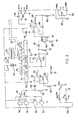
- one terminal of the microphones 12-18 is connected to the positive terminal of a battery 50 and the other terminal is connected to the positive input of an operational amplifier 52 through a capacitor 54.
- the microphones 16, 18 are coupled to the amplifier 52 through the ganged switch 48.
- the switch 48 includes one contact 48a for connecting the microphones 16, 18 to the input of the amplifier 52 and another contact 48b for connecting a light-emitting diode 49 between the positive terminal of the battery 50 and ground through a resistor 58, as illustrated.
- the diode 49 when energized indicates that microphones 16,11 are in the circuit.
- An additional light-emitting diode 51 is connected between the battery and ground through the resistor 58 to indicate that microphones 12, 14. are in the circuit.
- the operational amplifier 52 includes a negative input which is connected to ground through a resistor 60 in parallel with another resistor 62 and a capacitor 64, as shown.
- the junction of the capacitor 54 and the output of the microphones 12-18, is also connected to ground through a resistor 66.
- a feedback resistor 68 is connected between the output terminal 70 of the operational amplifier 52 and the negative input thereof.
- a selector switch 72 selectively connects the output terminal 70 of the amplifier 52 or the auxiliary input jack 33 to the positive input of a second operational amplifier 74 through a coupling capacitor 76, a resistor 78 and a level control potentiometer 80.
- the wiper 80a of the potentiometer 80 is controlled by knob 34.
- a resistor 81 is connected between a movable contact 72a of the switch 72 and ground.
- Resistor 82 is connected between the wiper 80a and ground to form a voltage divider network with the resistor 78.
- the negative input of the operational amplifier 74 is connected to the output terminal 84 through a feedback capacitor 86 and a resistor 88.
- the junction of the capacitor 86 and resistor 88 is connected to ground through a resistor 90.
- a power input terminal of the amplifier 74 is connected to the positive terminal of the battery 50 and a filter capacitor 92 is connected between the positive terminal of the battery and ground.
- a light-emitting diode bar driver 94 has an input coupled to the movable contact 72a of the switch 72 and output terminals connected to the ten light-emitting diodes 46. Power terminals 95 of the bar driver 94 are connected across the battery as shown.
- the bar driver 94 responds to the magnitude of the signal applied to the movable contact 72a of the switch 72 (i.e., the output from the amplifier 52 or the signal present on the auxiliary input jack 33) and energizes the diodes 46 serially as the magnitude is increased.
- the number of the diodes 46 which are energized provide an indication of the magnitude or level of the sound picked up by the microphones 12-1 8 or the level of the auxiliary input signal, depending upon the position of the switch 72.
- the output of the amplifier 74 is applied to one portion of the finger stimulators through a coupling capacitor 96 via terminals 97a and 97b and to another portion through transformer 98 via terminals 98a and 98b, as will become apparent in connection with the description of Figure 3.
- the transformer 98 includes a primary winding 100 connected between ground and the terminal 97a and a secondary winding 101 connected across, terminals 99a and 99b.
- Another filter capacitor 99 is connected between the output of the amplifier 74 and ground, as shown.
- Each finger stimulator includes two input circuits: One for providing electrical impulses characteristic of the sound waves received by the microphones 12-18 and another circuit for providing vibratory stimulation characteristic of the input to the microphones, as will become more apparent in reference to Figure 3.
- the electrical impulses across the electrodes modify the regeneration time of the pacinian and meisner nerve corpuscles, thereby permitting finite discrimination of the stimuli at high and low audio frequencies.
- the circuit of Figure 2 includes a conventional battery charger circuit 102 which is connected to a source of a.c. power (e.g., 120 volts, 60 Hz) through the cord 42 so that the battery can be periodically charged by operation of the switch 40.
- the light-emitting diode 44 connected in the output of the charger 102 is energized when the battery is being charged.
- the stimulator includes a plastic tube 104 on which is wound a transducer winding 106 which is connected to the terminals 97a and 97b via input circuit 110 and cable 28.
- a magnetic metal core 112 preferably made of ceramic (or plastic) with magnetic particles blended into the ceramic, extends within the tube 104 and is separated from tube 104 by a foam sleeve 114.
- the magnetic core 112 includes a tongue 113 which is adapted to receive one finger of the operator.
- a pair of electrodes 116 and 118 insulated from the core are mounted on this tongue 113 as illustrated, so that the electrodes will contact the surface of the finger at spaced points when the finger is inserted into the stimulator.
- Electrodes 116, 118 are connected by a pair of wires (also insulated from the core) . to an input circuit 120 which is turn is coupled to the output of the secondary winding 98b of the transformer 98 via cable 28.
- the deaf person inserts a thumb and three fingers of one hand into the finger stimulators 20, 22, 24, 26. If desired, only three finger stimulators need be used for the thumb and two fingers. Power is then applied from the battery 50 to the circuit via switch 36 and the volume control knob 34 is turned until sufficient stimulation is received from the stimulators 20-26 to enable the deaf person to discriminate between various sound waves picked up by the microphones (or audio signals from a tape recorder or the like if the auxiliary input is being used).
- deaf persons With training many deaf persons are able to associate the stimulation received from the stimulators 20-26 with the various sounds responsible for the stimulation. Through the use of my invention, deaf persons have been able to understand spoken words, identify the speaker by the characteristics of his or her voice, and gain some appreciation for other sounds such as music, etc.
- the system includes a transmitter portion 120 which receives sound waves via microphone 122 and transmits electromagnetic waves characteristic of the sound waves to a receiver portion 124 implanted in the user's wrist area.
- the microphone 122 is connected between the positive terminal of a suitable battery 123 (e.g., 3.0 volts) and ground.
- the output of the microphone 122 is applied to the negative input of an opera-. tional amplifier 126 through a coupling capacitor 128 and a variable resistor 130.
- the positive input of the amplifier 126 is connected to ground through a level control potentiometer 132.
- An adjustable feedback resistor 140 is connected between the output 142 and the negative input of the amplifier 126 to enable the gain of the amplifier to be adjusted.
- the output terminal 142 of the amplifier 126 is connected to a primary winding 144 of a transformer 146 through a capacitor 143.
- the receiver implant or nerve stimulator124 is encased in a suitable tissue-tolerant plastic material (not shown) and surgically implanted in the user's wrist area.
- the implant 124 includes a coil 148 which functions as the secondary of the transformer 144.
- the coil 148 converts the electromagnetic waves from the transmitter 120 into electrical impulses characteristic of the sound waves picked up by the microphone 122.
- the electrical impulses are applied across an output in the form of a pair of electrodes 150, 152 which are preferably inserted into one of the tactile sensory nerves originating in the hand.
- a voltage limiter 154 connected across the output electrodes serves to limit the voltage and/or current applied to the nerve to about 50-100 mv and 25-50 ma.
- the radial nerve branch has been chosen as the most convenient of the tactile sensory nerves for receiving electrical impulses from the electrodes 152, 153.
- the radial nerve is of a sufficient bundle size and is accessible surgically. This nerve ascends the arm to the brachial plexus where it converges with the ulner and median nerves to enter the spine through the fourth through the seventh vertebrae.
- Figure 5 generally illustrates the implant area and the portion of the radial nerve in that area. It should be noted that the ulnar or median nerves could be chosen to receive the electrodes. Each of these nerves traverse the wrist area.
- the receiver implant 124 requires no battery and thus does not have to be removed once in place.
- the user straps the transmitter 120 over his or her wrist so that the primary winding 144 of the transformer overlays the secondary winding 148.
- the resistors 130, 140 may then be adjusted to set the level of the input signal and the gain of the amplifier 126.
- the level control potentiometer 132 is readily accessible to the user to permit the magnitude of the stimulation received from the electrodes 152, 150 to be controlled with a given level of sound wave input.
- the system of Figure 4 requires training before the user can associate the stimulation of the radial nerve with the sounds producing the stimulation.
- Figure 6 illustrates a stereo system in which separate microphones 160, 162 are coupled to amplifiers 164, 166, respectively, with the output of such amplifiers applying output signals to the tactile sensory nerves of the right and left hands (or vice versa), respectively.
- the amplifiers 164, 166 may each comprise the circuits shown in Figures 2 or 4 with the corresponding nerve stimulators.
- an audio-neural communication system and method which is capable of providing stimulation (characteristic of incident sound waves) to the tactile sensory nerves originating in a deaf person's hands.
- the system is relatively inexpensive and surgery is optional.
Abstract
liquid dispenser (10) for dispensing a volumetric quantity of liquid (26) is disclosed. The dispenser (10) includes a plunger (11) having a longitudinal axis (30). First and second umbrella seals (14) and (15) are cooperatively connected to the plunger (11). The seals (14) and (15) are in spaced relationship. A plunger housing (16) encloses at least a portion of the plunger (11). The plunger housing (16) is adapted for relative movement with the plunger (11) along the longitudinal axis (30). The plunger housing (16) has an inner cavity (19a) having a first opening (19b) and a second opening (19c), wherein a measuring chamber is defined between the seals. Relative movement along the longitudinal axis (30) is effected between the plunger (11) and the plunger housing (16), wherein the plunger (11) moves from a filling to a dispensing position. When in the filling position, the second seal (15) seals the second opening 19(c) and the first seal (14) allows liquid (26) to enter the measuring chamber (19a) through the first opening (19b). When in the dispensing position, the first seal (14) seals the first opening (19b) and the second seal (15) allows liquid (26) to be dispensed by gravity from the second opening (19c). The first seal (14) always is in a sealing relationship to the first opening (19b) when the second seal (15) allows dispensing of the liquid (26), whereby a constant volume of liquid (26) is dispensed.
Description
- The present invention relates to a method and apparatus for communicating information representative of air pressure sound waves to deaf persons, and more particularly to a method and apparatus for translating sound waves into electrical signals and stimulating certain nerves of the deaf person in accordance with such electrical signals.
- The prior art's efforts at providing some measure of hearing for the totally and partially deaf has been directed primarily at stimulating the inner ear or cochlea with signals derived from sound waves. The stimulated cochlea would in theory transmit signals to the brain through the auditory nerve, which could be translated into information representating the original sound waves.
- One example of such prior art efforts is described in an article entitled "Success for the 'Bionic Ear' ", appearing in the March 12, 1984 issue of Time Magazine. According to this article, eight wires are implanted in the deaf person's inner ear and connected to an electrical plug extending through the skull. A microphone carried on the ear translates the sound waves into electrical signals which are then processed by a computer and applied to the implanted wires. Such prior art devices require delicate surgery, are expensive, and have not yet met with any great success.
- Another prior art effort is described in U.S. Patent No. 3,209,081 in which a hearing aid device in the form of a receiver implanted in the mastoid bone of the deaf person communicates with an external transmitter. The transmitter picks up sound waves through a microphone, translates the sound waves into audio signals, modulates a radio frequency (r.f.) signal with the audio signals and transmits the r.f. signal to the implanted receiver. The receiver then demodulates the received signal and applies the demodulated signals to the skull of the patient, where they are hopefully transmitted through the bone to the patient's inner ear.
- Although as described above the prior art has suggested several techniques for enabling the deaf to hear, such techniques have not gained any widespread acceptance.
- The reliability of the prior art methods have not been adequately proven. Furthermore, the nature of the surgery required to implant devices into the' skull has undoubtedly discouraged the widespread use of such methods. The method and apparatus of the present invention for communicating information representative of sound waves to the deaf overcomes the disadvantages of the prior art.
- In accordance with the method of the present invention, sound waves are translated into electrical impulses having characteristics representative of the sound waves. The electrical impulses are applied to the tactile sensory nerves originating in at least one hand of the deaf person. The electrical impulses may be applied directly to the nerves, e.g., by a pair of electrodes, and indirectly by means of a transducer which transforms the electrical impulses into mechanical vibrations.
- The apparatus of the present invention includes a sound wave transducer, e.g., a microphone having an output circuit and arranged for generating electrical impulses or signals in the output circuit having characteristics representative of the incident sound waves. Nerve-stimulating means having an input circuit are arranged to provide an output, preferably in the form of electrical impulses, across a pair of electrodes arranged to be placed in contact with the tactile sensory nerves. The apparatus further includes means for coupling the output signals from the sound wave transducer means to the input circuit of the nerve-stimulating means.
-
- Figure 1 is a perspective view of one preferred embodiment of the apparatus of the present invention;
- Figure 2 is a schematic circuit diagram of the electrical circuit employed in the apparatus of Figure 1;
- Figure 3 is an enlarged perspective view, partially broken away, of one of the finger stimulators used in the apparatus of Figure 1;
- Figure 4 is a schematic circuit diagram of a second preferred embodiment of the apparatus of the present invention in which an implant is employed to provide stimulation to the tactile sensory nerves;
- Figure 5 is a partial cross-sectional view of a human wrist and hand illustrating the location of the radial nerve and the area for receiving the implant of Figure 4; and
- Figure 6 is a block diagram of a circuit for providing stereo stimulation.
- The following specification taken in conjunction with the drawings sets forth the preferred embodiment of the present invention, although it should be understood that various modifications can be accomplished without departing from the spirit and scope of the invention.
- Referring now to Figure 1, a
housing 10 encloses an audio-neural electrical circuit (shown in Figure 3) for receiving electrical signals from sound wave transducers ormicrophones finger stimulators wire cable 28. - As will be explained, the finger stimulators apply electrical impulses as well as vibrations characteristic of the sound waves to the deaf person's fingertips. This stimulation is transmitted to the brain via the tactile sensory nerves such as the radial nerve, which is illustrated in Figure 6. It is well known that the human brain can, under certain circumstances, compensate for missing sensory input. A case in point is Helen Keller, who became proficient with the use of her tactile sense in developing oral responses. By feeling the vibrations in a normal person's throat, she was able to reproduce similar vibrations. Through the use of her tactile sense, she learned to speak with more than adequate articulation. Through extensive experimentation, I have discovered that totally deaf persons, after suitable training, can translate the signals imparted to their fingertips by the stimulators 20-26 of my invention into meaningful auditory information. For example, spoken words, as well as other sounds such as music, can be understood and/or appreciated.
- The
cable 28 which applies the output signal from the audio-neural circuit to the finger stimulators 20-26 is coupled to the circuit by means of ajack 30 andconnector 32. Anauxiliary connector 33 is also provided for permitting audio signals from another source such as a tape, playback apparatus, etc., to be coupled to the circuit. Avolume control knob 34 may be manually adjusted to provide an output signal of appropriate magnitude to the stimulators 20-26. Aswitch 36 is provided for connecting the circuit to a suitable source of power, i.e., a rechargeable battery. A pilot lamp or light-emitting diode 38 enables the operator to visually determine when the circuit is energized. Anotherswitch 48 selectively connects the battery through a battery charger of conventional design to a source of a.c. power viacord 42. A light-emitting diode 44 visually informs the operator when the battery is being charged. - Ten light-emitting diodes collectively designated by-
numeral 46 provide a visual indication of the level of the output signal from the microphones 20-26, as will be discussed in connection with Figure 2. Themicrophones switch 48 enables the operator to also connectmicrophones emitting diodes microphones - Referring now to Figure 2, one terminal of the microphones 12-18 is connected to the positive terminal of a
battery 50 and the other terminal is connected to the positive input of anoperational amplifier 52 through acapacitor 54. As is illustrated, themicrophones amplifier 52 through the gangedswitch 48. Theswitch 48 includes onecontact 48a for connecting themicrophones amplifier 52 and anothercontact 48b for connecting a light-emitting diode 49 between the positive terminal of thebattery 50 and ground through aresistor 58, as illustrated. Thediode 49 when energized indicates thatmicrophones emitting diode 51 is connected between the battery and ground through theresistor 58 to indicate thatmicrophones switch 48 in the position illustrated, themicrophones amplifier 52 along with themicrophones - The
operational amplifier 52 includes a negative input which is connected to ground through aresistor 60 in parallel withanother resistor 62 and acapacitor 64, as shown. The junction of thecapacitor 54 and the output of the microphones 12-18, is also connected to ground through aresistor 66. Afeedback resistor 68 is connected between theoutput terminal 70 of theoperational amplifier 52 and the negative input thereof. - A
selector switch 72 selectively connects theoutput terminal 70 of theamplifier 52 or theauxiliary input jack 33 to the positive input of a secondoperational amplifier 74 through acoupling capacitor 76, aresistor 78 and a level control potentiometer 80. The wiper 80a of the potentiometer 80 is controlled byknob 34. Aresistor 81 is connected between a movable contact 72a of theswitch 72 and ground. Resistor 82 is connected between the wiper 80a and ground to form a voltage divider network with theresistor 78. The negative input of theoperational amplifier 74 is connected to theoutput terminal 84 through afeedback capacitor 86 and aresistor 88. The junction of thecapacitor 86 andresistor 88 is connected to ground through aresistor 90. A power input terminal of theamplifier 74 is connected to the positive terminal of thebattery 50 and afilter capacitor 92 is connected between the positive terminal of the battery and ground. - A light-emitting
diode bar driver 94 has an input coupled to the movable contact 72a of theswitch 72 and output terminals connected to the ten light-emittingdiodes 46.Power terminals 95 of thebar driver 94 are connected across the battery as shown. Thebar driver 94 responds to the magnitude of the signal applied to the movable contact 72a of the switch 72 (i.e., the output from theamplifier 52 or the signal present on the auxiliary input jack 33) and energizes thediodes 46 serially as the magnitude is increased. Thus the number of thediodes 46 which are energized provide an indication of the magnitude or level of the sound picked up by the microphones 12-18 or the level of the auxiliary input signal, depending upon the position of theswitch 72. - The output of the
amplifier 74 is applied to one portion of the finger stimulators through acoupling capacitor 96 viaterminals transformer 98 viaterminals transformer 98 includes a primary winding 100 connected between ground and the terminal 97a and a secondary winding 101 connected across, terminals 99a and 99b. Anotherfilter capacitor 99 is connected between the output of theamplifier 74 and ground, as shown. - Each finger stimulator includes two input circuits: One for providing electrical impulses characteristic of the sound waves received by the microphones 12-18 and another circuit for providing vibratory stimulation characteristic of the input to the microphones, as will become more apparent in reference to Figure 3. The electrical impulses across the electrodes modify the regeneration time of the pacinian and meisner nerve corpuscles, thereby permitting finite discrimination of the stimuli at high and low audio frequencies. The circuit of Figure 2 includes a conventional
battery charger circuit 102 which is connected to a source of a.c. power (e.g., 120 volts, 60 Hz) through thecord 42 so that the battery can be periodically charged by operation of theswitch 40. The light-emittingdiode 44 connected in the output of thecharger 102 is energized when the battery is being charged. - Referring now to Figure 3, there is illustrated one of the finger stimulators 20-26. The stimulator includes a plastic tube 104 on which is wound a transducer winding 106 which is connected to the
terminals input circuit 110 andcable 28. A magnetic metal core 112, preferably made of ceramic (or plastic) with magnetic particles blended into the ceramic, extends within the tube 104 and is separated from tube 104 by afoam sleeve 114. The magnetic core 112 includes atongue 113 which is adapted to receive one finger of the operator. A pair ofelectrodes tongue 113 as illustrated, so that the electrodes will contact the surface of the finger at spaced points when the finger is inserted into the stimulator.Electrodes input circuit 120 which is turn is coupled to the output of the secondary winding 98b of thetransformer 98 viacable 28. - In operation, the deaf person inserts a thumb and three fingers of one hand into the
finger stimulators battery 50 to the circuit viaswitch 36 and thevolume control knob 34 is turned until sufficient stimulation is received from the stimulators 20-26 to enable the deaf person to discriminate between various sound waves picked up by the microphones (or audio signals from a tape recorder or the like if the auxiliary input is being used). - With training many deaf persons are able to associate the stimulation received from the stimulators 20-26 with the various sounds responsible for the stimulation. Through the use of my invention, deaf persons have been able to understand spoken words, identify the speaker by the characteristics of his or her voice, and gain some appreciation for other sounds such as music, etc.
- The following is a table of the component values used in the circuit of Figure 2.


- The component values provided in the above table are exemplary only.
- Referring now to Figure 4, there is illustrated an audio-neural communication system which may be worn by the user. The system includes a
transmitter portion 120 which receives sound waves viamicrophone 122 and transmits electromagnetic waves characteristic of the sound waves to areceiver portion 124 implanted in the user's wrist area. Themicrophone 122 is connected between the positive terminal of a suitable battery 123 (e.g., 3.0 volts) and ground. The output of themicrophone 122 is applied to the negative input of an opera-.tional amplifier 126 through acoupling capacitor 128 and avariable resistor 130. The positive input of theamplifier 126 is connected to ground through alevel control potentiometer 132. Anadjustable feedback resistor 140 is connected between theoutput 142 and the negative input of theamplifier 126 to enable the gain of the amplifier to be adjusted. Theoutput terminal 142 of theamplifier 126 is connected to a primary winding 144 of a transformer 146 through acapacitor 143. - The receiver implant or nerve stimulator124 is encased in a suitable tissue-tolerant plastic material (not shown) and surgically implanted in the user's wrist area. The
implant 124 includes acoil 148 which functions as the secondary of thetransformer 144. Thecoil 148 converts the electromagnetic waves from thetransmitter 120 into electrical impulses characteristic of the sound waves picked up by themicrophone 122. The electrical impulses are applied across an output in the form of a pair ofelectrodes voltage limiter 154 connected across the output electrodes serves to limit the voltage and/or current applied to the nerve to about 50-100 mv and 25-50 ma. - The radial nerve branch has been chosen as the most convenient of the tactile sensory nerves for receiving electrical impulses from the
electrodes 152, 153. The radial nerve is of a sufficient bundle size and is accessible surgically. This nerve ascends the arm to the brachial plexus where it converges with the ulner and median nerves to enter the spine through the fourth through the seventh vertebrae. Figure 5 generally illustrates the implant area and the portion of the radial nerve in that area. It should be noted that the ulnar or median nerves could be chosen to receive the electrodes. Each of these nerves traverse the wrist area. - The
receiver implant 124 requires no battery and thus does not have to be removed once in place. In operation the user straps thetransmitter 120 over his or her wrist so that the primary winding 144 of the transformer overlays the secondary winding 148. Theresistors amplifier 126. Thelevel control potentiometer 132 is readily accessible to the user to permit the magnitude of the stimulation received from theelectrodes - Figure 6 illustrates a stereo system in which
separate microphones amplifiers amplifiers - There has thus been described an audio-neural communication system and method which is capable of providing stimulation (characteristic of incident sound waves) to the tactile sensory nerves originating in a deaf person's hands. The system is relatively inexpensive and surgery is optional.
- The method and system is uncomplicated and effective. It will be apparent to those skilled in the art that various modifications are possible without departing from the scope and spirit of the present invention.
Claims (16)
1. A method of communicating information representative of sound waves to a deaf person comprising the steps of:
a) translating the sound waves into electrical impulses and mechanical vibrations having characteristics representative of the sound waves;
b) applying the electrical impulses to tactile sensory nerves of the person; and
c) applying the mechanical vibrations to the same tactile sensory nerves whereby the electrical impulses enable the nerves to respond to vibrations having the frequency components contained in normal speech.
2. The method of Claim 1 wherein the tactile sensory nerves originate in the hand of the person.
3. The method of Claim 1 wherein the step of applying the electrical impulses comprises applying the electrical impulses across two spaced-apart electrodes in contact with the person's pacinian or meisner nerve corpuscles.
4. The method of Claim 3 wherein the step of applying the mechanical vibrations comprises applying the mechanical vibrations directly to said pacinian or meisner nerve corpuscles whereby the electrical impulses modify the regeneration time of said corpuscles to allow the corpuscles to discriminate between the high and low frequency vibrations characterstic of normal speech.
5. The method of Claim 3 wherein the applying step comprises applying the electrical impulses across two spaced-apart electrodes in contact with at least one finger of one hand of the person.
6. The method of Claim 4 wherein the tactile sensory nerve is a portion of the radial nerve.
7. A method of communicating information having characteristics of air pressure sound waves to a deaf person, comprising the steps of:
a) implanting a nerve stimulator into a wrist area of the person, the nerve-stimulator having a coil for receiving electromagnetic waves having frequencies within the audio range and a pair of electrodes connected to the coil, the implanting step including the step of placing the electrodes directly into one of the tactile sensory nerves originating in the hand;
b) translating the sound waves into electrical signals;
c) generating electromagnetic waves in response to said electrical signals; and
d) applying the electromagnetic waves to a coil of the nerve stimulator, whereby electrical impulses characteristic of the sound waves are applied to said nerve.
8. The method of Claim 7 including the additional step of limiting the magnitude of the electrical impulses applied to the nerve.
9. The method of Claim 7 wherein said tactile sensory nerve is the radial nerve.
10. The method of Claim 7 wherein said tactile sensory nerve is the ulnar nerve.
11. The method of Claim 7 wherein said tactile sensory nerve is the median nerve.
12. The method of communicating information representative of air pressure sound waves to a deaf person, comprising the steps of:
a) translating the sound waves into electrical impulses;
b) amplifying the electrical impulses; and
c) applying the electrical impulses to the tips of a plurality of the deaf person's fingers.
13. The method of Claim 12 including the additional steps of transforming the amplified electrical signals into mechanical vibrations and applying the vibrations to said plurality of fingers.
14. In an audio-neural communications system for stimulation of the tactile sensory nerves of a deaf person having a sound transducer responsive to air pressure sound waves for generating electrical signals having characteristics representative of the sound waves and a nerve-stimulator having an input connected to receive the electrical signals from the sound transducer, the nerve stimulator characterized by:
at least one vibration transducer adapted to impart vibrations to nerve endings located within an area of the skin of the person when pressed thereagainst; and
at least one pair of spaced electrodes adapted to contact the skin within said area for transmitting electrical impulses to the nerve endings, the vibrations and electrical impulses being characteristic of the electrical signals produced by the sound transducers.
15. The audio-neural communications system of Claim 14 wherein the nerve stimulator is adapted to contact a finger of the deaf person to impart electrical impulses and vibrations thereto which are characteristic of the signals generated by the sound transducer.
16. In an audio-neural communications system for stimulation of the tactile sensory nerve of a deaf person having a sound transducer responsive to air pressure sound waves for generating electrical signals representative of the sound waves and a nerve stimulator having an input connected to receive the electrical signals from the sound transducer, the nerve stimulator characterized by:
a coil for receiving electromagnetric waves having frequencies within the audio range and a pair of electrodes connected to the coils so that magnetic flux changes within the coil will produce a voltage across the electrodes representative of the flux changes within the coil;
the coil and electrodes being adapted for implantation into the person's wrist so that the electrodes contact one of the tactile sensory nerves originating in the hand; and
a transmitter adapted to be worn on the person's wrist adjacent the implanted coil for changing the magnetic flux within the implanted coil in accordance with the electrical signals from the sound transducer so that electrical impulses characteristic of the received sound waves are imparted to the tacticle sensory nerve.
Applications Claiming Priority (2)
| Application Number | Priority Date | Filing Date | Title |
|---|---|---|---|
| US66924084A | 1984-11-07 | 1984-11-07 | |
| US669240 | 2000-09-25 |
Publications (2)
| Publication Number | Publication Date |
|---|---|
| EP0184332A2 true EP0184332A2 (en) | 1986-06-11 |
| EP0184332A3 EP0184332A3 (en) | 1988-07-06 |
Family
ID=24685625
Family Applications (1)
| Application Number | Title | Priority Date | Filing Date |
|---|---|---|---|
| EP85308044A Withdrawn EP0184332A3 (en) | 1984-11-07 | 1985-11-05 | Method and device for communicating information representing sound waves to the deaf |
Country Status (7)
| Country | Link |
|---|---|
| US (1) | US4813419A (en) |
| EP (1) | EP0184332A3 (en) |
| JP (1) | JPS61159967A (en) |
| KR (1) | KR860003822A (en) |
| AU (1) | AU4933285A (en) |
| ES (1) | ES8801760A1 (en) |
| IL (1) | IL76865A0 (en) |
Cited By (2)
| Publication number | Priority date | Publication date | Assignee | Title |
|---|---|---|---|---|
| FR2800966A1 (en) * | 1999-11-10 | 2001-05-11 | Jean Max Coudon | TOUCH STIMULATION DEVICE FOR USE BY A DEAF PERSON |
| WO2001038958A1 (en) * | 1999-11-24 | 2001-05-31 | Center For Advanced Science And Technology Incubation, Ltd. | Method and device for stimulating tactile sensation by electricity |
Families Citing this family (22)
| Publication number | Priority date | Publication date | Assignee | Title |
|---|---|---|---|---|
| US5035242A (en) * | 1990-04-16 | 1991-07-30 | David Franklin | Method and apparatus for sound responsive tactile stimulation of deaf individuals |
| EP0775323B1 (en) * | 1994-08-05 | 1999-06-16 | Apollon's Algebra (Gibraltar) Limited | Tactile-acoustic information detecting and measuring apparatus and method |
| US5860935A (en) * | 1996-10-29 | 1999-01-19 | Novid Inc. | Game apparatus and method for monitoring psycho-physiological responses to questions |
| FR2798475B1 (en) * | 1999-09-14 | 2001-10-19 | Christophe Cayrol | DEVICE FOR ADVISING A PERSON MOVING ON A GIVEN PATH, OF THE PRESENCE, ON THIS PATH, OF OBJECTS POSSIBLY POSING A DANGER FOR THEM |
| US20030236456A1 (en) * | 2001-04-20 | 2003-12-25 | Graham Simon J. | Vibrotactile devices for controlled somatosensory stimulus during functional magnetic resonance imaging |
| US7251605B2 (en) * | 2002-08-19 | 2007-07-31 | The United States Of America As Represented By The Secretary Of The Navy | Speech to touch translator assembly and method |
| US20110071439A1 (en) * | 2003-10-22 | 2011-03-24 | Wicab, Inc. | Tactile input system |
| US10589087B2 (en) | 2003-11-26 | 2020-03-17 | Wicab, Inc. | Systems and methods for altering brain and body functions and for treating conditions and diseases of the same |
| CA2648286A1 (en) * | 2003-11-26 | 2005-06-09 | Wicab, Inc. | Systems and methods for altering vestibular biology |
| US20060241718A1 (en) * | 2003-11-26 | 2006-10-26 | Wicab, Inc. | Systems and methods for altering brain and body functions and for treating conditions and diseases of the same |
| US20090312817A1 (en) * | 2003-11-26 | 2009-12-17 | Wicab, Inc. | Systems and methods for altering brain and body functions and for treating conditions and diseases of the same |
| US20090306741A1 (en) * | 2006-10-26 | 2009-12-10 | Wicab, Inc. | Systems and methods for altering brain and body functions and for treating conditions and diseases of the same |
| KR100873787B1 (en) | 2007-01-05 | 2008-12-15 | 광주과학기술원 | Message Delivery Device and Message Delivery Method |
| US20090138270A1 (en) * | 2007-11-26 | 2009-05-28 | Samuel G. Fletcher | Providing speech therapy by quantifying pronunciation accuracy of speech signals |
| GB2458533B (en) * | 2008-03-27 | 2012-10-03 | Roy Collison | Voice translation device for use on hand or body for blind deaf persons as a replacement for the human ear |
| US20110046687A1 (en) * | 2009-08-14 | 2011-02-24 | Raimund Naschberger | Live combined stimulation of auditory, sensory and motor functions and enhanced therapeutic and communicative applications based on advanced generation of complex electrical signals |
| US8888720B2 (en) * | 2010-04-02 | 2014-11-18 | Stanford P. Hudson | Great toe dorsiflexion detection |
| US20120250881A1 (en) * | 2011-03-29 | 2012-10-04 | Mulligan Daniel P | Microphone biasing |
| KR101395897B1 (en) * | 2011-11-04 | 2014-05-15 | 문찬곤 | Low frequency electric stimulator using music and diet system having the low frequency electric stimulator |
| WO2015033152A2 (en) * | 2013-09-04 | 2015-03-12 | Zero360, Inc. | Wearable device |
| US10475354B2 (en) | 2017-04-17 | 2019-11-12 | Facebook, Inc. | Haptic communication using dominant frequencies in speech signal |
| US10375930B1 (en) | 2017-07-07 | 2019-08-13 | Chad R. James | Animal training device that controls stimulus using proportional pressure-based input |
Citations (4)
| Publication number | Priority date | Publication date | Assignee | Title |
|---|---|---|---|---|
| US2995633A (en) * | 1958-09-25 | 1961-08-08 | Henry K Puharich | Means for aiding hearing |
| US3156787A (en) * | 1962-10-23 | 1964-11-10 | Henry K Puharich | Solid state hearing system |
| US3170993A (en) * | 1962-01-08 | 1965-02-23 | Henry K Puharich | Means for aiding hearing by electrical stimulation of the facial nerve system |
| DE3003315A1 (en) * | 1980-01-30 | 1981-08-06 | Siemens AG, 1000 Berlin und 8000 München | METHOD FOR GENERATING ELECTROCUTANE IRRITATING PATTERNS AS A CARRIER OF ACOUSTIC INFORMATION AND DEVICE FOR IMPLEMENTING THIS METHOD |
Family Cites Families (13)
| Publication number | Priority date | Publication date | Assignee | Title |
|---|---|---|---|---|
| US1652283A (en) * | 1927-04-04 | 1927-12-13 | Jay H Lewis | Protector for bit points |
| US2150364A (en) * | 1937-07-31 | 1939-03-14 | Bell Telephone Labor Inc | Signaling system |
| US2233848A (en) * | 1938-06-30 | 1941-03-04 | Bell Telephone Labor Inc | Audiphone |
| US2582277A (en) * | 1946-02-12 | 1952-01-15 | Neil C Powlison | Person alerting device |
| US3509289A (en) * | 1967-10-26 | 1970-04-28 | Zenith Radio Corp | Binaural hearing aid system |
| US3766331A (en) * | 1971-11-24 | 1973-10-16 | Zcm Ltd | Hearing aid for producing sensations in the brain |
| US3954101A (en) * | 1973-03-02 | 1976-05-04 | Wachspress How F | Audiotactile communication system |
| JPS52131677A (en) * | 1976-04-26 | 1977-11-04 | Kogyo Gijutsuin | Information transmitting device by electric stimulation |
| US4139742A (en) * | 1977-02-02 | 1979-02-13 | Walker Jay F | Cutaneous communication device |
| US4237448A (en) * | 1979-04-30 | 1980-12-02 | Motorola, Inc. | Pager with escalating audio alert signal level |
| US4340063A (en) * | 1980-01-02 | 1982-07-20 | Empi, Inc. | Stimulation device |
| CA1189147A (en) * | 1980-12-12 | 1985-06-18 | James F. Patrick | Speech processors |
| US4581491A (en) * | 1984-05-04 | 1986-04-08 | Research Corporation | Wearable tactile sensory aid providing information on voice pitch and intonation patterns |
-
1985
- 1985-10-28 IL IL76865A patent/IL76865A0/en unknown
- 1985-11-04 AU AU49332/85A patent/AU4933285A/en not_active Abandoned
- 1985-11-05 EP EP85308044A patent/EP0184332A3/en not_active Withdrawn
- 1985-11-06 KR KR1019850008274A patent/KR860003822A/en not_active Application Discontinuation
- 1985-11-06 ES ES548574A patent/ES8801760A1/en not_active Expired
- 1985-11-07 JP JP60250609A patent/JPS61159967A/en active Pending
-
1988
- 1988-03-22 US US07/172,945 patent/US4813419A/en not_active Expired - Fee Related
Patent Citations (4)
| Publication number | Priority date | Publication date | Assignee | Title |
|---|---|---|---|---|
| US2995633A (en) * | 1958-09-25 | 1961-08-08 | Henry K Puharich | Means for aiding hearing |
| US3170993A (en) * | 1962-01-08 | 1965-02-23 | Henry K Puharich | Means for aiding hearing by electrical stimulation of the facial nerve system |
| US3156787A (en) * | 1962-10-23 | 1964-11-10 | Henry K Puharich | Solid state hearing system |
| DE3003315A1 (en) * | 1980-01-30 | 1981-08-06 | Siemens AG, 1000 Berlin und 8000 München | METHOD FOR GENERATING ELECTROCUTANE IRRITATING PATTERNS AS A CARRIER OF ACOUSTIC INFORMATION AND DEVICE FOR IMPLEMENTING THIS METHOD |
Cited By (4)
| Publication number | Priority date | Publication date | Assignee | Title |
|---|---|---|---|---|
| FR2800966A1 (en) * | 1999-11-10 | 2001-05-11 | Jean Max Coudon | TOUCH STIMULATION DEVICE FOR USE BY A DEAF PERSON |
| EP1100286A1 (en) * | 1999-11-10 | 2001-05-16 | Jean-Max Coudon | Tactile stimulation device for deaf |
| US6628195B1 (en) | 1999-11-10 | 2003-09-30 | Jean-Max Coudon | Tactile stimulation device for use by a deaf person |
| WO2001038958A1 (en) * | 1999-11-24 | 2001-05-31 | Center For Advanced Science And Technology Incubation, Ltd. | Method and device for stimulating tactile sensation by electricity |
Also Published As
| Publication number | Publication date |
|---|---|
| ES548574A0 (en) | 1988-02-16 |
| JPS61159967A (en) | 1986-07-19 |
| ES8801760A1 (en) | 1988-02-16 |
| KR860003822A (en) | 1986-06-13 |
| EP0184332A3 (en) | 1988-07-06 |
| US4813419A (en) | 1989-03-21 |
| IL76865A0 (en) | 1986-02-28 |
| AU4933285A (en) | 1986-05-15 |
Similar Documents
| Publication | Publication Date | Title |
|---|---|---|
| EP0184332A2 (en) | Method and device for communicating information representing sound waves to the deaf | |
| US4063048A (en) | Implantable electronic hearing aid | |
| US4207441A (en) | Auditory prosthesis equipment | |
| CA2720560C (en) | A cochlea implant system in ite (in the ear) type using infrared data communication | |
| US3751605A (en) | Method for inducing hearing | |
| US4581491A (en) | Wearable tactile sensory aid providing information on voice pitch and intonation patterns | |
| US3752939A (en) | Prosthetic device for the deaf | |
| CA1222825A (en) | Electrotactile vocoder | |
| McDermott et al. | A new portable sound processor for the University of Melbourne/Nucleus Limited multielectrode cochlear implant | |
| US5584869A (en) | Failure detection in auditory response stimulators | |
| AU656738B2 (en) | Supersonic bone conduction hearing aid and method | |
| US4354064A (en) | Vibratory aid for presbycusis | |
| US5033999A (en) | Method and apparatus for endodontically augmenting hearing | |
| US6628195B1 (en) | Tactile stimulation device for use by a deaf person | |
| US5712917A (en) | System and method for creating auditory sensations | |
| Zeng et al. | Loudness balance between electric and acoustic stimulation | |
| JPS61170457A (en) | Visual sensation stimulating apparatus and method | |
| US3267931A (en) | Electrically stimulated hearing with signal feedback | |
| CN102647944A (en) | Tinnitus treatment system and method | |
| WO2001039830A3 (en) | A totally implantable cochlear prosthesis | |
| EP0450004A1 (en) | Multi-peak speech processor. | |
| CN105999546A (en) | Artificial cochlea ad sound processing method thereof | |
| CN101282683A (en) | Device and method relating to the emotional state of a person | |
| JP2002300700A (en) | Ultrasonic body conductive auditory apparatus | |
| Weisenberger et al. | Comparison of two single-channel vibrotactile aids for the hearing-impaired |
Legal Events
| Date | Code | Title | Description |
|---|---|---|---|
| PUAI | Public reference made under article 153(3) epc to a published international application that has entered the european phase |
Free format text: ORIGINAL CODE: 0009012 |
|
| AK | Designated contracting states |
Kind code of ref document: A2 Designated state(s): BE CH DE FR GB IT LI |
|
| PUAL | Search report despatched |
Free format text: ORIGINAL CODE: 0009013 |
|
| AK | Designated contracting states |
Kind code of ref document: A3 Designated state(s): BE CH DE FR GB IT LI |
|
| STAA | Information on the status of an ep patent application or granted ep patent |
Free format text: STATUS: THE APPLICATION IS DEEMED TO BE WITHDRAWN |
|
| 18D | Application deemed to be withdrawn |
Effective date: 19890107 |
|
| RIN1 | Information on inventor provided before grant (corrected) |
Inventor name: MCCONNELL, JEFFREY D. |