EP0183662B1 - An arrangement for bonding an elastic ribbon to a plastics web with the aid of an adhesive - Google Patents
An arrangement for bonding an elastic ribbon to a plastics web with the aid of an adhesive Download PDFInfo
- Publication number
- EP0183662B1 EP0183662B1 EP85850323A EP85850323A EP0183662B1 EP 0183662 B1 EP0183662 B1 EP 0183662B1 EP 85850323 A EP85850323 A EP 85850323A EP 85850323 A EP85850323 A EP 85850323A EP 0183662 B1 EP0183662 B1 EP 0183662B1
- Authority
- EP
- European Patent Office
- Prior art keywords
- ribbon
- drum
- suction
- openings
- given
- Prior art date
- Legal status (The legal status is an assumption and is not a legal conclusion. Google has not performed a legal analysis and makes no representation as to the accuracy of the status listed.)
- Expired
Links
Images

Classifications
-
- A—HUMAN NECESSITIES
- A61—MEDICAL OR VETERINARY SCIENCE; HYGIENE
- A61F—FILTERS IMPLANTABLE INTO BLOOD VESSELS; PROSTHESES; DEVICES PROVIDING PATENCY TO, OR PREVENTING COLLAPSING OF, TUBULAR STRUCTURES OF THE BODY, e.g. STENTS; ORTHOPAEDIC, NURSING OR CONTRACEPTIVE DEVICES; FOMENTATION; TREATMENT OR PROTECTION OF EYES OR EARS; BANDAGES, DRESSINGS OR ABSORBENT PADS; FIRST-AID KITS
- A61F13/00—Bandages or dressings; Absorbent pads
- A61F13/15—Absorbent pads, e.g. sanitary towels, swabs or tampons for external or internal application to the body; Supporting or fastening means therefor; Tampon applicators
- A61F13/15577—Apparatus or processes for manufacturing
- A61F13/15585—Apparatus or processes for manufacturing of babies' napkins, e.g. diapers
- A61F13/15593—Apparatus or processes for manufacturing of babies' napkins, e.g. diapers having elastic ribbons fixed thereto; Devices for applying the ribbons
- A61F13/15609—Apparatus or processes for manufacturing of babies' napkins, e.g. diapers having elastic ribbons fixed thereto; Devices for applying the ribbons the ribbons being applied in an irregular path
-
- B—PERFORMING OPERATIONS; TRANSPORTING
- B29—WORKING OF PLASTICS; WORKING OF SUBSTANCES IN A PLASTIC STATE IN GENERAL
- B29C—SHAPING OR JOINING OF PLASTICS; SHAPING OF MATERIAL IN A PLASTIC STATE, NOT OTHERWISE PROVIDED FOR; AFTER-TREATMENT OF THE SHAPED PRODUCTS, e.g. REPAIRING
- B29C65/00—Joining or sealing of preformed parts, e.g. welding of plastics materials; Apparatus therefor
- B29C65/48—Joining or sealing of preformed parts, e.g. welding of plastics materials; Apparatus therefor using adhesives, i.e. using supplementary joining material; solvent bonding
-
- B—PERFORMING OPERATIONS; TRANSPORTING
- B29—WORKING OF PLASTICS; WORKING OF SUBSTANCES IN A PLASTIC STATE IN GENERAL
- B29C—SHAPING OR JOINING OF PLASTICS; SHAPING OF MATERIAL IN A PLASTIC STATE, NOT OTHERWISE PROVIDED FOR; AFTER-TREATMENT OF THE SHAPED PRODUCTS, e.g. REPAIRING
- B29C65/00—Joining or sealing of preformed parts, e.g. welding of plastics materials; Apparatus therefor
- B29C65/78—Means for handling the parts to be joined, e.g. for making containers or hollow articles, e.g. means for handling sheets, plates, web-like materials, tubular articles, hollow articles or elements to be joined therewith; Means for discharging the joined articles from the joining apparatus
- B29C65/7841—Holding or clamping means for handling purposes
- B29C65/7847—Holding or clamping means for handling purposes using vacuum to hold at least one of the parts to be joined
-
- B—PERFORMING OPERATIONS; TRANSPORTING
- B29—WORKING OF PLASTICS; WORKING OF SUBSTANCES IN A PLASTIC STATE IN GENERAL
- B29C—SHAPING OR JOINING OF PLASTICS; SHAPING OF MATERIAL IN A PLASTIC STATE, NOT OTHERWISE PROVIDED FOR; AFTER-TREATMENT OF THE SHAPED PRODUCTS, e.g. REPAIRING
- B29C65/00—Joining or sealing of preformed parts, e.g. welding of plastics materials; Apparatus therefor
- B29C65/78—Means for handling the parts to be joined, e.g. for making containers or hollow articles, e.g. means for handling sheets, plates, web-like materials, tubular articles, hollow articles or elements to be joined therewith; Means for discharging the joined articles from the joining apparatus
- B29C65/7858—Means for handling the parts to be joined, e.g. for making containers or hollow articles, e.g. means for handling sheets, plates, web-like materials, tubular articles, hollow articles or elements to be joined therewith; Means for discharging the joined articles from the joining apparatus characterised by the feeding movement of the parts to be joined
- B29C65/7888—Means for handling of moving sheets or webs
- B29C65/7894—Means for handling of moving sheets or webs of continuously moving sheets or webs
-
- B—PERFORMING OPERATIONS; TRANSPORTING
- B29—WORKING OF PLASTICS; WORKING OF SUBSTANCES IN A PLASTIC STATE IN GENERAL
- B29C—SHAPING OR JOINING OF PLASTICS; SHAPING OF MATERIAL IN A PLASTIC STATE, NOT OTHERWISE PROVIDED FOR; AFTER-TREATMENT OF THE SHAPED PRODUCTS, e.g. REPAIRING
- B29C66/00—General aspects of processes or apparatus for joining preformed parts
- B29C66/01—General aspects dealing with the joint area or with the area to be joined
- B29C66/05—Particular design of joint configurations
- B29C66/10—Particular design of joint configurations particular design of the joint cross-sections
- B29C66/11—Joint cross-sections comprising a single joint-segment, i.e. one of the parts to be joined comprising a single joint-segment in the joint cross-section
- B29C66/112—Single lapped joints
- B29C66/1122—Single lap to lap joints, i.e. overlap joints
-
- B—PERFORMING OPERATIONS; TRANSPORTING
- B29—WORKING OF PLASTICS; WORKING OF SUBSTANCES IN A PLASTIC STATE IN GENERAL
- B29C—SHAPING OR JOINING OF PLASTICS; SHAPING OF MATERIAL IN A PLASTIC STATE, NOT OTHERWISE PROVIDED FOR; AFTER-TREATMENT OF THE SHAPED PRODUCTS, e.g. REPAIRING
- B29C66/00—General aspects of processes or apparatus for joining preformed parts
- B29C66/40—General aspects of joining substantially flat articles, e.g. plates, sheets or web-like materials; Making flat seams in tubular or hollow articles; Joining single elements to substantially flat surfaces
- B29C66/41—Joining substantially flat articles ; Making flat seams in tubular or hollow articles
- B29C66/45—Joining of substantially the whole surface of the articles
-
- B—PERFORMING OPERATIONS; TRANSPORTING
- B29—WORKING OF PLASTICS; WORKING OF SUBSTANCES IN A PLASTIC STATE IN GENERAL
- B29C—SHAPING OR JOINING OF PLASTICS; SHAPING OF MATERIAL IN A PLASTIC STATE, NOT OTHERWISE PROVIDED FOR; AFTER-TREATMENT OF THE SHAPED PRODUCTS, e.g. REPAIRING
- B29C66/00—General aspects of processes or apparatus for joining preformed parts
- B29C66/70—General aspects of processes or apparatus for joining preformed parts characterised by the composition, physical properties or the structure of the material of the parts to be joined; Joining with non-plastics material
- B29C66/72—General aspects of processes or apparatus for joining preformed parts characterised by the composition, physical properties or the structure of the material of the parts to be joined; Joining with non-plastics material characterised by the structure of the material of the parts to be joined
- B29C66/723—General aspects of processes or apparatus for joining preformed parts characterised by the composition, physical properties or the structure of the material of the parts to be joined; Joining with non-plastics material characterised by the structure of the material of the parts to be joined being multi-layered
- B29C66/7234—General aspects of processes or apparatus for joining preformed parts characterised by the composition, physical properties or the structure of the material of the parts to be joined; Joining with non-plastics material characterised by the structure of the material of the parts to be joined being multi-layered comprising a barrier layer
- B29C66/72343—General aspects of processes or apparatus for joining preformed parts characterised by the composition, physical properties or the structure of the material of the parts to be joined; Joining with non-plastics material characterised by the structure of the material of the parts to be joined being multi-layered comprising a barrier layer for liquids
-
- B—PERFORMING OPERATIONS; TRANSPORTING
- B29—WORKING OF PLASTICS; WORKING OF SUBSTANCES IN A PLASTIC STATE IN GENERAL
- B29C—SHAPING OR JOINING OF PLASTICS; SHAPING OF MATERIAL IN A PLASTIC STATE, NOT OTHERWISE PROVIDED FOR; AFTER-TREATMENT OF THE SHAPED PRODUCTS, e.g. REPAIRING
- B29C66/00—General aspects of processes or apparatus for joining preformed parts
- B29C66/80—General aspects of machine operations or constructions and parts thereof
- B29C66/83—General aspects of machine operations or constructions and parts thereof characterised by the movement of the joining or pressing tools
- B29C66/834—General aspects of machine operations or constructions and parts thereof characterised by the movement of the joining or pressing tools moving with the parts to be joined
- B29C66/8341—Roller, cylinder or drum types; Band or belt types; Ball types
- B29C66/83411—Roller, cylinder or drum types
- B29C66/83415—Roller, cylinder or drum types the contact angle between said rollers, cylinders or drums and said parts to be joined being a non-zero angle
-
- B—PERFORMING OPERATIONS; TRANSPORTING
- B29—WORKING OF PLASTICS; WORKING OF SUBSTANCES IN A PLASTIC STATE IN GENERAL
- B29C—SHAPING OR JOINING OF PLASTICS; SHAPING OF MATERIAL IN A PLASTIC STATE, NOT OTHERWISE PROVIDED FOR; AFTER-TREATMENT OF THE SHAPED PRODUCTS, e.g. REPAIRING
- B29C65/00—Joining or sealing of preformed parts, e.g. welding of plastics materials; Apparatus therefor
- B29C65/48—Joining or sealing of preformed parts, e.g. welding of plastics materials; Apparatus therefor using adhesives, i.e. using supplementary joining material; solvent bonding
- B29C65/4805—Joining or sealing of preformed parts, e.g. welding of plastics materials; Apparatus therefor using adhesives, i.e. using supplementary joining material; solvent bonding characterised by the type of adhesives
- B29C65/481—Non-reactive adhesives, e.g. physically hardening adhesives
- B29C65/4815—Hot melt adhesives, e.g. thermoplastic adhesives
-
- B—PERFORMING OPERATIONS; TRANSPORTING
- B29—WORKING OF PLASTICS; WORKING OF SUBSTANCES IN A PLASTIC STATE IN GENERAL
- B29C—SHAPING OR JOINING OF PLASTICS; SHAPING OF MATERIAL IN A PLASTIC STATE, NOT OTHERWISE PROVIDED FOR; AFTER-TREATMENT OF THE SHAPED PRODUCTS, e.g. REPAIRING
- B29C66/00—General aspects of processes or apparatus for joining preformed parts
- B29C66/40—General aspects of joining substantially flat articles, e.g. plates, sheets or web-like materials; Making flat seams in tubular or hollow articles; Joining single elements to substantially flat surfaces
- B29C66/47—Joining single elements to sheets, plates or other substantially flat surfaces
- B29C66/472—Joining single elements to sheets, plates or other substantially flat surfaces said single elements being substantially flat
- B29C66/4722—Fixing strips to surfaces other than edge faces
-
- B—PERFORMING OPERATIONS; TRANSPORTING
- B29—WORKING OF PLASTICS; WORKING OF SUBSTANCES IN A PLASTIC STATE IN GENERAL
- B29L—INDEXING SCHEME ASSOCIATED WITH SUBCLASS B29C, RELATING TO PARTICULAR ARTICLES
- B29L2031/00—Other particular articles
- B29L2031/48—Wearing apparel
- B29L2031/4871—Underwear
- B29L2031/4878—Diapers, napkins
-
- Y—GENERAL TAGGING OF NEW TECHNOLOGICAL DEVELOPMENTS; GENERAL TAGGING OF CROSS-SECTIONAL TECHNOLOGIES SPANNING OVER SEVERAL SECTIONS OF THE IPC; TECHNICAL SUBJECTS COVERED BY FORMER USPC CROSS-REFERENCE ART COLLECTIONS [XRACs] AND DIGESTS
- Y10—TECHNICAL SUBJECTS COVERED BY FORMER USPC
- Y10T—TECHNICAL SUBJECTS COVERED BY FORMER US CLASSIFICATION
- Y10T156/00—Adhesive bonding and miscellaneous chemical manufacture
- Y10T156/17—Surface bonding means and/or assemblymeans with work feeding or handling means
- Y10T156/1702—For plural parts or plural areas of single part
- Y10T156/1712—Indefinite or running length work
- Y10T156/1722—Means applying fluent adhesive or adhesive activator material between layers
- Y10T156/1727—Plural indefinite length or running length workpieces
-
- Y—GENERAL TAGGING OF NEW TECHNOLOGICAL DEVELOPMENTS; GENERAL TAGGING OF CROSS-SECTIONAL TECHNOLOGIES SPANNING OVER SEVERAL SECTIONS OF THE IPC; TECHNICAL SUBJECTS COVERED BY FORMER USPC CROSS-REFERENCE ART COLLECTIONS [XRACs] AND DIGESTS
- Y10—TECHNICAL SUBJECTS COVERED BY FORMER USPC
- Y10T—TECHNICAL SUBJECTS COVERED BY FORMER US CLASSIFICATION
- Y10T156/00—Adhesive bonding and miscellaneous chemical manufacture
- Y10T156/17—Surface bonding means and/or assemblymeans with work feeding or handling means
- Y10T156/1702—For plural parts or plural areas of single part
- Y10T156/1712—Indefinite or running length work
- Y10T156/1739—Webs of different width, longitudinally aligned
Definitions
- the present invention relates to an arrangement for bonding a tensioned elastic ribbon with the aid of an adhesive along a given curved path on a plastics web in the manufacture of diapers or like liquid-absorbing products, the ribbon being introduced by feed-in means onto a rotatable cylindrical drum driven by drive means in correspondence with the given path, and brought together with the plastics web which is moved through a given distance on the peripheral surface of the drum, there being provided in the peripheral surface of the drum an array of suction openings in correspondence with the given path, and which suction openings communicate with a suction source in a manner to retain the ribbon in its position on the peripheral surface of the drum, and means for breaking the connection between the suction openings and the suction source as a respective suction opening completes its passage along said path and guide means arranged to displace the ribbon along the peripheral surface of the drum and in the axial direction of the drum in correspondence with the curvature of the given path.
- the main object of this invention is to provide an arrangement of the kind described in the introduction which will enable ribbons to be attached along curved paths and which will permit such ribbons to have varying tension over the whole of the bonding area.
- Figure 1 an embodiment of a diaper of hour-glass configuration which has been chosen by way of example only and which has been provided with elastic tape in the crutch and side portions thereof so that when work the diaper seals as tightly as possible against the body.
- the disposable diaper 1 illustrated in Figure 1 comprises a liquid-permeable inner layer 2 of nonwoven or like material, i. e. a layer which faces the body of the wearer, and an impervious outer layer or topsheet 3 made of plastics film or plastics foil.
- a liquid absorbent pad 4 Arranged between the layers 2 and 3 is a liquid absorbent pad 4 of fluffed cellulose or like material.
- Elastic curved ribbons or filaments 5 are incorporated in the mutually joined side portions or panels 6 of the two layers 2 and 3, these side portions lying outside the pad 4.
- the ribbons or filaments 5, which are made of rubber or like material for example, are attached to the plastics web 3 in curved lines with the aid of an adhesive and prior to being attached are stretched so that after being firmly bonded to the plastics web they draw together the crutch part A of the diaper and optionally also the side parts B thereof, so that the edges of the diaper are gathered together, thereby to seal more efficiently against the body of the wearer.
- the stretched elastic ribbons 5 are laid along the outer contours of the diaper.
- each diaper may be provided with an elastic waist band firmly adhered to the two end parts of the outer plastics foil.
- the elastic ribbons comprise thin rubber ribbons which are bonded to the plastics web with a hot-melt adhesive, although it will be understood that the elastic ribbons may comprise any suitable materials whatsoever, such as, for example, an ethylene-propylenerubber mixture (EPR) with an ethylene vinyl acetate extruded into thin ribbons which are stretched while applying heat thereto. The stretched ribbon is then cooled and remains stretched while retaining its elasticity. When subsequently heated the ribbon returns to its original length.
- EPR ethylene-propylenerubber mixture
- the hot-melt adhesive can be replaced, for example, with double-sided adhesive foil, one surface of which adheres to the ribbon and the other surface of which is brought together with the aforesaid plastics web.
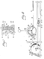
- a roll 9 of plastics foil 10 which forms the outer layer of the finished diaper.
- Journalled on a frame 11 forming part of the frame structure 7 is a guide roller 13 which extends parallel with the shaft 12 of the roll 9 and over which the web 10 passes in towards and beneath a further free- running guide roller 14, which guides the web 10 upwardly and on to the peripheral surface of a drum 15 driven at a constant speed in the direction of arrow C.
- the guide roller 14 preferably lies against the circular-cylindrical peripheral surface of the drum 15 and presses the web against the elastically tensioned ribbon in a manner hereinafter described.
- the plastics web 10 passes from the drum 15 beneath a guide roller 16 and has then been provided on its undersurface with the somewhat tensioned elastic ribbons, from whence it passes over a freely-rotating reversing roller 17.
- the web 10 then passes from the reversing roller towards a working station of well known kind, in which the elastic ribbons lie on the upper side of the plastics web.
- a working station or a sequence of sequential working stations, there is applied a relatively thick layer of liquid-absorbent soft material, for example fluffed cellulose, together with the inner layer, whereafter the outer and inner layers are joined together and a finished diaper according to Figure 1 for example is punched from the resultant laminate.
- an electric motor 18 whose output shaft carries a sprocket wheel 19 which drives, via a chain 20, a further sprocket wheel 21 firmly mounted on a drive shaft 22 journalled in the frame structure 7 ( Figure 4).
- the drive shaft 22 also drives a chain 23 via a sprocket wheel (not shown) and a drive roller (not shown) for a drive belt 25, via a gearing 24, said belt extending over an upper drive roller 26 ( Figure 2).
- the drive rollers of the drive belt 25 are journalled on a frame 27 which can be pivoted around the lower drive roller and urged against the roll 9 carrying the plastics web with the aid of means not shown here.
- the drive belt 25 abutting the periphery of the roll 9 transfers a given drive force to the heavy roll 9, in order to facilitate with drawal of the web 10 therefrom.
- a web take-off force is applied to the web 10 partly through the drum 15, against which the web 10 is held pressed by means of the guide rollers 14 and 16, and partly by means of drive rollers (not shown) between which the web passes and which, for example, are arranged upstream of the reversing roll 17.
- the drive shaft 22 is also provided with a sprocket wheel 28 ( Figure 4) which is firmly mounted on said shaft and which drives a sprocket wheel 30 via a chain 29.
- the chain wheel 30 is firmly mounted on a rotatable shaft 31 which extends transversely through the whole frame structure 7 and the end portions of which are rotatably journalled in bearing boxes located in vertical posts 32 and 33 fixed in the frame structure 7. Journalled on both ends of the shaft 31 are identical guide cylinders 34 and 35 respectively.
- Each guide cylinder is provided with a respective continuous cam groove 36 and 37 comprising two identical parts each including 180° of the guide cylinder. Each such groove part has a form which corresponds to the predetermined paths 49, 50 of the elastic ribbon to be attached to the plastics web 10 (cf Figure 1).
- the two guide cylinders 34, 35 arranged on the outer surfaces of the frame structure 7 are firmly mounted on the shaft 31 and thus rotate synchronously with one another.
- the elastic ribbons attached to both sides of the diaper in the longitudinal direction thereof lie fully symmetrically around the longitudinal axis of the diaper.
- the two grooves 36 and 37 will have a correspondingly different curvature.
- the drum 15 is non-rotatably mounted on the shaft 31 in the frame 7 by means of robust spokes 38, 39 and 40 which extend from the centre part of the drum 15 and the inner end parts of which are joined with a hub 41 securely keyed to the shaft 31.
- the drum 15 has open ends through which are inserted two suction boxes 42 and 43 respectively.
- Each suction box 42, 43 has an upper edge part 44 (cf Figure 3) adapted to the inner surface 45 of the drum 15, said edge part 44 defining an open side of a respective box. Other sides are closed.
- the suction box 42 is connected to a suction source 47 via a suction pipe 46, while the suction box 43 is connected to the suction source 47 via a suction pipe 48.
- the suction source comprises, for example, a powerful fan or centrifugal pump adapted to create a desired subpressure in the two suction boxes 42 and 43 arranged on both sides of the carrier means 38, 39, 40 of the drum 15.
- the peripheral surface of the drum 15 has arranged therein grooves 49 and 50 defining said predetermined paths and of the same configuration as the cam grooves 36 and 37 respectively.
- Each of these grooves 49 and 50 is intended to accomodate at least one elastic ribbon 51, see in particular Figure 4, which are withdrawn from a reel 52 by means of two mutually abutting driven rollers 53 and 54, or drawn from a box and fed in between the rollers 53, 54.
- the two rollers 53 and 54 are journalled in the frame structure 7 and are driven from a directcurrent motor 55, as indicated in Figure 4. Journalled in the frame structure 7 in its transverse direction are two guides 56 and 57, on which two carriages 58 and 59 can be moved.
- Each carriage, 58, 59 is provided with a dogging means, for example the dogging means 60 of the carriage 59, which are firmly mounted on the carriage and project into the respective allotted cam groove 36 or 37.
- a dogging means for example the dogging means 60 of the carriage 59, which are firmly mounted on the carriage and project into the respective allotted cam groove 36 or 37.
- the shaft 31 rotates, and therewith also the drum 15 and the guide cylinders 34 and 35
- the two carriages 58 and 49 are moved towards and away from each other on the two guides 56, 57.
- Mounted on the carriage 58 and 59 are respective adhesive nozzles 61 and 62, said nozzles being located such that their outlet orifices follow the ribbon grooves 49 and 50 during movement of the carriages.
- the two nozzles 61 and 62 are supplied with hot thermoplastic adhesive under pressure through conduits, for example the conduit 63 in Figure 3 from a source not shown. Since two elastic ribbons 51 are to be withdrawn, one for each groove 49, 50, two reels 52 are provided. Each ribbon is withdrawn from its respective reel by means of the two drive rollers 53, 54 which hold the ribbon firmly therebetween and feed the ribbon over a guide roller 64 into its allotted groove 49, 50.
- the shaft 31, and therewith the drum 15 and the guide cylinders 34, 35 are assumed here to be driven at a constant, given speed which is adapted to the rate at which work is carried out in subsequent stations.
- each elastic ribbon 51 is to be attached to the plastics web 10 in a somewhat tensioned state, and possibly under a tension which varies along the ribbon length, the rollers 53 and 54 must be driven at a speed such that the speed at which the ribbon 51 is advanced is slower than the peripheral speed of the drum 15.
- adhesive is applied to the upper surface of the ribbon and the ribbon pressed by the pressure roller 14 onto the undersurface of the plastics web 10.
- the illustrated embodiment includes a cooling box 65 ( Figure 3) which is connected to a source 66 of cooling air and arranged above the drum 15 in order to cool the hotmelt adhesive as quickly as possible.
- the ribbon 5 which as will be understood need not be planar but may have the form of a filament of substantially circular cross-section, in the groove on the drum 15 through a distance equal to about 180°, although this distance may naturally vary, inter alia in dependence on the diameter of the drum and the length of the diaper.
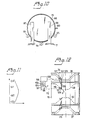
- Figures 5 and 6 illustrate a pronounced curvature in the groove 49 and the manner in which an inserted ribbon 51 having a width exceeding its thickness behaves.
- the tension in the ribbon 51 is greater on the outside of the centre line 67 of the groove 49 than on the inside of the centre line, and as mentioned in the introduction and as illustrated in Figure 6 the ribbon 51 will be lifted up on the outside of the curve, and in an extreme case will be rolled or tilted over the radially inward ribbon portion, resulting in poor adhesion to the plastics web 10, or in a practically negligible bond.
- suction boxes 42 and 43 and suction openings for example the openings 68, 69, 70, 71 in the preferably planar bottom 72 of the grooves 49 and 50, extending substantially along the whole length of the groove ( Figure 7) are arranged in accordance with the invention to avoid this drawback.
- These openings 68, 71 communicate with the respective interiors of the suction boxes and will thus draw the nonadhesive surface of the entire ribbon 51 firmly against the groove bottom, therewith to hold the ribbon in a planar and non-slidable position in the groove.
- the openings must at least be arranged on the groove portion 49' ( Figure 7) distal from the centre of curvature, although openings, such as the opening 73, 74, 75 and 76, are also preferably arranged on the innermost groove part 49" ( Figure 8), thereby to obtain positive retention of the edge portions of the ribbon on both sides of the centre line, which further reduces the risk of the tensioned ribbon from sliding and tilting in the groove and therewith moving relative to the web 10 which moves at a constant speed.
- the inner and outer openings are suitably displaced relative to one another, as illustrated in Figure 8, and in one preferred embodiment the inner and outer openings are connected with one another by means of shallow grooves, for example the grooves 80 and 81, which cross the groove bottom 22.
- the suction openings in the outer and inner rows respectively may be connected together directly, as illustrated by the broken lines 82 and 83 which indicate shallow grooves formed by grinding the groove bottom 72. Practical tests have shown that such grooves 82 extending in the longitudinal direction of the tape 51 between the suction openings provide a good effect with respect to preventing upward bending of the outer ribbon edge, shown in Figure 6, while grooves 81 extending across the width of the ribbon, on the other hand, are much more effective in preventing sliding of the ribbon than the grooves 82.
- FIG. 3 The principle by which the ribbon 51 is imparted in the illustrated embodiment with a varying tension such that the finished diaper, or some other manufactured liquid-absorbing product, has a region of greatest tension in the crutch part of the diaper is illustrated in a highly simplified manner in Figure 3.
- the figure illustrates the cam grooves 36 of the guide cylinder 34, these grooves accomodating a dogging means 84, which in turn adjusts a potentiometer 85 fixedly mounted in relation to the cam groove 36.
- the potentiometer 85 regulates the voltage to the direct current motor 55 which drives the feed rollers 53, 54.
- the ribbon 51 When the setting means of the potentiometer 85 is located within the region 36'the ribbon 51 shall be imparted a continuously increasing tensile force so that when the setting means reaches the horizontal region 36" shown in the figure the achieved maximum tension is maintained throughout the whole of the crutch part G1-G2 ( Figure 1).
- the setting means 84 then reaches the upwardly directed part of the cam groove and the tensile force in the ribbon 51 is progressively decreased to the minimum, constantly maintained tensile force, i. e. the speed of the motor 55 is progressively increased.
- the ribbon tension may be given the appearance illustrated in Figure 11, for example, in which the length markings G1-G4 shown in Figure 1 are plotted along the Y axis and the tensile force is plotted along the X-axis.
- the ribbon or band is held by suction forces along its length in the predetermined curved path 49 or 50 and therefore the varying tension forces will be maintained.
- the pressure in the suction openings lying closest to the groove end 86 will lie at atmospheric pressure and the web, together with the ribbon is able to pass readily from the drum 15 and beneath the guide roller 16 while the remaining groove length lying within the suction-box opening is subjected to suction force.
- the ribbon 51 while lying on the outer cylindrical surface of the drum 15 will be held firmly by suction at the same time as all suction effect ceases on the part departing from the drum, this part thus not being subjected to forces capable of pulling the ribbon loose from the web 10.
- the grooves illustrated in Figure 8 connecting the suction openings with one another are so shallow that the ribbon material is drawn down into the grooves and seals thereagainst.
- FIGS 9 and 10 illustrate a modified drum having a rear side wall 90 with a hub 91 to which the drive shaft 31 is firmly connected.
- the hub 90 is mounted for rotation in a journal bearing 92 attached to the machine-frame structure 7 in a manner not shown.
- the other end part of the drum 15 is open and freely-running rollers 93, '94, 95 are journalled in the frame structure and support this end part.
- the suction box 96 is carried by two bracket means 97, 98, firmly mounted to the frame structure 7.
- the interior of the suction box 96 is connected to a suction source via a conduit 100.
- a suction source Arranged in the outer cylindrical surface of the suction box 96 are two openings which include about 180° of said outer cylindrical surface and lie in the movement path of the groove 49 and 50 respectively.
- the opening 101 for the groove 50 is shown in Figure 9.
- the guide cylinder 34 in Figure 4 is assumed to be provided, while sensing of the guide curve 36 is assumed to take place with the aid of a photocell, which in turn delivers a control signal to two electric motors for guiding the two aforementioned carriages 58 and 59 towards and away from each other.
- the curve 36 need not comprise a milled groove, but may comprise a track marked with a colouring agent.
- the requisite movements of the carriages 58 and 59 may also be effected with the aid of a dataprocessor containing the requisite control information.
- Figure 12 illustrates the one carriage 59, on which there is rotatably mounted a table 103, which is arranged for rotation about a central shaft or axis 104.
- the table 103 carries the adhesive nozzle 62, a guide roller 64 and drive rollers 53, 54, ( Figures 3 and 4) and these elements will thus be rotated as a unit and determine the infeed direction of the ribbon 51 and the adhesive string, this direction being indicated in Figure 12 by the arrow F and corresponds to the direction F' of the groove 49 at the infeed location.
- the carriage 58 ( Figure 4) is provided with a corresponding table, carrying the adhesive nozzle 61 and the ribbon-feed and ribbon-alignment rollers for the ribbon 51, which is introduced into the groove 50.
- Figure 12 illustrates the dogging means 60 ( Figure 4) which, as previously described, guides the movement of carriage 59 parallel with the axis of the drum 15 and which comprises a freely rotatable wheel having a diameter corresponding to the width of the cam groove 36.
- the wheel 60 is rotatably journalled centrally on a pivot arm 105, one end of which is pivotably connected to a guide arm 106 and the other end of which carries a freely rotatable follower wheel 107 having a smaller diameter than the width of the cam groove 36, so that the guide means formed by the wheels 60, 107 can pass freely through curves of small radii.
- a tension spring 108 Arranged between the arm 105 and the arm 106 is a tension spring 108.
- the described and well known parallelogram-guide mechanism ensures that the rotary axis of the wheel 110 always lies at right angles to F1, and when the holder 111 is connected to the table 103 via a linkage system 112, the table 103 will thus always be adjusted in dependence on the curvature of the groove part to which ribbon and adhesive are fed at that moment in time.
- the table on the carriage not shown in Figure 13 is guided with the aid of a corresponding parallelogram-link system.
- cam grooves 36 and 37 there can be used a purely electronic guide means incorporating guide information stored in a dataprocessor and utilised to instigate translatory movements of the carriages 58, 59 and rotatory movements of the tables, for examples the table 103, via drive motors.
- Such arriving movement is particularly suitable when the fixed paths 49, 50 are not formed by grooves provided in the outer cylindrical surface of the drum 15, but simply have the form of the described suction openings in said surface.
- the ribbon must be placed analogously with what has been described with reference to Figure 12, i. e. the position of the ribbon at the point of application must, at each moment in time, correspond to the determined shape of the path 49 and 50 respectively.
Abstract
Description
- The present invention relates to an arrangement for bonding a tensioned elastic ribbon with the aid of an adhesive along a given curved path on a plastics web in the manufacture of diapers or like liquid-absorbing products, the ribbon being introduced by feed-in means onto a rotatable cylindrical drum driven by drive means in correspondence with the given path, and brought together with the plastics web which is moved through a given distance on the peripheral surface of the drum, there being provided in the peripheral surface of the drum an array of suction openings in correspondence with the given path, and which suction openings communicate with a suction source in a manner to retain the ribbon in its position on the peripheral surface of the drum, and means for breaking the connection between the suction openings and the suction source as a respective suction opening completes its passage along said path and guide means arranged to displace the ribbon along the peripheral surface of the drum and in the axial direction of the drum in correspondence with the curvature of the given path.
- Such an arrangement is known from EP-A-108 173. In this known arrangement the tensioned ribbon is placed along a straight path on the periphery of the drum and the ends of the ribbon are drawn firmly against the drum periphery by suction, so that the ribbon is held stretched and in contact with the plastics web until the adhesive has hardened A serious drawback with this known arrangement is that the ribbon is under uniform tension along the whole of its length, and that consequently the plastics web is gathered uniformly along the whole length of the resultant diaper or like absorbent. A general desire is one of enabling the ribbon tension to be varied, so that gathering of the diaper or like absorbent is more pronounced in the crutch part thereof, as described for example in EPC-Patent publication No 0 027 303. The arrangement described in this patent specification lacks means for holding the ribbon in tension, and consequently there is a danger that the ribbon will contract relative to the plastics web before the adhesive has completely hardened, which results in equalization of the tension along the whole of the ribbon, this problem being particularly serious when the greatest tension is located at the central part of the ribbon, coinciding with the crutch part of the diaper. Moreover, in the manufacture of diapers the greatest possible effort is made to arrange the elastic ribbons so that they follow the shape of the body to the greatest possible extent, partly to obtain the best possible sealing effect and partly so that the diaper is comfortable to wear. This necessitates placing the ribbon along a curved path on the drum, which then creates the problem of the ribbon twisting or tilting due to the fact that the width of a normal ribbon is greater than its thickness. Such twisting or tilting of the ribbon results in poor adhesion between the plastics web and the ribbon. Consequently, in order to enable ribbons to be attached along curved paths the use of ribbons of substantially circular cross-section has been proposed, as disclosed in US Patent Specification No. 3 828 367 for example.
- Accordingly, the main object of this invention is to provide an arrangement of the kind described in the introduction which will enable ribbons to be attached along curved paths and which will permit such ribbons to have varying tension over the whole of the bonding area.
- This main object is realised fully with the arrangement according to the invention described hereinafter with reference to an embodiment thereof illustrated in the accompanying drawings, in which
- Figure 1 illustrates a type of diaper incorporating curved elastic ribbons ;
- Figure 2 illustrates in side view and in a greatly simplified manner an arrangement according to the invention with certain details omitted ;
- Figure 3 illustrates a detail of the arrangement shown in Figure 2 ;
- Figure 4 illustrates the arrangement of Figure 2 as a whole, with the ribbon transfer drum partially cut away ;
- Figure 5 illustrates part of a curved groove located on the drum periphery having a ribbon inserted in said groove, in accordance with known techniques ;
- Figure 6 is a sectional view taken on the line Vl-VI in Figure 5 ;
- Figure 7 illustrates part of a groove located in the drum periphery and formed in accordance with the invention ;
- Figure 8 illustrates a modified groove form ;
- Figure 9 illustrates a modified drum and suction means ;
- Figure 10 illustrates the arrangement of Figure 9, seen towards the open end of the drum ;
- Figure 11 is a diagram showing an example of a ribbon tension curve ; and
- Figure 12 illustrates a ribbon control mechanism and an associated adhesive nozzle.
- In order to facilitate an understanding of the invention there is shown in Figure 1 an embodiment of a diaper of hour-glass configuration which has been chosen by way of example only and which has been provided with elastic tape in the crutch and side portions thereof so that when work the diaper seals as tightly as possible against the body.
- The
disposable diaper 1 illustrated in Figure 1 comprises a liquid-permeableinner layer 2 of nonwoven or like material, i. e. a layer which faces the body of the wearer, and an impervious outer layer ortopsheet 3 made of plastics film or plastics foil. Arranged between thelayers absorbent pad 4 of fluffed cellulose or like material. Elastic curved ribbons orfilaments 5 are incorporated in the mutually joined side portions orpanels 6 of the twolayers pad 4. In the illustrated embodiment the ribbons orfilaments 5, which are made of rubber or like material for example, are attached to theplastics web 3 in curved lines with the aid of an adhesive and prior to being attached are stretched so that after being firmly bonded to the plastics web they draw together the crutch part A of the diaper and optionally also the side parts B thereof, so that the edges of the diaper are gathered together, thereby to seal more efficiently against the body of the wearer. The stretchedelastic ribbons 5 are laid along the outer contours of the diaper. Although not shown, each diaper may be provided with an elastic waist band firmly adhered to the two end parts of the outer plastics foil. - It will be assumed hereinafter that the elastic ribbons comprise thin rubber ribbons which are bonded to the plastics web with a hot-melt adhesive, although it will be understood that the elastic ribbons may comprise any suitable materials whatsoever, such as, for example, an ethylene-propylenerubber mixture (EPR) with an ethylene vinyl acetate extruded into thin ribbons which are stretched while applying heat thereto. The stretched ribbon is then cooled and remains stretched while retaining its elasticity. When subsequently heated the ribbon returns to its original length.
- The hot-melt adhesive can be replaced, for example, with double-sided adhesive foil, one surface of which adheres to the ribbon and the other surface of which is brought together with the aforesaid plastics web.
- The embodiment of the invention chosen by way of example is described hereinafter with reference to Figures 2, 3 and 4.
- Journalled in a
frame structure 7 on aroll holder 8 is aroll 9 ofplastics foil 10, which forms the outer layer of the finished diaper. Journalled on aframe 11 forming part of theframe structure 7 is aguide roller 13 which extends parallel with theshaft 12 of theroll 9 and over which theweb 10 passes in towards and beneath a further free- runningguide roller 14, which guides theweb 10 upwardly and on to the peripheral surface of adrum 15 driven at a constant speed in the direction of arrow C. Theguide roller 14 preferably lies against the circular-cylindrical peripheral surface of thedrum 15 and presses the web against the elastically tensioned ribbon in a manner hereinafter described. - The
plastics web 10 passes from thedrum 15 beneath aguide roller 16 and has then been provided on its undersurface with the somewhat tensioned elastic ribbons, from whence it passes over a freely-rotating reversingroller 17. Theweb 10 then passes from the reversing roller towards a working station of well known kind, in which the elastic ribbons lie on the upper side of the plastics web. In this working station, or a sequence of sequential working stations, there is applied a relatively thick layer of liquid-absorbent soft material, for example fluffed cellulose, together with the inner layer, whereafter the outer and inner layers are joined together and a finished diaper according to Figure 1 for example is punched from the resultant laminate. - Mounted in the
frame structure 7 is anelectric motor 18 whose output shaft carries asprocket wheel 19 which drives, via achain 20, afurther sprocket wheel 21 firmly mounted on adrive shaft 22 journalled in the frame structure 7 (Figure 4). Thedrive shaft 22 also drives achain 23 via a sprocket wheel (not shown) and a drive roller (not shown) for adrive belt 25, via agearing 24, said belt extending over an upper drive roller 26 (Figure 2). The drive rollers of thedrive belt 25 are journalled on aframe 27 which can be pivoted around the lower drive roller and urged against theroll 9 carrying the plastics web with the aid of means not shown here. Thedrive belt 25 abutting the periphery of theroll 9 transfers a given drive force to theheavy roll 9, in order to facilitate with drawal of theweb 10 therefrom. A web take-off force is applied to theweb 10 partly through thedrum 15, against which theweb 10 is held pressed by means of theguide rollers reversing roll 17. Thedrive shaft 22 is also provided with a sprocket wheel 28 (Figure 4) which is firmly mounted on said shaft and which drives asprocket wheel 30 via a chain 29. Thechain wheel 30 is firmly mounted on arotatable shaft 31 which extends transversely through thewhole frame structure 7 and the end portions of which are rotatably journalled in bearing boxes located invertical posts frame structure 7. Journalled on both ends of theshaft 31 areidentical guide cylinders continuous cam groove predetermined paths guide cylinders frame structure 7 are firmly mounted on theshaft 31 and thus rotate synchronously with one another. It will be noted that it is assumed here that the elastic ribbons attached to both sides of the diaper in the longitudinal direction thereof lie fully symmetrically around the longitudinal axis of the diaper. Naturally, if the ribbon or ribbons on one side of the diaper are required to have a curvature which deviates from the ribbon or ribbons on the other side of said diaper, the twogrooves drum 15 is non-rotatably mounted on theshaft 31 in theframe 7 by means ofrobust spokes drum 15 and the inner end parts of which are joined with ahub 41 securely keyed to theshaft 31. Thedrum 15 has open ends through which are inserted twosuction boxes suction box inner surface 45 of thedrum 15, said edge part 44 defining an open side of a respective box. Other sides are closed. Thesuction box 42 is connected to asuction source 47 via asuction pipe 46, while thesuction box 43 is connected to thesuction source 47 via asuction pipe 48. The suction source comprises, for example, a powerful fan or centrifugal pump adapted to create a desired subpressure in the twosuction boxes drum 15. - In the illustrated embodiment the peripheral surface of the
drum 15 has arranged thereingrooves cam grooves grooves elastic ribbon 51, see in particular Figure 4, which are withdrawn from a reel 52 by means of two mutually abutting drivenrollers rollers rollers frame structure 7 and are driven from adirectcurrent motor 55, as indicated in Figure 4. Journalled in theframe structure 7 in its transverse direction are twoguides carriages carriage 59, which are firmly mounted on the carriage and project into the respective allottedcam groove shaft 31 rotates, and therewith also thedrum 15 and theguide cylinders carriages guides carriage adhesive nozzles ribbon grooves nozzles conduit 63 in Figure 3 from a source not shown. Since twoelastic ribbons 51 are to be withdrawn, one for eachgroove drive rollers guide roller 64 into its allottedgroove shaft 31, and therewith thedrum 15 and theguide cylinders elastic ribbon 51 is to be attached to theplastics web 10 in a somewhat tensioned state, and possibly under a tension which varies along the ribbon length, therollers ribbon 51 is advanced is slower than the peripheral speed of thedrum 15. As will be seen from Figure 3 subsequent torespective ribbons 51 leaving theguide roller 64 and entering their respective grooves on thedrum 15 in a substantially tangential direction, adhesive is applied to the upper surface of the ribbon and the ribbon pressed by thepressure roller 14 onto the undersurface of theplastics web 10. The illustrated embodiment includes a cooling box 65 (Figure 3) which is connected to asource 66 of cooling air and arranged above thedrum 15 in order to cool the hotmelt adhesive as quickly as possible. It is also conceivable to hold theribbon 5, which as will be understood need not be planar but may have the form of a filament of substantially circular cross-section, in the groove on thedrum 15 through a distance equal to about 180°, although this distance may naturally vary, inter alia in dependence on the diameter of the drum and the length of the diaper. - Figures 5 and 6 illustrate a pronounced curvature in the
groove 49 and the manner in which an insertedribbon 51 having a width exceeding its thickness behaves. The tension in theribbon 51 is greater on the outside of thecentre line 67 of thegroove 49 than on the inside of the centre line, and as mentioned in the introduction and as illustrated in Figure 6 theribbon 51 will be lifted up on the outside of the curve, and in an extreme case will be rolled or tilted over the radially inward ribbon portion, resulting in poor adhesion to theplastics web 10, or in a practically negligible bond. - The
aforesaid suction boxes openings planar bottom 72 of thegrooves openings entire ribbon 51 firmly against the groove bottom, therewith to hold the ribbon in a planar and non-slidable position in the groove. When thegroove 49 is completely or partially curved as illustrated in Figure 7, the openings must at least be arranged on the groove portion 49' (Figure 7) distal from the centre of curvature, although openings, such as theopening innermost groove part 49" (Figure 8), thereby to obtain positive retention of the edge portions of the ribbon on both sides of the centre line, which further reduces the risk of the tensioned ribbon from sliding and tilting in the groove and therewith moving relative to theweb 10 which moves at a constant speed. The inner and outer openings are suitably displaced relative to one another, as illustrated in Figure 8, and in one preferred embodiment the inner and outer openings are connected with one another by means of shallow grooves, for example thegrooves 80 and 81, which cross thegroove bottom 22. The suction openings in the outer and inner rows respectively may be connected together directly, as illustrated by thebroken lines groove bottom 72. Practical tests have shown thatsuch grooves 82 extending in the longitudinal direction of thetape 51 between the suction openings provide a good effect with respect to preventing upward bending of the outer ribbon edge, shown in Figure 6, whilegrooves 81 extending across the width of the ribbon, on the other hand, are much more effective in preventing sliding of the ribbon than thegrooves 82. - This slipping or sliding of the ribbon, caused by equalisation of the tension force in the ribbon, is particularly troublesome when the crutch part of a diaper is to have a more pronounced gathering than the side portions of the diaper, i. e. when the ribbons to be attached to the
plastics web 10 shall have a higher degree of tension within the ultimate crutch part, which is corresponded by the distance G1-G2 in Figure 1 and the corresponding distance ongrooves - The principle by which the
ribbon 51 is imparted in the illustrated embodiment with a varying tension such that the finished diaper, or some other manufactured liquid-absorbing product, has a region of greatest tension in the crutch part of the diaper is illustrated in a highly simplified manner in Figure 3. The figure illustrates thecam grooves 36 of theguide cylinder 34, these grooves accomodating a dogging means 84, which in turn adjusts apotentiometer 85 fixedly mounted in relation to thecam groove 36. Thepotentiometer 85 regulates the voltage to the directcurrent motor 55 which drives thefeed rollers potentiometer 85 is located within theregion 36'the ribbon 51 shall be imparted a continuously increasing tensile force so that when the setting means reaches thehorizontal region 36" shown in the figure the achieved maximum tension is maintained throughout the whole of the crutch part G1-G2 (Figure 1). This means that the outfeed speed of thefeed rollers potentiometer 85 controls themotor 55 in a manner to progressively decrease in speed until the maximum tensile force is achieved. The setting means 84 then reaches the upwardly directed part of the cam groove and the tensile force in theribbon 51 is progressively decreased to the minimum, constantly maintained tensile force, i. e. the speed of themotor 55 is progressively increased. - It is possible with the aid of this arrangement to vary the ribbon tension once or a number of times as the ribbon is being attached to the
plastics web 10, so that the side parts of the finished products have suitably adapted forces which hold said parts together to provide the best possible seal. The ribbon tension may be given the appearance illustrated in Figure 11, for example, in which the length markings G1-G4 shown in Figure 1 are plotted along the Y axis and the tensile force is plotted along the X-axis. The ribbon or band is held by suction forces along its length in the predeterminedcurved path - Variations in tension in the
ribbon 51 bonded to theweb 10 may, of course, be achieved with the aid of purely mechanical means, for example, by means of an eccentric-cylinder mechanism ac- . cording to the EPC-Patent Specification No. 0 027 303. - As before mentioned these variations in tensile stress become equalised as a result of « shrinkage of the
ribbon 51 relative to theweb 10 when using a groove which lacks the aforedescribed suction feature, due to the fact that the binder does not harden fully, even when an expensive hot-melt adhesive is used. When a double-sided adhesive tape is used for example, the time taken to establish a bond is so long that unless the suction technique according to the invention is applied it is not possible to avoid sliding of the ribbon under tension. The subpressure for holding the stretched ribbon by suction is controlled automatically, so that the ribbon is captured by openings through which a suction force is exerted at the correct moment in time, and the ribbon is then released by successively removing the subpressure. - The end 86 of the upper groove part of the
groove 49, and also theend 87 have been marked in Figure 4. When the end 86 of the groove reaches the left edge part 88 (Figure 3) of an associated suction box during rotation of thedrum 15, the suction openings of the groove bottom 72 are connected with the interior of the suction box and therewith draw the end of theribbon 51 firmly against the groove bottom, and as the drum is rotated further in a clockwise direction in Figure 3, further suction openings will lie above the suction box and therewith cause the ribbon to be held firmly by suction along the whole of its length. When theweb 10 with theelastic ribbon 51 provided with an adhesive undersurface is rotated about 180° the original start end 86 will have reached and passed theright edge part 89 of the suction box (Figure 2). - As soon as the groove end 86 has passed this edge part, the pressure in the suction openings lying closest to the groove end 86 will lie at atmospheric pressure and the web, together with the ribbon is able to pass readily from the
drum 15 and beneath theguide roller 16 while the remaining groove length lying within the suction-box opening is subjected to suction force. Thus, in practice theribbon 51 while lying on the outer cylindrical surface of thedrum 15 will be held firmly by suction at the same time as all suction effect ceases on the part departing from the drum, this part thus not being subjected to forces capable of pulling the ribbon loose from theweb 10. As will be understood, the grooves illustrated in Figure 8 connecting the suction openings with one another are so shallow that the ribbon material is drawn down into the grooves and seals thereagainst. - The described arrangement merely constitutes an embodiment of the invention and it will be understood that various modifications can be made without departing from the concept of the invention.
- Figures 9 and 10 illustrate a modified drum having a
rear side wall 90 with ahub 91 to which thedrive shaft 31 is firmly connected. Thehub 90 is mounted for rotation in a journal bearing 92 attached to the machine-frame structure 7 in a manner not shown. The other end part of thedrum 15 is open and freely-runningrollers 93, '94, 95 are journalled in the frame structure and support this end part. Inserted in thedrum 15, which is shown partly in section in Figure 9, is acylindrical suction box 96 which extends beneath the twogrooves suction box 96 is carried by two bracket means 97, 98, firmly mounted to theframe structure 7. - The interior of the
suction box 96 is connected to a suction source via aconduit 100. Arranged in the outer cylindrical surface of thesuction box 96 are two openings which include about 180° of said outer cylindrical surface and lie in the movement path of thegroove opening 101 for thegroove 50 is shown in Figure 9. When thedrum 15 is rotated around the cylindrical,stationary suction box 96, theend edge 102 thereof will successively interrupt the connection of the holes ingroove guide cylinder 34 in Figure 4 is assumed to be provided, while sensing of theguide curve 36 is assumed to take place with the aid of a photocell, which in turn delivers a control signal to two electric motors for guiding the twoaforementioned carriages curve 36 need not comprise a milled groove, but may comprise a track marked with a colouring agent. The requisite movements of thecarriages - When the ribbon is to be applied in a curved pattern according to the invention, for example as indicated by the
grooves ribbon 51, an advantage is gained when the infeed of respective ribbons on thedrum 15 takes place in the direction of the groove, i. e. parallel with the groove direction at the infeed location. Such infeed is, of course, also carried out when the path simply consists of a marking orimaginary path adhesive nozzle carriage 59, on which there is rotatably mounted a table 103, which is arranged for rotation about a central shaft oraxis 104. The table 103 carries theadhesive nozzle 62, aguide roller 64 and driverollers ribbon 51 and the adhesive string, this direction being indicated in Figure 12 by the arrow F and corresponds to the direction F' of thegroove 49 at the infeed location. Although not shown, the carriage 58 (Figure 4) is provided with a corresponding table, carrying theadhesive nozzle 61 and the ribbon-feed and ribbon-alignment rollers for theribbon 51, which is introduced into thegroove 50. Figure 12 illustrates the dogging means 60 (Figure 4) which, as previously described, guides the movement ofcarriage 59 parallel with the axis of thedrum 15 and which comprises a freely rotatable wheel having a diameter corresponding to the width of thecam groove 36. Thewheel 60 is rotatably journalled centrally on apivot arm 105, one end of which is pivotably connected to aguide arm 106 and the other end of which carries a freelyrotatable follower wheel 107 having a smaller diameter than the width of thecam groove 36, so that the guide means formed by thewheels arm 105 and thearm 106 is atension spring 108. which holds thewheel 107 pressed against the inner wall of thegroove 36. The other end of theguide arm 106 is pivotably connected to afurther pivot arm 109 the free end of which carries afollower wheel 110 which co-acts with thegroove 49. Thefollower wheel 110 is journalled in aholder 111. The described and well known parallelogram-guide mechanism ensures that the rotary axis of thewheel 110 always lies at right angles to F1, and when theholder 111 is connected to the table 103 via alinkage system 112, the table 103 will thus always be adjusted in dependence on the curvature of the groove part to which ribbon and adhesive are fed at that moment in time. The table on the carriage not shown in Figure 13 is guided with the aid of a corresponding parallelogram-link system. - As previously indicated instead of the
cam grooves carriages - Such datorised movement is particularly suitable when the fixed
paths drum 15, but simply have the form of the described suction openings in said surface. In this case the ribbon must be placed analogously with what has been described with reference to Figure 12, i. e. the position of the ribbon at the point of application must, at each moment in time, correspond to the determined shape of thepath
Claims (9)
Priority Applications (1)
| Application Number | Priority Date | Filing Date | Title |
|---|---|---|---|
| AT85850323T ATE40510T1 (en) | 1984-11-28 | 1985-10-15 | METHOD OF ATTACHING AN ELASTIC ELEMENT TO A PLASTIC SHEET USING ADHESIVE. |
Applications Claiming Priority (2)
| Application Number | Priority Date | Filing Date | Title |
|---|---|---|---|
| SE8405999 | 1984-11-28 | ||
| SE8405999A SE449820B (en) | 1984-11-28 | 1984-11-28 | DEVICE FOR ADMINISTRATIVE ADMINISTRATION TO AN ELASTIC BAND ON A PLASTIC COVER FOR MANUFACTURING BLOWS |
Publications (2)
| Publication Number | Publication Date |
|---|---|
| EP0183662A1 EP0183662A1 (en) | 1986-06-04 |
| EP0183662B1 true EP0183662B1 (en) | 1989-02-01 |
Family
ID=20357939
Family Applications (1)
| Application Number | Title | Priority Date | Filing Date |
|---|---|---|---|
| EP85850323A Expired EP0183662B1 (en) | 1984-11-28 | 1985-10-15 | An arrangement for bonding an elastic ribbon to a plastics web with the aid of an adhesive |
Country Status (9)
| Country | Link |
|---|---|
| US (1) | US4675068A (en) |
| EP (1) | EP0183662B1 (en) |
| AT (1) | ATE40510T1 (en) |
| CA (1) | CA1242629A (en) |
| DE (1) | DE3567999D1 (en) |
| DK (1) | DK549185A (en) |
| FI (1) | FI854101L (en) |
| NO (1) | NO157726C (en) |
| SE (1) | SE449820B (en) |
Families Citing this family (71)
| Publication number | Priority date | Publication date | Assignee | Title |
|---|---|---|---|---|
| US4726873A (en) * | 1985-10-28 | 1988-02-23 | Kimberly-Clark Corporation | Apparatus for applying contoured elastic to a substrate |
| US4726807A (en) * | 1986-04-10 | 1988-02-23 | Weyerhaeuser Company | Diaper with elastic margins |
| US4764242A (en) * | 1986-12-18 | 1988-08-16 | The Kendall Company | Adhesive applying apparatus |
| US4711683A (en) * | 1987-03-09 | 1987-12-08 | Paper Converting Machine Company | Method and apparatus for making elastic diapers |
| JPH0761349B2 (en) * | 1987-07-03 | 1995-07-05 | ユニ・チャ−ム株式会社 | Method and device for attaching elastic band to moving web |
| JP2609252B2 (en) * | 1987-08-18 | 1997-05-14 | ユニ・チャーム 株式会社 | Elastic band sticking device for moving web |
| US4863542A (en) * | 1988-01-19 | 1989-09-05 | Kimberly-Clark Corporation | Method and apparatus for applying discreet elastic strips to a stationary web |
| SE466938B (en) * | 1988-04-11 | 1992-05-04 | Moelnlycke Ab | DEVICE FOR CURRENTLY LAYOUT OF PRESENT ELASTIC WIRES |
| US4915767A (en) * | 1988-11-17 | 1990-04-10 | Kimberly-Clark Corporation | Apparatus for applying an elastic in a curved pattern to a moving web |
| CA2050782C (en) * | 1990-09-13 | 1997-01-28 | Takamitsu Igaue | Disposable garments and method for attachment of elastic members around leg-holes thereof |
| US5779689A (en) * | 1990-10-26 | 1998-07-14 | Peaudouce | Diapers with elasticized crotch and end regions and a process and apparatus for the continuous manufacture thereof |
| ZA92308B (en) | 1991-09-11 | 1992-10-28 | Kimberly Clark Co | Thin absorbent article having rapid uptake of liquid |
| US5389173A (en) * | 1992-12-02 | 1995-02-14 | Paper Converting Machine Company | Apparatus and process for making disposable diaper type products |
| US5500075A (en) * | 1994-04-26 | 1996-03-19 | Paragon Trade Brands, Inc. | Leg elastic applicator which maintains the spacing between the elastics substantially constant |
| CA2149700A1 (en) * | 1994-08-12 | 1996-02-13 | Brendon Frank Ribble | Method for applying an elastic member to a moving substrate |
| US6387471B1 (en) | 1999-03-31 | 2002-05-14 | Kimberly-Clark Worldwide, Inc. | Creep resistant composite elastic material with improved aesthetics, dimensional stability and inherent latency and method of producing same |
| US6547915B2 (en) | 1999-04-15 | 2003-04-15 | Kimberly-Clark Worldwide, Inc. | Creep resistant composite elastic material with improved aesthetics, dimensional stability and inherent latency and method of producing same |
| US6287409B1 (en) * | 1999-12-23 | 2001-09-11 | Kimberely-Clark Worldwide, Inc. | Methods and apparatus for applying an elastic material in a curvilinear pattern on a continuously moving substrate |
| ES2169648B1 (en) * | 2000-02-01 | 2003-02-16 | Com De Tecnologia Sanitaria S | MACHINE FOR THE MANUFACTURE OF MULTI-PAPER PRODUCTS, SUCH AS COMPRESSES, HYGIENIC PROTECTORS OR APOSITOS. |
| US6969441B2 (en) | 2000-05-15 | 2005-11-29 | Kimberly-Clark Worldwide, Inc. | Method and apparatus for producing laminated articles |
| US6833179B2 (en) | 2000-05-15 | 2004-12-21 | Kimberly-Clark Worldwide, Inc. | Targeted elastic laminate having zones of different basis weights |
| US8182457B2 (en) | 2000-05-15 | 2012-05-22 | Kimberly-Clark Worldwide, Inc. | Garment having an apparent elastic band |
| US7335273B2 (en) | 2002-12-26 | 2008-02-26 | Kimberly-Clark Worldwide, Inc. | Method of making strand-reinforced elastomeric composites |
| US7316842B2 (en) | 2002-07-02 | 2008-01-08 | Kimberly-Clark Worldwide, Inc. | High-viscosity elastomeric adhesive composition |
| US7097725B2 (en) * | 2002-10-16 | 2006-08-29 | Zuiko Corporation | Placement device |
| US7601657B2 (en) | 2003-12-31 | 2009-10-13 | Kimberly-Clark Worldwide, Inc. | Single sided stretch bonded laminates, and methods of making same |
| US8417374B2 (en) | 2004-04-19 | 2013-04-09 | Curt G. Joa, Inc. | Method and apparatus for changing speed or direction of an article |
| US7638014B2 (en) | 2004-05-21 | 2009-12-29 | Curt G. Joa, Inc. | Method of producing a pants-type diaper |
| US20060258249A1 (en) * | 2005-05-11 | 2006-11-16 | Fairbanks Jason S | Elastic laminates and process for producing same |
| US7780052B2 (en) * | 2006-05-18 | 2010-08-24 | Curt G. Joa, Inc. | Trim removal system |
| US10456302B2 (en) | 2006-05-18 | 2019-10-29 | Curt G. Joa, Inc. | Methods and apparatus for application of nested zero waste ear to traveling web |
| US9433538B2 (en) | 2006-05-18 | 2016-09-06 | Curt G. Joa, Inc. | Methods and apparatus for application of nested zero waste ear to traveling web and formation of articles using a dual cut slip unit |
| US9622918B2 (en) | 2006-05-18 | 2017-04-18 | Curt G. Joe, Inc. | Methods and apparatus for application of nested zero waste ear to traveling web |
| US7731815B2 (en) * | 2006-11-06 | 2010-06-08 | The Procter & Gamble Company | Method and apparatus for nonlinear laying of material |
| EP2486903B1 (en) | 2007-02-21 | 2023-08-30 | Curt G. Joa, Inc. | Single transfer insert placement method and apparatus |
| US9550306B2 (en) | 2007-02-21 | 2017-01-24 | Curt G. Joa, Inc. | Single transfer insert placement and apparatus with cross-direction insert placement control |
| US9944487B2 (en) | 2007-02-21 | 2018-04-17 | Curt G. Joa, Inc. | Single transfer insert placement method and apparatus |
| US9387131B2 (en) | 2007-07-20 | 2016-07-12 | Curt G. Joa, Inc. | Apparatus and method for minimizing waste and improving quality and production in web processing operations by automated threading and re-threading of web materials |
| US8398793B2 (en) | 2007-07-20 | 2013-03-19 | Curt G. Joa, Inc. | Apparatus and method for minimizing waste and improving quality and production in web processing operations |
| US8182624B2 (en) * | 2008-03-12 | 2012-05-22 | Curt G. Joa, Inc. | Registered stretch laminate and methods for forming a registered stretch laminate |
| US20100193138A1 (en) * | 2009-01-30 | 2010-08-05 | Joseph Allen Eckstein | System for High-Speed Continuous Application of a Strip Material to a Moving Sheet-Like Substrate Material at Laterally Shifting Locations |
| US20100193135A1 (en) * | 2009-01-30 | 2010-08-05 | Joseph Allen Eckstein | System and Method for High-Speed Continuous Application of a Strip Material to a Moving Sheet-Like Substrate Material at Laterally Shifting Locations |
| US8171972B2 (en) | 2009-01-30 | 2012-05-08 | The Procter & Gamble Company | Strip guide for high-speed continuous application of a strip material to a moving sheet-like substrate material at laterally shifting locations |
| US8182627B2 (en) * | 2009-01-30 | 2012-05-22 | The Procter & Gamble Company | Method for high-speed continuous application of a strip material to a substrate along an application path on the substrate |
| JP5409897B2 (en) | 2009-04-30 | 2014-02-05 | エスセーアー・ハイジーン・プロダクツ・アーベー | Method for providing an elastic web |
| US8673098B2 (en) | 2009-10-28 | 2014-03-18 | Curt G. Joa, Inc. | Method and apparatus for stretching segmented stretchable film and application of the segmented film to a moving web |
| US8460495B2 (en) | 2009-12-30 | 2013-06-11 | Curt G. Joa, Inc. | Method for producing absorbent article with stretch film side panel and application of intermittent discrete components of an absorbent article |
| US9089453B2 (en) | 2009-12-30 | 2015-07-28 | Curt G. Joa, Inc. | Method for producing absorbent article with stretch film side panel and application of intermittent discrete components of an absorbent article |
| US8663411B2 (en) | 2010-06-07 | 2014-03-04 | Curt G. Joa, Inc. | Apparatus and method for forming a pant-type diaper with refastenable side seams |
| US9603752B2 (en) | 2010-08-05 | 2017-03-28 | Curt G. Joa, Inc. | Apparatus and method for minimizing waste and improving quality and production in web processing operations by automatic cuff defect correction |
| US20120273129A1 (en) * | 2010-10-27 | 2012-11-01 | Curt G. Joa, Inc. | Apparatus and method for the application of a curved ribbon to a traveling web |
| US8702887B2 (en) | 2010-12-17 | 2014-04-22 | Kimberly-Clark Worldwide, Inc. | Apparatus for and method of applying ribbon in a nonlinear pattern to a web |
| US8720518B2 (en) | 2010-12-17 | 2014-05-13 | Kimberly-Clark Worldwide, Inc. | Apparatus for bonding ribbon in a nonlinear pattern to a web |
| US9566193B2 (en) | 2011-02-25 | 2017-02-14 | Curt G. Joa, Inc. | Methods and apparatus for forming disposable products at high speeds with small machine footprint |
| US8656817B2 (en) | 2011-03-09 | 2014-02-25 | Curt G. Joa | Multi-profile die cutting assembly |
| USD684613S1 (en) | 2011-04-14 | 2013-06-18 | Curt G. Joa, Inc. | Sliding guard structure |
| US8820380B2 (en) | 2011-07-21 | 2014-09-02 | Curt G. Joa, Inc. | Differential speed shafted machines and uses therefor, including discontinuous and continuous side by side bonding |
| BR112014012230A2 (en) | 2011-11-30 | 2017-05-30 | Procter & Gamble | small size disposable dressing diaper |
| PL2628472T3 (en) | 2012-02-20 | 2016-07-29 | Joa Curt G Inc | Method of forming bonds between discrete components of disposable articles |
| US9809414B2 (en) | 2012-04-24 | 2017-11-07 | Curt G. Joa, Inc. | Elastic break brake apparatus and method for minimizing broken elastic rethreading |
| EP2866753A1 (en) | 2012-06-29 | 2015-05-06 | The Procter & Gamble Company | System and method for high-speed continuous application of a strip material to a moving sheet-like substrate material |
| US9283683B2 (en) | 2013-07-24 | 2016-03-15 | Curt G. Joa, Inc. | Ventilated vacuum commutation structures |
| USD703712S1 (en) | 2013-08-23 | 2014-04-29 | Curt G. Joa, Inc. | Ventilated vacuum commutation structure |
| USD703247S1 (en) | 2013-08-23 | 2014-04-22 | Curt G. Joa, Inc. | Ventilated vacuum commutation structure |
| USD703711S1 (en) | 2013-08-23 | 2014-04-29 | Curt G. Joa, Inc. | Ventilated vacuum communication structure |
| USD704237S1 (en) | 2013-08-23 | 2014-05-06 | Curt G. Joa, Inc. | Ventilated vacuum commutation structure |
| USD703248S1 (en) | 2013-08-23 | 2014-04-22 | Curt G. Joa, Inc. | Ventilated vacuum commutation structure |
| US9289329B1 (en) | 2013-12-05 | 2016-03-22 | Curt G. Joa, Inc. | Method for producing pant type diapers |
| PL3325387T3 (en) | 2015-07-24 | 2022-06-20 | Curt G. Joa, Inc. | Vacuum commutation apparatus and methods |
| EP3356057A4 (en) | 2015-09-29 | 2019-05-29 | Kimberly-Clark Worldwide, Inc. | Adhesive applicator with rotary valve |
| US11737930B2 (en) | 2020-02-27 | 2023-08-29 | Curt G. Joa, Inc. | Configurable single transfer insert placement method and apparatus |
Family Cites Families (9)
| Publication number | Priority date | Publication date | Assignee | Title |
|---|---|---|---|---|
| US2782574A (en) * | 1954-09-16 | 1957-02-26 | Gen Dynamics Corp | Work holder |
| FR2112075B1 (en) * | 1970-09-18 | 1973-12-07 | Elastelle Fontanille Il | |
| FR2177425A1 (en) * | 1971-10-13 | 1973-11-09 | Elastelle Fontanille | Disposable garments - having elasticated borders |
| US4207998A (en) * | 1977-05-16 | 1980-06-17 | Bachofen & Meier, Maschinenfabrik | Vacuum roller |
| US4216687A (en) * | 1978-03-21 | 1980-08-12 | Johnson & Johnson | Method for shaping and/or cutting batts of loosely compacted fibrous materials |
| SE414883B (en) * | 1978-05-25 | 1980-08-25 | Moelnlycke Ab | SET AND DEVICE FOR CUTTING THE PIECE OF MATERIAL COURSES |
| AU5681680A (en) * | 1979-10-16 | 1981-04-30 | Riegel Textile Corp. | Diaper |
| US4479836A (en) * | 1980-05-16 | 1984-10-30 | Johnson & Johnson Baby Products Company | Method for effecting securement of alternating stretched and unstretched elastic ribbon to a moving web |
| US4360398A (en) * | 1981-03-09 | 1982-11-23 | Sabee Products, Inc. | Method for applying elastic bands to webs |
-
1984
- 1984-11-28 SE SE8405999A patent/SE449820B/en not_active IP Right Cessation
-
1985
- 1985-10-15 EP EP85850323A patent/EP0183662B1/en not_active Expired
- 1985-10-15 AT AT85850323T patent/ATE40510T1/en not_active IP Right Cessation
- 1985-10-15 DE DE8585850323T patent/DE3567999D1/en not_active Expired
- 1985-10-21 FI FI854101A patent/FI854101L/en not_active IP Right Cessation
- 1985-10-22 US US06/790,012 patent/US4675068A/en not_active Expired - Fee Related
- 1985-10-29 CA CA000494136A patent/CA1242629A/en not_active Expired
- 1985-11-27 NO NO854742A patent/NO157726C/en unknown
- 1985-11-27 DK DK549185A patent/DK549185A/en not_active Application Discontinuation
Also Published As
| Publication number | Publication date |
|---|---|
| US4675068A (en) | 1987-06-23 |
| DK549185A (en) | 1986-05-29 |
| DK549185D0 (en) | 1985-11-27 |
| EP0183662A1 (en) | 1986-06-04 |
| ATE40510T1 (en) | 1989-02-15 |
| FI854101A0 (en) | 1985-10-21 |
| FI854101L (en) | 1986-05-29 |
| NO157726C (en) | 1988-05-11 |
| NO854742L (en) | 1986-05-29 |
| NO157726B (en) | 1988-02-01 |
| DE3567999D1 (en) | 1989-03-09 |
| SE8405999D0 (en) | 1984-11-28 |
| SE8405999L (en) | 1986-05-29 |
| CA1242629A (en) | 1988-10-04 |
| SE449820B (en) | 1987-05-25 |
Similar Documents
| Publication | Publication Date | Title |
|---|---|---|
| EP0183662B1 (en) | An arrangement for bonding an elastic ribbon to a plastics web with the aid of an adhesive | |
| US5545285A (en) | Waist elastic applicator for diaper or similar article | |
| EP0449548B1 (en) | Width stretching device | |
| US5531850A (en) | Apparatus and method for applying transverse tensioned elastic | |
| US2702406A (en) | Apparatus for stretching sheet material | |
| KR0169958B1 (en) | Cross web layer application device | |
| US5660665A (en) | Rotating transfer roll with rotating extensible platen | |
| US6264132B1 (en) | Method and device for grasping part of an outer layer of a strip of material on a supply roll | |
| JPS602570A (en) | Automatic sticking device for double-sided adhesive tape | |
| JP2793166B2 (en) | Apparatus for processing a portion of web unreeled from storage web rolls | |
| CN109626084A (en) | A kind of adhesive tape rewinding machine automatic label-sticking device | |
| CA1227963A (en) | Pads and their formation | |
| US3935057A (en) | Apparatus for securing the free end of a roll of fibrous web material | |
| JPH01272803A (en) | Production of elastic tape and sticking method thereof | |
| US3326736A (en) | Method of buit joining veneers | |
| JP4583683B2 (en) | Method and apparatus for manufacturing disposable absorbent article | |
| EP1016394B1 (en) | A method and an arrangement for applying elastic | |
| US5102486A (en) | Loop applying assembly | |
| EP0827453B1 (en) | Method for converting a web on a central processing drum | |
| EP0846621A1 (en) | Apparatus for applying a gummed paper tape to a box to be closed. | |
| JPS6039618B2 (en) | Roll winding end bonding device | |
| RU2301765C2 (en) | Labeling method and apparatus | |
| JPH06209968A (en) | Installation of waist band of paper diaper | |
| CN219489102U (en) | Laser film laminating and guiding roller film feeding auxiliary structure | |
| JP2584446B2 (en) | Elastic strip fixing device for fixing stretched elastic strips to a sheet driven to move continuously, and diaper manufacturing apparatus |
Legal Events
| Date | Code | Title | Description |
|---|---|---|---|
| PUAI | Public reference made under article 153(3) epc to a published international application that has entered the european phase |
Free format text: ORIGINAL CODE: 0009012 |
|
| AK | Designated contracting states |
Kind code of ref document: A1 Designated state(s): AT BE CH DE FR GB IT LI LU NL SE |
|
| 17P | Request for examination filed |
Effective date: 19860616 |
|
| 17Q | First examination report despatched |
Effective date: 19871120 |
|
| GRAA | (expected) grant |
Free format text: ORIGINAL CODE: 0009210 |
|
| AK | Designated contracting states |
Kind code of ref document: B1 Designated state(s): AT BE CH DE FR GB IT LI LU NL SE |
|
| REF | Corresponds to: |
Ref document number: 40510 Country of ref document: AT Date of ref document: 19890215 Kind code of ref document: T |
|
| ITF | It: translation for a ep patent filed |
Owner name: DOTT. GIOVANNI LECCE & C. |
|
| ET | Fr: translation filed | ||
| REF | Corresponds to: |
Ref document number: 3567999 Country of ref document: DE Date of ref document: 19890309 |
|
| REG | Reference to a national code |
Ref country code: GB Ref legal event code: 732 |
|
| REG | Reference to a national code |
Ref country code: CH Ref legal event code: PUE Owner name: FIBRE CONVERTING MACHINERY AB |
|
| RAP2 | Party data changed (patent owner data changed or rights of a patent transferred) |
Owner name: FIBRE CONVERTING MACHINERY AB |
|
| REG | Reference to a national code |
Ref country code: FR Ref legal event code: TP |
|
| NLS | Nl: assignments of ep-patents |
Owner name: FIBRE CONVERTING MACHINERY AB TE SOLLENTUNA, ZWEDE |
|
| ITPR | It: changes in ownership of a european patent |
Owner name: CESSIONE;FIBRE CONVERTING MACHINERY AB |
|
| PGFP | Annual fee paid to national office [announced via postgrant information from national office to epo] |
Ref country code: LU Payment date: 19891011 Year of fee payment: 5 |
|
| PGFP | Annual fee paid to national office [announced via postgrant information from national office to epo] |
Ref country code: AT Payment date: 19891018 Year of fee payment: 5 |
|
| PGFP | Annual fee paid to national office [announced via postgrant information from national office to epo] |
Ref country code: BE Payment date: 19891025 Year of fee payment: 5 |
|
| PGFP | Annual fee paid to national office [announced via postgrant information from national office to epo] |
Ref country code: CH Payment date: 19891026 Year of fee payment: 5 |
|
| ITTA | It: last paid annual fee | ||
| PG25 | Lapsed in a contracting state [announced via postgrant information from national office to epo] |
Ref country code: LU Free format text: LAPSE BECAUSE OF NON-PAYMENT OF DUE FEES Effective date: 19891031 |
|
| PGFP | Annual fee paid to national office [announced via postgrant information from national office to epo] |
Ref country code: NL Payment date: 19891031 Year of fee payment: 5 Ref country code: GB Payment date: 19891031 Year of fee payment: 5 Ref country code: FR Payment date: 19891031 Year of fee payment: 5 Ref country code: DE Payment date: 19891031 Year of fee payment: 5 |
|
| PLBE | No opposition filed within time limit |
Free format text: ORIGINAL CODE: 0009261 |
|
| STAA | Information on the status of an ep patent application or granted ep patent |
Free format text: STATUS: NO OPPOSITION FILED WITHIN TIME LIMIT |
|
| 26N | No opposition filed | ||
| PGFP | Annual fee paid to national office [announced via postgrant information from national office to epo] |
Ref country code: SE Payment date: 19900927 Year of fee payment: 6 |
|
| PG25 | Lapsed in a contracting state [announced via postgrant information from national office to epo] |
Ref country code: GB Effective date: 19901015 Ref country code: AT Effective date: 19901015 |
|
| PG25 | Lapsed in a contracting state [announced via postgrant information from national office to epo] |
Ref country code: LI Effective date: 19901031 Ref country code: CH Effective date: 19901031 Ref country code: BE Effective date: 19901031 |
|
| BERE | Be: lapsed |
Owner name: FIBRE CONVERTING MACHINERY A.B. Effective date: 19901031 |
|
| PG25 | Lapsed in a contracting state [announced via postgrant information from national office to epo] |
Ref country code: NL Effective date: 19910501 |
|
| GBPC | Gb: european patent ceased through non-payment of renewal fee | ||
| NLV4 | Nl: lapsed or anulled due to non-payment of the annual fee | ||
| PG25 | Lapsed in a contracting state [announced via postgrant information from national office to epo] |
Ref country code: FR Effective date: 19910628 |
|
| REG | Reference to a national code |
Ref country code: CH Ref legal event code: PL |
|
| PG25 | Lapsed in a contracting state [announced via postgrant information from national office to epo] |
Ref country code: DE Effective date: 19910702 |
|
| REG | Reference to a national code |
Ref country code: FR Ref legal event code: ST |
|
| PG25 | Lapsed in a contracting state [announced via postgrant information from national office to epo] |
Ref country code: SE Effective date: 19911016 |
|
| EUG | Se: european patent has lapsed |
Ref document number: 85850323.8 Effective date: 19920510 |