EP0183371A2 - Multi-position bed - Google Patents
Multi-position bed Download PDFInfo
- Publication number
- EP0183371A2 EP0183371A2 EP85307488A EP85307488A EP0183371A2 EP 0183371 A2 EP0183371 A2 EP 0183371A2 EP 85307488 A EP85307488 A EP 85307488A EP 85307488 A EP85307488 A EP 85307488A EP 0183371 A2 EP0183371 A2 EP 0183371A2
- Authority
- EP
- European Patent Office
- Prior art keywords
- centre section
- bed
- side sections
- centre
- pivoted
- Prior art date
- Legal status (The legal status is an assumption and is not a legal conclusion. Google has not performed a legal analysis and makes no representation as to the accuracy of the status listed.)
- Granted
Links
Images

Classifications
-
- A—HUMAN NECESSITIES
- A61—MEDICAL OR VETERINARY SCIENCE; HYGIENE
- A61G—TRANSPORT, PERSONAL CONVEYANCES, OR ACCOMMODATION SPECIALLY ADAPTED FOR PATIENTS OR DISABLED PERSONS; OPERATING TABLES OR CHAIRS; CHAIRS FOR DENTISTRY; FUNERAL DEVICES
- A61G7/00—Beds specially adapted for nursing; Devices for lifting patients or disabled persons
- A61G7/002—Beds specially adapted for nursing; Devices for lifting patients or disabled persons having adjustable mattress frame
- A61G7/008—Beds specially adapted for nursing; Devices for lifting patients or disabled persons having adjustable mattress frame tiltable around longitudinal axis, e.g. for rolling
Definitions
- This invention relates to a multi-position bed such as is used in hospitals and for persons who by reason of physical disability or age are unable to turn or move themselves in bed. Moving such persons manually at frequent intervals is a time consuming and physically tiring activity for the nurse and hence multi position beds ,have been produced which have the facility for turning a patient and also for tilting in various directions.
- An object of the present invention is to provide a multi position bed which has many different functions but is compact and simple to operate.
- a multi-position bed comprises a base frame carrying a mattress platform which is pivoted at its ends, on pivot brackets carried on a base frame, for lateral tilting, the platform comprising a centre section and two side sections, the side sections being connected at their ends by links to end pivot frames on the centre section and being connected at intermediate points through pairs of links to a pivot bracket whereby lateral tilting of the centre section in either direction causes a side section to tilt in the other direction to produce a turning effect on a patient.
- the side sections and centre sections have interengaging features along their adjacent edges which only engage when the centre section is in its non (laterally) tilted position, but automatically disengage when lateral tilting of the centre section takes place.
- the pairs of links are easily disconnectable and one link cf each pair may then be used as a strut to rigidity the connection between each side section and the centre section so that when the centre section is laterally tilted it carries with it both of the side sections so that all three sections remain planar and tilt together.
- the lateral tilting movement of the centre section is produced by a screw and nut mechanism.
- the screw may be driven by an electric motor carried on the underside of the centre section and the nut may be mounted on one of the pivot brackets.
- a multi position bed comprises a base frame on which is pivoted a mattress platformfor lateral tilting movement, the mattress platform comprising a cross section and two side sections, the centre section being pivoted on pivot brackets below the mattress platform and the side sections being connected to the pivot bracket by links, the arrangement being such that with the links in place when the centre section is pivoted laterally in either direction the side section separates and pivots in the other direction so as to produce a turning movement of the patient, the links being disconnectable and the side and centre sections being capable of being rigidified so that when the centre section is tilted the bed frame as a whole tilts laterally without any separation of the side sections.
- the centre and side sections both have pivoted end portions which may be raised together to provide an uplifting backrest.
- the side sections and centre sections are preferably separately pivoted but so arranged that, when the centre section is lifted i laterally projecting lifting plates on the centre section will engage corresponding laterally projecting lifting plates on the side sections so that all three sections lift together.
- the side sections separate from the centre section because the lifting plates are not attached tc each other.
- pivot brackets on which the centre section is pivoted are themselves carried by lifting arms at each end of the bed, the arms being pivoted on the mattress platform.
- These arms may be operated by screw jacks in turn cperated by electric motors so that the mattress platform may be raised and lowered bodily or maybe tilted longitudinally at will.
- the lifting arms are operable by nut and screw mechanisms, there being two such mechanisms each operated by an electric motor so as to provide independent movement of the arms to enable the bed to be tilted.
- the movement of these arms may be assisted by gas struts so as to relieve the load on the motors and the gas struts may be located longitudinally on or beneath the base frame.
- the base frame may be carried on caster wheels in conventional manner and the caster wheels may have braking facilities.
- the centre section of the mattress platform may have a hinged flap, for toilet purposes, and the flap may have combined hinges and catches at each side so that removal of the catches at one side enables the flap to be pivoted about its other side and vice versa. This enables the flap to be opened from either side of the bed at will.
- the bed comprises a base frame 1 supported on casters and having a pair of pivoted angled lifting arms 2.
- One of the pair of lifting arms is pivoted in turn to an interlink 3 pivoted to a pivot bracket 4.
- the other lifting arm 2 is pivoted directly to a pivot 5.
- the pivot brackets 4 and 5 act as the pivot supports for the centre section 6 of a mattress platform which is (as seen best in Figure 1) also comprises two side sections 7.
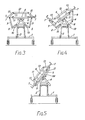
- the side. sections 7 are not hinged directly to the centre section but simply have interengaging features in the form of side frame registers 11 which may be in the form of pins and slots which simply act to steady and hold the centre and side sections engaged in the position shown in Figure 3. It should be noted that when the bed is used as a turning bed the interengaging features 11 disengage as shown in Figure 4.
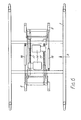
- the side sections 7 are carried by pairs of links 8 and 9 which join the pivot brackets 4 and 5 to the side sections 7 at points underneath the side sections and roughly midway across the side sections (see Figures 1 and 3).
- bottom links 8 are also connected by side frame pivot arms 13 to an end pivot frame 12, at each end of the bed, the pivot frame 12 being rigidly connected to the centre bed section 6.
- the movement of the bottom links 8 is restricted, in a downward direction, by bottom link stops 10.
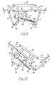
- FIGs 11 and 12 the turning movement of the bed i.e. the movement which enables the patient to be turned when on the bed, can be seen more explicitly.
- an electric turning drive motor 16 which drives a turning actuator screw 25 engaged with a turning trunion nut 26 pivoted on the pivot bracket 4.
- each link 8 may be removed and each link 9 may be connected as shown in Figure 5 by means of a pin to a bracket 9A. This rigidifies the connection between the side sections 7 and the centre section 6 so that when the motor 16 is operated the matress platform comprising centre section 6 and two side sections 7 will tilt naturally as a whole.
- Each link 2 is rigidly connected to an arm 2A pivoted at 2B.
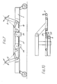
- Each link 2 is moved by an electric motor 14 driving a lifting drive actuator screw 17. The action is assisted by a pair of gas struts 18 which relieve the stress in the motors and screws.
- both motors are operated simultaneously to turn the lifting arms in opposite directions the matress platform will be bodily raised or lowered.
- the mattress platform will longitudinally tilt in one direction or the other.
- the backrest consists of the end portions 7A of the two side sections and the end portions 6A of the centre section of the mattress platform, all of these end portions being pivoted on pivot line 30.
- the centre section 6A can be raised to the position shown in Figure 9 by means of a backrest drive motor 15 supported in a drive bracket 22 attached to the underside of the mattress platform.
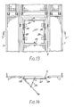
- a hinge flap 27 is provided in the centre of the centre section 6 of the mattress platform. At each side of the flap 27 are pairs of quick release hinge/locating pins. If the pins 28 on one side of the flap are released the other pins 28 on the other side of the flap act as a hinge and the flap can be lowered. With this facility the flap can be lowered from either side of the bed. A flap of this kind is used for toilet purposes etc. The movement of the flap is limited by a stop cable 29 as shown in Figure 14.
Abstract
Description
- This invention relates to a multi-position bed such as is used in hospitals and for persons who by reason of physical disability or age are unable to turn or move themselves in bed. Moving such persons manually at frequent intervals is a time consuming and physically tiring activity for the nurse and hence multi position beds ,have been produced which have the facility for turning a patient and also for tilting in various directions.
- An object of the present invention is to provide a multi position bed which has many different functions but is compact and simple to operate.
- According to the invention a multi-position bed comprises a base frame carrying a mattress platform which is pivoted at its ends, on pivot brackets carried on a base frame, for lateral tilting, the platform comprising a centre section and two side sections, the side sections being connected at their ends by links to end pivot frames on the centre section and being connected at intermediate points through pairs of links to a pivot bracket whereby lateral tilting of the centre section in either direction causes a side section to tilt in the other direction to produce a turning effect on a patient.
- Preferably the side sections and centre sections have interengaging features along their adjacent edges which only engage when the centre section is in its non (laterally) tilted position, but automatically disengage when lateral tilting of the centre section takes place. Preferably the pairs of links are easily disconnectable and one link cf each pair may then be used as a strut to rigidity the connection between each side section and the centre section so that when the centre section is laterally tilted it carries with it both of the side sections so that all three sections remain planar and tilt together.
- preferably the lateral tilting movement of the centre section is produced by a screw and nut mechanism. The screw may be driven by an electric motor carried on the underside of the centre section and the nut may be mounted on one of the pivot brackets.
- From another aspect a multi position bed comprises a base frame on which is pivoted a mattress platformfor lateral tilting movement, the mattress platform comprising a cross section and two side sections, the centre section being pivoted on pivot brackets below the mattress platform and the side sections being connected to the pivot bracket by links, the arrangement being such that with the links in place when the centre section is pivoted laterally in either direction the side section separates and pivots in the other direction so as to produce a turning movement of the patient, the links being disconnectable and the side and centre sections being capable of being rigidified so that when the centre section is tilted the bed frame as a whole tilts laterally without any separation of the side sections.
- Preferably at one end of the bed the centre and side sections both have pivoted end portions which may be raised together to provide an uplifting backrest.
- The side sections and centre sections are preferably separately pivoted but so arranged that, when the centre section is liftedilaterally projecting lifting plates on the centre section will engage corresponding laterally projecting lifting plates on the side sections so that all three sections lift together. When the bed is used in its turning mode the side sections separate from the centre section because the lifting plates are not attached tc each other.
- Preferably the pivot brackets on which the centre section is pivoted are themselves carried by lifting arms at each end of the bed, the arms being pivoted on the mattress platform. These arms may be operated by screw jacks in turn cperated by electric motors so that the mattress platform may be raised and lowered bodily or maybe tilted longitudinally at will.
- Preferably the lifting arms are operable by nut and screw mechanisms, there being two such mechanisms each operated by an electric motor so as to provide independent movement of the arms to enable the bed to be tilted.
- The movement of these arms may be assisted by gas struts so as to relieve the load on the motors and the gas struts may be located longitudinally on or beneath the base frame.
- The base frame may be carried on caster wheels in conventional manner and the caster wheels may have braking facilities.
- The centre section of the mattress platform may have a hinged flap, for toilet purposes, and the flap may have combined hinges and catches at each side so that removal of the catches at one side enables the flap to be pivoted about its other side and vice versa. This enables the flap to be opened from either side of the bed at will.
- In the accompanying drawings:-
- Fig. 1 is a plan view of a bed incorporating the present invention showing bed centre and side sections, cut away to show a linkage system;
- Fig. 2 is a side elevation of the bed showing lifting motors, backrest lifting drive, and bed turning drive;
- Iig. 3 is a view in direction of Arrow B with the bed horizontal, showing linkage system between the bed centre section and the bed side sections;
- Fig. 4 is a view in direction of Arrow B with the bed turned to an angle of 35°, showing positions of the bed side sections and the linkage system;
- Fig. 5 is a view in direction of Arrow B with the bed turned to an angle of 50°, showing positions of the bed side sections, and attachment of top links to lock the side sections to the bed centre section;
- Fig. 6 is a plan view of a base assembly in the direction of Arrow C, showing lifting motors and actuating screws, together with gas filled struts;
- Fig. 7 is a side elevation of the base assembly in direction of Arrow D, cut away to show lifting motors and actuating screws together with the position of the gas filled struts;
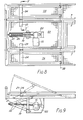
- Fig. 8 is a plan view of the bed showing hinged backrest sections, cut away to show the backrest drive motor, actuating screw, and scissor type lifting linkage;
- Fig. 9 is a side elevation of the hinged backrest showing the backrest drive motor, actuating screw, and scissor type lifting linkage;
- Fig. 10 is a section of 'E'-'E' showing lifting plates attached to the centre section and side sections of the hinged backrest;
- Fig. 11 is a view in direction of Arrow B with the bed horizontal, showing a turn drive motor, actuating screw, and position of linkage system;
- Fig. 12 is a view in direction of Arrow B with the bed turned to an angle of 35°, showing position of the turn drive motor, actuating screw, and linkage system;
- Fig. 13 is a plan view of bed in the direction of Arrow A, showing hinged flap which allows bed pan to be positioned from the underside of the bed frame; and
- Fig. 14 is a section on 'F'-'F' showing the hinged flap which can be hinged down from either side of the bed.
- As shown in Figures 1 to 5 of the drawings the bed comprises a base frame 1 supported on casters and having a pair of pivoted
angled lifting arms 2. One of the pair of lifting arms is pivoted in turn to an interlink 3 pivoted to apivot bracket 4. Theother lifting arm 2 is pivoted directly to a pivot 5. - The
pivot brackets 4 and 5 (best seen in Figures 3 and 4) act as the pivot supports for thecentre section 6 of a mattress platform which is (as seen best in Figure 1) also comprises twoside sections 7. The side.sections 7 are not hinged directly to the centre section but simply have interengaging features in the form ofside frame registers 11 which may be in the form of pins and slots which simply act to steady and hold the centre and side sections engaged in the position shown in Figure 3. It should be noted that when the bed is used as a turning bed theinterengaging features 11 disengage as shown in Figure 4. - The
side sections 7 are carried by pairs oflinks pivot brackets 4 and 5 to theside sections 7 at points underneath the side sections and roughly midway across the side sections (see Figures 1 and 3). - These side sections are also connected by side
frame pivot arms 13 to anend pivot frame 12, at each end of the bed, thepivot frame 12 being rigidly connected to thecentre bed section 6. The movement of thebottom links 8 is restricted, in a downward direction, by bottom link stops 10. - In Figures 11 and 12 the turning movement of the bed i.e. the movement which enables the patient to be turned when on the bed, can be seen more explicitly. In Figure 11 is shown an electric
turning drive motor 16 which drives a turningactuator screw 25 engaged with aturning trunion nut 26 pivoted on thepivot bracket 4. - Operation of the motor in one direction will cause the
centre section 6 to turn about its pivot producing lateral tilting action of the centre section and this will cause theside section 7 to move from the position shown in the Figure 11 to that shown in Figure 12. It will be seen that the interengaging features have been separated and the side section is now tilted at an angle opposite to that at which the centre section is retained in this position by thelinks links - Operations of the
motor 16 in the opposite direction will cause tilting of theframe 6 in the opposite direction and will cause the other side section to separate from the centre section thus producing a turning effect on the patient in the opposite direction. - Reverting to Figures 4 and 5, if a pure tilting movement of the mattress platform as a whole is required then each
link 8 may be removed and eachlink 9 may be connected as shown in Figure 5 by means of a pin to abracket 9A. This rigidifies the connection between theside sections 7 and thecentre section 6 so that when themotor 16 is operated the matress platform comprisingcentre section 6 and twoside sections 7 will tilt naturally as a whole. - The raising and lowering of the mattress platform and longitudinal tilting of the mattress platform is effected by the lifting
arms 2 as shown in enlarged detail in Figures 6 and 7. Eachlink 2 is rigidly connected to an arm 2A pivoted at 2B. Eachlink 2 is moved by anelectric motor 14 driving a liftingdrive actuator screw 17. The action is assisted by a pair ofgas struts 18 which relieve the stress in the motors and screws. - If both motors are operated simultaneously to turn the lifting arms in opposite directions the matress platform will be bodily raised or lowered.
- If the
motors 14 are operated so as to turn thearms 2 in the same direction the mattress platform will longitudinally tilt in one direction or the other. - Alternatively if one of the
motors 14 is operated so as to turn one of thearms 2 whilst theother arm 2 remains stationery, the mattress platform will longitudinally tilt in one direction or the other. - As shown in Figures 8, 9 and 10 there is provision for raising a backrest. The backrest consists of the
end portions 7A of the two side sections and theend portions 6A of the centre section of the mattress platform, all of these end portions being pivoted onpivot line 30. Thecentre section 6A can be raised to the position shown in Figure 9 by means of abackrest drive motor 15 supported in adrive bracket 22 attached to the underside of the mattress platform. Thedrive motor 15, through abackrest actuator screw 19 andtrunion nut 21, operates a pair oflifting links 20 which lift thecentre section 6A to the position shown in Figure 9 or any intermediate position. - As the centre section lifts it carries with it the two side sections. This is achieved by a pair of
plates lower plate 23 on thecentre sections 6A engages beneath theupper plate 24 on thesection 7A. This method of ensuring that the three sections are raised and lowered together does not interfere with the turning action of the bed when the side sections and centre sections of the bed separate. - Turning now to Figures 13 and 14, a
hinge flap 27 is provided in the centre of thecentre section 6 of the mattress platform. At each side of theflap 27 are pairs of quick release hinge/locating pins. If thepins 28 on one side of the flap are released theother pins 28 on the other side of the flap act as a hinge and the flap can be lowered. With this facility the flap can be lowered from either side of the bed. A flap of this kind is used for toilet purposes etc. The movement of the flap is limited by astop cable 29 as shown in Figure 14.
Claims (13)
Priority Applications (1)
| Application Number | Priority Date | Filing Date | Title |
|---|---|---|---|
| AT85307488T ATE59770T1 (en) | 1984-11-20 | 1985-10-17 | MULTIPLE POSITION BED. |
Applications Claiming Priority (2)
| Application Number | Priority Date | Filing Date | Title |
|---|---|---|---|
| GB08429324A GB2167289B (en) | 1984-11-20 | 1984-11-20 | Multi-position bed |
| GB8429324 | 1984-11-20 |
Publications (3)
| Publication Number | Publication Date |
|---|---|
| EP0183371A2 true EP0183371A2 (en) | 1986-06-04 |
| EP0183371A3 EP0183371A3 (en) | 1987-09-30 |
| EP0183371B1 EP0183371B1 (en) | 1991-01-09 |
Family
ID=10570008
Family Applications (1)
| Application Number | Title | Priority Date | Filing Date |
|---|---|---|---|
| EP85307488A Expired - Lifetime EP0183371B1 (en) | 1984-11-20 | 1985-10-17 | Multi-position bed |
Country Status (8)
| Country | Link |
|---|---|
| US (1) | US4658450A (en) |
| EP (1) | EP0183371B1 (en) |
| JP (1) | JPS61128969A (en) |
| AT (1) | ATE59770T1 (en) |
| CA (1) | CA1247805A (en) |
| DE (1) | DE3581273D1 (en) |
| ES (1) | ES8800592A1 (en) |
| GB (1) | GB2167289B (en) |
Cited By (4)
| Publication number | Priority date | Publication date | Assignee | Title |
|---|---|---|---|---|
| GB2205232A (en) * | 1987-05-28 | 1988-12-07 | Egerton Hospital Equip | Bed with hinged panel safety feature |
| EP0363541A1 (en) * | 1988-10-13 | 1990-04-18 | Tuneo Yamamoto | An automatic caring system for bed-ridden patients |
| WO1999062455A1 (en) * | 1998-06-04 | 1999-12-09 | Andre Viljoen | Therapeutic bed |
| EP2716269A1 (en) * | 2012-10-05 | 2014-04-09 | K.R. Hospitalsudstyr A/S | A longitudinally tiltable bed |
Families Citing this family (60)
| Publication number | Priority date | Publication date | Assignee | Title |
|---|---|---|---|---|
| US5479665A (en) * | 1983-09-09 | 1996-01-02 | Cassidy; Joseph P. | Automated tri-fold bed |
| US4805249A (en) * | 1986-09-19 | 1989-02-21 | Pulukadang Freddy Usman | Rehabilitation bed |
| JPS63257561A (en) * | 1987-04-16 | 1988-10-25 | 株式会社日本エム・ディ・エム | Shaking bed |
| IE60532B1 (en) * | 1987-11-02 | 1994-07-27 | Ethos Medical Research Limited | A therapeutic bed |
| US5802640A (en) | 1992-04-03 | 1998-09-08 | Hill-Rom, Inc. | Patient care system |
| US5181288A (en) * | 1989-05-30 | 1993-01-26 | The Mediscus Group Inc. | Therapeutic turning bed |
| US4934007A (en) * | 1989-07-20 | 1990-06-19 | Metal Craft Manufacturing Ltd. | Deck tilting device |
| JPH0370559A (en) * | 1989-08-09 | 1991-03-26 | Gijutsu Kenkyu Kumiai Iryo Fukushi Kiki Kenkyusho | Mechanism for supporting floor of bed |
| US4995067A (en) * | 1989-10-05 | 1991-02-19 | The United States Of America As Represented By The Secretary Of The Air Force | Surgical and x-ray operation table extension |
| JPH03128009A (en) * | 1989-10-13 | 1991-05-31 | Paramaunto Bed Kk | Elevating type side fence of bed or the like |
| JPH03128010A (en) * | 1989-10-13 | 1991-05-31 | Paramaunto Bed Kk | Elevating type side fence of bed or the like |
| US5317769A (en) * | 1992-11-10 | 1994-06-07 | Hill-Rom Company, Inc. | Hospital bed |
| GB2272367B (en) * | 1992-11-16 | 1996-01-31 | Hung Yung Feng | A multi-function and automatic sick bed |
| US5392479A (en) * | 1994-01-28 | 1995-02-28 | Liao; Yu-Kuen | Multipurpose sickbed |
| US5640729A (en) * | 1994-03-03 | 1997-06-24 | Marino; Mario Hector Silvio | Ergonomic mechanism for use in hospitals |
| US5500964A (en) * | 1994-03-09 | 1996-03-26 | National Health Equipment, Inc. | Patient manipulating kit and method of converting a hospital bed to a patient manipulation apparatus |
| JP2987290B2 (en) * | 1994-05-02 | 1999-12-06 | フランスベッド株式会社 | Bed equipment |
| US5699566A (en) * | 1996-06-07 | 1997-12-23 | Chuang; Ching-Shan | Sickbed |
| WO1999007320A2 (en) | 1997-08-08 | 1999-02-18 | Hill-Rom, Inc. | Proning bed |
| AU4836499A (en) | 1998-06-26 | 2000-01-17 | Jack J. Brooks | Proning bed |
| US6212712B1 (en) | 1999-04-20 | 2001-04-10 | Richard Hardy Topp | Mobile stretcher with lateral recumbant mechanism |
| JP2003521964A (en) * | 1999-04-21 | 2003-07-22 | ヒル−ロム サービシーズ,インコーポレイティド | Prone bed |
| AUPQ013799A0 (en) * | 1999-05-04 | 1999-05-27 | Donjac Pty. Ltd. | Support assembly means |
| EP2327385B1 (en) * | 1999-12-29 | 2016-03-16 | Hill-Rom Services, Inc. | Patient support with barrier |
| AU2001245792A1 (en) * | 2000-03-17 | 2001-10-03 | Hill-Rom, Inc. | Proning bed |
| US6817363B2 (en) * | 2000-07-14 | 2004-11-16 | Hill-Rom Services, Inc. | Pulmonary therapy apparatus |
| CA2337994C (en) * | 2001-02-26 | 2011-07-05 | Probed Medical Technologies Inc. | Bed with adjustable positions |
| AU2003296924A1 (en) * | 2002-07-24 | 2004-04-30 | France Bed Co., Ltd. | Tilting bed apparatus and mattress |
| US7073219B2 (en) | 2004-01-06 | 2006-07-11 | Teknion Concept | Side rail, hospital bed including the same, method of operating associated thereto and kit for assembling the side rail |
| EP1552772A1 (en) | 2004-01-06 | 2005-07-13 | Teknion Concept | Side Rail, hospital bed including the same, method of operating associated thereto and kit for assembling the side rail |
| US20050262635A1 (en) * | 2004-05-28 | 2005-12-01 | Wing Thomas W | Tilt bed |
| EP1604628A3 (en) * | 2004-06-11 | 2006-07-19 | Hill-Rom Services, Inc. | Hospital bed for the treatment of pulmonary diseases and nosocomial pressure ulcers |
| US7757318B2 (en) | 2004-09-13 | 2010-07-20 | Kreg Therapeutics, Inc. | Mattress for a hospital bed |
| US7676862B2 (en) | 2004-09-13 | 2010-03-16 | Kreg Medical, Inc. | Siderail for hospital bed |
| US7779494B2 (en) | 2004-09-13 | 2010-08-24 | Kreg Therapeutics, Inc. | Bed having fixed length foot deck |
| US7743441B2 (en) | 2004-09-13 | 2010-06-29 | Kreg Therapeutics, Inc. | Expandable width bed |
| US7913337B1 (en) | 2005-05-31 | 2011-03-29 | Masson Marcos V | Ambulatory surgical gurney |
| US7716761B1 (en) * | 2005-07-06 | 2010-05-18 | Gilstad Dennis W | Adaptive positioning system |
| EP1957024A4 (en) * | 2005-12-05 | 2009-05-13 | Scott M Ahlman | Patient single surface system |
| US7761942B2 (en) | 2007-10-09 | 2010-07-27 | Bedlab, Llc | Bed with adjustable patient support framework |
| US7716762B2 (en) | 2007-10-14 | 2010-05-18 | Bedlab, Llc | Bed with sacral and trochanter pressure relieve functions |
| US7886379B2 (en) | 2007-10-14 | 2011-02-15 | Bedlab, Llc | Support surface that modulates to cradle a patient's midsection |
| US20090094745A1 (en) * | 2007-10-14 | 2009-04-16 | Eduardo Rene Benzo | Modulating Support Surface to Aid Patient Entry and Exit |
| WO2009158018A1 (en) | 2008-06-27 | 2009-12-30 | Kreg Medical, Inc. | Bed with modified foot deck |
| US7971297B2 (en) | 2009-06-17 | 2011-07-05 | Masson Marcos V | Slidable cushion for a multi-purpose gurney |
| US7730565B1 (en) | 2009-06-17 | 2010-06-08 | Masson Marcos V | Anaconda for a multi-purpose gurney |
| KR101150875B1 (en) * | 2010-03-04 | 2012-06-13 | 계명대학교 산학협력단 | Functional table for patient transportation |
| WO2011144767A1 (en) * | 2010-05-18 | 2011-11-24 | Industrias Tobia, S.A. | Intelligent hospital bed and method for operating same |
| CN202146292U (en) | 2011-07-15 | 2012-02-22 | 中山大学中山眼科中心 | Deformable bed for ophthalmologic examination of children |
| US9498397B2 (en) | 2012-04-16 | 2016-11-22 | Allen Medical Systems, Inc. | Dual column surgical support system |
| US9724254B2 (en) | 2014-10-03 | 2017-08-08 | Daryl L. Cole | Adjustable bed |
| US10492973B2 (en) | 2015-01-05 | 2019-12-03 | Allen Medical Systems, Inc. | Dual modality prone spine patient support apparatuses |
| US9655793B2 (en) | 2015-04-09 | 2017-05-23 | Allen Medical Systems, Inc. | Brake release mechanism for surgical table |
| US10363189B2 (en) | 2015-10-23 | 2019-07-30 | Allen Medical Systems, Inc. | Surgical patient support for accommodating lateral-to-prone patient positioning |
| US10561559B2 (en) | 2015-10-23 | 2020-02-18 | Allen Medical Systems, Inc. | Surgical patient support system and method for lateral-to-prone support of a patient during spine surgery |
| US10857054B2 (en) | 2015-11-13 | 2020-12-08 | Allen Medical Systems, Inc. | Person support apparatuses for subject repositioning |
| US11213448B2 (en) | 2017-07-31 | 2022-01-04 | Allen Medical Systems, Inc. | Rotation lockout for surgical support |
| TWM559120U (en) * | 2018-02-01 | 2018-05-01 | Ulife Healthcare Inc | Electric furniture bed |
| US11202731B2 (en) | 2018-02-28 | 2021-12-21 | Allen Medical Systems, Inc. | Surgical patient support and methods thereof |
| US11471354B2 (en) | 2018-08-30 | 2022-10-18 | Allen Medical Systems, Inc. | Patient support with selectable pivot |
Citations (6)
| Publication number | Priority date | Publication date | Assignee | Title |
|---|---|---|---|---|
| DE869C (en) * | 1877-10-08 | A. BRÜNING, Schlossermeister, in Berlin | Sickbed with bedside chair | |
| US3608102A (en) * | 1969-06-27 | 1971-09-28 | Robert Goodman | Hospital bed |
| DE2049254A1 (en) * | 1970-10-07 | 1971-12-16 | Joh Stiegelmeyer & Co GmbH, 4900 Herford | Sickbed |
| US3739406A (en) * | 1970-09-16 | 1973-06-19 | Stiegelmeyer & Co Gmbh | Adjustable bed |
| US4345344A (en) * | 1980-04-08 | 1982-08-24 | Centre De Recherche Industrielle Du Quebec | Hospital bed |
| DE8304560U1 (en) * | 1983-02-18 | 1983-06-09 | Ciecierski, Wolf, 8403 Bad Abbach | Adjustable lounger |
Family Cites Families (12)
| Publication number | Priority date | Publication date | Assignee | Title |
|---|---|---|---|---|
| US577303A (en) * | 1897-02-16 | Invalid-bed | ||
| US684218A (en) * | 1901-04-26 | 1901-10-08 | Richard hennessy | Invalid-bedstead. |
| US954082A (en) * | 1909-09-03 | 1910-04-05 | Michael D Gavan | Invalid-bed. |
| US1677218A (en) * | 1926-04-28 | 1928-07-17 | Shand George | Bed |
| US2284470A (en) * | 1941-03-20 | 1942-05-26 | American Sterilizer Co | Labor or similar bed |
| US2522018A (en) * | 1948-11-06 | 1950-09-12 | Norman S Blackman | Bed |
| US3200416A (en) * | 1963-12-04 | 1965-08-17 | Arthur M Warrick | Invalid bed |
| AU1331476A (en) * | 1975-05-01 | 1977-10-27 | Betsone Ind Ltd | Turning bed |
| US4084274A (en) * | 1975-05-01 | 1978-04-18 | Betstone Industries Limited | Turning bed |
| SE428526B (en) * | 1979-12-04 | 1983-07-11 | Landstingens Inkopscentral | BED-BOTTOM DEVICE DIVIDED INTO A LONG-TERM MIDDLE AND TWO LONG-TERM SIDE PARTS |
| JPS5725221A (en) * | 1980-07-21 | 1982-02-10 | Ageo Seimitsu Kk | Production of hand for watch |
| US4425673A (en) * | 1980-12-01 | 1984-01-17 | B-W Health Products, Inc. | Lifting system for adjustable hospital bed |
-
1984
- 1984-11-20 GB GB08429324A patent/GB2167289B/en not_active Expired
-
1985
- 1985-10-17 DE DE8585307488T patent/DE3581273D1/en not_active Expired - Lifetime
- 1985-10-17 AT AT85307488T patent/ATE59770T1/en not_active IP Right Cessation
- 1985-10-17 EP EP85307488A patent/EP0183371B1/en not_active Expired - Lifetime
- 1985-10-29 CA CA000494088A patent/CA1247805A/en not_active Expired
- 1985-11-13 US US06/797,804 patent/US4658450A/en not_active Expired - Fee Related
- 1985-11-15 JP JP60255165A patent/JPS61128969A/en active Granted
- 1985-11-19 ES ES549046A patent/ES8800592A1/en not_active Expired
Patent Citations (6)
| Publication number | Priority date | Publication date | Assignee | Title |
|---|---|---|---|---|
| DE869C (en) * | 1877-10-08 | A. BRÜNING, Schlossermeister, in Berlin | Sickbed with bedside chair | |
| US3608102A (en) * | 1969-06-27 | 1971-09-28 | Robert Goodman | Hospital bed |
| US3739406A (en) * | 1970-09-16 | 1973-06-19 | Stiegelmeyer & Co Gmbh | Adjustable bed |
| DE2049254A1 (en) * | 1970-10-07 | 1971-12-16 | Joh Stiegelmeyer & Co GmbH, 4900 Herford | Sickbed |
| US4345344A (en) * | 1980-04-08 | 1982-08-24 | Centre De Recherche Industrielle Du Quebec | Hospital bed |
| DE8304560U1 (en) * | 1983-02-18 | 1983-06-09 | Ciecierski, Wolf, 8403 Bad Abbach | Adjustable lounger |
Cited By (8)
| Publication number | Priority date | Publication date | Assignee | Title |
|---|---|---|---|---|
| GB2205232A (en) * | 1987-05-28 | 1988-12-07 | Egerton Hospital Equip | Bed with hinged panel safety feature |
| GB2205232B (en) * | 1987-05-28 | 1991-04-03 | Egerton Hospital Equip | Bed with hinged panel safety feature |
| EP0363541A1 (en) * | 1988-10-13 | 1990-04-18 | Tuneo Yamamoto | An automatic caring system for bed-ridden patients |
| WO1999062455A1 (en) * | 1998-06-04 | 1999-12-09 | Andre Viljoen | Therapeutic bed |
| GB2353703A (en) * | 1998-06-04 | 2001-03-07 | Andre Viljoen | Therapeutic bed |
| GB2353703B (en) * | 1998-06-04 | 2002-01-23 | Andre Viljoen | Therapeutic bed |
| US6502260B2 (en) | 1998-06-04 | 2003-01-07 | Andre Viljoen | Therapeutic bed |
| EP2716269A1 (en) * | 2012-10-05 | 2014-04-09 | K.R. Hospitalsudstyr A/S | A longitudinally tiltable bed |
Also Published As
| Publication number | Publication date |
|---|---|
| EP0183371A3 (en) | 1987-09-30 |
| CA1247805A (en) | 1989-01-03 |
| GB2167289B (en) | 1988-05-05 |
| JPH0374107B2 (en) | 1991-11-25 |
| US4658450A (en) | 1987-04-21 |
| ES549046A0 (en) | 1987-11-16 |
| DE3581273D1 (en) | 1991-02-14 |
| GB8429324D0 (en) | 1984-12-27 |
| GB2167289A (en) | 1986-05-29 |
| JPS61128969A (en) | 1986-06-17 |
| ES8800592A1 (en) | 1987-11-16 |
| ATE59770T1 (en) | 1991-01-15 |
| EP0183371B1 (en) | 1991-01-09 |
Similar Documents
| Publication | Publication Date | Title |
|---|---|---|
| US4658450A (en) | Multi-position bed | |
| EP0329697B1 (en) | Arrangement for a lift adapted to a motor vehicle | |
| US6912746B2 (en) | Bed | |
| CA2492765C (en) | Collapsible siderail assembly | |
| EP1621175B1 (en) | Bed having a chair egress position | |
| PT82522B (en) | HOSPITAL BED | |
| EP2283799B1 (en) | Side and end brake/steer mechanism for stretchers | |
| JP3459267B2 (en) | Accident and emergency transport carts | |
| US4613997A (en) | Vertical access convalescent bed | |
| CA1040550A (en) | Lifting platform | |
| US20120153687A1 (en) | Bed, and combining method and separating method of bed | |
| US7306251B2 (en) | Reclining wheelchair | |
| KR19990071966A (en) | Device for handling incompetent patients | |
| JP2001511047A (en) | Mobile nursing chair | |
| US11806290B2 (en) | Adjustable patient support apparatus for assisted egress and ingress | |
| US7451505B2 (en) | Bed tilting apparatus | |
| US4504988A (en) | Patient transfer arrangement | |
| CN112754794A (en) | Lifting type foldable wheelchair | |
| CN116211611A (en) | Nursing bed is stood up in medical treatment | |
| CN214713094U (en) | Lifting type foldable wheelchair | |
| JP3006428U (en) | Nursing bed | |
| TWI772941B (en) | Bed frame capable of combining wheel chair | |
| JP3418314B2 (en) | Wheelchair simple vehicle | |
| JP2001218797A (en) | Bed for nursing | |
| JPS5951833B2 (en) | betsudo |
Legal Events
| Date | Code | Title | Description |
|---|---|---|---|
| PUAI | Public reference made under article 153(3) epc to a published international application that has entered the european phase |
Free format text: ORIGINAL CODE: 0009012 |
|
| AK | Designated contracting states |
Kind code of ref document: A2 Designated state(s): AT BE CH DE FR GB IT LI LU NL SE |
|
| PUAL | Search report despatched |
Free format text: ORIGINAL CODE: 0009013 |
|
| AK | Designated contracting states |
Kind code of ref document: A3 Designated state(s): AT BE CH DE FR GB IT LI LU NL SE |
|
| 17P | Request for examination filed |
Effective date: 19880316 |
|
| 17Q | First examination report despatched |
Effective date: 19891220 |
|
| GRAA | (expected) grant |
Free format text: ORIGINAL CODE: 0009210 |
|
| AK | Designated contracting states |
Kind code of ref document: B1 Designated state(s): AT BE CH DE FR GB IT LI LU NL SE |
|
| REF | Corresponds to: |
Ref document number: 59770 Country of ref document: AT Date of ref document: 19910115 Kind code of ref document: T |
|
| ITF | It: translation for a ep patent filed |
Owner name: JACOBACCI & PERANI S.P.A. |
|
| ET | Fr: translation filed | ||
| REF | Corresponds to: |
Ref document number: 3581273 Country of ref document: DE Date of ref document: 19910214 |
|
| PLBE | No opposition filed within time limit |
Free format text: ORIGINAL CODE: 0009261 |
|
| STAA | Information on the status of an ep patent application or granted ep patent |
Free format text: STATUS: NO OPPOSITION FILED WITHIN TIME LIMIT |
|
| 26N | No opposition filed | ||
| EPTA | Lu: last paid annual fee | ||
| EAL | Se: european patent in force in sweden |
Ref document number: 85307488.8 |
|
| PGFP | Annual fee paid to national office [announced via postgrant information from national office to epo] |
Ref country code: LU Payment date: 19951101 Year of fee payment: 11 |
|
| PGFP | Annual fee paid to national office [announced via postgrant information from national office to epo] |
Ref country code: GB Payment date: 19951108 Year of fee payment: 11 |
|
| PGFP | Annual fee paid to national office [announced via postgrant information from national office to epo] |
Ref country code: SE Payment date: 19951113 Year of fee payment: 11 |
|
| PGFP | Annual fee paid to national office [announced via postgrant information from national office to epo] |
Ref country code: BE Payment date: 19951116 Year of fee payment: 11 |
|
| PGFP | Annual fee paid to national office [announced via postgrant information from national office to epo] |
Ref country code: FR Payment date: 19951120 Year of fee payment: 11 |
|
| PGFP | Annual fee paid to national office [announced via postgrant information from national office to epo] |
Ref country code: AT Payment date: 19951121 Year of fee payment: 11 |
|
| PGFP | Annual fee paid to national office [announced via postgrant information from national office to epo] |
Ref country code: DE Payment date: 19951123 Year of fee payment: 11 |
|
| PGFP | Annual fee paid to national office [announced via postgrant information from national office to epo] |
Ref country code: CH Payment date: 19951127 Year of fee payment: 11 |
|
| PGFP | Annual fee paid to national office [announced via postgrant information from national office to epo] |
Ref country code: NL Payment date: 19951130 Year of fee payment: 11 |
|
| PG25 | Lapsed in a contracting state [announced via postgrant information from national office to epo] |
Ref country code: LU Free format text: LAPSE BECAUSE OF NON-PAYMENT OF DUE FEES Effective date: 19961017 Ref country code: GB Effective date: 19961017 Ref country code: AT Effective date: 19961017 |
|
| PG25 | Lapsed in a contracting state [announced via postgrant information from national office to epo] |
Ref country code: SE Effective date: 19961018 |
|
| PG25 | Lapsed in a contracting state [announced via postgrant information from national office to epo] |
Ref country code: LI Effective date: 19961031 Ref country code: CH Effective date: 19961031 Ref country code: BE Effective date: 19961031 |
|
| BERE | Be: lapsed |
Owner name: EGERTON HOSPITAL EQUIPMENT LTD Effective date: 19961031 |
|
| PG25 | Lapsed in a contracting state [announced via postgrant information from national office to epo] |
Ref country code: NL Effective date: 19970501 |
|
| GBPC | Gb: european patent ceased through non-payment of renewal fee |
Effective date: 19961017 |
|
| REG | Reference to a national code |
Ref country code: CH Ref legal event code: PL |
|
| PG25 | Lapsed in a contracting state [announced via postgrant information from national office to epo] |
Ref country code: FR Effective date: 19970630 |
|
| NLV4 | Nl: lapsed or anulled due to non-payment of the annual fee |
Effective date: 19970501 |
|
| PG25 | Lapsed in a contracting state [announced via postgrant information from national office to epo] |
Ref country code: DE Effective date: 19970701 |
|
| EUG | Se: european patent has lapsed |
Ref document number: 85307488.8 |
|
| REG | Reference to a national code |
Ref country code: FR Ref legal event code: ST |