EP0182529A2 - Radiographic system - Google Patents
Radiographic system Download PDFInfo
- Publication number
- EP0182529A2 EP0182529A2 EP85307968A EP85307968A EP0182529A2 EP 0182529 A2 EP0182529 A2 EP 0182529A2 EP 85307968 A EP85307968 A EP 85307968A EP 85307968 A EP85307968 A EP 85307968A EP 0182529 A2 EP0182529 A2 EP 0182529A2
- Authority
- EP
- European Patent Office
- Prior art keywords
- detector
- radiation
- source
- ray
- focal spot
- Prior art date
- Legal status (The legal status is an assumption and is not a legal conclusion. Google has not performed a legal analysis and makes no representation as to the accuracy of the status listed.)
- Granted
Links
Images


Classifications
-
- A—HUMAN NECESSITIES
- A61—MEDICAL OR VETERINARY SCIENCE; HYGIENE
- A61B—DIAGNOSIS; SURGERY; IDENTIFICATION
- A61B6/00—Apparatus for radiation diagnosis, e.g. combined with radiation therapy equipment
- A61B6/02—Devices for diagnosis sequentially in different planes; Stereoscopic radiation diagnosis
- A61B6/03—Computerised tomographs
- A61B6/032—Transmission computed tomography [CT]
-
- A—HUMAN NECESSITIES
- A61—MEDICAL OR VETERINARY SCIENCE; HYGIENE
- A61B—DIAGNOSIS; SURGERY; IDENTIFICATION
- A61B6/00—Apparatus for radiation diagnosis, e.g. combined with radiation therapy equipment
- A61B6/40—Apparatus for radiation diagnosis, e.g. combined with radiation therapy equipment with arrangements for generating radiation specially adapted for radiation diagnosis
- A61B6/4064—Apparatus for radiation diagnosis, e.g. combined with radiation therapy equipment with arrangements for generating radiation specially adapted for radiation diagnosis specially adapted for producing a particular type of beam
- A61B6/4085—Cone-beams
-
- A—HUMAN NECESSITIES
- A61—MEDICAL OR VETERINARY SCIENCE; HYGIENE
- A61B—DIAGNOSIS; SURGERY; IDENTIFICATION
- A61B6/00—Apparatus for radiation diagnosis, e.g. combined with radiation therapy equipment
- A61B6/42—Apparatus for radiation diagnosis, e.g. combined with radiation therapy equipment with arrangements for detecting radiation specially adapted for radiation diagnosis
- A61B6/4208—Apparatus for radiation diagnosis, e.g. combined with radiation therapy equipment with arrangements for detecting radiation specially adapted for radiation diagnosis characterised by using a particular type of detector
- A61B6/4241—Apparatus for radiation diagnosis, e.g. combined with radiation therapy equipment with arrangements for detecting radiation specially adapted for radiation diagnosis characterised by using a particular type of detector using energy resolving detectors, e.g. photon counting
-
- A—HUMAN NECESSITIES
- A61—MEDICAL OR VETERINARY SCIENCE; HYGIENE
- A61B—DIAGNOSIS; SURGERY; IDENTIFICATION
- A61B6/00—Apparatus for radiation diagnosis, e.g. combined with radiation therapy equipment
- A61B6/48—Diagnostic techniques
- A61B6/482—Diagnostic techniques involving multiple energy imaging
-
- G—PHYSICS
- G01—MEASURING; TESTING
- G01T—MEASUREMENT OF NUCLEAR OR X-RADIATION
- G01T1/00—Measuring X-radiation, gamma radiation, corpuscular radiation, or cosmic radiation
- G01T1/16—Measuring radiation intensity
- G01T1/161—Applications in the field of nuclear medicine, e.g. in vivo counting
- G01T1/164—Scintigraphy
- G01T1/1641—Static instruments for imaging the distribution of radioactivity in one or two dimensions using one or several scintillating elements; Radio-isotope cameras
- G01T1/1644—Static instruments for imaging the distribution of radioactivity in one or two dimensions using one or several scintillating elements; Radio-isotope cameras using an array of optically separate scintillation elements permitting direct location of scintillations
-
- G—PHYSICS
- G01—MEASURING; TESTING
- G01T—MEASUREMENT OF NUCLEAR OR X-RADIATION
- G01T1/00—Measuring X-radiation, gamma radiation, corpuscular radiation, or cosmic radiation
- G01T1/16—Measuring radiation intensity
- G01T1/20—Measuring radiation intensity with scintillation detectors
- G01T1/2018—Scintillation-photodiode combinations
- G01T1/20181—Stacked detectors, e.g. for measuring energy and positional information
-
- G—PHYSICS
- G01—MEASURING; TESTING
- G01T—MEASUREMENT OF NUCLEAR OR X-RADIATION
- G01T1/00—Measuring X-radiation, gamma radiation, corpuscular radiation, or cosmic radiation
- G01T1/16—Measuring radiation intensity
- G01T1/20—Measuring radiation intensity with scintillation detectors
- G01T1/2018—Scintillation-photodiode combinations
- G01T1/20182—Modular detectors, e.g. tiled scintillators or tiled photodiodes
-
- G—PHYSICS
- G01—MEASURING; TESTING
- G01T—MEASUREMENT OF NUCLEAR OR X-RADIATION
- G01T1/00—Measuring X-radiation, gamma radiation, corpuscular radiation, or cosmic radiation
- G01T1/16—Measuring radiation intensity
- G01T1/20—Measuring radiation intensity with scintillation detectors
- G01T1/202—Measuring radiation intensity with scintillation detectors the detector being a crystal
-
- A—HUMAN NECESSITIES
- A61—MEDICAL OR VETERINARY SCIENCE; HYGIENE
- A61B—DIAGNOSIS; SURGERY; IDENTIFICATION
- A61B6/00—Apparatus for radiation diagnosis, e.g. combined with radiation therapy equipment
- A61B6/40—Apparatus for radiation diagnosis, e.g. combined with radiation therapy equipment with arrangements for generating radiation specially adapted for radiation diagnosis
- A61B6/4021—Apparatus for radiation diagnosis, e.g. combined with radiation therapy equipment with arrangements for generating radiation specially adapted for radiation diagnosis involving movement of the focal spot
Definitions
- This invention relates generally to the field of radiographic systems.
- Radiography is a long known medical diagnostic imaging technique.
- an x-ray source is actuated to direct a divergent area beam of x-rays through a patient.
- a cassette containing an x-ray sensitive phosphor screen and light and x-ray sensitive film is positioned in the x-ray beam on the side of the patient opposite the source. X-radiation passing through the patient's body is thereby attenuated in various degrees to produce on the film a shadow image of a portion of the patient through which the x-rays pass.
- digital radiographic techniques and systems have been developed.
- the source directs x-radiation through a patient's body to a detector assembly located in the beam path beyond the patient.
- the detector produces electrical signals defining the radiation pattern emergent from the patient and incident on the assembly. These signals are then processed to yield a visual display of the image.
- the detector assembly includes an elongated planar array of individual detector elements.
- a detector element can suitably comprise a scintillator having a receiving face positioned in front of a photodiode. Each detector element responds to incident x-radiation to produce an analog electrical charge signal indicative of such radiation. These analog electrical signals represent the radiation pattern emergent from the patient's body.
- the analog signals are sampled and processed by imaging circuitry, primarily to improve their signal to noise ratio, and are subsequently digitized.
- the digital signals are fed to a digital data processing unit.
- the data processing unit records and/or processes and enhances the digital data.
- a display unit responds to appropriate digital data representing the image to convert the digital information back into analog form and to produce a visual display of the patient's internal body structure derived from the acquired image pattern of radiation.
- the display unit can be coupled directly to the digital data processing unit for substantially real time imaging, or can be fed stored digital data from digital storage means such as tapes or disks, representing patient images produced from earlier studies.
- Digital radiography includes techniques in which a thin spread beam of x-radiation is used.
- SPR scan projection radiography
- the spread beam is scanned across the patient, or the patient is movably interposed between the spread beam x-ray source and the detector assembly, the detector being maintained in continuous alignment with the beam.
- the relative movement effected between the source-detector arrangement and the patient's body scans a large portion of the body.
- Discrete element detectors have been proposed comprising a single line of detectdor elements.
- Other proposals have included planar rectangular detector arrays of square detector elements.
- the detector array comprises a planar rectangular array of square detector elements, to improve the signal to noise ratio of the information developed by the detector, by the use of time delay and integrate (TDI) circuitry.
- TDI time delay and integrate
- An embodiment of such a proposed system is described in United States Letters Patent No. 4,383,327, issued on May 10, 1983 to Kruger, which is hereby incorporated by reference.
- Such proposed TDI systems employ sampling at regular intervals of detector motion, and motion- synchronous shifting and adding of the individual detector-produced analog charge signals which are sampled.
- subtraction An important technique for enhancing a digitally represented image is called “subtraction”. There are two types of subtraction techniques, one being “temporal” subtraction, the other being “energy” subtraction.
- Temporal, sometimes called "mask mode” subtraction is a technique that can be used to remove overlying and underlying structures from an image when the object of interest is enhanced by a radiopaque contrast agent. Images are acquired with and withoutthe contrast agent present and the data representing the former image is subtracted from the data representing the latter, substantially cancelling out all but the blood vessels or anatomical regions containing the contrast agent.
- a principal limitation of digital temporal subtraction is the susceptibility to misregistration, or "motion artifacts" caused by patient movement between the acquisition of the images with and without the contrast agent.
- temporal subtraction which is less susceptible to motion artifacts
- energy subtraction exploits energy-related differences in attenuation properties of various types of tissues, such as the difference of the attenuation characteristics of soft tissue and bone.
- Soft tissue shows less change in attenuation capability with respect to energy than does bone.
- Energy subtraction has the advantage, relative to temporal subtraction, of being substantially not subject to motion artifacts resulting from the patient's movement between exposures.
- the time separating the lower and higher imaging acquisitions is quite short, often less than one sixtieth of a second.
- a dual layer planar dual energy radiation detector assembly has been suggested.
- a first layer comprises a rectangular planar array of square detector photodiode elements including a first radiation sensitive scintillation material overlying the photodiodes and being selected for its primary response to radiation of a lower energy range.
- a second planar layer is located, or "stacked", directly behind the first layer, with respect to the x-ray tube, and comprises a similar rectangular array of detector elements congruent and aligned with the first layer.
- the second layer includes a second radiation sensitive scintillation material selected for its propensity to respond primarily to radiation of a higher energy level, which has passed through the first layer substantially without being detected.
- Such a dual energy detector structure when used in conjunction with an x-ray tube emitting energy over a wide range, will provide data describing two separate images, i.e. one an image of lower energy x-radiation passing through the subject, the other being an image describing the pattern of higher energy radiation.
- a flat rectangular detector of any type has the inherent disadvantage that radiation intensity falling upon the various detector elements is a function of the element's relative position in the array, in addition to being a function of the patient's body structure. This results from the fact that x-ray energy travelling from the x-ray tube focal spot toward a detector element near the image periphery must travel a longer path than x-ray energy directed toward the central portion of the detector. This disadvantage is a problem in both single and dual energy flat detector systems
- x-rays incident on centrally located detector elements enter the scintillator nearly normal to the receiving face.
- Rays incident on peripherally located elements enter the scintillators at angles which vary considerably from the normal.
- a ray entering a peripheral element travels a longer path within its respective scintillator than does a ray entering central elements. Due to the longer paths travelled, a ray entering a peripheral element produces a greater scintillation than does a ray of equal value entering a central element, causing a response by the peripheral element that falsely exaggerates the indicated energy of the ray entering the peripheral element.
- This problem acquires yet another aspect where a dual energy detector is used having two sets of "stacked" detector element arrays.
- a greater proportion of a ray's energy is dissipated in passage through a peripheral element than in passage through a central element. Therefore, a smaller fraction of energy incident on a peripheral front layer detector element is left to actuate a rear peripheral detector element than would be left to actuate a rear central detector after passage through a front central element. This phenomenon distorts the relative responses of the dual energy detector arrays, or layers, in a way which is very difficult to correct.
- Such a radiographic system includes an x-ray source and a detector assembly maintained in a spaced relationship to define a subject examination space therebetween.
- the detector assembly includes a plurality of individual detector elements each having a radiation sensitive face.
- the radiation sensitive faces of the individual detector elements collectively generally define a concave curved surface oriented toward the x-ray tube.
- the system further includes operating power means for actuating the tube to propagate x-rays toward the detector and through the subject examiantion space.
- Imaging circuitry coupled to the detector elements processes data from the detector elements to form a representation of an image of internal structure of a subject when located at the subject examination space.
- the curved surface collectively defined by the detector element faces increases uniformity of response of the detector with respect to element position by reducing differences in the lengths of the x-ray paths from the tube to the respective detector elements.
- the curved surface also substantially eliminates differences in the lengths of the x-ray paths in the detector itself, which also increases uniformity of response.
- the concavity of the detector configuration substantially eliminates any parallax effect which is typically suffered by flat split energy detector arrays.
- the x-ray tube defines a focal spot or neighbourhood from which most of its x-radiation emanates, and the detector concave curvature defines approximately a portion of a cylinder whose axis intersects the focal spot.
- the use of the partial cylindrical detector surface configuration equalises the x-ray path from the tube to each row of detector elements.
- the surface defined by the collective detector element faces approximates a portion of a sphere having its centre lcoated substantially coincident with the focal spot.
- the use of the spherical concave detector surface further improves upon the uniformity of detector response by locating every detector element substantially equi-distant from the x-ray tube focal spot.
- means is provided to scan the detector assembly relative to a subject located in the examination space, and the detector elements are adapted to respond to incident radiation to produce analogue electrical charge signals indicative of the radiation.
- the imaging circuitry comprises time delay and integrate circuitry to shift and add the electrical charge signals along rows of detector elements in synchronism with detector scanning motion. The use of the time delay and integrate circuitry in this embodiment enhances the signal-to-noise ratio of data represented by the electrical charge signals, and improves the quality of the final image so produced from that data.
- An important aspect of this invention is the incorporation of focussed detector arrangements in medical imaging systems.
- a system S for performing digital scan projection radiography is illustrated in general form in Figure 1.
- the system S directs a pattern of x-rays through a patient P and produces, from information borne by the x-ray pattern emergent from the patient's body, a representation, generally in the form of a visible image, describing internal structure or condition of the patient's body.
- the system S incorporates an x-ray source 10 for directing a beam of x-ray energy illustrated as a collection of rays 12 through the patient P and onto a detector assembly 14.
- a first collimator structure 16 defines a generally vertical fore slit 18 for collimating the x-rays emanating from the source into a spread beam lying generally within a vertical plane.
- a second collimator structure 20 defines an aft slit 22 located between the patient and the detector assembly, aligned with the fore slit and with the detector, for enhancing this collimation.
- mechanical means is provided for scanning the collimators and detector in unison relative to the patient's body in a manner described in more detail below.
- the mechanical structure can suitably comprise a gantry structure of known configuration (not shown) which physically holds the collimators and detector in a rigid alignment, and mechanical drive means to move the entire gantry to effect scanning.
- the components can be coupled to individual drive mechanisms, and servo techniques can be employed in known fashion to maintain the desired alignment during scanning motion.
- mechanical scanner apparatus 24 is coupled to the detector assembly 14 to move the detector along a generally arcuate path defined by the arrows 26, 28.
- the arcuate path is centered about a vertical axis 34 through a focal spot 32 of the tube 10, described in more detail below.
- Pivoting apparatus 30 is coupled to the x-ray source.
- the apparatus 30 pivots the source, synchronously with detector and collimator arcuate motion, to continuously track the detector 14 and the mutually aligned collimators 16, 20.
- the x-ray source 10 comprises an x-ray tube, and associated power circuitry (not shown) for electrically actuating power circuitry (not shown) for electrically actuating the tube to produce x-rays (in pulsed or continuous mode) emanating from a focal spot 32 defined by the structure of the tube.
- Tube 10 produces x-rays by directing a stream of electrons onto an anode 33a of the tube, the anode rotating about an axis 33b.
- the pivoting motion effected by the pivot apparatus 30 causes the tube to pivot about the vertical axis 34 extending through the focal point 32.
- the axis 33b of the rotatable anode 33a is, in the Figure 1 embodiment, approximately parallel to the vertical axis 34 through the focal spot, the axis 34 being the axis of detector scanning as well, about which the arcuate detector path is centered.
- This tilting optimizes the configuration of the pattern 12 of x-rays which emanate from the tube and propagate through the collimator slits 18, 22. More specifically, the tilt angle is chosen to maximise the uniformity of x-ray energy passing through all portions of the slits 18, 22.
- the tilting is desirable for uniformity maximisation because the x-ray energy produced by the tube 10 varies inherently with the angle 33c from the axis 33b at which energy emanates, and the degree of non-uniformity varies over the range of such angles. This is often called the "heel and toe effect" of the tube.
- the tilting angle is selected to enable the projection of energy through the slits 18, 22 from that range of angles 33c over which the x-rays are most uniform.
- detector assembly 14 it is believed preferable to couple the detector assembly 14 to the master drive of the scanner apparatus and to control the tube and collimators to follow, since detector positioning is more critical than tube positioning.
- An encoder 36 is coupled to the scanner apparatus 24 and produces a signal indicating the instantaneous position of the detector 14 along its arcuate path described by the arrows 26, 28.
- the output of the encoder 36 is directed to the pivot apparatus 30 for synchronising the pivoting motion of the x-ray tube 10 with the arcuate motion of the detector 14 and collimators 16, 20, to maintain continuous alignment between the x-ray beam, collimators and detector assembly during scanning motion.
- the scanner apparatus can be appropriately gated by a physiological signal, such as by an ECG signal 37, or by a signal indicating timing of administration of a contrast agent. Temporal subtraction studies can also be done, with sufficiently rapid retrace between scans.
- the encoder 36 may also be coupled to a current control 33 of the x-ray tube 10.
- the encoder can adjust the tube current and hence, the intensity of x-ray output, as a function of the location of the detector along its scanning path.
- the tube current can be controlled to decrease as a function of the degree of detector displacement from the centre position along its scanning path.
- the detector assembly 14 a conventional detector array being shown in Figure 1, includes an array of individual detector elements, generally arranged within an elongated slot 28 defined by the detector assembly 14. The structure and arrangement of the detector elements is described in detail below. Each of the detector elements responds to light energy (generated by x-rays as described below) to produce an analog electrical charge signal which represents a characteristic of the x-ray which caused the production of the electrical signal.
- the detector, collimators and x-ray tube are moved to the left as in the direction illustrated by the arrow 26 to prepare for a scan.
- the x-ray tube 10 is actuated to produce x-ray energy.
- the scanner apparatus 24 and pivot apparatus 30 cooperate to synchronously scan the vertical spread beam of x-rays from left to right as shown in Figure 1 across the patient's body. During this scanning motion, the detector elements of the detector assembly 14 produce the analogue electrical signals.
- Analogue detector outputs from each of the detector elements are periodically sampled. Each sampling produces analogue signals representing a portion of image information. Over the course of the scan from one side to the other side, signals are developed describing a plurality of image lines, which together constitute an area image of the patient's internal body structure.
- the electrical signals are then digitised and processed to produce the desired patient imaging.
- Figure 2 illustrates a generalised block diagram of the system of Figure 1.
- the x-ray source 10 directs x-rays to the detector assembly 14.
- the individual detector elements of the detector assembly 14 are mutually coupled to and associated with time delay and integrate (TDI) circuitry 43 which executes shift and add operations on the detector outputs in synchronism with detector scanning motion to produce image indicating analogue signals with enhanced signal-to-noise ratio.
- Signals from the detector 14 and TDI circuitry 43 are then transmitted to a data processor 44 which digitizes and processes the electrical signals.
- the data processor 44 produces various types of representations of internal body structure of the examined patient.
- the data processor actuates a diagnostic viewing console 48 to produce directly a visible image of the patient's internal body structure which can be immediately employed by a radiologist for medical diagnostic purposes.
- the data processor 44 stores digital information representing patient image data in one or more peripheral memories 50.
- a camera 52 can be coupled to the data processor.
- Figure 3 shows one embodiment of a focussed detector in accordance with the invention.
- Figure 3 illustrates an x-ray tube 60 directing a spread beam of x-rays 62 through a patient P toward the detector arrangement 64.
- Fore and aft collimators 66, 68 defining aligned collimator slits are also illustrated. The remainder of the system is similar to that described above and is omitted for simplicity and clarity.
- the detector includes a first (front) array 70 of detector elements and a second (back) array 72 of detector elements located behind the first array with respect to the x-ray tube. Bothe the first and second arrays are aligned with the fore and aft slits. Radiation from the x-ray tube falls upon, and is partially absorbed by, the first array, and the remainder of the radiation, passing through the first array, falls upon and is detected by the second array. In this way, separate dual energy response is obtained, as explained in the Barnes published application incorporated above.
- Each cf the arrays includes a single line of detector elements arranged along an arcuate path defined by a portion of a circle having its centre located at a focal spot 74 of the x-ray tube.
- the detector arrays scan along arcuate paths concentric with the path indicated by the arrows 69.
- the concentric paths are centered about a vertical scanning axis 75 extending through the tube focal spot 74.
- the axis 77 is approximately perpendicular to the scanning axis 75.
- This geometry reduces the non-uniformity of the x-ray energy across the beam set 62 propagating through the collimator 66, 68 by eliminating the effect of the "heel and toe effect" characteristic of the x-ray tube.
- the x-ray energy from a tube varies as a function of the angle of x-ray emission with respect to the axis of anode rotation. Such radiation is far less a function of the angle of the x-ray propagation taken radially with respect to the anode rotative axis.
- the axis 77 is also tilted slightly from the perpendicular to the approximate plane defined by the aligned collimators 66, 68 and detector array layers 70, 72.
- the amount of tilting is about 8 degrees from the perpendicular to the plane so defined. The tilting is desirable for reasons analogo analogous to thos explained with respect to the tilting in Figure 1.
- Each detector element comprises a photodiode. Overlying each photodiode is a scintillation material responsive to x-rays to produce visible light energy.
- the scintillation material used in connection with the first array differs from that used in connection with the second array.
- the scintillation material associated with the first array is selected for its ability to absorb and produce light in response tc x-rays from the source falling primarily within a relatively low energy range.
- the higher energy x-rays pass through the first array and fall on the second array, causing the scintillation material associated with the second array to produce light which is detected by the individual detector photodiodes of the second array.
- Suitable types, thicknesses and physical configurations of the scintillation material are defined in the above incorporated Barnes published European patent application.
- the preferred detector embodiments of this invention described can suitably include a radiation filter, made of copper or brass sheet or other similar material, located at the region indicated by reference character 73, to "harden” the radiation energy reaching the second detector layer or array.
- a radiation filter made of copper or brass sheet or other similar material, located at the region indicated by reference character 73, to "harden” the radiation energy reaching the second detector layer or array.
- Such filter elements are used to improve energy discrimination between the two detector layers in ways as are described in the above incorporated Barnes published European patent application.
- the scintillation or phosphor material used in conjunction with the individual photodiode arrays discussed herein can suitably comprise a uniform single portion or layer of phosphor material overlying the entirety of the photodiode array without breaks or interruptions in its surface.
- the configuration of this embodiment forms a uniform smooth curved surface which comprises the energy receiving face of the detector array.
- each detector element photodiode can be provided with its own individual portion of scintillation phosphor material, rather than the entire array being covered with a single piece of such material.
- the individual receiving faces of each of the detector elements, with their scintillators, collectively form a curved surface which is approximately smooth.
- Known electronic and/or software correction means can be used to compensate, if need be, for any non-uniformity of transmission characteristics through the front detector array.
- This correction means can be associated with data processor 44.
- Figure 4 illustrates another embodiment of the invention in the form of an alternate detector array configuration.
- energy from an x-ray tube 80 is directed through a collimator (not shown) and in an area beam 82 through the patient, emerging therefrom to all in a relatively large area of a detector assembly 84.
- a first detector array 86 includes a relatively large number of individual detector elements arranged in an area pattern, with the receiving surface of the first detector array collectively defining a portion of a sphere having its centre at a focal spot 87 of the x-ray tube.
- the detector element arrangement (not shown) is as described in the above incorporated Kurger patent.
- a second similar detector array 88 is located behind the first array with respect to the x-ray tube.
- the second array has a receiving surface defined by a portion of a sphere having a radius slightly larger than the sphere referred to in connection with the first array, and whose centre is also located at the x-ray tube focal spot.
- the source/detector arrangement shown in Figure 4 incorporating the area beam can, but need not, be scanned. That is, the area beam can be directed constantly or in pulsed mode to pass simultaneously through a predetermined relatively large area of the patient's body, or ghe beam and detector can be scanned in unison,analogous to the manner of scanning described in connection with Figure 1.
- An alternative embodiment employs the spherically or cylindrically configured, detector arrays of Figure 4 and in Figures 5-7 (described below) in conjunction with the thin spread beam and collimator arrangement as illustrated in Figure 3.
- the spread beam is scanned across the area detector, the detector remaining stationary relative to the patient.
- Figure 5 shows a portion of each of two stacked detector arrays 92, 94.
- the detector of Figure 5 comprises a multiplicity of detector elements 96 whose receiving surfaces collectively define approximately a portion of a cylinder having a horizontal axis intersecting the focal spot of the x-ray tube.
- Figure 6 illustrates another embodiment, wherein the detector element receiving faces 95 define collectively a portion of a cylinder having a vertical axis through the x-ray tube focal spot.
- a dual layer (97,99) arrangement is shown, but a single layer can be used if desired.
- TDI time delay and integration
- Figures 5-7 depict a portion of a double layer (101, 103) spherical (three dimensionally curved) detector assembly 104, similar to that of Figure 4, but wherein individual detector elements are arranged in a staggered fashion.
- Figures 5 and 6 illustrate embodiments wherein the detector elements are arranged in staggered patterns and collectively define a portion of a cylinder.
- time delay and integrate (TDI) signal enhancement techniques can also be employed.
- Apparatus and circuitry for implementing TDI principles to processing of information from staggered detector arrays are set forth in detail in the above incorporated Sones et al application.
- Each column (extending substantially vertically in Figures 5-7) is offset vertically from its adjacent columns by a distance equal to one half the centre-to centre spacing between adjacent elements along a column.
- the embodiments described herein could include more than two stacked detector layers used analogously to those described here.
- each of the embodiments of Figures 4-7 preferably include a beam hardening filter analogous to the filter 73 shown in Figure 3, and the x-ray tube geometry described in connection with Figures 1 and 3.
Abstract
Description
- This invention relates generally to the field of radiographic systems.
- Radiography is a long known medical diagnostic imaging technique.
- In a conventional radiography system, an x-ray source is actuated to direct a divergent area beam of x-rays through a patient. A cassette containing an x-ray sensitive phosphor screen and light and x-ray sensitive film is positioned in the x-ray beam on the side of the patient opposite the source. X-radiation passing through the patient's body is thereby attenuated in various degrees to produce on the film a shadow image of a portion of the patient through which the x-rays pass.
- More recently, digital radiographic techniques and systems have been developed. In digital radiography the source directs x-radiation through a patient's body to a detector assembly located in the beam path beyond the patient. The detector produces electrical signals defining the radiation pattern emergent from the patient and incident on the assembly. These signals are then processed to yield a visual display of the image.
- The detector assembly includes an elongated planar array of individual detector elements. A detector element can suitably comprise a scintillator having a receiving face positioned in front of a photodiode. Each detector element responds to incident x-radiation to produce an analog electrical charge signal indicative of such radiation. These analog electrical signals represent the radiation pattern emergent from the patient's body.
- The analog signals are sampled and processed by imaging circuitry, primarily to improve their signal to noise ratio, and are subsequently digitized.
- The digital signals are fed to a digital data processing unit. The data processing unit records and/or processes and enhances the digital data.
- A display unit responds to appropriate digital data representing the image to convert the digital information back into analog form and to produce a visual display of the patient's internal body structure derived from the acquired image pattern of radiation. The display unit can be coupled directly to the digital data processing unit for substantially real time imaging, or can be fed stored digital data from digital storage means such as tapes or disks, representing patient images produced from earlier studies.
- Digital radiography includes techniques in which a thin spread beam of x-radiation is used. In practice of this technique, often called "scan (or slit) projection radiography" (SPR), the spread beam is scanned across the patient, or the patient is movably interposed between the spread beam x-ray source and the detector assembly, the detector being maintained in continuous alignment with the beam. The relative movement effected between the source-detector arrangement and the patient's body scans a large portion of the body.
- Discrete element detectors have been proposed comprising a single line of detectdor elements. Other proposals have included planar rectangular detector arrays of square detector elements.
- Details of certain aspects of digital radiography systems such as described here are set forth in the following publications, hereby expressly incorporated by reference:
- Mattson, R.A., et al, "Design and Physical Characteristics of a Digital Chest Unit", S.P.I.E. Volume 314, Digital Radiography (1981).
- Arnold, B.A. et al "digital Radiography: An Over-view" Proceedings of S.P.I.E. Volume 273, March 1981;
- Kruger, R.A. et al "A Digital Video Image Processor for Real Time X-ray Subtraction Imaging" Optical Engineering, Volume 17, No. 6 (1978);
- United States Patent No. 4,383,327, issued on May 10,1983, to Kruger.
- European Patent Application Publication No. EP 0115125-Al, published August 8, 1984, by Gary L. Barnes and entitled "Split Energy Level Radiation Detection";
- United States Patent Application Serial No. 542,384, filed Octdober 17, 1983 by Mattson, R.A.,et al entitled "Improving Signal Characteristics in Digital Scan Projection Radiography", and owned by the assignee of this application.
- United States Patent Application Serial No. 653,955, filed by Sones, et al on September 21, 1984, entitled "Digital Radiography Detector Resolution Improvement" and owned by the assignee of this application.
- It has also been proposed, where the detector array comprises a planar rectangular array of square detector elements, to improve the signal to noise ratio of the information developed by the detector, by the use of time delay and integrate (TDI) circuitry. An embodiment of such a proposed system is described in United States Letters Patent No. 4,383,327, issued on May 10, 1983 to Kruger, which is hereby incorporated by reference. Such proposed TDI systems employ sampling at regular intervals of detector motion, and motion- synchronous shifting and adding of the individual detector-produced analog charge signals which are sampled.
- An important technique for enhancing a digitally represented image is called "subtraction". There are two types of subtraction techniques, one being "temporal" subtraction, the other being "energy" subtraction.
- Temporal, sometimes called "mask mode" subtraction is a technique that can be used to remove overlying and underlying structures from an image when the object of interest is enhanced by a radiopaque contrast agent. Images are acquired with and withoutthe contrast agent present and the data representing the former image is subtracted from the data representing the latter, substantially cancelling out all but the blood vessels or anatomical regions containing the contrast agent.
- A principal limitation of digital temporal subtraction is the susceptibility to misregistration, or "motion artifacts" caused by patient movement between the acquisition of the images with and without the contrast agent.
- An alternative to temporal subtraction, which is less susceptible to motion artifacts, is energy subtraction. Whereas temporal subtraction depends on changes in the contrast distribution with time, energy subtraction exploits energy-related differences in attenuation properties of various types of tissues, such as the difference of the attenuation characteristics of soft tissue and bone.
- Soft tissue shows less change in attenuation capability with respect to energy than does bone.
- This phenomenon enables performance of energy subtraction. In practising that technique, pulses of x-rays having alternating higher and lower energy levels are directed through the patient's body. When a lower energy pulse is so generated, the detector and associated digital processing unit cooperate to acquire and store a set of digital data representing the image produced in response to the lower energy pulse. A very short time later, when the higher energy pulse is produced, the detector and digital processing unit again simialrly cooperate to acquire and store a separate set of digital information representing the image produced by the higher energy pulse. The values obtained representing the lower and higher energy images are then processed in accordance with techniques described in the following publication, hereby incorporated by reference: Lehmann, L.A. et al, "Generalized Image Combination in Dual KVP Digital Radiography" Medical Physics Volume 8, pp. 659-667 (1981). By processing in this manner, the image contrast and visibility of different tissues is substantially enhanced.
- Energy subtraction has the advantage, relative to temporal subtraction, of being substantially not subject to motion artifacts resulting from the patient's movement between exposures. The time separating the lower and higher imaging acquisitions is quite short, often less than one sixtieth of a second.
- An important disadvantage in dual energy subtraction techniques results from the necessity of rapidly alternating the output of an x-ray tube between high and low levels. This requirement gives rise to severe problems in a practical clinical device. The switching frequency is required to be on the order of 500 Hz. and insufficient photons (x-ray energy) result when even the highest capacity x-ray tubes are combined with realistically narrow x-ray beam slit widths and rapid scanning rates.
- In order to eliminate this problem a detector assembly has been proposed which enables the practice of energy subtraction radiography with the use of a constant output x-ray source.
- In accordance with this proposal, a dual layer planar dual energy radiation detector assembly has been suggested. A first layer comprises a rectangular planar array of square detector photodiode elements including a first radiation sensitive scintillation material overlying the photodiodes and being selected for its primary response to radiation of a lower energy range. A second planar layer is located, or "stacked", directly behind the first layer, with respect to the x-ray tube, and comprises a similar rectangular array of detector elements congruent and aligned with the first layer. The second layer includes a second radiation sensitive scintillation material selected for its propensity to respond primarily to radiation of a higher energy level, which has passed through the first layer substantially without being detected.
- Such a dual energy detector structure, when used in conjunction with an x-ray tube emitting energy over a wide range, will provide data describing two separate images, i.e. one an image of lower energy x-radiation passing through the subject, the other being an image describing the pattern of higher energy radiation.
- A flat rectangular detector of any type, however, has the inherent disadvantage that radiation intensity falling upon the various detector elements is a function of the element's relative position in the array, in addition to being a function of the patient's body structure. This results from the fact that x-ray energy travelling from the x-ray tube focal spot toward a detector element near the image periphery must travel a longer path than x-ray energy directed toward the central portion of the detector. This disadvantage is a problem in both single and dual energy flat detector systems
- With a flat detector, x-rays incident on centrally located detector elements enter the scintillator nearly normal to the receiving face. Rays incident on peripherally located elements enter the scintillators at angles which vary considerably from the normal. Under such conditions, a ray entering a peripheral element travels a longer path within its respective scintillator than does a ray entering central elements. Due to the longer paths travelled, a ray entering a peripheral element produces a greater scintillation than does a ray of equal value entering a central element, causing a response by the peripheral element that falsely exaggerates the indicated energy of the ray entering the peripheral element.
- This problem acquires yet another aspect where a dual energy detector is used having two sets of "stacked" detector element arrays. A greater proportion of a ray's energy is dissipated in passage through a peripheral element than in passage through a central element. Therefore, a smaller fraction of energy incident on a peripheral front layer detector element is left to actuate a rear peripheral detector element than would be left to actuate a rear central detector after passage through a front central element. This phenomenon distorts the relative responses of the dual energy detector arrays, or layers, in a way which is very difficult to correct.
- Where a flat dual energy detector, as described above, is used, there is an additional disadvantage. Due to parallax, image features viewed by the second detector layer, behind the first detector layer, will be seen as slightly spatially displaced with respect to the same image features as seen by the first detector layer. Therefore, the image produced by the second detector layer will differ slightly from that of the first, which difference will degrade the quality of the energy subtraction image which is derived when the first image data is subtracted from or combined with the second.
- It is an object of this invention to provide a radiography system having a detector wherein the imaging response is uniform over the detector surface, and which does not suffer disadvantages of parallax.
- The disadvantages of the prior art as described above are reduced or eliminated by the use of a radiographic system incorporating the present invention.
- Such a radiographic system includes an x-ray source and a detector assembly maintained in a spaced relationship to define a subject examination space therebetween. The detector assembly includes a plurality of individual detector elements each having a radiation sensitive face. The radiation sensitive faces of the individual detector elements collectively generally define a concave curved surface oriented toward the x-ray tube. The system further includes operating power means for actuating the tube to propagate x-rays toward the detector and through the subject examiantion space. Imaging circuitry coupled to the detector elements processes data from the detector elements to form a representation of an image of internal structure of a subject when located at the subject examination space.
- The curved surface collectively defined by the detector element faces increases uniformity of response of the detector with respect to element position by reducing differences in the lengths of the x-ray paths from the tube to the respective detector elements. The curved surface also substantially eliminates differences in the lengths of the x-ray paths in the detector itself, which also increases uniformity of response.
- Where a dual energy, dual layer detector is used, the concavity of the detector configuration substantially eliminates any parallax effect which is typically suffered by flat split energy detector arrays.
- Also, non-uniformity in the relative amounts of x-ray absorption in the front and back layers is substantially eliminated, making the dual energy technique much easier to implement.
- In accordance with a more specific feature of the invention, the x-ray tube defines a focal spot or neighbourhood from which most of its x-radiation emanates, and the detector concave curvature defines approximately a portion of a cylinder whose axis intersects the focal spot. The use of the partial cylindrical detector surface configuration equalises the x-ray path from the tube to each row of detector elements.
- In another embodiment, the surface defined by the collective detector element faces approximates a portion of a sphere having its centre lcoated substantially coincident with the focal spot. The use of the spherical concave detector surface further improves upon the uniformity of detector response by locating every detector element substantially equi-distant from the x-ray tube focal spot.
- In another embodiment, means is provided to scan the detector assembly relative to a subject located in the examination space, and the detector elements are adapted to respond to incident radiation to produce analogue electrical charge signals indicative of the radiation. In such an embodiment, the imaging circuitry comprises time delay and integrate circuitry to shift and add the electrical charge signals along rows of detector elements in synchronism with detector scanning motion. The use of the time delay and integrate circuitry in this embodiment enhances the signal-to-noise ratio of data represented by the electrical charge signals, and improves the quality of the final image so produced from that data.
- An important aspect of this invention is the incorporation of focussed detector arrangements in medical imaging systems.
- These and other advantages of the present invention will be appreciated by reference to the following deteailed description, and to the drawings, in which:
- Figure 1 is an isometric view of a medical diagnostic x-ray system;
- Figure 2 is a block diagram illustrating components of the system of Figure 1;
- Figure 3 is an isometric view illustrating a first system in accordance with the invention;
- Figure 4 is an isometric view illustrating a second system in accordance with the invention;
- Figures 5 and 6 are isometric views showing detail of portions of two systems in accordance with the invention;
- Figure 7 is an isometric view illustrating detail of a portion of the system as shown in Figure 4; and
- Figure 8 is a graphical representation of a principle of operation of system embodiments shown in Figures 5 - 7.
- A system S for performing digital scan projection radiography (SPR) is illustrated in general form in Figure 1. The system S directs a pattern of x-rays through a patient P and produces, from information borne by the x-ray pattern emergent from the patient's body, a representation, generally in the form of a visible image, describing internal structure or condition of the patient's body.
- The system S incorporates an x-ray source 10 for directing a beam of x-ray energy illustrated as a collection of
rays 12 through the patient P and onto adetector assembly 14. Afirst collimator structure 16 defines a generally vertical fore slit 18 for collimating the x-rays emanating from the source into a spread beam lying generally within a vertical plane. Asecond collimator structure 20 defines anaft slit 22 located between the patient and the detector assembly, aligned with the fore slit and with the detector, for enhancing this collimation. - Mechanical structure (not shown) maintains a mutually constant relative alignment between the
collimators detector assembly 14. - In the preferred embodiment, mechanical means is provided for scanning the collimators and detector in unison relative to the patient's body in a manner described in more detail below.
- The mechanical structure can suitably comprise a gantry structure of known configuration (not shown) which physically holds the collimators and detector in a rigid alignment, and mechanical drive means to move the entire gantry to effect scanning. Alternately, the components can be coupled to individual drive mechanisms, and servo techniques can be employed in known fashion to maintain the desired alignment during scanning motion.
- In the preferred embodiment,
mechanical scanner apparatus 24 is coupled to thedetector assembly 14 to move the detector along a generally arcuate path defined by thearrows vertical axis 34 through afocal spot 32 of the tube 10, described in more detail below. - Pivoting
apparatus 30 is coupled to the x-ray source. Theapparatus 30 pivots the source, synchronously with detector and collimator arcuate motion, to continuously track thedetector 14 and the mutually alignedcollimators - The x-ray source 10 comprises an x-ray tube, and associated power circuitry (not shown) for electrically actuating power circuitry (not shown) for electrically actuating the tube to produce x-rays (in pulsed or continuous mode) emanating from a
focal spot 32 defined by the structure of the tube. Tube 10 produces x-rays by directing a stream of electrons onto an anode 33a of the tube, the anode rotating about an axis 33b. The pivoting motion effected by thepivot apparatus 30 causes the tube to pivot about thevertical axis 34 extending through thefocal point 32. - The axis 33b of the rotatable anode 33a is, in the Figure 1 embodiment, approximately parallel to the
vertical axis 34 through the focal spot, theaxis 34 being the axis of detector scanning as well, about which the arcuate detector path is centered. - In some instances, it is desirable to tilt the axis 33b slightly, with respect to the
axis 34, by about 8 degrees, or a similar small amount. - This tilting optimizes the configuration of the
pattern 12 of x-rays which emanate from the tube and propagate through the collimator slits 18, 22. More specifically, the tilt angle is chosen to maximise the uniformity of x-ray energy passing through all portions of theslits angle 33c from the axis 33b at which energy emanates, and the degree of non-uniformity varies over the range of such angles. This is often called the "heel and toe effect" of the tube. The tilting angle is selected to enable the projection of energy through theslits angles 33c over which the x-rays are most uniform. - It is believed preferable to couple the
detector assembly 14 to the master drive of the scanner apparatus and to control the tube and collimators to follow, since detector positioning is more critical than tube positioning. - An
encoder 36 is coupled to thescanner apparatus 24 and produces a signal indicating the instantaneous position of thedetector 14 along its arcuate path described by thearrows encoder 36 is directed to thepivot apparatus 30 for synchronising the pivoting motion of the x-ray tube 10 with the arcuate motion of thedetector 14 andcollimators - The scanner apparatus can be appropriately gated by a physiological signal, such as by an
ECG signal 37, or by a signal indicating timing of administration of a contrast agent. Temporal subtraction studies can also be done, with sufficiently rapid retrace between scans. - An example of a type of encoder apparatus is described in US Patent No. 4,015,129, issued on March 29, 1977 to Manring et al, incorporated expressly here by reference, and owned by the assignee of the present application.
- The
encoder 36 may also be coupled to acurrent control 33 of the x-ray tube 10. The encoder can adjust the tube current and hence, the intensity of x-ray output, as a function of the location of the detector along its scanning path. In the embodiment described here, the tube current can be controlled to decrease as a function of the degree of detector displacement from the centre position along its scanning path. Thus, where the patient's body is less thick, i.e. near its right and left sides, x-ray output is reduced to maintain a more uniform x-ray flux at the detector throughout its scan. - The
detector assembly 14, a conventional detector array being shown in Figure 1, includes an array of individual detector elements, generally arranged within anelongated slot 28 defined by thedetector assembly 14. The structure and arrangement of the detector elements is described in detail below. Each of the detector elements responds to light energy (generated by x-rays as described below) to produce an analog electrical charge signal which represents a characteristic of the x-ray which caused the production of the electrical signal. - In operation, the detector, collimators and x-ray tube are moved to the left as in the direction ilustrated by the
arrow 26 to prepare for a scan. In performing a scan, the x-ray tube 10 is actuated to produce x-ray energy. Thescanner apparatus 24 andpivot apparatus 30 cooperate to synchronously scan the vertical spread beam of x-rays from left to right as shown in Figure 1 across the patient's body. During this scanning motion, the detector elements of thedetector assembly 14 produce the analogue electrical signals. - Analogue detector outputs from each of the detector elements are periodically sampled. Each sampling produces analogue signals representing a portion of image information. Over the course of the scan from one side to the other side, signals are developed describing a plurality of image lines, which together constitute an area image of the patient's internal body structure.
- The electrical signals are then digitised and processed to produce the desired patient imaging.
- Figure 2 illustrates a generalised block diagram of the system of Figure 1. In Figure 2, the x-ray source 10 directs x-rays to the
detector assembly 14. The individual detector elements of thedetector assembly 14 are mutually coupled to and associated with time delay and integrate (TDI)circuitry 43 which executes shift and add operations on the detector outputs in synchronism with detector scanning motion to produce image indicating analogue signals with enhanced signal-to-noise ratio. Signals from thedetector 14 andTDI circuitry 43 are then transmitted to adata processor 44 which digitizes and processes the electrical signals. In response to commands from an operator'sconsole 46, thedata processor 44 produces various types of representations of internal body structure of the examined patient. In one mode, the data processor actuates adiagnostic viewing console 48 to produce directly a visible image of the patient's internal body structure which can be immediately employed by a radiologist for medical diagnostic purposes. - In another mode, the
data processor 44 stores digital information representing patient image data in one or moreperipheral memories 50. Optionally, acamera 52 can be coupled to the data processor. - Figure 3 shows one embodiment of a focussed detector in accordance with the invention. Figure 3 illustrates an
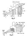
x-ray tube 60 directing a spread beam ofx-rays 62 through a patient P toward thedetector arrangement 64. Fore andaft collimators - The detector includes a first (front)
array 70 of detector elements and a second (back)array 72 of detector elements located behind the first array with respect to the x-ray tube. Bothe the first and second arrays are aligned with the fore and aft slits. Radiation from the x-ray tube falls upon, and is partially absorbed by, the first array, and the remainder of the radiation, passing through the first array, falls upon and is detected by the second array. In this way, separate dual energy response is obtained, as explained in the Barnes published application incorporated above. - Each cf the arrays includes a single line of detector elements arranged along an arcuate path defined by a portion of a circle having its centre located at a
focal spot 74 of the x-ray tube. - The detector arrays scan along arcuate paths concentric with the path indicated by the
arrows 69. The concentric paths are centered about a vertical scanning axis 75 extending through the tubefocal spot 74. The axis 77 is approximately perpendicular to the scanning axis 75. - This geometry reduces the non-uniformity of the x-ray energy across the beam set 62 propagating through the
collimator - In the Figure 3 embodiment, the axis 77 is also tilted slightly from the perpendicular to the approximate plane defined by the aligned
collimators - Each detector element comprises a photodiode. Overlying each photodiode is a scintillation material responsive to x-rays to produce visible light energy.
- The scintillation material used in connection with the first array differs from that used in connection with the second array. The scintillation material associated with the first array is selected for its ability to absorb and produce light in response tc x-rays from the source falling primarily within a relatively low energy range. The higher energy x-rays pass through the first array and fall on the second array, causing the scintillation material associated with the second array to produce light which is detected by the individual detector photodiodes of the second array. Suitable types, thicknesses and physical configurations of the scintillation material are defined in the above incorporated Barnes published European patent application.
- The preferred detector embodiments of this invention described can suitably include a radiation filter, made of copper or brass sheet or other similar material, located at the region indicated by
reference character 73, to "harden" the radiation energy reaching the second detector layer or array. Such filter elements are used to improve energy discrimination between the two detector layers in ways as are described in the above incorporated Barnes published European patent application. - The scintillation or phosphor material used in conjunction with the individual photodiode arrays discussed herein can suitably comprise a uniform single portion or layer of phosphor material overlying the entirety of the photodiode array without breaks or interruptions in its surface. Thus, the configuration of this embodiment forms a uniform smooth curved surface which comprises the energy receiving face of the detector array.
- In another embodiment, each detector element photodiode can be provided with its own individual portion of scintillation phosphor material, rather than the entire array being covered with a single piece of such material. In this latter embodiment, the individual receiving faces of each of the detector elements, with their scintillators, collectively form a curved surface which is approximately smooth.
- Known electronic and/or software correction means can be used to compensate, if need be, for any non-uniformity of transmission characteristics through the front detector array. This correction means can be associated with
data processor 44. - Figure 4 illustrates another embodiment of the invention in the form of an alternate detector array configuration. In Figure 4, energy from an
x-ray tube 80 is directed through a collimator (not shown) and in anarea beam 82 through the patient, emerging therefrom to all in a relatively large area of adetector assembly 84. In the embodiment of Figure 4, afirst detector array 86 includes a relatively large number of individual detector elements arranged in an area pattern, with the receiving surface of the first detector array collectively defining a portion of a sphere having its centre at afocal spot 87 of the x-ray tube. The detector element arrangement (not shown) is as described in the above incorporated Kurger patent. - A second
similar detector array 88 is located behind the first array with respect to the x-ray tube. The second array has a receiving surface defined by a portion of a sphere having a radius slightly larger than the sphere referred to in connection with the first array, and whose centre is also located at the x-ray tube focal spot. - The source/detector arrangement shown in Figure 4 incorporating the area beam can, but need not, be scanned. That is, the area beam can be directed constantly or in pulsed mode to pass simultaneously through a predetermined relatively large area of the patient's body, or ghe beam and detector can be scanned in unison,analogous to the manner of scanning described in connection with Figure 1.
- An alternative embodiment employs the spherically or cylindrically configured, detector arrays of Figure 4 and in Figures 5-7 (described below) in conjunction with the thin spread beam and collimator arrangement as illustrated in Figure 3. In this alternate embodiment, the spread beam is scanned across the area detector, the detector remaining stationary relative to the patient.
- Techniques for processing image data from non- scanned detector arrays, or single line scanned arrays in digital radiography are well known. Data processing of scanned multi-linear arrays is discussed below.
- Other embodiments of focussed detector configurations in accordance with the invention are illustrated in Figures 5 and 6. Figure 5 shows a portion of each of two stacked
detector arrays detector elements 96 whose receiving surfaces collectively define approximately a portion of a cylinder having a horizontal axis intersecting the focal spot of the x-ray tube. Either a single layer, or a dual layer, or "stacked" detector, as shown, can be used. - Figure 6 illustrates another embodiment, wherein the detector element receiving faces 95 define collectively a portion of a cylinder having a vertical axis through the x-ray tube focal spot. A dual layer (97,99) arrangement is shown, but a single layer can be used if desired.
- It is important to note that in the detector arrangement of Figures 4-7, (Figure 7 to be discussed below) known time delay and integration (TDI) circuitry can be employed, where the beam and detector are synchronously scanned, to enhance the signal-to-noise ratio of information derived from the scanned detector. In the embodiment of Figure 4, for example, a rectangular array of detector elements can be used. When such an array is used, the techniques for employing TDI output signal enhancement are described in the above incorporated Kruger patent. The embodiments of Figures 5-7 can also incorporate rectangular arrays of elements and TDI.
- A further aspect of this invention is illustrated in Figures 5-7. Figure 7, for example, depicts a portion of a double layer (101, 103) spherical (three dimensionally curved)
detector assembly 104, similar to that of Figure 4, but wherein individual detector elements are arranged in a staggered fashion. Figures 5 and 6 illustrate embodiments wherein the detector elements are arranged in staggered patterns and collectively define a portion of a cylinder. - In the embodiments of Figures 5-7, incorporating staggered arrays of detector elements, time delay and integrate (TDI) signal enhancement techniques can also be employed. Apparatus and circuitry for implementing TDI principles to processing of information from staggered detector arrays are set forth in detail in the above incorporated Sones et al application.
- Each column (extending substantially vertically in Figures 5-7) is offset vertically from its adjacent columns by a distance equal to one half the centre-to centre spacing between adjacent elements along a column.
- It should be understood that, while the preferred embodiments described herein are intended to include a dual layered stacked detector, the invention also encompasses embodiments similar to those of the Figures, but employing only single layer focussed detectors.
- Similarly, the embodiments described herein could include more than two stacked detector layers used analogously to those described here.
- Also, it should be understood that each of the embodiments of Figures 4-7 preferably include a beam hardening filter analogous to the
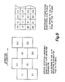
filter 73 shown in Figure 3, and the x-ray tube geometry described in connection with Figures 1 and 3. - The relationships among teh signals appearing in the various TDI sampling periods and among the various detector elements, in implementing the TDI technique in conjunction with the staggered array, are represented by the following relation: The total accumulated charge correspondign to the j-th pixel of the i-th row, i.e., P (i j), of the total derived image is given by the following expression:

- d(m,n,k) = the charge accumulated in the n-th detector element of the m-th row during the k-th sampling period, and
- N = the number of detector elements per row.
- See Figure 8 for a graphical representation of the notation of the above equation.
- While the descriptions of embodiments of this invention have discussed primarily the use of curved arrays of individual detector elements, the invention also emcompasses the use of curved portions of x-ray film, and curved portions of storage phosphor material responsive to x-rays.
- It is to be understood that the foregoing description of the present invention is intended as illustrative, rather than exhaustive, of the invention. Those of ordinary skill in the relevant art may be able to make certain additions, deletions or modifications to the subject matter described above, without the spirit or the scope of this invention, as defined in the appended claims.
Claims (14)
Applications Claiming Priority (2)
| Application Number | Priority Date | Filing Date | Title |
|---|---|---|---|
| US06/673,779 US4709382A (en) | 1984-11-21 | 1984-11-21 | Imaging with focused curved radiation detectors |
| US673779 | 1984-11-21 |
Publications (4)
| Publication Number | Publication Date |
|---|---|
| EP0182529A2 true EP0182529A2 (en) | 1986-05-28 |
| EP0182529A3 EP0182529A3 (en) | 1987-08-05 |
| EP0182529B1 EP0182529B1 (en) | 1991-09-18 |
| EP0182529B2 EP0182529B2 (en) | 2001-11-28 |
Family
ID=24704089
Family Applications (1)
| Application Number | Title | Priority Date | Filing Date |
|---|---|---|---|
| EP85307968A Expired - Lifetime EP0182529B2 (en) | 1984-11-21 | 1985-11-04 | Radiographic system |
Country Status (5)
| Country | Link |
|---|---|
| US (1) | US4709382A (en) |
| EP (1) | EP0182529B2 (en) |
| JP (1) | JP2515973B2 (en) |
| CA (1) | CA1239485A (en) |
| DE (1) | DE3584140D1 (en) |
Cited By (5)
| Publication number | Priority date | Publication date | Assignee | Title |
|---|---|---|---|---|
| EP1623672A1 (en) * | 2004-08-04 | 2006-02-08 | Siemens Aktiengesellschaft | X-ray apparatus, in particular for a device for x-ray mammography |
| US7340030B2 (en) | 2003-02-20 | 2008-03-04 | Koninklijke Philips Electronics N.V. | Asymmetric cone beam |
| US7440603B2 (en) | 2004-09-30 | 2008-10-21 | General Electric Company | Method and system for multi-energy tomosynthesis |
| WO2017116684A3 (en) * | 2015-12-28 | 2017-09-21 | L-3 Communications Security & Detection Systems, Inc. | Reference detector for correcting fluctuations in dose and energy of x-ray sources |
| US10729394B1 (en) | 2017-07-18 | 2020-08-04 | Carestream Health, Inc. | Portable scanning system for imaging patients |
Families Citing this family (113)
| Publication number | Priority date | Publication date | Assignee | Title |
|---|---|---|---|---|
| US4845731A (en) * | 1985-06-05 | 1989-07-04 | Picker International | Radiation data acquistion |
| US5054048A (en) * | 1985-11-14 | 1991-10-01 | Hologic, Inc. | X-ray radiography method and system |
| US4980904A (en) * | 1985-11-15 | 1990-12-25 | Picker International, Inc. | Radiation imaging calibration |
| FR2601578B1 (en) * | 1986-07-18 | 1988-09-16 | Commissariat Energie Atomique | APPARATUS FOR DETERMINING BONE MINERAL CONTENT. |
| US4881251A (en) * | 1986-07-31 | 1989-11-14 | Kabushiki Kaisha Toshiba | Computed tomograph apparatus |
| JPS6395033A (en) * | 1986-10-09 | 1988-04-26 | 株式会社日立製作所 | Spectral radiation image pickup apparatus |
| JPH07114768B2 (en) * | 1987-04-22 | 1995-12-13 | 松下電器産業株式会社 | X-ray diagnostic device |
| US4833327A (en) * | 1987-04-29 | 1989-05-23 | Hiram Hart | High-resolution radioisotopic imaging system |
| US4937453A (en) * | 1987-05-06 | 1990-06-26 | Nelson Robert S | X-ray detector for radiographic imaging |
| US4873708A (en) * | 1987-05-11 | 1989-10-10 | General Electric Company | Digital radiographic imaging system and method therefor |
| US4872188A (en) * | 1987-11-27 | 1989-10-03 | Picker International, Inc. | Registration correction for radiographic scanners with sandwich detectors |
| US5018177A (en) * | 1989-06-01 | 1991-05-21 | Board Of Regents, The University Of Texas System | Apparatus and method for producing digital panoramic x-ray images |
| US5150394A (en) * | 1989-12-05 | 1992-09-22 | University Of Massachusetts Medical School | Dual-energy system for quantitative radiographic imaging |
| US6031892A (en) | 1989-12-05 | 2000-02-29 | University Of Massachusetts Medical Center | System for quantitative radiographic imaging |
| US5841832A (en) * | 1991-02-13 | 1998-11-24 | Lunar Corporation | Dual-energy x-ray detector providing spatial and temporal interpolation |
| US5214686A (en) * | 1991-12-13 | 1993-05-25 | Wake Forest University | Three-dimensional panoramic dental radiography method and apparatus which avoids the subject's spine |
| US5334843A (en) * | 1992-08-17 | 1994-08-02 | Zeman Herbert D | Composite scintillator screen |
| US5305368A (en) * | 1992-09-14 | 1994-04-19 | Lunar Corporation | Method and apparatus for piece-wise radiographic scanning |
| USRE36162E (en) * | 1992-09-14 | 1999-03-23 | Lunar Corporation | Whole-body dual-energy bone densitometry using a narrow angle fan beam to cover the entire body in successive scans |
| US5596200A (en) * | 1992-10-14 | 1997-01-21 | Primex | Low dose mammography system |
| US5648996A (en) * | 1995-08-04 | 1997-07-15 | Omega International Technology, Inc. | Tangential computerized tomography scanner |
| US5617465A (en) * | 1995-12-08 | 1997-04-01 | Xedar Corporation | Scan-type X-ray imaging with fixed converter |
| US5933473A (en) * | 1996-04-04 | 1999-08-03 | Hitachi, Ltd. | Non-destructive inspection apparatus and inspection system using it |
| DE59813247D1 (en) * | 1997-02-17 | 2006-01-05 | Sirona Dental Systems Gmbh | Method and device for creating X-ray images of human body parts |
| EP0908743B1 (en) * | 1997-10-01 | 2006-07-05 | Siemens Aktiengesellschaft | X-RAY detector |
| US6278760B1 (en) * | 1998-11-13 | 2001-08-21 | Fuji Photo Film Co., Ltd. | Radiation image forming method and apparatus |
| US8565860B2 (en) | 2000-08-21 | 2013-10-22 | Biosensors International Group, Ltd. | Radioactive emission detector equipped with a position tracking system |
| US8909325B2 (en) | 2000-08-21 | 2014-12-09 | Biosensors International Group, Ltd. | Radioactive emission detector equipped with a position tracking system and utilization thereof with medical systems and in medical procedures |
| US8489176B1 (en) | 2000-08-21 | 2013-07-16 | Spectrum Dynamics Llc | Radioactive emission detector equipped with a position tracking system and utilization thereof with medical systems and in medical procedures |
| DE60038398T2 (en) * | 2000-08-28 | 2009-04-02 | Nauchno-Proizvodstvennoe Chastnoe Unitarnoe Predpriyatie Adani | Method and apparatus for X-ray scanning of bodies |
| US6895077B2 (en) * | 2001-11-21 | 2005-05-17 | University Of Massachusetts Medical Center | System and method for x-ray fluoroscopic imaging |
| US7297958B2 (en) * | 2001-12-03 | 2007-11-20 | Hitachi, Ltd. | Radiological imaging apparatus |
| EP1316818A3 (en) * | 2001-12-03 | 2012-04-11 | Hitachi, Ltd. | Radiological imaging apparatus |
| US7333588B2 (en) * | 2001-12-14 | 2008-02-19 | Wisconsin Alumni Research Foundation | Virtual spherical anode computed tomography |
| US20030128801A1 (en) * | 2002-01-07 | 2003-07-10 | Multi-Dimensional Imaging, Inc. | Multi-modality apparatus for dynamic anatomical, physiological and molecular imaging |
| CA2492587A1 (en) * | 2002-07-17 | 2004-01-22 | Christian Joram | Gamma ray detector for positron emission tomography (pet) and single photon emmission computed tomography (spect) |
| US7963695B2 (en) | 2002-07-23 | 2011-06-21 | Rapiscan Systems, Inc. | Rotatable boom cargo scanning system |
| US8275091B2 (en) | 2002-07-23 | 2012-09-25 | Rapiscan Systems, Inc. | Compact mobile cargo scanning system |
| DE10244176A1 (en) * | 2002-09-23 | 2004-04-08 | Siemens Ag | X-ray detector for use in digital imaging, especially CT applications, has a multi-layer structure with interleaved support, fluorescing and photo-sensor layers to permit energy-resolved radiation detection |
| US20040120457A1 (en) * | 2002-12-20 | 2004-06-24 | University Of Massachusetts Medical Center | Scatter reducing device for imaging |
| DE10311628B4 (en) * | 2003-03-14 | 2006-04-13 | Siemens Ag | imaging |
| GB0311881D0 (en) * | 2003-05-22 | 2003-06-25 | Univ Aberdeen | A detector module for detecting ionizing radiation |
| US6928141B2 (en) | 2003-06-20 | 2005-08-09 | Rapiscan, Inc. | Relocatable X-ray imaging system and method for inspecting commercial vehicles and cargo containers |
| DE10330595A1 (en) * | 2003-07-07 | 2005-02-17 | Siemens Ag | X-ray detector and method for producing X-ray images with spectral resolution |
| US7010092B2 (en) * | 2003-08-08 | 2006-03-07 | Imaging Dynamics Company Ltd. | Dual energy imaging using optically coupled digital radiography system |
| US7039163B2 (en) * | 2003-09-11 | 2006-05-02 | Siemens Aktiengesellschaft | Method for automatically setting an X-ray dosage for producing an X-ray tomographic image |
| WO2005052636A1 (en) * | 2003-11-28 | 2005-06-09 | Philips Intellectual Property & Standards Gmbh | Radiation detector module |
| US7968851B2 (en) | 2004-01-13 | 2011-06-28 | Spectrum Dynamics Llc | Dynamic spect camera |
| US8586932B2 (en) | 2004-11-09 | 2013-11-19 | Spectrum Dynamics Llc | System and method for radioactive emission measurement |
| US9470801B2 (en) | 2004-01-13 | 2016-10-18 | Spectrum Dynamics Llc | Gating with anatomically varying durations |
| WO2008010227A2 (en) | 2006-07-19 | 2008-01-24 | Spectrum Dynamics Llc | Imaging protocols |
| WO2005067383A2 (en) | 2004-01-13 | 2005-07-28 | Spectrum Dynamics Llc | Multi-dimensional image reconstruction |
| US8571881B2 (en) | 2004-11-09 | 2013-10-29 | Spectrum Dynamics, Llc | Radiopharmaceutical dispensing, administration, and imaging |
| US20050161609A1 (en) * | 2004-01-16 | 2005-07-28 | Bjoern Heismann | X-ray detector module for spectrally resolved measurements |
| EP1778957A4 (en) | 2004-06-01 | 2015-12-23 | Biosensors Int Group Ltd | Radioactive-emission-measurement optimization to specific body structures |
| US20080043903A1 (en) * | 2004-06-07 | 2008-02-21 | Fang-Fang Yin | Image-Guided Intensity-Modulated X-Ray Brachytherapy System |
| US8000773B2 (en) | 2004-11-09 | 2011-08-16 | Spectrum Dynamics Llc | Radioimaging |
| US9316743B2 (en) | 2004-11-09 | 2016-04-19 | Biosensors International Group, Ltd. | System and method for radioactive emission measurement |
| US9943274B2 (en) | 2004-11-09 | 2018-04-17 | Spectrum Dynamics Medical Limited | Radioimaging using low dose isotope |
| US8615405B2 (en) | 2004-11-09 | 2013-12-24 | Biosensors International Group, Ltd. | Imaging system customization using data from radiopharmaceutical-associated data carrier |
| EP1827505A4 (en) | 2004-11-09 | 2017-07-12 | Biosensors International Group, Ltd. | Radioimaging |
| US7471764B2 (en) | 2005-04-15 | 2008-12-30 | Rapiscan Security Products, Inc. | X-ray imaging system having improved weather resistance |
| EP1909853B1 (en) | 2005-07-19 | 2015-03-18 | Biosensors International Group, Ltd. | Imaging protocols |
| US8837793B2 (en) | 2005-07-19 | 2014-09-16 | Biosensors International Group, Ltd. | Reconstruction stabilizer and active vision |
| JP2007040945A (en) * | 2005-08-01 | 2007-02-15 | Chiyoda Technol Corp | Device for calibration device for measuring dose such as radiation |
| JP2007136050A (en) * | 2005-11-22 | 2007-06-07 | National Univ Corp Shizuoka Univ | X-ray detector array |
| US7526064B2 (en) | 2006-05-05 | 2009-04-28 | Rapiscan Security Products, Inc. | Multiple pass cargo inspection system |
| US8894974B2 (en) | 2006-05-11 | 2014-11-25 | Spectrum Dynamics Llc | Radiopharmaceuticals for diagnosis and therapy |
| US8488736B2 (en) * | 2006-09-19 | 2013-07-16 | General Electric Company | Stacked flat panel x-ray detector assembly and method of making same |
| US8483352B2 (en) * | 2006-09-19 | 2013-07-09 | General Electric Company | Stacked x-ray detector assembly and method of making same |
| US8483353B2 (en) * | 2006-09-19 | 2013-07-09 | General Electric Company | Integrated X-ray detector assembly and method of making same |
| US8610075B2 (en) | 2006-11-13 | 2013-12-17 | Biosensors International Group Ltd. | Radioimaging applications of and novel formulations of teboroxime |
| WO2008075362A2 (en) | 2006-12-20 | 2008-06-26 | Spectrum Dynamics Llc | A method, a system, and an apparatus for using and processing multidimensional data |
| US7869566B2 (en) * | 2007-06-29 | 2011-01-11 | Morpho Detection, Inc. | Integrated multi-sensor systems for and methods of explosives detection |
| US8521253B2 (en) | 2007-10-29 | 2013-08-27 | Spectrum Dynamics Llc | Prostate imaging |
| US9118635B2 (en) * | 2007-11-02 | 2015-08-25 | General Electric Company | Medical imaging system |
| GB0803644D0 (en) | 2008-02-28 | 2008-04-02 | Rapiscan Security Products Inc | Scanning systems |
| GB0803641D0 (en) * | 2008-02-28 | 2008-04-02 | Rapiscan Security Products Inc | Scanning systems |
| US9036779B2 (en) | 2008-02-28 | 2015-05-19 | Rapiscan Systems, Inc. | Dual mode X-ray vehicle scanning system |
| GB0803640D0 (en) | 2008-02-28 | 2008-04-02 | Rapiscan Security Products Inc | Scanning systems |
| GB0803642D0 (en) | 2008-02-28 | 2008-04-02 | Rapiscan Security Products Inc | Drive-through scanning systems |
| GB0803643D0 (en) | 2008-02-28 | 2008-04-02 | Rapiscan Security Products Inc | Mobile scanning systems |
| GB0809109D0 (en) | 2008-05-20 | 2008-06-25 | Rapiscan Security Products Inc | Scanner systems |
| GB0809107D0 (en) | 2008-05-20 | 2008-06-25 | Rapiscan Security Products Inc | Scannign systems |
| GB0809110D0 (en) | 2008-05-20 | 2008-06-25 | Rapiscan Security Products Inc | Gantry scanner systems |
| US8963094B2 (en) | 2008-06-11 | 2015-02-24 | Rapiscan Systems, Inc. | Composite gamma-neutron detection system |
| GB0810638D0 (en) | 2008-06-11 | 2008-07-16 | Rapiscan Security Products Inc | Photomultiplier and detection systems |
| DE102009045092A1 (en) * | 2008-09-29 | 2010-12-09 | Friedrich-Alexander-Universität Erlangen-Nürnberg | Device and method for time-delayed integration on an X-ray detector composed of a plurality of detector modules |
| EP2178048A3 (en) * | 2008-09-29 | 2017-07-19 | MIR Medical Imaging Research Holding GmbH | Method for defining a coordination system of a female breast tailored to the patient |
| US20100128843A1 (en) * | 2008-11-22 | 2010-05-27 | Mir Medical Imaging Research Holding Gmbh | Device for Locating a Female Breast for Diagnostic Imaging and Intervention |
| US9310323B2 (en) | 2009-05-16 | 2016-04-12 | Rapiscan Systems, Inc. | Systems and methods for high-Z threat alarm resolution |
| JP2010278295A (en) * | 2009-05-29 | 2010-12-09 | Nec Toshiba Space Systems Ltd | Image capturing apparatus and method of arranging imaging element |
| JP2011019891A (en) * | 2009-07-20 | 2011-02-03 | Katsuhisa Hosono | Multispectral detector for x-ray |
| US8338788B2 (en) | 2009-07-29 | 2012-12-25 | Spectrum Dynamics Llc | Method and system of optimized volumetric imaging |
| JP5467830B2 (en) | 2009-09-18 | 2014-04-09 | 浜松ホトニクス株式会社 | Radiation detector |
| JP5295915B2 (en) * | 2009-09-18 | 2013-09-18 | 浜松ホトニクス株式会社 | Radiation detector |
| JP5457118B2 (en) | 2009-09-18 | 2014-04-02 | 浜松ホトニクス株式会社 | Radiation detector |
| JP5605607B2 (en) * | 2010-03-19 | 2014-10-15 | 横河電機株式会社 | X-ray measuring device |
| JP5610885B2 (en) | 2010-07-12 | 2014-10-22 | キヤノン株式会社 | X-ray imaging apparatus and imaging method |
| JP5638914B2 (en) * | 2010-10-27 | 2014-12-10 | 株式会社アールエフ | Radiation imaging device |
| WO2012064843A2 (en) * | 2010-11-09 | 2012-05-18 | Savannah River Nuclear Solutions, Llc | System and method for the identification of radiation in contaminated rooms |
| ES2938411T3 (en) | 2011-02-08 | 2023-04-10 | Rapiscan Systems Inc | Covert surveillance using multimodality detection |
| US9218933B2 (en) | 2011-06-09 | 2015-12-22 | Rapidscan Systems, Inc. | Low-dose radiographic imaging system |
| CN103308535B (en) * | 2012-03-09 | 2016-04-13 | 同方威视技术股份有限公司 | For equipment and the method for ray scanning imaging |
| US9091628B2 (en) | 2012-12-21 | 2015-07-28 | L-3 Communications Security And Detection Systems, Inc. | 3D mapping with two orthogonal imaging views |
| US9791590B2 (en) | 2013-01-31 | 2017-10-17 | Rapiscan Systems, Inc. | Portable security inspection system |
| KR102279966B1 (en) * | 2013-12-23 | 2021-07-21 | 주식회사 바텍 | Dental x-ray imaging apparatus |
| US9557427B2 (en) | 2014-01-08 | 2017-01-31 | Rapiscan Systems, Inc. | Thin gap chamber neutron detectors |
| JP2016043018A (en) * | 2014-08-22 | 2016-04-04 | コニカミノルタ株式会社 | Radiation imaging system |
| JP2019515280A (en) * | 2016-05-03 | 2019-06-06 | ラピスカン システムズ、インコーポレイテッド | Radiation signal processing system |
| US11197643B2 (en) * | 2018-03-16 | 2021-12-14 | Mobius Imaging, Llc | Medical x-ray imaging systems and methods |
| EP3553568A1 (en) * | 2018-04-12 | 2019-10-16 | Koninklijke Philips N.V. | X-ray detector with focused scintillator structure for uniform imaging |
| WO2022183191A1 (en) | 2021-02-23 | 2022-09-01 | Rapiscan Systems, Inc. | Systems and methods for eliminating cross-talk in scanning systems having multiple x-ray sources |
Citations (6)
| Publication number | Priority date | Publication date | Assignee | Title |
|---|---|---|---|---|
| GB2034149A (en) * | 1978-09-29 | 1980-05-29 | Tokyo Shibaura Electric Co | X-ray apparatus for computed tomography scanner |
| US4284895A (en) * | 1978-02-21 | 1981-08-18 | Ira Lon Morgan | Method and apparatus for tomographic examination of an object by penetrating radiation |
| DE3021757A1 (en) * | 1980-06-10 | 1981-12-24 | Siemens AG, 1000 Berlin und 8000 München | Radiography X-ray unit - uses deflection electrodes to adjust beam focus and obtain different transverse sections of patient |
| US4383327A (en) * | 1980-12-01 | 1983-05-10 | University Of Utah | Radiographic systems employing multi-linear arrays of electronic radiation detectors |
| DE3311931A1 (en) * | 1982-03-31 | 1983-10-13 | Tokyo Shibaura Denki K.K., Kawasaki | RADIATION DETECTOR |
| EP0115125A1 (en) * | 1982-11-26 | 1984-08-08 | The Board Of Trustees Of The University Of Alabama For Its Division University Of Alabama In Birmingham | Radiation detectors and energy discriminating apparatus and methods using such detectors |
Family Cites Families (23)
| Publication number | Priority date | Publication date | Assignee | Title |
|---|---|---|---|---|
| US4206361A (en) * | 1972-05-17 | 1980-06-03 | E M I Limited | Radiography |
| US4069422A (en) * | 1973-06-01 | 1978-01-17 | E M I Limited | Apparatus for examining objects by means of penetrating radiation |
| US3965358A (en) * | 1974-12-06 | 1976-06-22 | Albert Macovski | Cross-sectional imaging system using a polychromatic x-ray source |
| US4015129A (en) * | 1975-11-28 | 1977-03-29 | Picker Corporation | Position indicating control method and apparatus in radiation scanning systems |
| US4096390A (en) * | 1976-02-18 | 1978-06-20 | Emi Limited | Apparatus for examining objects by means of penetrating radiation |
| US4190772A (en) * | 1976-04-19 | 1980-02-26 | Varian Associates, Inc. | Tomographic scanning apparatus having detector signal digitizing means mounted to rotate with detectors |
| NL7605253A (en) * | 1976-05-17 | 1977-11-21 | Optische Ind De Oude Delft Nv | DEVICE FOR TOMOGRAPHY. |
| US4029963A (en) * | 1976-07-30 | 1977-06-14 | The Board Of Trustees Of Leland Stanford Junior University | X-ray spectral decomposition imaging system |
| DE2717349A1 (en) * | 1977-04-19 | 1978-10-26 | Siemens Ag | ROENTINE LAYER FOR THE PRODUCTION OF TRANSVERSAL LAYER IMAGES |
| DE2723401A1 (en) * | 1977-05-24 | 1978-12-07 | Siemens Ag | LAYER FOR THE PRODUCTION OF TRANSVERSAL LAYER IMAGES |
| US4298800A (en) * | 1978-02-27 | 1981-11-03 | Computome Corporation | Tomographic apparatus and method for obtaining three-dimensional information by radiation scanning |
| US4247774A (en) * | 1978-06-26 | 1981-01-27 | The United States Of America As Represented By The Department Of Health, Education And Welfare | Simultaneous dual-energy computer assisted tomography |
| JPS5599087A (en) * | 1979-01-23 | 1980-07-28 | Shimadzu Corp | Emission type tomography |
| US4442489A (en) * | 1979-06-16 | 1984-04-10 | U.S. Philips Corporation | Device for computed tomography |
| DE2924423A1 (en) * | 1979-06-16 | 1980-12-18 | Philips Patentverwaltung | METHOD FOR DETERMINING THE SPATIAL DISTRIBUTION OF THE ABSORPTION OF RADIATION IN A PLANE AREA |
| US4355409A (en) * | 1979-08-31 | 1982-10-19 | Kurt Amplatz | Scanning x-ray system |
| DE3010780A1 (en) * | 1980-03-20 | 1981-09-24 | Siemens AG, 1000 Berlin und 8000 München | RAY DIAGNOSTIC DEVICE |
| US4315157A (en) * | 1980-05-01 | 1982-02-09 | The University Of Alabama In Birmingham | Multiple beam computed tomography (CT) scanner |
| US4426721A (en) * | 1980-10-07 | 1984-01-17 | Diagnostic Information, Inc. | X-ray intensifier detector system for x-ray electronic radiography |
| US4366574A (en) * | 1980-10-31 | 1982-12-28 | Technicare Corporation | Shadowgraphic slit scanner with video display |
| EP0089148B1 (en) * | 1982-03-15 | 1987-02-25 | The Board Of Trustees Of The Leland Stanford Junior University | Multiple line detector for use in radiography |
| JPS58159729A (en) * | 1982-03-17 | 1983-09-22 | 株式会社東芝 | Radioactive ray fluoroscopic apparatus |
| US4511799A (en) * | 1982-12-10 | 1985-04-16 | American Science And Engineering, Inc. | Dual energy imaging |
-
1984
- 1984-11-21 US US06/673,779 patent/US4709382A/en not_active Expired - Fee Related
-
1985
- 1985-10-30 CA CA000494248A patent/CA1239485A/en not_active Expired
- 1985-11-04 EP EP85307968A patent/EP0182529B2/en not_active Expired - Lifetime
- 1985-11-04 DE DE8585307968T patent/DE3584140D1/en not_active Expired - Lifetime
- 1985-11-21 JP JP60262350A patent/JP2515973B2/en not_active Expired - Fee Related
Patent Citations (6)
| Publication number | Priority date | Publication date | Assignee | Title |
|---|---|---|---|---|
| US4284895A (en) * | 1978-02-21 | 1981-08-18 | Ira Lon Morgan | Method and apparatus for tomographic examination of an object by penetrating radiation |
| GB2034149A (en) * | 1978-09-29 | 1980-05-29 | Tokyo Shibaura Electric Co | X-ray apparatus for computed tomography scanner |
| DE3021757A1 (en) * | 1980-06-10 | 1981-12-24 | Siemens AG, 1000 Berlin und 8000 München | Radiography X-ray unit - uses deflection electrodes to adjust beam focus and obtain different transverse sections of patient |
| US4383327A (en) * | 1980-12-01 | 1983-05-10 | University Of Utah | Radiographic systems employing multi-linear arrays of electronic radiation detectors |
| DE3311931A1 (en) * | 1982-03-31 | 1983-10-13 | Tokyo Shibaura Denki K.K., Kawasaki | RADIATION DETECTOR |
| EP0115125A1 (en) * | 1982-11-26 | 1984-08-08 | The Board Of Trustees Of The University Of Alabama For Its Division University Of Alabama In Birmingham | Radiation detectors and energy discriminating apparatus and methods using such detectors |
Cited By (8)
| Publication number | Priority date | Publication date | Assignee | Title |
|---|---|---|---|---|
| US7340030B2 (en) | 2003-02-20 | 2008-03-04 | Koninklijke Philips Electronics N.V. | Asymmetric cone beam |
| EP1623672A1 (en) * | 2004-08-04 | 2006-02-08 | Siemens Aktiengesellschaft | X-ray apparatus, in particular for a device for x-ray mammography |
| US7286645B2 (en) | 2004-08-04 | 2007-10-23 | Siemens Aktiengesellschaft | X-ray device that emits an x-ray beam with a scanning-like movement |
| US7315610B2 (en) | 2004-08-04 | 2008-01-01 | Siemens Aktiengesellschaft | X-ray device that emits an x-ray beam with a scanning-like movement |
| US7440603B2 (en) | 2004-09-30 | 2008-10-21 | General Electric Company | Method and system for multi-energy tomosynthesis |
| WO2017116684A3 (en) * | 2015-12-28 | 2017-09-21 | L-3 Communications Security & Detection Systems, Inc. | Reference detector for correcting fluctuations in dose and energy of x-ray sources |
| US9980697B2 (en) | 2015-12-28 | 2018-05-29 | L-3 Communications Security & Detection Systems, Inc. | Reference detector for correcting fluctuations in dose and energy of x-ray sources |
| US10729394B1 (en) | 2017-07-18 | 2020-08-04 | Carestream Health, Inc. | Portable scanning system for imaging patients |
Also Published As
| Publication number | Publication date |
|---|---|
| CA1239485A (en) | 1988-07-19 |
| EP0182529B1 (en) | 1991-09-18 |
| EP0182529B2 (en) | 2001-11-28 |
| US4709382A (en) | 1987-11-24 |
| DE3584140D1 (en) | 1991-10-24 |
| JPS61143038A (en) | 1986-06-30 |
| JP2515973B2 (en) | 1996-07-10 |
| EP0182529A3 (en) | 1987-08-05 |
Similar Documents
| Publication | Publication Date | Title |
|---|---|---|
| EP0182529B1 (en) | Radiographic system | |
| USRE37536E1 (en) | Split energy level radiation detection | |
| JP6759207B2 (en) | Static real-time CT image formation system and its image formation control method | |
| JP3487599B2 (en) | Improved X-ray volumetric CT scanner | |
| US4672649A (en) | Three dimensional scanned projection radiography using high speed computed tomographic scanning system | |
| US7310407B2 (en) | Nuclear medical imaging device | |
| EP1848985B1 (en) | Multiple mode flat panel x-ray imaging system | |
| US6183139B1 (en) | X-ray scanning method and apparatus | |
| EP0887661B1 (en) | Diagnostic imaging | |
| JP3449561B2 (en) | X-ray CT system | |
| JP2825450B2 (en) | CT scanner | |
| US4672648A (en) | Apparatus and method for radiation attenuation | |
| US4433427A (en) | Method and apparatus for examining a body by means of penetrating radiation such as X-rays | |
| CN110891489B (en) | Reference detector element in combination with an anti-scatter collimator | |
| US4573179A (en) | Scanned projection radiography using high speed computed tomographic scanning system | |
| JPH09215688A (en) | System for determining position of x-ray beam in multi-slice type computer aided tomography system | |
| JPH01500968A (en) | Tomographic image forming method and device | |
| JP2002148340A (en) | Diagnostic image forming nuclear medicine gamma ray camera and diagnostic image forming method by using it | |
| JPH0228818B2 (en) | ||
| EP1205767A2 (en) | Improved gamma camera imaging system | |
| US6380540B1 (en) | Radiation imaging using simultaneous emission and transmission | |
| US5629971A (en) | Scan speed for transmission exposure reduction in a nuclear medicine camera | |
| US6140649A (en) | Imaging attenuation correction employing simultaneous transmission/emission scanning | |
| US4514632A (en) | Modular scintillation camera | |
| US6208709B1 (en) | Detection processing system |
Legal Events
| Date | Code | Title | Description |
|---|---|---|---|
| PUAI | Public reference made under article 153(3) epc to a published international application that has entered the european phase |
Free format text: ORIGINAL CODE: 0009012 |
|
| AK | Designated contracting states |
Kind code of ref document: A2 Designated state(s): DE FR GB NL |
|
| PUAL | Search report despatched |
Free format text: ORIGINAL CODE: 0009013 |
|
| AK | Designated contracting states |
Kind code of ref document: A3 Designated state(s): DE FR GB NL |
|
| 17P | Request for examination filed |
Effective date: 19880118 |
|
| 17Q | First examination report despatched |
Effective date: 19900323 |
|
| GRAA | (expected) grant |
Free format text: ORIGINAL CODE: 0009210 |
|
| AK | Designated contracting states |
Kind code of ref document: B1 Designated state(s): DE FR GB NL |
|
| ET | Fr: translation filed | ||
| REF | Corresponds to: |
Ref document number: 3584140 Country of ref document: DE Date of ref document: 19911024 |
|
| PLBI | Opposition filed |
Free format text: ORIGINAL CODE: 0009260 |
|
| 26 | Opposition filed |
Opponent name: SIEMENS AKTIENGESELLSCHAFT, BERLIN UND MUENCHEN Effective date: 19911125 |
|
| NLR1 | Nl: opposition has been filed with the epo |
Opponent name: SIEMENS AKTIENGESELLSCHAFT |
|
| PGFP | Annual fee paid to national office [announced via postgrant information from national office to epo] |
Ref country code: GB Payment date: 19951002 Year of fee payment: 11 |
|
| PG25 | Lapsed in a contracting state [announced via postgrant information from national office to epo] |
Ref country code: GB Effective date: 19961104 |
|
| APAC | Appeal dossier modified |
Free format text: ORIGINAL CODE: EPIDOS NOAPO |
|
| APAC | Appeal dossier modified |
Free format text: ORIGINAL CODE: EPIDOS NOAPO |
|
| GBPC | Gb: european patent ceased through non-payment of renewal fee |
Effective date: 19961104 |
|
| APAE | Appeal reference modified |
Free format text: ORIGINAL CODE: EPIDOS REFNO |
|
| APAC | Appeal dossier modified |
Free format text: ORIGINAL CODE: EPIDOS NOAPO |
|
| PLAW | Interlocutory decision in opposition |
Free format text: ORIGINAL CODE: EPIDOS IDOP |
|
| PUAH | Patent maintained in amended form |
Free format text: ORIGINAL CODE: 0009272 |
|
| STAA | Information on the status of an ep patent application or granted ep patent |
Free format text: STATUS: PATENT MAINTAINED AS AMENDED |
|
| 27A | Patent maintained in amended form |
Effective date: 20011128 |
|
| AK | Designated contracting states |
Kind code of ref document: B2 Designated state(s): DE FR GB NL |
|
| NLR2 | Nl: decision of opposition | ||
| NLR3 | Nl: receipt of modified translations in the netherlands language after an opposition procedure | ||
| PGFP | Annual fee paid to national office [announced via postgrant information from national office to epo] |
Ref country code: NL Payment date: 20021011 Year of fee payment: 18 |
|
| PGFP | Annual fee paid to national office [announced via postgrant information from national office to epo] |
Ref country code: FR Payment date: 20031126 Year of fee payment: 19 |
|
| PGFP | Annual fee paid to national office [announced via postgrant information from national office to epo] |
Ref country code: DE Payment date: 20040121 Year of fee payment: 19 |
|
| PG25 | Lapsed in a contracting state [announced via postgrant information from national office to epo] |
Ref country code: NL Free format text: LAPSE BECAUSE OF NON-PAYMENT OF DUE FEES Effective date: 20040601 |
|
| NLV4 | Nl: lapsed or anulled due to non-payment of the annual fee |
Effective date: 20040601 |
|
| PG25 | Lapsed in a contracting state [announced via postgrant information from national office to epo] |
Ref country code: DE Free format text: LAPSE BECAUSE OF NON-PAYMENT OF DUE FEES Effective date: 20050601 |
|
| PG25 | Lapsed in a contracting state [announced via postgrant information from national office to epo] |
Ref country code: FR Free format text: LAPSE BECAUSE OF NON-PAYMENT OF DUE FEES Effective date: 20050729 |
|
| REG | Reference to a national code |
Ref country code: FR Ref legal event code: ST |
|
| APAH | Appeal reference modified |
Free format text: ORIGINAL CODE: EPIDOSCREFNO |