EP0181291A2 - Analytical assembly usable in apparatuses for optically determining species in solution - Google Patents
Analytical assembly usable in apparatuses for optically determining species in solution Download PDFInfo
- Publication number
- EP0181291A2 EP0181291A2 EP85810508A EP85810508A EP0181291A2 EP 0181291 A2 EP0181291 A2 EP 0181291A2 EP 85810508 A EP85810508 A EP 85810508A EP 85810508 A EP85810508 A EP 85810508A EP 0181291 A2 EP0181291 A2 EP 0181291A2
- Authority
- EP
- European Patent Office
- Prior art keywords
- cuvette
- waveguide
- solution
- signal
- disk
- Prior art date
- Legal status (The legal status is an assumption and is not a legal conclusion. Google has not performed a legal analysis and makes no representation as to the accuracy of the status listed.)
- Withdrawn
Links
Images
Classifications
-
- G—PHYSICS
- G01—MEASURING; TESTING
- G01N—INVESTIGATING OR ANALYSING MATERIALS BY DETERMINING THEIR CHEMICAL OR PHYSICAL PROPERTIES
- G01N21/00—Investigating or analysing materials by the use of optical means, i.e. using sub-millimetre waves, infrared, visible or ultraviolet light
- G01N21/75—Systems in which material is subjected to a chemical reaction, the progress or the result of the reaction being investigated
- G01N21/77—Systems in which material is subjected to a chemical reaction, the progress or the result of the reaction being investigated by observing the effect on a chemical indicator
- G01N21/7703—Systems in which material is subjected to a chemical reaction, the progress or the result of the reaction being investigated by observing the effect on a chemical indicator using reagent-clad optical fibres or optical waveguides
-
- G—PHYSICS
- G01—MEASURING; TESTING
- G01N—INVESTIGATING OR ANALYSING MATERIALS BY DETERMINING THEIR CHEMICAL OR PHYSICAL PROPERTIES
- G01N21/00—Investigating or analysing materials by the use of optical means, i.e. using sub-millimetre waves, infrared, visible or ultraviolet light
- G01N21/01—Arrangements or apparatus for facilitating the optical investigation
- G01N21/03—Cuvette constructions
- G01N2021/0325—Cells for testing reactions, e.g. containing reagents
-
- G—PHYSICS
- G01—MEASURING; TESTING
- G01N—INVESTIGATING OR ANALYSING MATERIALS BY DETERMINING THEIR CHEMICAL OR PHYSICAL PROPERTIES
- G01N2201/00—Features of devices classified in G01N21/00
- G01N2201/04—Batch operation; multisample devices
-
- Y—GENERAL TAGGING OF NEW TECHNOLOGICAL DEVELOPMENTS; GENERAL TAGGING OF CROSS-SECTIONAL TECHNOLOGIES SPANNING OVER SEVERAL SECTIONS OF THE IPC; TECHNICAL SUBJECTS COVERED BY FORMER USPC CROSS-REFERENCE ART COLLECTIONS [XRACs] AND DIGESTS
- Y10—TECHNICAL SUBJECTS COVERED BY FORMER USPC
- Y10S—TECHNICAL SUBJECTS COVERED BY FORMER USPC CROSS-REFERENCE ART COLLECTIONS [XRACs] AND DIGESTS
- Y10S436/00—Chemistry: analytical and immunological testing
- Y10S436/805—Optical property
-
- Y—GENERAL TAGGING OF NEW TECHNOLOGICAL DEVELOPMENTS; GENERAL TAGGING OF CROSS-SECTIONAL TECHNOLOGIES SPANNING OVER SEVERAL SECTIONS OF THE IPC; TECHNICAL SUBJECTS COVERED BY FORMER USPC CROSS-REFERENCE ART COLLECTIONS [XRACs] AND DIGESTS
- Y10—TECHNICAL SUBJECTS COVERED BY FORMER USPC
- Y10S—TECHNICAL SUBJECTS COVERED BY FORMER USPC CROSS-REFERENCE ART COLLECTIONS [XRACs] AND DIGESTS
- Y10S436/00—Chemistry: analytical and immunological testing
- Y10S436/807—Apparatus included in process claim, e.g. physical support structures
- Y10S436/81—Tube, bottle, or dipstick
Definitions
- the present invention concerns an assembly including an analytical cuvette and supporting means thereto usable in an apparatus for optically determining species in solution, more especially for determining bioactive species by reactions of the immunoassay type.
- Analytical apparatuses comprising optical fiber probes which can optically monitor the adsorption of chemical species on the fiber core are known.
- This technique is based on the immersion of a lit optical waveguide, for instance an optical fiber without cladding, in a test solution the refractive index of which is lower than that of the fiber core, whereby an interaction takes place between the evanescent wave conponent of the signal travelling along the waveguide and some species in solution to be determined.
- This approach is particularly interesting for monitoring events in the reaction space in close vicinity to the fiber, i.e.
- an apparatus for measuring parameters in a reaction of an analyte with a specific reactant thereto, said reaction occurring on the surface of a waveguide, e.g. a piece of optical fiber, and causing detectable changes to the optical properties thereof which comprises a light source, means to inject a signal from that source into the input of said waveguide, detecting means to detect the light signal having undergone changes when travelling therethrough and emerging therefrom and converting it to an electric signal, and means for processing said signal into useful data pertaining to said reaction.
- This apparatus comprises:
- US-A-4,406,547 discloses an apparatus for the automatic analysis of biological samples which holds a number of cuvettes disposed peripherally on a turntable operated step by step.
- the present assembly as defined in claim 1 is a solution to the afore-mentioned wishes.
- One embodiment of this assembly and an apparatus in which it can be incorporated as well as a modification will now be described with reference to the annexed drawing.
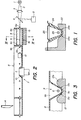
- Fig. 1 is a schematic cross-sectional simplified view of an assembly according to the invention.
- Fig. 2 is a schematic cross-sectional view of an analytical apparatus involving the use of a variant of the assembly of fig. 1.
- Fig. 3 is a schematic view in cross-section along line III-III of fig. 2 of a detail of the apparatus of fig. 2 at an enlarged scale.
- the assembly shown in fig. 1 comprises a cuvette 24 resting in a V-shaped groove of a carrier 23 and in contact with the walls thereof by two generants 23a of its bottom surface.
- the cuvettes of this embodiment are handled manually and slipped in correct position in the recess of carrier 23 as shown in the drawing; there, they are held in place by a spring 25.
- the cuvette 24 has a rounded bottom in the form of a portion of cylinder and a waveguide 26 is located at the center of the radius of curvature of this partially cylindrical bottom such as to ensure that its alignment relative to the optical means involved (which are not shown but similar to those disclosed hereafter remain accurate even if, for some reason, the cuvette is slightly tilted sidewise in the holder.
- the filling of the cuvette is done automatically with a dispenser (not shown) over the cuvette or, more commonly, by hand with a pipette.
- a dispenser not shown
- a pipette a pipette
- the holding means for accurately maintaining the waveguide of the cuvette in a correct optical orientation relative to the light injecting and detecting means are important not only in connection with a casual tilting of one particular cuvette but also for allowing the use of a full series of interchangeable cuvettes with identically rounded bottom and identically centered waveguide.
- the cuvettes may slightly differ in shape or in height, such possible variation being easily conpensated by the spring means 25.
- the apparatus represented in figs 2 and 3 comprises an excitation light source 1 providing a light beam 2 to be focussed by a focussing means 3 and split by a beam splitter 4 into a reference beam directed to a reference detector 5 and a test beam to be injected into the input end 6a of a waveguide 6.
- the present apparatus comprises a vat shaped disk 7 with a shouldered edge 8 carrying a plurality of molded cavities 9 which constitute the cuvettes to be filled with the solution of analytes to be analyzed with the present apparatus.
- the disk 7 is made of a plastic having sufficient strength, flexibility and resilience to accept temporary bending deformation and easily return to its original shape when the bending force is relieved. Plastics such as PVC, polythene, polystyrene and others are convenient.
- the disk 7 is pierced at the center with a tapered hole 10 to be adapted to the top of a shaft 11 conically shaped so as to match with the taper of hole 10.
- the shaft 11 is rotatable (by means of a motor not shown) which makes it possible to drive disk 7 horizontally into rotation.
- Each cuvette 9 is provided with a piece of optical fiber (waveguide) with both ends fitted through each opposite radial walls 9a, 9b thereof, such ends protruding externally from the cell, or being flush with the outside surface thereof, and constituting an input end 6a and an output end 6b, respectively of this waveguide.
- the inside portion of the fiber 6 to be immersed in the analyte solution is unclad so as to enable the evanescent wave component of the exciting wave signal travelling by multiple reflections through the guide to interact with the analyte in close vicinity thereto, i.e. a few tenth to a few hundredths of angstroems.
- the fiber is provided with a cladding 6c this being so to prevent undesirable optical effects of the plastic of the walls on the signal carried by the fiber.
- the present apparatus further comprises positioning means for the cuvette adapted for accurately positioning the waveguide of each cuvette, in turn, in facing relationship to the focussing means 3 and a signal detector 12 located in a fixed position opposite the incident beam 2 with regard to the cuvette 9.
- This detector 12 is supported by supporting means (not shown) to the main frame of the apparatus also not shown.
- the positioning means of the apparatus which, together with the cuvette constitute an assembly according to the invention comprise a V shaped carrier 13 whose slant walls support cuvette 9 on only two points 13a on both sides. This is made possible by virtue of the profile of the bottom 9c of cuvette 9 which is roondedly molded in the form of a portion of cylinder, as shown on the drawing, which ensures that such bottom only touches the walls of holder 13 at the two points 13a (or rather the two corresponding longitudinal generants extending on the length of the bottom 9c of the cuvette).
- Both input 6a and output ends 6b of the waveguide are accurately centered with regard to the radius of curvature of the rounded bottom 9c which ensures that casual sidewise tilting of the cuvette will not disturb the positioning of the waveguide relative to the incident beam and the detector.
- the external surface of the two side portions 13b of the carrier 13 are rounded off such as to allow the cuvettes 9 to ride over said portions upon rotation of the disk 7, thus enabling to stepwise position each cuvette, in turn, in correct orientation relative to the light excitation and detecting means, this being possible due to the disc's elasticity. Therefore, the disc can be rotated by steps each of which corresponds to one cell 9 coming in turn in facing relationship to the optical means for performing an analysis of a solution introduced into said cell. Of course, other means to provide such stepwise motion are also possible.
- the present apparatus also ccnprises means for filling the cuvette with the analyte solution to be tested.
- Such means are represented schematically in fig. 1 by a pipette 14.
- This pipette can be operated manually or automatically by means of a metered dispensing mechanism not represented which enables to introduce a well determined quantity of liquid into each cuvette at a selected time.
- a dispensing means needs not be located in relation to a cuvette remote from the measuring outfit as shown in the drawing.
- the pipette could be located immediately over the cell when in correct position for analysis, the analyte being added just before making the measurements.
- the present apparatus further comprises means for processing the electric signals provided in response to the test beam and reference beam, by detectors 5 and 12.
- Such means ccnprise, as usual, anplifying, computing and displaying circuits providing the required information, such elements being in full conformity with the state of the art and described in detail in the literature (see also the above mentioned reference).
- the present apparatus is operated as follows: a disc 9 is selected with the fiber waveguides inserted at the right place in each cell. Such insertion can be made manually by pushing the fibers into holes premanufactured in the radial walls of the cell pieces; for this, optical fibers whose central cladding has been removed by usual means are suitable.
- the waveguides can be made integral with the disc by molding procedures. In such case, the refractive index of the plastic used for the disc will preferably be lower than that of the waveguide fiber, the latter being a moldable plastic or glass pieces settled at the correct position within the cuvette during the molding operation.
- the fibers are coated altogether or individually with a layer of a reactant specific to the analyte by usual means, for instance by the means disclosed in EP-A-75353 and the disc is placed in sane initial position over shaft 11. Then after a first analyte solution has been poured into a first cuvette 9, the latter is put in place relative to the energized optical means 1, 3 and 12 by rotating the disc stepwise and the output signal from the waveguide is monitored by the means described above.
- the beam of light in the fiber undergoes corresponding absorption and/or scattering which affects the output as a decrease in the output signal or as the generation of a fluorescent signal in case the conpound formed in the reaction fluoresces under the excitation of the incident light.
- the result is a change in the optical output from the guide and the correspondingly detected electric signal is processed and recorded as usual on the display to provide the required data on the analyte.
- the disc can be discarded and replaced by a new one.
Abstract
Description
- The present invention concerns an assembly including an analytical cuvette and supporting means thereto usable in an apparatus for optically determining species in solution, more especially for determining bioactive species by reactions of the immunoassay type.
- Analytical apparatuses comprising optical fiber probes which can optically monitor the adsorption of chemical species on the fiber core are known. This technique is based on the immersion of a lit optical waveguide, for instance an optical fiber without cladding, in a test solution the refractive index of which is lower than that of the fiber core, whereby an interaction takes place between the evanescent wave conponent of the signal travelling along the waveguide and some species in solution to be determined. This approach is particularly interesting for monitoring events in the reaction space in close vicinity to the fiber, i.e. within reach of the evanescent wave component (a few tenths or hundredths of angsträms), this being in the case of tests based on the reaction of a first partner in a complexation reaction, this partner being adsorbed or attached on the probe surface, with a second partner dissolved in the sanple solution.
- Apparatuses suitable for such types of measurements have been recently disclosed in the following references WO84/00817; USP 4,447,546 (HIRSCHFELD et al); GB 2,103,786 (ICI); J.D. ANDRADE et al. Applied optics 23(11) 1984, 1812-1815; WO-A-8100912 (BUCKLES); US-A-4,050,895 (HARDY et al); US-A-3,939,350 (KRONICK et al).
- Recently, there has been disclosed (see EP-A-75353) an apparatus for measuring parameters in a reaction of an analyte with a specific reactant thereto, said reaction occurring on the surface of a waveguide, e.g. a piece of optical fiber, and causing detectable changes to the optical properties thereof, which comprises a light source, means to inject a signal from that source into the input of said waveguide, detecting means to detect the light signal having undergone changes when travelling therethrough and emerging therefrom and converting it to an electric signal, and means for processing said signal into useful data pertaining to said reaction. This apparatus comprises:
- a) A fiber optic, the central part of which passes through a container or cuvette for holding a liquid analyte to be determined; the cladding of the fiber section immersed in the liquid has been removed so that this section can be coated, before operation, with a thin film of a specific complexing reagent of the species dissolved in the liquid and which should be determined. The assembly of the fiber and the holder constitutes the test probe of the apparatus.
- b) A light source, a collimating lens, an annular aperture and a focussing lens for injecting into the probe fiber core a light beam originating from the source and directed by the focussing lens at a selected angle to ensure propagation of the beam by multiple reflections in the probe fiber.
- c) The disclosed apparatus further comprises a main detector for transforming the exit light signal from the output end of the core into an electric signal, amplifying and computing circuits to process the signal from the detector and, finally, a display device providing the desired read-out output.
- In addition to the above documents, US-A-4,406,547 should also be mentioned which discloses an apparatus for the automatic analysis of biological samples which holds a number of cuvettes disposed peripherally on a turntable operated step by step.
- Although the previously disclosed waveguide probe and cuvette assembly for performing the chemical reaction to be monitored have been operated satisfactorily in the past, it was found desirable to provide other systems which can be set-up faster, easier to operate and which can be constructed more economically. Also the present market demands cuvette and probe systems which can be provided by simple means from cheap materials and which can be discarded after use.
- The present assembly, as defined in claim 1 is a solution to the afore-mentioned wishes. One embodiment of this assembly and an apparatus in which it can be incorporated as well as a modification will now be described with reference to the annexed drawing.
- Fig. 1 is a schematic cross-sectional simplified view of an assembly according to the invention.
- Fig. 2 is a schematic cross-sectional view of an analytical apparatus involving the use of a variant of the assembly of fig. 1.
- Fig. 3 is a schematic view in cross-section along line III-III of fig. 2 of a detail of the apparatus of fig. 2 at an enlarged scale.
- The assembly shown in fig. 1 comprises a
cuvette 24 resting in a V-shaped groove of acarrier 23 and in contact with the walls thereof by twogenerants 23a of its bottom surface. The cuvettes of this embodiment are handled manually and slipped in correct position in the recess ofcarrier 23 as shown in the drawing; there, they are held in place by aspring 25. In this embodiment, thecuvette 24 has a rounded bottom in the form of a portion of cylinder and awaveguide 26 is located at the center of the radius of curvature of this partially cylindrical bottom such as to ensure that its alignment relative to the optical means involved (which are not shown but similar to those disclosed hereafter remain accurate even if, for some reason, the cuvette is slightly tilted sidewise in the holder. In this embodiment, the filling of the cuvette is done automatically with a dispenser (not shown) over the cuvette or, more commonly, by hand with a pipette. The operation of this assembly will be disclosed in connection with that of an apparatus in which this embodiment can be incorporated. - It should be noted in regard to this embodiment that the holding means for accurately maintaining the waveguide of the cuvette in a correct optical orientation relative to the light injecting and detecting means, said holding means being one of the key factors of the present invention, are important not only in connection with a casual tilting of one particular cuvette but also for allowing the use of a full series of interchangeable cuvettes with identically rounded bottom and identically centered waveguide. Exept for such construction criteria, the cuvettes may slightly differ in shape or in height, such possible variation being easily conpensated by the spring means 25.
- The apparatus represented in figs 2 and 3 comprises an excitation light source 1 providing a
light beam 2 to be focussed by afocussing means 3 and split by a beam splitter 4 into a reference beam directed to a reference detector 5 and a test beam to be injected into the input end 6a of awaveguide 6. The present apparatus comprises a vat shaped disk 7 with ashouldered edge 8 carrying a plurality of moldedcavities 9 which constitute the cuvettes to be filled with the solution of analytes to be analyzed with the present apparatus. The disk 7 is made of a plastic having sufficient strength, flexibility and resilience to accept temporary bending deformation and easily return to its original shape when the bending force is relieved. Plastics such as PVC, polythene, polystyrene and others are convenient. - The disk 7 is pierced at the center with a
tapered hole 10 to be adapted to the top of a shaft 11 conically shaped so as to match with the taper ofhole 10. The shaft 11 is rotatable (by means of a motor not shown) which makes it possible to drive disk 7 horizontally into rotation. - Each
cuvette 9 is provided with a piece of optical fiber (waveguide) with both ends fitted through each oppositeradial walls output end 6b, respectively of this waveguide. The inside portion of thefiber 6 to be immersed in the analyte solution is unclad so as to enable the evanescent wave component of the exciting wave signal travelling by multiple reflections through the guide to interact with the analyte in close vicinity thereto, i.e. a few tenth to a few hundredths of angstroems. At the places where thefiber 6 crosses thewalls - The present apparatus further comprises positioning means for the cuvette adapted for accurately positioning the waveguide of each cuvette, in turn, in facing relationship to the
focussing means 3 and asignal detector 12 located in a fixed position opposite theincident beam 2 with regard to thecuvette 9. Thisdetector 12 is supported by supporting means (not shown) to the main frame of the apparatus also not shown. - The positioning means of the apparatus which, together with the cuvette constitute an assembly according to the invention comprise a V
shaped carrier 13 whose slant walls supportcuvette 9 on only twopoints 13a on both sides. This is made possible by virtue of the profile of thebottom 9c ofcuvette 9 which is roondedly molded in the form of a portion of cylinder, as shown on the drawing, which ensures that such bottom only touches the walls ofholder 13 at the twopoints 13a (or rather the two corresponding longitudinal generants extending on the length of thebottom 9c of the cuvette). Both input 6a andoutput ends 6b of the waveguide are accurately centered with regard to the radius of curvature of therounded bottom 9c which ensures that casual sidewise tilting of the cuvette will not disturb the positioning of the waveguide relative to the incident beam and the detector. - The external surface of the two
side portions 13b of thecarrier 13 are rounded off such as to allow thecuvettes 9 to ride over said portions upon rotation of the disk 7, thus enabling to stepwise position each cuvette, in turn, in correct orientation relative to the light excitation and detecting means, this being possible due to the disc's elasticity. Therefore, the disc can be rotated by steps each of which corresponds to onecell 9 coming in turn in facing relationship to the optical means for performing an analysis of a solution introduced into said cell. Of course, other means to provide such stepwise motion are also possible. Ebr instance a rigid disc withannular openings 9 and detachable cuvettes inserted into said openings would be a suitable modification, the stepwise motion being provided by a disc lifting mechanism (cam) of the driving attachment (shaft 11 and its driving motor) or any other .mechanism known in the art. - The present apparatus also ccnprises means for filling the cuvette with the analyte solution to be tested. Such means are represented schematically in fig. 1 by a
pipette 14. This pipette can be operated manually or automatically by means of a metered dispensing mechanism not represented which enables to introduce a well determined quantity of liquid into each cuvette at a selected time. Naturally, such a dispensing means needs not be located in relation to a cuvette remote from the measuring outfit as shown in the drawing. Actually, the pipette could be located immediately over the cell when in correct position for analysis, the analyte being added just before making the measurements. - The present apparatus further comprises means for processing the electric signals provided in response to the test beam and reference beam, by
detectors 5 and 12. Such means ccnprise, as usual, anplifying, computing and displaying circuits providing the required information, such elements being in full conformity with the state of the art and described in detail in the literature (see also the above mentioned reference). - Under usual conditions, the present apparatus is operated as follows: a
disc 9 is selected with the fiber waveguides inserted at the right place in each cell. Such insertion can be made manually by pushing the fibers into holes premanufactured in the radial walls of the cell pieces; for this, optical fibers whose central cladding has been removed by usual means are suitable. Alternatively, the waveguides can be made integral with the disc by molding procedures. In such case, the refractive index of the plastic used for the disc will preferably be lower than that of the waveguide fiber, the latter being a moldable plastic or glass pieces settled at the correct position within the cuvette during the molding operation. - The fibers are coated altogether or individually with a layer of a reactant specific to the analyte by usual means, for instance by the means disclosed in EP-A-75353 and the disc is placed in sane initial position over shaft 11. Then after a first analyte solution has been poured into a
first cuvette 9, the latter is put in place relative to the energizedoptical means - Whatever the process taking place, the result is a change in the optical output from the guide and the correspondingly detected electric signal is processed and recorded as usual on the display to provide the required data on the analyte.
- When the full series of analysis corresponding to each cuvette is terminated, the disc can be discarded and replaced by a new one.
Claims (5)
Applications Claiming Priority (2)
| Application Number | Priority Date | Filing Date | Title |
|---|---|---|---|
| CH530784 | 1984-11-06 | ||
| CH5307/84 | 1984-11-06 |
Publications (2)
| Publication Number | Publication Date |
|---|---|
| EP0181291A2 true EP0181291A2 (en) | 1986-05-14 |
| EP0181291A3 EP0181291A3 (en) | 1987-05-13 |
Family
ID=4291398
Family Applications (1)
| Application Number | Title | Priority Date | Filing Date |
|---|---|---|---|
| EP85810508A Withdrawn EP0181291A3 (en) | 1984-11-06 | 1985-11-04 | Analytical assembly usable in apparatuses for optically determining species in solution |
Country Status (2)
| Country | Link |
|---|---|
| US (1) | US4668636A (en) |
| EP (1) | EP0181291A3 (en) |
Cited By (4)
| Publication number | Priority date | Publication date | Assignee | Title |
|---|---|---|---|---|
| EP0239382A2 (en) * | 1986-03-25 | 1987-09-30 | Ciba Corning Diagnostics Corp. | Evanescent wave sensors |
| EP0601205A1 (en) * | 1992-06-26 | 1994-06-15 | Daikin Industries, Ltd. | Optical measurement instrument |
| WO1997042484A1 (en) * | 1996-05-07 | 1997-11-13 | E.I. Du Pont De Nemours And Company | Holder for fluorometric samples |
| US6051191A (en) * | 1996-11-25 | 2000-04-18 | Porvair Plc | Microplates |
Families Citing this family (9)
| Publication number | Priority date | Publication date | Assignee | Title |
|---|---|---|---|---|
| WO1990015985A1 (en) * | 1989-06-22 | 1990-12-27 | Ares-Serono Research & Development Limited Partnership | Method of optical analysis |
| US5100623A (en) * | 1989-10-23 | 1992-03-31 | Zymark Corporation | Laboratory evaporation apparatus |
| US5569357A (en) * | 1994-04-28 | 1996-10-29 | Labconco Corporation | Vortex evaporator |
| US7595189B2 (en) * | 1999-01-08 | 2009-09-29 | Applied Biosystems, Llc | Integrated optics fiber array |
| ATE343425T1 (en) * | 1999-01-08 | 2006-11-15 | Applera Corp | FIBER MATRIX FOR BRINGING CHEMICAL SUBSTANCES TOGETHER, AND METHOD FOR THE PRODUCTION AND USE THEREOF |
| US20050026209A1 (en) * | 1999-01-08 | 2005-02-03 | Vann Charles S. | Optical fiber bundle for detecting binding of chemical species |
| US7288195B2 (en) * | 1999-05-28 | 2007-10-30 | Bio/Data Corporation | Method and apparatus for directly sampling a fluid for microfiltration |
| ATE401125T1 (en) * | 1999-05-28 | 2008-08-15 | Bio Data Corp | METHOD AND DEVICE FOR DIRECT SAMPLING OF A FLUID FOR MICROFILTRATION |
| US7092084B2 (en) * | 2002-07-23 | 2006-08-15 | University Of Kentucky Research Foundation | System and method for sensing a characteristic of a fluid and related apparatus |
Citations (2)
| Publication number | Priority date | Publication date | Assignee | Title |
|---|---|---|---|---|
| WO1983001112A1 (en) * | 1981-09-18 | 1983-03-31 | Carter, Timothy | Method for the determination of species in solution with an optical wave-guide |
| US4406547A (en) * | 1979-08-07 | 1983-09-27 | Olympus Optical Company Limited | Apparatus for effecting automatic analysis |
Family Cites Families (7)
| Publication number | Priority date | Publication date | Assignee | Title |
|---|---|---|---|---|
| US3233383A (en) * | 1962-06-07 | 1966-02-08 | Salm Mathias | Spacing support for reinforcing bars |
| US3994171A (en) * | 1973-01-02 | 1976-11-30 | Schwartz Henry D | Clinical testing apparatus |
| US3939350A (en) * | 1974-04-29 | 1976-02-17 | Board Of Trustees Of The Leland Stanford Junior University | Fluorescent immunoassay employing total reflection for activation |
| US4050895A (en) * | 1975-09-26 | 1977-09-27 | Monsanto Research Corporation | Optical analytical device, waveguide and method |
| US4349510A (en) * | 1979-07-24 | 1982-09-14 | Seppo Kolehmainen | Method and apparatus for measurement of samples by luminescence |
| US4321057A (en) * | 1979-09-20 | 1982-03-23 | Buckles Richard G | Method for quantitative analysis using optical fibers |
| IT1133964B (en) * | 1980-10-21 | 1986-07-24 | Pietro Nardo | APPARATUS FOR DENSITOMETRIC MEASUREMENT OF SEPARATE PROTEIN FRACTIONS FOR ELECTROPHORESIS |
-
1985
- 1985-10-31 US US06/793,345 patent/US4668636A/en not_active Expired - Lifetime
- 1985-11-04 EP EP85810508A patent/EP0181291A3/en not_active Withdrawn
Patent Citations (2)
| Publication number | Priority date | Publication date | Assignee | Title |
|---|---|---|---|---|
| US4406547A (en) * | 1979-08-07 | 1983-09-27 | Olympus Optical Company Limited | Apparatus for effecting automatic analysis |
| WO1983001112A1 (en) * | 1981-09-18 | 1983-03-31 | Carter, Timothy | Method for the determination of species in solution with an optical wave-guide |
Cited By (7)
| Publication number | Priority date | Publication date | Assignee | Title |
|---|---|---|---|---|
| EP0239382A2 (en) * | 1986-03-25 | 1987-09-30 | Ciba Corning Diagnostics Corp. | Evanescent wave sensors |
| EP0239382A3 (en) * | 1986-03-25 | 1989-02-22 | Ciba Corning Diagnostics Corp. | Evanescent wave sensors |
| EP0601205A1 (en) * | 1992-06-26 | 1994-06-15 | Daikin Industries, Ltd. | Optical measurement instrument |
| EP0601205A4 (en) * | 1992-06-26 | 1995-08-09 | Daikin Ind Ltd | Optical measurement instrument. |
| WO1997042484A1 (en) * | 1996-05-07 | 1997-11-13 | E.I. Du Pont De Nemours And Company | Holder for fluorometric samples |
| US5935524A (en) * | 1996-05-07 | 1999-08-10 | E. I. Du Pont De Nemours And Company | Holder for fluorometric samples |
| US6051191A (en) * | 1996-11-25 | 2000-04-18 | Porvair Plc | Microplates |
Also Published As
| Publication number | Publication date |
|---|---|
| US4668636A (en) | 1987-05-26 |
| EP0181291A3 (en) | 1987-05-13 |
Similar Documents
| Publication | Publication Date | Title |
|---|---|---|
| US4608344A (en) | Method for the determination of species in solution with an optical wave-guide | |
| USRE33064E (en) | Method for the determination of species in solution with an optical wave-guide | |
| US4880752A (en) | Dielectric waveguide sensors and their use in immunoassays | |
| US4668636A (en) | Analytical assembly usable in apparatuses for optically determining species in solution | |
| JP3390001B2 (en) | Multi-analyte test vehicle | |
| EP0223352B1 (en) | Assay apparatus | |
| EP0519622A2 (en) | Evanescent wave sensor shell and apparatus | |
| EP0519623A2 (en) | Multiple surface evanescent wave sensor system | |
| JP2000512747A (en) | Optical detector used for chemical analysis of small volume samples | |
| CA2028829A1 (en) | Analyzer of liquid sample and analyzing method of liquid sample using said analyzer | |
| JP2000019100A (en) | Spr sensor cell and immunoreaction-measuring device using the same | |
| US7838301B2 (en) | Method and apparatus for assay in utilizing attenuated total reflection | |
| US7465588B2 (en) | Apparatus and method of assay in utilizing attenuated total reflection | |
| EP1637869B1 (en) | Method for assay in utilizing attenuated total reflection | |
| EP1643237A1 (en) | Device and method for quantitatively measuring immobilised sample | |
| CA1266998A (en) | Dielectric waveguide sensors and their use in immunoassays | |
| EP0202269B1 (en) | Analytical apparatus for optically determining species in solution | |
| EP0303707A4 (en) | Optical measurement method and apparatus therefor in automatic analyzer. | |
| JPS61184442A (en) | Optical solution analyzing unit | |
| US4299493A (en) | Auto-optical centering device for photometers | |
| JP2000121552A (en) | Spr sensor cell and immunoreaction measuring device using the same | |
| EP0211587B1 (en) | Dielectric waveguide for use in an assay | |
| Clemens et al. | Automatic system for urine analysis. I. System design and development | |
| EP1720017A2 (en) | Sample recovery method and device | |
| CA1269546A (en) | Dielectric waveguide sensors and their use in immunoassays |
Legal Events
| Date | Code | Title | Description |
|---|---|---|---|
| PUAI | Public reference made under article 153(3) epc to a published international application that has entered the european phase |
Free format text: ORIGINAL CODE: 0009012 |
|
| AK | Designated contracting states |
Kind code of ref document: A2 Designated state(s): CH DE FR GB IT LI |
|
| PUAL | Search report despatched |
Free format text: ORIGINAL CODE: 0009013 |
|
| AK | Designated contracting states |
Kind code of ref document: A3 Designated state(s): CH DE FR GB IT LI |
|
| STAA | Information on the status of an ep patent application or granted ep patent |
Free format text: STATUS: THE APPLICATION IS DEEMED TO BE WITHDRAWN |
|
| 18D | Application deemed to be withdrawn |
Effective date: 19871113 |
|
| RIN1 | Information on inventor provided before grant (corrected) |
Inventor name: RINGROSE, ANTHONY Inventor name: PLACE, JOHN F. Inventor name: SUTHERLAND, RANALD M. Inventor name: DAEHNE, CLAUS |