EP0181067A2 - Device for displaying a blood pressure value - Google Patents
Device for displaying a blood pressure value Download PDFInfo
- Publication number
- EP0181067A2 EP0181067A2 EP85306390A EP85306390A EP0181067A2 EP 0181067 A2 EP0181067 A2 EP 0181067A2 EP 85306390 A EP85306390 A EP 85306390A EP 85306390 A EP85306390 A EP 85306390A EP 0181067 A2 EP0181067 A2 EP 0181067A2
- Authority
- EP
- European Patent Office
- Prior art keywords
- value
- blood pressure
- pressure
- pulse
- arrival
- Prior art date
- Legal status (The legal status is an assumption and is not a legal conclusion. Google has not performed a legal analysis and makes no representation as to the accuracy of the status listed.)
- Granted
Links
Images


Classifications
-
- A—HUMAN NECESSITIES
- A61—MEDICAL OR VETERINARY SCIENCE; HYGIENE
- A61B—DIAGNOSIS; SURGERY; IDENTIFICATION
- A61B5/00—Measuring for diagnostic purposes; Identification of persons
- A61B5/02—Detecting, measuring or recording pulse, heart rate, blood pressure or blood flow; Combined pulse/heart-rate/blood pressure determination; Evaluating a cardiovascular condition not otherwise provided for, e.g. using combinations of techniques provided for in this group with electrocardiography or electroauscultation; Heart catheters for measuring blood pressure
- A61B5/021—Measuring pressure in heart or blood vessels
- A61B5/02108—Measuring pressure in heart or blood vessels from analysis of pulse wave characteristics
- A61B5/02125—Measuring pressure in heart or blood vessels from analysis of pulse wave characteristics of pulse wave propagation time
-
- A—HUMAN NECESSITIES
- A61—MEDICAL OR VETERINARY SCIENCE; HYGIENE
- A61B—DIAGNOSIS; SURGERY; IDENTIFICATION
- A61B5/00—Measuring for diagnostic purposes; Identification of persons
- A61B5/02—Detecting, measuring or recording pulse, heart rate, blood pressure or blood flow; Combined pulse/heart-rate/blood pressure determination; Evaluating a cardiovascular condition not otherwise provided for, e.g. using combinations of techniques provided for in this group with electrocardiography or electroauscultation; Heart catheters for measuring blood pressure
- A61B5/021—Measuring pressure in heart or blood vessels
-
- A—HUMAN NECESSITIES
- A61—MEDICAL OR VETERINARY SCIENCE; HYGIENE
- A61B—DIAGNOSIS; SURGERY; IDENTIFICATION
- A61B5/00—Measuring for diagnostic purposes; Identification of persons
- A61B5/02—Detecting, measuring or recording pulse, heart rate, blood pressure or blood flow; Combined pulse/heart-rate/blood pressure determination; Evaluating a cardiovascular condition not otherwise provided for, e.g. using combinations of techniques provided for in this group with electrocardiography or electroauscultation; Heart catheters for measuring blood pressure
- A61B5/026—Measuring blood flow
- A61B5/0285—Measuring or recording phase velocity of blood waves
Abstract
Description
- The present invention relates to a method of, and device for, displaying a value or index of blood pressure within a living human or animal body which method includes the steps of sensing the emission of electrocardiographic R-waves, sensing the arrival of consequent pulses of blood at a chosen blood vessel and computing i) an elapsed time TT between the sensed instant of emission of each R-wave and the sensed instant of arrival of the consequent pulse, and ii) a heart beat rate HR, being a sensed number of R-waves occurring in a given unit of time.
- Such a method is described in European Patent Application No. EP-A-0021800, which also discloses apparatus for carrying out such a method, but the disclosure concerns only the monitoring and display of a generalised blood pressure, not indicative of an underlying diastolic blood pressure. Strenuous exercise has a general effect of raising systolic blood pressure and heart rate, but has less effect on diastolic blood pressure.
- In the field of preventative Medical treatment of heart disease, there has long been a necessity for routine long term monitoring of diastolic blood pressure without significant disturbance of the ordinary life of the subject.
- It is one object of the present invention to provide a method of indicating in real time at least one of i) changes in, and ii) absolute values of, diastolic blood pressure, using data obtained from personal portable sensing apparatus.
- According to a first aspect of the present invention there is provided a blood pressure display method as hereinbefore defined, and characterised by the steps of: a) finding the product of HR and TT; b) computing a value or index of diastolic blood pressure as a function of the said product (HR.TT); and c) displaying the said value or index.
- According to a second aspect of the invention, there is provided a device for displaying a blood pressure value or index for a living human or animal body comprising means for detecting electrocardiographic R-waves, means for sensing the arrival at a chosen blood vessel of the consequent pulse of blood, means for computing an elapsed time TT between the sensed instant of emission of each R-wave and the sensed instant of arrival of the consequent pulse, and a heart beat rate HR being a sensed number of R-waves occurring in a given unit of time, and characterised by computing means programmed to generate as output the value of a stored function of the product HR.TT, and means to display a value or index of diastolic blood pressure based on said output value.
- Underlying the present invention is an appreciation by the applicants, deriving from their own experiments and observations, that the diastolic blood pressure of any particular individual remains substantially unchanged irrespective of the degree of exercise or stress to which the body is subject, unlike the systolic pressure which tends to increase in proportion to the degree of exercise. It will be appreciated that, under stress, HR increases but TT falls. Thus, the product HR.TT changes less than either TT or HR.
- Preferably the function on which the computing step is performed is Fl below:

wherein m, HR c and I are all numerical constants and, more particularly: - m is the gradient of best fit of a straight line plot of the variation of absolute diastolic blood pressure (ordinate) against TT.HR (abscissa), m usually having a HRc value of around - 0.06 mmHg/ms and TT being usually in a range of from 100 to 300 ms;
- I is the notional intercept of the straight line of gradient m with the said ordinate, the intercept usually having a value of some tens of millimetres of mercury;
- HR is a constant which represents an at rest heart beat rate; and
- DBP is a displayed value of diastolic blood pressure, conveniently expressed in units of mm.Hg, normally of a value a little below 100.
- The value of bBP changes relatively little with stress or exercise. The experiments which the applicants have conducted have provided empirical evidence of the truth of the formula Fl.
- The calibration constants m and I can be determined, for any particular subject, by measurements on that subject using an absolute diastolic blood pressure meter i.e. a sphygmomanometer. The calibration constant HR can be determined using any convenient method of establishing an at-rest heart beat rate.
- Real time measurements of current heart beat rate HR can be determined in the way described in the European patent application mentioned above, or in any other convenient manner.
- Elapsed time TT again can be measured as described in the European patent application. It is, however, not entirely straightforward to obtain an accurate measurement of TT, because of the relatively slow rate of rise of blood pressure in the blood vessel upon arrival of the blood pressure pulse. One convenient way of determining the moment of arrival of the pulse is to establish the pressure of the peak of the pulse, the minimum pressure in the trough immediately preceding the pulse, and then to establish what is the time of arrival in the blood vessel of a blood pressure which is mid-way between the measured peak pressure and the trough pressure. Because the rate of change of pressure in the pulse at this point in the pressure curve is relatively fast, any given inaccuracy in measurement of the peak and trough pressures will give rise to only a very small inaccuracy in the calculated time of arrival of the median pressure.
- Apparatus in accordance with the invention, which is preferably personal and portable, has means to sense cardiographic R-waves and pulses of blood, and means to compute the quantities TT and HR as defined above, and preferred embodiments are characterised by means to compute DBP as defined above, from TT and HR, in accordance with formula Fl. Changes of diastolic blood pressure from an "at rest" origin can be displayed graphically on the basis of measured values of TT, HR and HR by using an assumed value of m. Absolute values can be displayed if the device is calibrated at two points on the straight line plot of Fl, thereby to fix m and I for the specific subject under test.
- In one embodiment, the apparatus might be in the form of a device worn on the wrist, and in another it is a small hand-held device. It is convenient for the step of sensing the arrival of the blood pressure pulse to be conducted in relation to a blood vessel in a thumb or fingertip of the subject.
- It is convenient to provide the apparatus with means to display not only one or both of an indication of changes in diastolic blood pressure and an absolute diastolic blood pressure, but also a numerical indication of systolic blood pressure and/or heart beat rate. Preferably, the device provides a display of time or of further functions, such as those now provided as a matter of routine in microprocessor-based timepiece devices, so that it can display heart performance recovery data following, for example, as specified exercise programme.
- Reference will now be made, by way of example, to the accompanying drawings, in which:
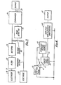
- Figure 1 shows schematically the form of electrical and blood pressure pulses characteristic of a beating heart;
- Figure 2 is a block diagram of components of a device in accordance with the present invention;
- Figure 3 is a block diagram of the electrical pulse sensor of a preferred embodiment of the invention;
- Figure 4 is a block diagram of the pressure pulse sensor of the said embodiment;
- Figure 5 is a graph of fuction Fl; and
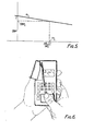
- Figure 6 is a perspective view of the said embodiment.
- Referring to Figure 1, each electrical pulse (R-wave) is identified, as is conventional, with the letters PQRST wherein R identifies the sharp peak of the pulse. The frequency of such pulses is HR. The abscissa of the Figure 1 graph represents time, so the horizontal distance between successive peaks R is 1/HR.
- The
blood pressure pulse 10 shows aperiod 11 of steady pressure q ahead of the pulse, aperiod 12 of rapidly rising pressure and a peak pressure p. One convenient way of determining theinstant 13 of arrival of thepulse 10 is to define it as the instant when the pressure is (p + q)/2. As can be seen from Figure 1, TT is the delay from the instant of the electrical peak R to theconsequent instant 13 of arrival of thepressure pulse 10 at the blood vessel where the pressure is being sensed. - Figure 2 shows how a
signal 20 from an R-wave sensor 21, and a signal 22 from apressure sensor 23, are inputted to amicroprocessor 24, theoutput 25 of which is delivered to a display means 26. - Figure 3 shows the R-
wave sensor 21 in greater detail. A first skin-contact electrode 30 outputs asignal 31 through a three stage band-pass filter 32 and a full-wave rectifier 33 to acomparator 34 and avoltage divider 35. Thedivider 35 inputs apeak detector 36 which provides a second input to thecomparator 34, which generates anoutput signal 37 whenever the instantaneous signal from theelectrode 30 exceeds 0.83 of the magnitude of the average signal from the electrode. Areference electrode 38 provides a reference voltage to thedivider 35. - Figure 4 shows how a light-emitting diode 40 provides
illumination 41 to anarea 42 of skin of the human body being monitored, the intensity ofconsequent illumination 43 of anadjacent phototransistor 44 varying with pressure of blood in vessels immediately below thearea 42 of skin. Theoutput 45 from the transistor is delivered to anamplifier 46 with automatic gain control, and itsoutput 47 inputs themicroprocessor 24. The diode 40,transistor 44 andamplifier 46 are all powered from a stabilisedvoltage source 48. - Figure 5 shows a graph showing the linear variation of DBP with the quantity (HR.TT)/HRc. The gradient m is usually negative and of the order of - 0.06. By measuring an "at rest" heart beat rate HR , and an elapsed time TTc at that instant, one can display an "index" of diastolic blood pressure with the origin DBPc of the index (conveniently displayed as the origin of a bar graph) at the moment of setting the "at rest" rate, and an assumed gradient m of, say, - 0.06 mmHg/ms. Otherwise, one can calibrate the device, to find a real gradient m and intercept I, so allowing measured values of DBP to be displayed.
- Figure 6 shows the device in use. The circuits of Figures 2 to 4 are contained within a casing 60 in which is a display panel 61. A conventional numeric key pad 62 and chronometer keys 63 are provided. The functions of the five other keys, namely, ENTER 64, SET 65, AUDIO/SPLIT 66, MODE 67 and CAL 68 are briefly described below. Within a cuff 69 is a sensing element comprising an LED 40 and
phototransistor 44 arrangement, as shown schematically in Figure 4, for sensing the arrival of pulses of blood pressure in the tip of a digit 70 pressed against the sensing element within the cuff 69. A conductive area 71 on the front of the casing 60 is used to sense ECG R-waves in another digit 72 of the subject. - In use, the MODE key 67 is used to select one of the following modes: CHRONO, PRESSURE INDEX, PRESSURE VALUE. Use in the CHRONO mode is conventional and so will not be described.
- In PRESSURE INDEX (PI) mode, pulse rate HR in beats/minute is displayed in the panel 61, as well as a bar graph showing the magnitude of both systolic and diastolic blood pressures relative to "at rest" values. To input the microprocessor with new "at rest" values, the CAL key 68 is depressed during monitoring. Relative values are computed and displayed on the basis of an assumed value of gradient m.
- The device has an audio output (not shown) which can be actuated by depressing the AUDIO key 66 to signal each heart beat. Furthermore, the SET key 65 can be used to input numerical heart rate minimum and maximum values at which the audio output will sound an alarm. Using this facility an exercise programme can be pursued in which heart rate is maintained within a specified band of elevated heart rates. The function is continued so long as the conductive area 71 receives ECG signals. A digit 70 in the cuff 69 is not needed. By invoking the CHRONO mode a heart beat recovery time can be determined.
- In PRESSURE VALUE (PV) mode, the device requires calibration. For this, the actual heart rate is noted and then, in PV mode, the CAL key 68 is depressed and an "at rest" numerical reference display value noted. Simultaneously, a sphygmomanometer is used to measure absolute values of diastolic and systolic blood pressure. The calibration procedure is repeated immediately following exercise, to obtain equivalent values at a higher heart rate.
- Once these values are established they are inputted to the microprocessor by depressing the SET key 65 and depressing numeral keys as prompted by the display 61. As in the PI mode, specified limit values can be entered which, when reached, cause an audible warning to be emitted.
Claims (13)

wherein
(m, HRc and I all being numerical constants); and further characterised in that the value DBP of Fl is displayed as a value of diastolic blood pressure.

wherein
(m, HRc and I all being numerical constants); and further characterised in that means are provided to display the value of DBP as a value of diastolic blood pressure.
Priority Applications (1)
| Application Number | Priority Date | Filing Date | Title |
|---|---|---|---|
| AT85306390T ATE65683T1 (en) | 1984-09-10 | 1985-09-09 | DEVICE FOR DISPLAYING BLOOD PRESSURE VALUES. |
Applications Claiming Priority (2)
| Application Number | Priority Date | Filing Date | Title |
|---|---|---|---|
| GB8422770 | 1984-09-10 | ||
| GB848422770A GB8422770D0 (en) | 1984-09-10 | 1984-09-10 | Indicating blood pressure |
Publications (3)
| Publication Number | Publication Date |
|---|---|
| EP0181067A2 true EP0181067A2 (en) | 1986-05-14 |
| EP0181067A3 EP0181067A3 (en) | 1987-09-16 |
| EP0181067B1 EP0181067B1 (en) | 1991-07-31 |
Family
ID=10566490
Family Applications (1)
| Application Number | Title | Priority Date | Filing Date |
|---|---|---|---|
| EP85306390A Expired - Lifetime EP0181067B1 (en) | 1984-09-10 | 1985-09-09 | Device for displaying a blood pressure value |
Country Status (5)
| Country | Link |
|---|---|
| EP (1) | EP0181067B1 (en) |
| JP (1) | JPS6168027A (en) |
| AT (1) | ATE65683T1 (en) |
| DE (1) | DE3583653D1 (en) |
| GB (1) | GB8422770D0 (en) |
Cited By (12)
| Publication number | Priority date | Publication date | Assignee | Title |
|---|---|---|---|---|
| WO1989008424A1 (en) * | 1988-03-09 | 1989-09-21 | Vectron Gesellschaft Für Technologieentwicklung Un | Method of continuous measurement of blood pressure in humans |
| FR2704416A1 (en) * | 1993-04-27 | 1994-11-04 | Labadie Dominique | Electronic apparatus for measuring the propagation time of a pulse wave (pulse velocity) |
| WO1998025516A1 (en) * | 1996-10-11 | 1998-06-18 | Dxtek, Inc. | Non-invasive cuffless determination of blood pressure |
| FR2790197A1 (en) | 1999-02-25 | 2000-09-01 | Novamed | System for monitoring arterial pressure using non-invasive means |
| WO2001054575A1 (en) | 2000-01-26 | 2001-08-02 | Vsm Medtech Ltd. | Continuous blood pressure monitoring method and apparatus |
| GB2394178A (en) * | 2002-10-09 | 2004-04-21 | Pulse Time Products Ltd | Method of calibrating a blood pressure monitoring apparatus |
| US6893401B2 (en) | 2001-07-27 | 2005-05-17 | Vsm Medtech Ltd. | Continuous non-invasive blood pressure monitoring method and apparatus |
| USRE38749E1 (en) | 1993-11-12 | 2005-06-28 | Lifewaves International, Inc. | Chronotherapy exercise technique |
| US7013175B2 (en) | 2000-06-30 | 2006-03-14 | Lifewaves International, Inc. | Systems and methods for assessing and modifying an individual's physiological condition |
| US7338410B2 (en) | 2001-04-24 | 2008-03-04 | Lifewaves International Inc. | Systems and methods for breathing exercise regimens to promote ischemic preconditioning |
| CN104720793A (en) * | 2013-12-20 | 2015-06-24 | 日本光电工业株式会社 | Bio-information display device and bio-information display method |
| CN105748051A (en) * | 2016-02-18 | 2016-07-13 | 京东方科技集团股份有限公司 | Blood pressure measuring method and device |
Families Citing this family (5)
| Publication number | Priority date | Publication date | Assignee | Title |
|---|---|---|---|---|
| JPH0627125Y2 (en) * | 1988-10-31 | 1994-07-27 | 株式会社島津製作所 | R wave detection circuit for electrocardiogram |
| DE10249863A1 (en) * | 2002-10-25 | 2004-05-19 | Biosign Gmbh | Non-invasive blood pressure measurement method in which the difference between a signal measured using an impedance cardiograph and that determined using an optical or acoustic peripheral pulse wave is determined |
| DE102005013429A1 (en) * | 2005-03-21 | 2006-09-28 | Flore, Ingo, Dr. | Mobile diagnostic device |
| US9408542B1 (en) | 2010-07-22 | 2016-08-09 | Masimo Corporation | Non-invasive blood pressure measurement system |
| US11576583B2 (en) | 2018-03-27 | 2023-02-14 | Samsung Electronics Co., Ltd. | Noninvasive blood pressure measurement method and device |
Citations (2)
| Publication number | Priority date | Publication date | Assignee | Title |
|---|---|---|---|---|
| EP0021800A2 (en) * | 1979-06-21 | 1981-01-07 | Pulse Time Uk Limited | Cardiovascular monitors |
| US4245648A (en) * | 1978-09-20 | 1981-01-20 | Trimmer Gordon A | Method and apparatus for measuring blood pressure and pulse rate |
-
1984
- 1984-09-10 GB GB848422770A patent/GB8422770D0/en active Pending
-
1985
- 1985-09-09 AT AT85306390T patent/ATE65683T1/en active
- 1985-09-09 DE DE8585306390T patent/DE3583653D1/en not_active Expired - Fee Related
- 1985-09-09 EP EP85306390A patent/EP0181067B1/en not_active Expired - Lifetime
- 1985-09-10 JP JP60200404A patent/JPS6168027A/en active Pending
Patent Citations (2)
| Publication number | Priority date | Publication date | Assignee | Title |
|---|---|---|---|---|
| US4245648A (en) * | 1978-09-20 | 1981-01-20 | Trimmer Gordon A | Method and apparatus for measuring blood pressure and pulse rate |
| EP0021800A2 (en) * | 1979-06-21 | 1981-01-07 | Pulse Time Uk Limited | Cardiovascular monitors |
Cited By (19)
| Publication number | Priority date | Publication date | Assignee | Title |
|---|---|---|---|---|
| WO1989008424A1 (en) * | 1988-03-09 | 1989-09-21 | Vectron Gesellschaft Für Technologieentwicklung Un | Method of continuous measurement of blood pressure in humans |
| FR2704416A1 (en) * | 1993-04-27 | 1994-11-04 | Labadie Dominique | Electronic apparatus for measuring the propagation time of a pulse wave (pulse velocity) |
| USRE38749E1 (en) | 1993-11-12 | 2005-06-28 | Lifewaves International, Inc. | Chronotherapy exercise technique |
| USRE40401E1 (en) | 1993-11-12 | 2008-06-24 | Lifewaves International, Inc. | Therapeutic exercise program |
| WO1998025516A1 (en) * | 1996-10-11 | 1998-06-18 | Dxtek, Inc. | Non-invasive cuffless determination of blood pressure |
| FR2790197A1 (en) | 1999-02-25 | 2000-09-01 | Novamed | System for monitoring arterial pressure using non-invasive means |
| WO2001054575A1 (en) | 2000-01-26 | 2001-08-02 | Vsm Medtech Ltd. | Continuous blood pressure monitoring method and apparatus |
| US6599251B2 (en) | 2000-01-26 | 2003-07-29 | Vsm Medtech Ltd. | Continuous non-invasive blood pressure monitoring method and apparatus |
| US7013175B2 (en) | 2000-06-30 | 2006-03-14 | Lifewaves International, Inc. | Systems and methods for assessing and modifying an individual's physiological condition |
| US7054678B2 (en) | 2000-06-30 | 2006-05-30 | Lifewaves International, Inc. | Systems and methods for assessing and modifying an individual's physiological condition |
| US7151959B2 (en) | 2000-06-30 | 2006-12-19 | Lifewaves International, Inc. | Systems and methods for assessing and modifying an individual's physiological condition |
| US7228168B2 (en) | 2000-06-30 | 2007-06-05 | Lifewaves International, Inc. | Systems and methods for assessing and modifying an individual's physiological condition |
| US7338410B2 (en) | 2001-04-24 | 2008-03-04 | Lifewaves International Inc. | Systems and methods for breathing exercise regimens to promote ischemic preconditioning |
| US6893401B2 (en) | 2001-07-27 | 2005-05-17 | Vsm Medtech Ltd. | Continuous non-invasive blood pressure monitoring method and apparatus |
| GB2394178A (en) * | 2002-10-09 | 2004-04-21 | Pulse Time Products Ltd | Method of calibrating a blood pressure monitoring apparatus |
| GB2394178B (en) * | 2002-10-09 | 2005-12-07 | Pulse Time Products Ltd | Method of calibrating a blood pressure monitoring apparatus |
| CN104720793A (en) * | 2013-12-20 | 2015-06-24 | 日本光电工业株式会社 | Bio-information display device and bio-information display method |
| CN105748051A (en) * | 2016-02-18 | 2016-07-13 | 京东方科技集团股份有限公司 | Blood pressure measuring method and device |
| CN105748051B (en) * | 2016-02-18 | 2018-10-09 | 京东方科技集团股份有限公司 | A kind of blood pressure measuring device |
Also Published As
| Publication number | Publication date |
|---|---|
| EP0181067B1 (en) | 1991-07-31 |
| GB8422770D0 (en) | 1984-10-17 |
| ATE65683T1 (en) | 1991-08-15 |
| DE3583653D1 (en) | 1991-09-05 |
| EP0181067A3 (en) | 1987-09-16 |
| JPS6168027A (en) | 1986-04-08 |
Similar Documents
| Publication | Publication Date | Title |
|---|---|---|
| US4869262A (en) | Device for displaying blood pressure | |
| EP0181067B1 (en) | Device for displaying a blood pressure value | |
| US4854327A (en) | Non-invasive and continuous cardiac performance monitoring device | |
| US5558096A (en) | Blood pulse detection method using autocorrelation | |
| US4367752A (en) | Apparatus for testing physical condition of a subject | |
| US4120294A (en) | Electrode system for acquiring electrical signals from the heart | |
| US6599251B2 (en) | Continuous non-invasive blood pressure monitoring method and apparatus | |
| EP0498885B1 (en) | A method of measuring blood pressure with a photoplethysmograph | |
| EP0479947B1 (en) | Non-invasive cardiac performance monitoring device and method | |
| US4759369A (en) | Pulse oximeter | |
| KR100871230B1 (en) | Method and?apparatus for the cuffless and non-invasive device connected to communication device which measures blood pressure from a wrist | |
| US5755229A (en) | Pulse wave analysis device | |
| US5241966A (en) | Method and apparatus for measuring cardiac output | |
| US4907596A (en) | Blood pressure measuring appliance | |
| US6893401B2 (en) | Continuous non-invasive blood pressure monitoring method and apparatus | |
| US4566463A (en) | Apparatus for automatically measuring blood pressure | |
| US6083171A (en) | Blood pressure monitoring apparatus | |
| EP1369082A2 (en) | Physical activity measurement apparatus | |
| EP0024772A1 (en) | Apparatus for measuring the human being's blood pressure | |
| US5840039A (en) | Method and apparatus in connection with measuring the heartbeat rate of a person | |
| US11039795B2 (en) | Physiological monitoring and related methods | |
| JPH10184A (en) | Motion intensity measuring device | |
| EP0160994A2 (en) | Heart-related parameters monitoring apparatus | |
| JP2012095795A (en) | Pulse wave analysis method | |
| EP0419103A1 (en) | Pulsimeter |
Legal Events
| Date | Code | Title | Description |
|---|---|---|---|
| PUAI | Public reference made under article 153(3) epc to a published international application that has entered the european phase |
Free format text: ORIGINAL CODE: 0009012 |
|
| AK | Designated contracting states |
Kind code of ref document: A2 Designated state(s): AT BE CH DE FR GB IT LI NL SE |
|
| PUAL | Search report despatched |
Free format text: ORIGINAL CODE: 0009013 |
|
| AK | Designated contracting states |
Kind code of ref document: A3 Designated state(s): AT BE CH DE FR GB IT LI NL SE |
|
| 17P | Request for examination filed |
Effective date: 19880128 |
|
| 17Q | First examination report despatched |
Effective date: 19891115 |
|
| GRAA | (expected) grant |
Free format text: ORIGINAL CODE: 0009210 |
|
| AK | Designated contracting states |
Kind code of ref document: B1 Designated state(s): AT BE CH DE FR GB IT LI NL SE |
|
| PG25 | Lapsed in a contracting state [announced via postgrant information from national office to epo] |
Ref country code: SE Effective date: 19910731 Ref country code: NL Effective date: 19910731 Ref country code: LI Effective date: 19910731 Ref country code: IT Free format text: LAPSE BECAUSE OF FAILURE TO SUBMIT A TRANSLATION OF THE DESCRIPTION OR TO PAY THE FEE WITHIN THE PRESCRIBED TIME-LIMIT;WARNING: LAPSES OF ITALIAN PATENTS WITH EFFECTIVE DATE BEFORE 2007 MAY HAVE OCCURRED AT ANY TIME BEFORE 2007. THE CORRECT EFFECTIVE DATE MAY BE DIFFERENT FROM THE ONE RECORDED. Effective date: 19910731 Ref country code: CH Effective date: 19910731 Ref country code: BE Effective date: 19910731 Ref country code: AT Effective date: 19910731 |
|
| REF | Corresponds to: |
Ref document number: 65683 Country of ref document: AT Date of ref document: 19910815 Kind code of ref document: T |
|
| REF | Corresponds to: |
Ref document number: 3583653 Country of ref document: DE Date of ref document: 19910905 |
|
| ET | Fr: translation filed | ||
| REG | Reference to a national code |
Ref country code: CH Ref legal event code: PL |
|
| NLV1 | Nl: lapsed or annulled due to failure to fulfill the requirements of art. 29p and 29m of the patents act | ||
| PLBE | No opposition filed within time limit |
Free format text: ORIGINAL CODE: 0009261 |
|
| STAA | Information on the status of an ep patent application or granted ep patent |
Free format text: STATUS: NO OPPOSITION FILED WITHIN TIME LIMIT |
|
| 26N | No opposition filed | ||
| PGFP | Annual fee paid to national office [announced via postgrant information from national office to epo] |
Ref country code: FR Payment date: 19930825 Year of fee payment: 9 |
|
| PG25 | Lapsed in a contracting state [announced via postgrant information from national office to epo] |
Ref country code: FR Effective date: 19950531 |
|
| REG | Reference to a national code |
Ref country code: FR Ref legal event code: ST |
|
| PGFP | Annual fee paid to national office [announced via postgrant information from national office to epo] |
Ref country code: DE Payment date: 20011116 Year of fee payment: 17 |
|
| REG | Reference to a national code |
Ref country code: GB Ref legal event code: IF02 |
|
| PG25 | Lapsed in a contracting state [announced via postgrant information from national office to epo] |
Ref country code: DE Free format text: LAPSE BECAUSE OF NON-PAYMENT OF DUE FEES Effective date: 20030401 |
|
| PGFP | Annual fee paid to national office [announced via postgrant information from national office to epo] |
Ref country code: GB Payment date: 20040824 Year of fee payment: 20 |
|
| PG25 | Lapsed in a contracting state [announced via postgrant information from national office to epo] |
Ref country code: GB Free format text: LAPSE BECAUSE OF EXPIRATION OF PROTECTION Effective date: 20050908 |
|
| REG | Reference to a national code |
Ref country code: GB Ref legal event code: PE20 |