EP0180532A1 - Coaptor for fractured femoral necks and the like - Google Patents
Coaptor for fractured femoral necks and the like Download PDFInfo
- Publication number
- EP0180532A1 EP0180532A1 EP85460016A EP85460016A EP0180532A1 EP 0180532 A1 EP0180532 A1 EP 0180532A1 EP 85460016 A EP85460016 A EP 85460016A EP 85460016 A EP85460016 A EP 85460016A EP 0180532 A1 EP0180532 A1 EP 0180532A1
- Authority
- EP
- European Patent Office
- Prior art keywords
- barrel
- fin
- coaptor
- axis
- rod
- Prior art date
- Legal status (The legal status is an assumption and is not a legal conclusion. Google has not performed a legal analysis and makes no representation as to the accuracy of the status listed.)
- Granted
Links
Images
Classifications
-
- A—HUMAN NECESSITIES
- A61—MEDICAL OR VETERINARY SCIENCE; HYGIENE
- A61B—DIAGNOSIS; SURGERY; IDENTIFICATION
- A61B17/00—Surgical instruments, devices or methods, e.g. tourniquets
- A61B17/56—Surgical instruments or methods for treatment of bones or joints; Devices specially adapted therefor
- A61B17/58—Surgical instruments or methods for treatment of bones or joints; Devices specially adapted therefor for osteosynthesis, e.g. bone plates, screws, setting implements or the like
- A61B17/68—Internal fixation devices, including fasteners and spinal fixators, even if a part thereof projects from the skin
- A61B17/74—Devices for the head or neck or trochanter of the femur
- A61B17/742—Devices for the head or neck or trochanter of the femur having one or more longitudinal elements oriented along or parallel to the axis of the neck
- A61B17/746—Devices for the head or neck or trochanter of the femur having one or more longitudinal elements oriented along or parallel to the axis of the neck the longitudinal elements coupled to a plate opposite the femoral head
Definitions
- the present invention relates to a device for anchoring fractures of the neck of the femur or similar fractures, called a coaptor.
- a gallows-shaped anchoring device In known osteosynthesis techniques for the neck of the femur, a gallows-shaped anchoring device is generally used. This comprises an elongated, curved plate, intended to be fixed by means of screws to the upper part of the femoral shaft, and a shaft which forms an obtuse angle with the plate and which is intended to be inserted into the femoral epiphysis across the cervical fracture.
- the barrel includes a threaded pin which can be screwed into the fractured epiphysis so as to achieve a certain compression of the disjointed parts against each other.
- a threaded pin which can be screwed into the fractured epiphysis so as to achieve a certain compression of the disjointed parts against each other.
- the invention solves these problems by proposing a coaptor, that is to say a device for anchoring fractures of the neck of the femur, which allows effective and controlled compression of the disjointed parts, while being simple to install, resistant, and a low cost price.
- the device which is the subject of the present invention comprises, like the known devices, an elongated plate intended to be fixed to the femoral diaphysis. and a substantially cylindrical barrel intended to be housed in a bore crossing the neck of the fractured femur, the barrel and the plate being connected by their ends at an obtuse angle.
- the barrel is provided with a cutting fin which is situated at the end of the barrel opposite the plate and is arranged transversely with respect to the axis of the barrel, this fin pivoting about an axis which is slightly offset being pivotally mounted about an axis which is slightly offset from the axis of the barrel.
- the pivot axis of the fin can be offset angularly and / or laterally with respect to the axis of the barrel.
- the fin is advantageously movable in translation in the direction of the plate; it is thus possible to compress, by means of the fin, the separate parts, in a controlled and adjustable manner.
- the fin is carried by a rod mounted in rotation and with longitudinal sliding in the barrel, and the opposite end of which is threaded, the displacement of the fin in translation is then achieved by screwing d 'a nut on this threaded end, the nut pressing against the corresponding end of the barrel.
- the shape of the fin is advantageously circular, with a diameter close to that of the barrel.
- the fin may also have the shape of a blade. By giving it a helical shape, it is possible to obtain an improved anchoring of the device in the bone tissue because, during its rotation, the fin causes the head of the femur to move against the trochanter, achieving the desired compression of the disjoint parts.
- the barrel is preferably provided with peripheral longitudinal ribs which ensure its immobilization in rotation during the operation. It also optionally has a longitudinal groove capable of guiding it by a spindle when it is put in place.
- the latter includes the trochanter 3, the neck 4 and the head 5.
- the parts 3 and 5 are separated at the level of the neck by a fracture 6 which it is proposed to resolder by osteosynthesis.
- the osteosynthesis device has the form of a bracket which comprises an elongated plate 7 and a cylindrical barrel 8 forming integral parts of one another.
- the device is made of metal, for example stainless steel or high-strength plastic.
- the plate 7 has a curved section, as seen in Figure 2, adapted to fit at least approximately the upper lateral lateral part of the femoral epiphysis. It has several holes, for example three holes 9, for the passage of fixing screws 10.
- the barrel 8 forms with the plate 7 an obtuse angle, of the order of 135 ° for example. Its wall is provided with a pair of longitudinal ribs 11, preferably with a tapered edge, which extend over at least part of its length.
- the barrel 8 is pierced by a cylindrical bore 12 whose axis X 1 is angularly offset relative to the axis X o of the barrel.
- This angular offset by a few degrees, is such that the center of the bore 12 approximately coincides with the center of the barrel 8 at its end situated on the side of the plate 7 (on the left of the figures), and is substantially offset laterally- for example down - relative to the center of the barrel at its other end (on the right of the figures).
- the bore 12 opens into a bore 13 of larger diameter.
- a rod 14 In the bore 12 is mounted a rod 14, of corresponding diameter, one of the ends 15 of which protrudes into the bore 13 and the other end 16 projects beyond the front face 17 of the barrel 8.
- the end 16 carries a disc-shaped fin 18 with a cutting edge whose diameter is close to that of the face 17.
- the disc 18 forms an integral part of the rod 14 or, on the contrary, is attached to it by any suitable means such as welding, riveting or screwing.
- the center of the disc 18 is eccentric with respect to the center of the face 17 by a value which corresponds to the decentralization of the axes X 1 and X at this location.
- the end 15 is crossed by a pin 19 and has a threaded part 20, of the same diameter as the rod 14, which protrudes from the outer edge 21 of the barrel 8.
- the anchoring tool shown in FIGS. 8 and 9, consists of a cylindrical sleeve 22 crossed by an operating rod 23.
- the outside diameter of the sleeve 22 is slightly less than that of the bore 13. Its inside diameter is slightly higher than that of the rod 14 and of the threaded part 20.
- the sleeve is milled radially so as to have two longitudinal slots 24. These are situated at the end opposite to that which carries the operating rod 23.
- a spindle is introduced through the trochanter, the neck and the head of the femur and a bore 26 of diameter equal or slightly greater than that of the barrel 8 is drilled, coaxially with the spindle, using the latter as the member guide. It is a blind bore, the length of which is slightly greater than that of the barrel 8.
- the hole drilled by the pin is designated by the reference 25 in the drawings.
- the spindle is removed and the barrel 8 is introduced into the bore 26 until the plate 7 is pressed against the external lateral edge of the upper part of the femoral shaft.
- the discoid fin 18 is located exactly opposite the front part 17 of the barrel 8, against the latter.
- the lateral ribs 11 of the barrel are housed in the surrounding bone tissue during the insertion of the barrel into the hole 26.
- the plate 7 is fixed to the femoral shaft by means of the screws 10, and is pushed on the rod 14 to detach the fin 18 from the front face 17 by a certain distance D; this distance is a few millimeters, for example 5 mm.
- the sleeve 22 of the anchoring tool is engaged on the end 15 of the rod 14 so that the slots 24 surround the projecting ends of the pin 19.
- the surgeon rotates this tool d 'a half-turn by means of the handle 23, which causes the corresponding rotation, in the manner of a latch, of the cutting disc 18.
- the latter penetrates into the cancellous bone which surrounds it.
- the ribs 11 prevent the barrel from also rotating during the rotation of the disc.
- the anchoring is very effective and the bone tissue remains healthy on both sides of the disc. This situation is illustrated in Figure 3.
- the anchoring tool is removed and a nut 27 is screwed, possibly via a locking washer 28, onto the threaded part 20 of the rod 14.
- the nut 27 - or possibly the washer 28 - bears against the face 21 of the barrel 8 and traction is carried out on the rod 14.
- the latter slides in the direction of the plate 7; the discoid fin 18 compresses the bone tissue 30 located opposite, and causes displacement, then intimate contact, of the femur head 5 with the trochanter 3 at the fracture.
- This longitudinal movement of the rod 14 and the fin 18 is possible due to the existence of the initial clearance D between this fin and the front face 17 of the barrel 8.
- the amplitude of this movement can be adjusted by the surgeon in depending on the type of fracture and the quality of the bone tissue.
- a new osteosynthesis device can be used, with a slightly shorter barrel length because the bone tissue of the head of the femur has not been damaged, unlike what happens with the usual screw systems (which then play the role of cookie cutter).
- Precose support after operation should be possible on the one hand due to the high resistance to bending of the stem constituted by the metal plate and the barrel (whose diameter is relatively large), and on the other hand of the anchor.
- the device shown in Figures 9 to 12, comprises a curved plate 31 and a barrel 32 of axis X 0 forming an obtuse angle with said wafer.
- the barrel 32 On the top of the barrel 32 is formed a longitudinal groove 33; the barrel 32 is provided with lateral ribs 34 similar to the ribs 11 of the device described above.
- the barrel 32 is pierced with a bore 35 whose axis X 2 is parallel but offset downward relative to the axis X.
- a rod 36 which is provided at its internal end (intended to be housed in the femoral epiphysis) with a blade-shaped cutting fin 37.
- the rod 36 has a threaded portion 38 of which the front face has a hexagonal imprint 39.
- the lower edge 40 of the internal end of the bore 35 is indented, the material having been removed there.
- This device is set up in a similar manner to that described above for the first embodiment.
- the groove 33 allows the barrel 32 to be guided by means of a pin previously inserted into the femoral epiphysis (not shown).
- the rotation of the blade 37 is controlled by means of an awning key which is introduced into the cavity 39; after a half-turn the blade 37 protrudes downwards due to the offset of the axes X and X 2 ( Figures 10 and 12); the axial displacement of the rod 36 is obtained, as in the previous embodiment, by means of a nut which is screwed onto the threaded part 38. This displacement is authorized by the presence of the notch 40 which does not contradict not the longitudinal movement of the blade 37 ( Figure 11).
- FIG. 13 shows (partially) a third embodiment of a device according to the invention.
- This device comprises a barrel 41, of axis X, similar to those previously described. It comprises a fin 42 carried by a shaft 43 guided in rotation in the barrel 41.
- the axis X3 of the shaft 43 is offset either angularly, or laterally, or both angularly and laterally, relative to the axis X .
- the blade 32, and in particular its cutting edge 44 have a helical shape.
- the rod 43 After placing this device in the femoral epiphysis, the rod 43 is rotated by half a turn; the cutting edge then bites into the surrounding bone tissue and, due to its helical shape, causes the head of the femur to move towards the neck. The desired compression is thus achieved without a longitudinal displacement of the rod 43 being necessary.
- the barrel is then formed of two sections of different diameters; the diameter of the internal section (on the side of the fin) is slightly smaller than the diameter of the external section (on the side of the elongated plate). This arrangement avoids having to drill too large a bore in the head of the femur, and possibly in the cervix in the vicinity of the fracture, the bone tissue being generally fragile in these regions.
Abstract
Description
La présente invention concerne un dispositif d'ancrage des fractures du col du fémur ou de fractures similaires, appelé coapteur.The present invention relates to a device for anchoring fractures of the neck of the femur or similar fractures, called a coaptor.
Dans les techniques d'ostéosynthèse du col du fémur connues, on utilise généralement un dispositif d'ancrage en forme de potence. Celle-ci comprend une plaque allongée, galbée, destiné à être fixée au moyen de vis à la partie supérieure de la diaphyse fémorale, et un fût qui forme un angle obtus avec la plaque et qui est destiné à être enfoncé dans l'épiphyse fémorale à travers la fracture du col.In known osteosynthesis techniques for the neck of the femur, a gallows-shaped anchoring device is generally used. This comprises an elongated, curved plate, intended to be fixed by means of screws to the upper part of the femoral shaft, and a shaft which forms an obtuse angle with the plate and which is intended to be inserted into the femoral epiphysis across the cervical fracture.
Certains dispositifs, dans lesquels le fût a simplement la forme d'un clou, n'assurent pas la compression des deux parties disjointes l'une contre l'autre.Certain devices, in which the barrel is simply in the form of a nail, do not ensure the compression of the two disjointed parts one against the other.
Dans d'autres dispositifs, le fût comprend une broche filetée qui peut être vissée dans l'épiphyse fracturée de manière à réaliser une certaine compression des parties disjointes l'une contre l'autre. Malheureusement, l'expérience a montré que la pose de cette broche se révèle problèmatique en raison du risque d'une détérioration de l'os spongieux par les filets de la broche. Un dispositif de ce genre est connu par exemple par le document FR-A- 2 342 710.In other devices, the barrel includes a threaded pin which can be screwed into the fractured epiphysis so as to achieve a certain compression of the disjointed parts against each other. Unfortunately, experience has shown that the installation of this pin is problematic due to the risk of damage to the cancellous bone by the threads of the pin. A device of this kind is known, for example, from the document FR-A-2 342 710.
L'invention résoud ces problèmes en proposant un coapteur, c'est-à-dire un dispositif d'ancrage des fractures du col du fémur, qui permette une compression efficace et contrôlée des parties disjointes, tout en étant simple à poser, résistant, et d'un prix de revient faible.The invention solves these problems by proposing a coaptor, that is to say a device for anchoring fractures of the neck of the femur, which allows effective and controlled compression of the disjointed parts, while being simple to install, resistant, and a low cost price.
A cet effet, le dispositif objet de la présente invention comprend, comme les dispositifs connus, une plaque allongée destinée à être fixée à la diaphyse fémorale et un fût sensiblement cylindrique destiné à être logé dans un alésage traversant le col du fémur fracturé, le fût et la plaque étant reliés par leurs extrémités en formant un angle obtus. Conformément à l'invention, le fût est pourvu d'une ailette coupante qui est située à l'extrémité du fût opposée à la plaque et est disposée transversalement par rapport à l'axe du fût,,cette ailette pivotement autour d'un axe qui est légèrement décalé étant montée à pivotement autour d'un axe qui est légèrement décalé par rapport a l'axe du fut.To this end, the device which is the subject of the present invention comprises, like the known devices, an elongated plate intended to be fixed to the femoral diaphysis. and a substantially cylindrical barrel intended to be housed in a bore crossing the neck of the fractured femur, the barrel and the plate being connected by their ends at an obtuse angle. According to the invention, the barrel is provided with a cutting fin which is situated at the end of the barrel opposite the plate and is arranged transversely with respect to the axis of the barrel, this fin pivoting about an axis which is slightly offset being pivotally mounted about an axis which is slightly offset from the axis of the barrel.
Ainsi, en mettant l'ailette en correspondance avec l'extrémité du fût, il est possible de mettre en place le dispositif en faisant tourner l'ailette d'un angle maximal de 180°, on la décale par rapport à l'extrémité du fût en la faisant pénétrer dans le tissu osseux avoisinant.Thus, by putting the fin in correspondence with the end of the barrel, it is possible to set up the device by rotating the fin by a maximum angle of 180 °, it is offset relative to the end of the barrel. was by making it penetrate into the surrounding bone tissue.
L'axe de pivotement de l'ailette peut être décalé angulairement et/ou latéralement par rapport à l'axe du fût.The pivot axis of the fin can be offset angularly and / or laterally with respect to the axis of the barrel.
L'ailette est avantageusement mobile en translation en direction de la plaque ; il est ainsi possible de comprimer,au moyen de l'ailette, les parties disjointes, de manière contrôlée et réglable. Dans une forme de réalisation préférentielle du dispositif, l'ailette est portée par une tige montée à rotation et à coulissement longitudinal dans le fût, et dont l'extrémité opposée est filetée le déplacement de l'ailette en translation est alors réalisé par vissage d'un écrou sur cette extrémité filetée, l'écrou prenant appui contre l'extrémité correspondante du fût.The fin is advantageously movable in translation in the direction of the plate; it is thus possible to compress, by means of the fin, the separate parts, in a controlled and adjustable manner. In a preferred embodiment of the device, the fin is carried by a rod mounted in rotation and with longitudinal sliding in the barrel, and the opposite end of which is threaded, the displacement of the fin in translation is then achieved by screwing d 'a nut on this threaded end, the nut pressing against the corresponding end of the barrel.
La forme de l'ailette est avantageusement circulaire, de diamètre voisin de celui du fût.The shape of the fin is advantageously circular, with a diameter close to that of the barrel.
L'ailette peut également avoir une forme de pale. En donnant à celle-ci une forme hélicoidale, il est possible d'obtenir un ancrage amélioré du dispositif dans le tissu osseux car, au cours de sa rotation, l'ailette provoque le déplacement de la tête du fémur contre le trochanter, réalisant la compression souhaitée des parties disjointes.The fin may also have the shape of a blade. By giving it a helical shape, it is possible to obtain an improved anchoring of the device in the bone tissue because, during its rotation, the fin causes the head of the femur to move against the trochanter, achieving the desired compression of the disjoint parts.
Le fût est muni de préférence de nervures longinales périphériques qui assurent son immobilisation en rotation au cours de l'opération. Il présente également, éventuellement, une rainure longitudinale apte à assurer son guidage par une broche lors de sa mise en place.The barrel is preferably provided with peripheral longitudinal ribs which ensure its immobilization in rotation during the operation. It also optionally has a longitudinal groove capable of guiding it by a spindle when it is put in place.
D'autres particularités et avantages de l'invention apparaîtront de la description et des dessins annnexés qui présentent des modes de réalisation préférentiels de l'invention.Other features and advantages of the invention will become apparent from the description and the appended drawings which show preferred embodiments of the invention.
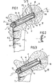
- La figure 1 représente, en vue de face coupée, une première forme de réalisation du dispositif selon l'invention mis en place dans une épiphyse fémorale fracturée, avant ancrage ;Figure 1 shows, in cutaway view, a first embodiment of the device according to the invention implemented in a fractured femoral epiphysis, before anchoring;
- La figure 2 est une section d'une partie du dispositif, coupé par le plan II de la figure 1 ;Figure 2 is a section of part of the device, cut by the plane II of Figure 1;
- La figure 3 est une vue analogue à la figure 1 montrant le dispositif après ancrage mais avant compression ;Figure 3 is a view similar to Figure 1 showing the device after anchoring but before compression;
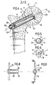
- La figure 4 est une vue analogue aux figures 1 et 3 montrant le dispositif après compression ;Figure 4 is a view similar to Figures 1 and 3 showing the device after compression;
- Les figures 5 et 6 sont des vues en bout du dispositif, vues selon les plans V et VI des figures 1 et 3 respectivement ;Figures 5 and 6 are end views of the device, seen along planes V and VI of Figures 1 and 3 respectively;
- La figure 7 est une vue de côté d'un outil d'ancrage apte à actionner le dispositif des figures 1 à 6 ;Figure 7 is a side view of an anchoring tool capable of actuating the device of Figures 1 to 6;
- La figure 8 est une vue de face de cet outil coupé par le plan VIII-VIII de la figure 7 ;Figure 8 is a front view of this tool cut by the plane VIII-VIII of Figure 7;
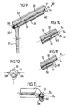
- La figure 9 représente,en vue de face coupée, une seconde forme de réalisation d'un dispositif conforme à l'invention, après mise en place dans une épiphyse fémorale (non représentée) ;FIG. 9 represents, in cut away view, a second embodiment of a device according to the invention, after placement in a femoral epiphysis (not shown);
- Les figures 10 et 11 sont des vues partielles analogues à la figure 9 montrant le dispositif respectivement après ancrage et après compression ;Figures 10 and 11 are partial views similar to Figure 9 showing the device respectively after anchoring and after compression;
- La figure 12 est une vue en bout du dispositif de la figure 9, vu suivant la flèche XII ;Figure 12 is an end view of the device of Figure 9, seen along arrow XII;
- La figure 13 est une vue en perspective de l'extrémité d'une troisième forme de réalisation d'un dispositif conforme à l'invention.Figure 13 is a perspective view of the end of a third embodiment of a device according to the invention.
-
La figure 1 représente l'extrémité supérieure d'un fémur, qui comprend la diaphyse 1 et l'épiphyse 2.Figure 1 shows the upper end of a femur, which includes the shaft 1 and the
epiphysis 2.
Cette dernière comprend le trochanter 3, le col 4 et la tête 5. Les parties 3 et 5 sont disjointes au niveau du col par une fracture 6 que l'on se propose de ressouder par ostéosynthèse.The latter includes the trochanter 3, the
Le dispositif d'ostéosynthèse a la forme d'une potence qui comprend une plaque allongée 7 et un fût cylindrique 8 formant parties intégrantes l'une de l'autre. Le dispositif est en métal, par exemple en acier inoxydable ou en matière plastique à haute résistance.The osteosynthesis device has the form of a bracket which comprises an elongated plate 7 and a
La plaque 7 a une section incurvée, comme on le voit sur la figure 2, adaptée pour épouser au moins approximativement la partie supérieure latérale externe de l'épiphyse fémorale. Elle comporte plusieurs trous, par exemple trois trous 9, pour le passage de vis de fixation 10.The plate 7 has a curved section, as seen in Figure 2, adapted to fit at least approximately the upper lateral lateral part of the femoral epiphysis. It has several holes, for example three
Le fût 8 forme avec la plaque 7 un angle obtus, de l'ordre de 135° par exemple. Sa paroi est pourvue d'une paire de nervures longitudinales 11, de préférence à bord effilé, qui s'étendent sur une partie au moins de sa longueur.The
Le fût 8 est percé par un alésage cylindrique 12 dont l'axe X1 est décalé angulairement par rapport à l'axe Xo du fût. Ce décalage angulaire, de quelques degrés, est tel que le centre de l'alésage 12 coincide approximativement avec le centre du fût 8 à son extrémité située du côté de la plaque 7 (sur la gauche des figures), et soit sensiblement déporté latéralement-par exemple vers le bas - par rapport au centre du fût à son autre extrémité (sur la droite des figures). A l'extrémité située du côté de la plaque 7, l'alésage 12 débouche dans un alésage 13 de plus grand diamètre.The
Dans l'alésage 12 est montée une tige 14, de diamètre correspondant dont l'une des extrémités 15 fait saillie dans l'alésage 13 et l'autre extrémité 16 fait saillie au delà de la face frontale 17 du fût 8.In the
L'extrémité 16 porte une ailette en forme de disque 18 à bord coupant dont le diamètre est voisin de celui de la face 17. Le disque 18 forme partie intégrante de la tige 14 ou, au contraire, est rapporté sur celle-ci par tout moyen approprié tel que soudage, rivetage ou vissage. Le centre du disque 18 est excentré par rapport au centre de la face 17 d'une valeur qui correspond au décentrage des axes X1 et X en cet endroit.The
L'extrémité 15 est traversé par une goupille 19 et présente une partie filetée 20, de même diamètre que la tige 14, qui dépasse du bord extérieur 21 du fût 8.The
L'outil d'ancrage,représenté aux figures 8 et 9, est constitué par une manchon cylindrique 22 traversé par une tige de manoeuvre 23. Le diamètre extérieur du manchon 22 est légèrement inférieur à celui de l'alésage 13. Son diamètre intérieur est légèrement supérieur à celui de la tige 14 et de la partie filetée 20. Le manchon est fraisé radialement de manière à présenter deux lumières longitudinales 24. Celles-ci sont situées à l'extrémité opposée à celle qui porte la tige de manoeuvre 23.The anchoring tool, shown in FIGS. 8 and 9, consists of a
Nous allons maintenant décrire la manière dont on utilise ce dispositif dans une opération d'ostéosynthèse du col du fémur 4.We will now describe the way in which this device is used in an osteosynthesis operation of the
On introduit, de manière connue, une broche à travers le trochanter, le col et la tête du fémur et on perce un alésage 26 de diamètre égal ou légèrement supérieur à celui du fût 8, coaxialement à la broche, en utilisant cette dernière comme organe de guidage. Il s'agit d'un alésage borgne, dont la longueur est légèrement supérieure à celle du fût 8.In a known manner, a spindle is introduced through the trochanter, the neck and the head of the femur and a
Le trou percé par la broche est désigné par la référence 25 sur les dessins.The hole drilled by the pin is designated by the
Après perçage, on retire la broche et on introduit le fût 8 dans l'alésage 26 jusqu'à ce que la plaque 7 s'applique contre le bord latéral externe de la partie supérieure de la diaphyse fémorale. Durant cette introduction, l'ailette discoide 18 se trouve exactement en vis-à-vis de la partie frontale 17 du fût 8, contre celle-ci.After drilling, the spindle is removed and the
Les nervures latérales 11 du fût se logent dans le tissu osseux avoisinant au cours de l'enfoncement du fût dans le trou 26.The
Ensuite, on fixe la plaque 7 à la diaphyse fémorale au moyen des vis 10, et on pousse sur la tige 14 pour décoller l'ailette 18 de la face frontale 17 d'une certaine distance D ; cette distance est de quelques millimètres, par exemple de 5 mm. Puis on engage le manchon 22 de l'outil d'ancrage sur l'extrémité 15 de la tige 14 de telle sorte que les lumières 24 viennent entourer les extrémités en 'saillie de la goupille 19. Ensuite, le chirurgien fait tourner cet outil d'un demi-tour au moyen de la poignée 23, ce qui entraîne la rotation correspondante, à la manière d'un loquet, du disque coupant 18. Ce dernier pénètre dans l'os spongieux qui l'entoure. Les nervures 11 empêchent que le fût ne tourne lui aussi durant la rotation du disque. L'ancrage est très efficace et le tissu osseux reste sain de part et d'autre du disque. Cette situation est illustrée à la figure 3.Then, the plate 7 is fixed to the femoral shaft by means of the
Ensuite, on retire l'outil d'ancrage et on visse un écrou 27, éventuellement par l'intermédiaire d'une rondelle de blocage 28, sur la partie filetée 20 de la tige 14. Durant ce vissage, l'écrou 27 - ou éventuellement la rondelle 28 - prend appui contre la face 21 du fût 8 et on réalise une traction sur la tige 14. Celle-ci coulisse en direction de la plaque 7 ; l'ailette discoïde 18 comprime le tissu osseux 30 situé en vis-à-vis, et provoque le déplacement, puis le contact intime, de la tête de fémur 5 avec le trochanter 3 au niveau de la fracture. Ce mouvement longitudinal de la tige 14 et de l'ailette 18 est possible du fait de l'existence du jeu initial D entre cette ailette et la face frontale 17 du fût 8. L'amplitude de ce mouvement peut être réglé par le chirurgien en fonction du type de la fracture et de la qualité du tissu osseux.Then, the anchoring tool is removed and a
En cas de bris au niveau de l'ailette, ou d'incidents divers, un démontage est toujours possible. De plus, on peut utiliser un nouveau dispositif d'ostéosynthèse, de longueur de fût un peu plus courte car le tissu osseux de la tête du fémur n'a pas été détérioré contrairement à ce qui se passe avec les systèmes à vis habituels (qui jouent alors le rôle d'emporte-pièce).In the event of breakage at the level of the fin, or various incidents, disassembly is always possible. In addition, a new osteosynthesis device can be used, with a slightly shorter barrel length because the bone tissue of the head of the femur has not been damaged, unlike what happens with the usual screw systems (which then play the role of cookie cutter).
L'appui précose après opération devrait être possible en raison d'une part de la grande résistance à la flexion de la potence constituée par la plaque métallique et le fût (dont le diamètre est relativement grand), et d'autre part de la qualité de l'ancrage.Precose support after operation should be possible on the one hand due to the high resistance to bending of the stem constituted by the metal plate and the barrel (whose diameter is relatively large), and on the other hand of the anchor.
On notera qu'il est possible d'intervenir sur la compression en agissant sur la vis, même en cours de service. Par ailleurs, le dispositif est démontable ; il suffit pour cela de reprendre les opérations précédentes dans l'ordre inverse.Note that it is possible to intervene on the compression by acting on the screw, even during service. Furthermore, the device is removable; it is enough to do this, repeat the previous operations in reverse order.
Le dispositif, représenté aux figures 9 à 12, comprend une plaque incurvée 31 et un fût 32 d'axe X0 formant un angle obtus avec ladite plaquette.The device, shown in Figures 9 to 12, comprises a
Sur le dessus du fût 32 est ménagée une rainure longitudinale 33 ; le fût 32 est pourvu de nervures latérales 34 similaires aux nervures 11 du dispositif décrit précédemment.On the top of the
Le fût 32 est percé d'un alésage 35 dont l'axe X2 est parallèle mais décalé vers le bas par rapport à l'axe X . Dans cet alésage est logée une tige 36 qui est pourvue à son extrémité interne (destinée à être logée dans l'épiphyse fémorale) d'une ailette coupante en forme de pale 37. A son extrémité externe la tige 36 possède une partie filetée 38 dont la face frontale présente une empreinte hexagonale 39.The
Le bord inférieur 40 de l'extrémité interne de l'alésage 35 est échancré, la matière ayant été enlevée en cet endroit.The
Ce dispositif est mis en place de manière similaire à celle décrite précédemment pour la première forme de réalisation. Toutefois, dans ce cas, la rainure 33 permet un guidage du fût 32 au moyen d'une broche préalablement enfoncée dans l'épiphyse fémorale (non représentée). La rotation de la pale 37 est commandée au moyen d'une clé alêne qui est introduite dans l'empreinte 39 ; après un demi-tour la pale 37 fait saillie vers le bas en raison du décalage des axes X et X2 (figures 10 et 12) ; le déplacement axial de la tige 36 est obtenu, comme dans la forme de réalisation précédente, au moyen d'un écrou que l'on visse sur la partie filetée 38. Ce déplacement est autorisé par la présence de l'échancrure 40 qui ne contrarie pas le mouvement longitudinal de la pale 37 (figure 11).This device is set up in a similar manner to that described above for the first embodiment. However, in this case, the
La figure 13 représente (partiellement) une troisième forme de réalisation d'un dispositif conforme à l'invention. Ce dispositif comprend un fût 41, d'axe X , analogue à ceux précédemment décrits. Il comporte une ailette 42 portée par un arbre 43 guidé en rotation dans le fût 41. L'axe X3 de l'arbre 43 est décalé soit angulairement, soit latéralement, soit à la fois angulairement et latéralement, par rapport à l'axe X . La pale 32, et notamment son bord coupant 44, ont une forme hélicoïdale.Figure 13 shows (partially) a third embodiment of a device according to the invention. This device comprises a
Après mise en place de ce dispositif dans l'épiphyse fémorale, on fait tourner la tige 43 d'un demi-tour ; le bord coupant mord alors dans le tissu osseux avoisinant et provoque, en raison de sa forme en hélice, le déplacement de la tête du fémur en direction du col. On réalise ainsi la compression souhaitée sans qu'un déplacement longitudinal de la tige 43 ne soit nécessaire.After placing this device in the femoral epiphysis, the
Il va de soi que l'invention n'est pas limitée aux formes de réalisation préférentielle que l'on vient de décrire, à simple titre d'exemples ; elle en embrasse au contraire toutes les variantes. C'est ainsi qu'il serait possible de réaliser un guidage de la tige portant l'ailette d'ancrage dans son alésage, qui soit agencé de telle manière que la rotation de cette tige entraîne automatiquement son déplacement axial ; un tel résultat peut être obtenu simplement en donnant à une partie de la tige la forme d'une vis sans fin à pas élevé et à une partie du fût la forme d'un écrou complémentaire.It goes without saying that the invention is not limited to the preferred embodiments which have just been described, simply by way of examples; on the contrary, it embraces all its variants. This is how it would be possible to guide the rod carrying the anchoring fin in its bore, which is arranged in such a way that the rotation of this rod automatically causes its axial displacement; such a result can be obtained simply by giving part of the rod in the form of a high pitch worm and part of the barrel in the form of a complementary nut.
Il est possible de donner au fût une forme étagée. Le fût est alors formé de deux tronçons de diamètres différents ; le diamètre du tronçon interne (du côté de l'ailette) est légèrement plus petit que le diamètre du tronçon externe (du côté de la plaque allongée). Cette disposition évite d'avoir à percer un alésage trop grand dans la tête du fémur, et, éventuellement dans le col au voisinage de la fracture, le tissu osseux étant généralement fragile dans ces régions.It is possible to give the barrel a stepped shape. The barrel is then formed of two sections of different diameters; the diameter of the internal section (on the side of the fin) is slightly smaller than the diameter of the external section (on the side of the elongated plate). This arrangement avoids having to drill too large a bore in the head of the femur, and possibly in the cervix in the vicinity of the fracture, the bone tissue being generally fragile in these regions.
Il va de soi que certaines caractéristiques additionnelles décrites en référence avec une forme de réalisation pourraient, sans sortir du cadre de l'invention, être adaptées à une autre forme de réalisation. C'est ainsi par exemple que la rainure de guidage 33 de la deuxième forme de réalisation pourrait également être prévue sur la première.It goes without saying that certain additional characteristics described with reference to an embodiment could, without departing from the scope of the invention, be adapted to another embodiment. Thus, for example, the
Il est possible de prévoir une série de coapteurs conforme à l'invention qui présentent des formes et des dimensions différentes de celles qui ont été représentées, afin de pouvoir être adaptées à des fractures du col du fémur de type différent ou à d'autres types de fractures (par exemple à des fractures de la tête de l'humérus). Ainsi, dans certaines applications, il est avantageux de raccourcir considérablement, voire de supprimer la plaque 7 ; dans d'autres applications, il est avantageux au contraire de l'allonger ou même de la prolonger au delà de l'axe du fût ; le coapteur présenterait alors la forme approximative d'un T (au lieu de la forme de L décrite).It is possible to provide a series of coaptors according to the invention which have shapes and dimensions different from those which have been shown, in order to be able to be adapted to fractures of the neck of the femur of different type or to other types. fractures (for example, fractures of the head of the humerus). Thus, in certain applications, it is advantageous to shorten considerably, even to eliminate the plate 7; in other applications, it is advantageous on the contrary to lengthen it or even to extend it beyond the axis of the barrel; the coaptor would then have the approximate shape of a T (instead of the L shape described).
Claims (11)
Priority Applications (1)
| Application Number | Priority Date | Filing Date | Title |
|---|---|---|---|
| AT85460016T ATE41299T1 (en) | 1984-10-24 | 1985-10-16 | COAPTOR FOR FRACTURES OF THE NECK OF THE THIGH AND LIKE. |
Applications Claiming Priority (2)
| Application Number | Priority Date | Filing Date | Title |
|---|---|---|---|
| FR8416512 | 1984-10-24 | ||
| FR8416512A FR2571957B1 (en) | 1984-10-24 | 1984-10-24 | SENSOR FOR FEMUR COLLAR FRACTURES AND THE LIKE |
Publications (2)
| Publication Number | Publication Date |
|---|---|
| EP0180532A1 true EP0180532A1 (en) | 1986-05-07 |
| EP0180532B1 EP0180532B1 (en) | 1989-03-15 |
Family
ID=9309087
Family Applications (1)
| Application Number | Title | Priority Date | Filing Date |
|---|---|---|---|
| EP85460016A Expired EP0180532B1 (en) | 1984-10-24 | 1985-10-16 | Coaptor for fractured femoral necks and the like |
Country Status (4)
| Country | Link |
|---|---|
| EP (1) | EP0180532B1 (en) |
| AT (1) | ATE41299T1 (en) |
| DE (1) | DE3568699D1 (en) |
| FR (1) | FR2571957B1 (en) |
Cited By (20)
| Publication number | Priority date | Publication date | Assignee | Title |
|---|---|---|---|---|
| FR2653660A2 (en) * | 1988-01-21 | 1991-05-03 | Hechard Patrick | Improved hip prosthesis of the "pure neck" type |
| FR2686788A1 (en) * | 1992-02-05 | 1993-08-06 | Hardy Jean Marie | Set of osteosynthesis implants, especially for the end of the femur, and its fitting device |
| EP0651979A1 (en) * | 1993-11-08 | 1995-05-10 | SMITH & NEPHEW DYONICS INC | Cam lock orthopaedic fixation screw |
| FR2717674A1 (en) * | 1994-03-23 | 1995-09-29 | Smith & Nephew Richards France | Osteosynthesis implant for repairing thigh=bone neck fractures |
| US7229445B2 (en) | 2004-06-21 | 2007-06-12 | Synthes (Usa) | Bone plate with bladed portion |
| US7951176B2 (en) | 2003-05-30 | 2011-05-31 | Synthes Usa, Llc | Bone plate |
| WO2013074659A1 (en) * | 2011-11-18 | 2013-05-23 | Synthes Usa, Llc | Femoral neck fracture implant |
| US9279440B2 (en) | 2011-08-08 | 2016-03-08 | Stanley Pritchard Daykin | Fixing device |
| US9644658B2 (en) | 2014-09-18 | 2017-05-09 | Uk Building Products Limited | Extensible fixing device |
| US10335211B2 (en) | 2004-01-26 | 2019-07-02 | DePuy Synthes Products, Inc. | Highly-versatile variable-angle bone plate system |
| US10342586B2 (en) | 2003-08-26 | 2019-07-09 | DePuy Synthes Products, Inc. | Bone plate |
| US10624686B2 (en) | 2016-09-08 | 2020-04-21 | DePuy Synthes Products, Inc. | Variable angel bone plate |
| US10772665B2 (en) | 2018-03-29 | 2020-09-15 | DePuy Synthes Products, Inc. | Locking structures for affixing bone anchors to a bone plate, and related systems and methods |
| US10820930B2 (en) | 2016-09-08 | 2020-11-03 | DePuy Synthes Products, Inc. | Variable angle bone plate |
| US10905476B2 (en) | 2016-09-08 | 2021-02-02 | DePuy Synthes Products, Inc. | Variable angle bone plate |
| US10925651B2 (en) | 2018-12-21 | 2021-02-23 | DePuy Synthes Products, Inc. | Implant having locking holes with collection cavity for shavings |
| US11013541B2 (en) | 2018-04-30 | 2021-05-25 | DePuy Synthes Products, Inc. | Threaded locking structures for affixing bone anchors to a bone plate, and related systems and methods |
| US11026727B2 (en) | 2018-03-20 | 2021-06-08 | DePuy Synthes Products, Inc. | Bone plate with form-fitting variable-angle locking hole |
| US11259851B2 (en) | 2003-08-26 | 2022-03-01 | DePuy Synthes Products, Inc. | Bone plate |
| US11291484B2 (en) | 2004-01-26 | 2022-04-05 | DePuy Synthes Products, Inc. | Highly-versatile variable-angle bone plate system |
Families Citing this family (1)
| Publication number | Priority date | Publication date | Assignee | Title |
|---|---|---|---|---|
| JP4978906B2 (en) | 2006-10-17 | 2012-07-18 | 周 中村 | Fracture fixation device for femoral trochanteric fracture |
Citations (12)
| Publication number | Priority date | Publication date | Assignee | Title |
|---|---|---|---|---|
| DE103873C (en) * | ||||
| US2077804A (en) * | 1936-05-19 | 1937-04-20 | Morrison Gordon Monroe | Device for treating fractures of the neck of the femur |
| US2121193A (en) * | 1932-12-21 | 1938-06-21 | Hanicke Paul Gustav Erich | Fracture clamping apparatus |
| US2327434A (en) * | 1943-05-07 | 1943-08-24 | Herbert A Johnston | Fracture securing apparatus |
| DE745873C (en) * | 1939-12-17 | 1953-08-10 | Ernst Pohl | Inner rail for tubular bones |
| DE913838C (en) * | 1951-12-29 | 1954-06-21 | Anton Menne | Fixing screw for anchoring in blind holes or the like. |
| US2877818A (en) * | 1956-11-07 | 1959-03-17 | Chester F Johnson | Anchor bolt with spring biased reaming plates |
| US3029811A (en) * | 1960-04-25 | 1962-04-17 | Ken Standard Corp | Surgical hip nail |
| FR2068103A5 (en) * | 1969-11-27 | 1971-08-20 | Halloran William | |
| FR2342710A1 (en) * | 1976-03-04 | 1977-09-30 | Baudot Hubert | Femoral fracture reduction pin - has external grooves and screwed stem engaging in femur head |
| US4409974A (en) * | 1981-06-29 | 1983-10-18 | Freedland Jeffrey A | Bone-fixating surgical implant device |
| FR2531153A1 (en) * | 1982-07-29 | 1984-02-03 | Illinois Tool Works | ANCHORS, IN PARTICULAR FOR LOW-DENSITY MATERIALS |
-
1984
- 1984-10-24 FR FR8416512A patent/FR2571957B1/en not_active Expired
-
1985
- 1985-10-16 AT AT85460016T patent/ATE41299T1/en active
- 1985-10-16 EP EP85460016A patent/EP0180532B1/en not_active Expired
- 1985-10-16 DE DE8585460016T patent/DE3568699D1/en not_active Expired
Patent Citations (12)
| Publication number | Priority date | Publication date | Assignee | Title |
|---|---|---|---|---|
| DE103873C (en) * | ||||
| US2121193A (en) * | 1932-12-21 | 1938-06-21 | Hanicke Paul Gustav Erich | Fracture clamping apparatus |
| US2077804A (en) * | 1936-05-19 | 1937-04-20 | Morrison Gordon Monroe | Device for treating fractures of the neck of the femur |
| DE745873C (en) * | 1939-12-17 | 1953-08-10 | Ernst Pohl | Inner rail for tubular bones |
| US2327434A (en) * | 1943-05-07 | 1943-08-24 | Herbert A Johnston | Fracture securing apparatus |
| DE913838C (en) * | 1951-12-29 | 1954-06-21 | Anton Menne | Fixing screw for anchoring in blind holes or the like. |
| US2877818A (en) * | 1956-11-07 | 1959-03-17 | Chester F Johnson | Anchor bolt with spring biased reaming plates |
| US3029811A (en) * | 1960-04-25 | 1962-04-17 | Ken Standard Corp | Surgical hip nail |
| FR2068103A5 (en) * | 1969-11-27 | 1971-08-20 | Halloran William | |
| FR2342710A1 (en) * | 1976-03-04 | 1977-09-30 | Baudot Hubert | Femoral fracture reduction pin - has external grooves and screwed stem engaging in femur head |
| US4409974A (en) * | 1981-06-29 | 1983-10-18 | Freedland Jeffrey A | Bone-fixating surgical implant device |
| FR2531153A1 (en) * | 1982-07-29 | 1984-02-03 | Illinois Tool Works | ANCHORS, IN PARTICULAR FOR LOW-DENSITY MATERIALS |
Cited By (33)
| Publication number | Priority date | Publication date | Assignee | Title |
|---|---|---|---|---|
| FR2653660A2 (en) * | 1988-01-21 | 1991-05-03 | Hechard Patrick | Improved hip prosthesis of the "pure neck" type |
| FR2686788A1 (en) * | 1992-02-05 | 1993-08-06 | Hardy Jean Marie | Set of osteosynthesis implants, especially for the end of the femur, and its fitting device |
| WO1993015678A1 (en) * | 1992-02-05 | 1993-08-19 | Jean Marie Hardy | Osteosynthesis implant assembly and fitting device |
| EP0651979A1 (en) * | 1993-11-08 | 1995-05-10 | SMITH & NEPHEW DYONICS INC | Cam lock orthopaedic fixation screw |
| US5454811A (en) * | 1993-11-08 | 1995-10-03 | Smith & Nephew Dyonics, Inc. | Cam lock orthopedic fixation screw and method |
| FR2717674A1 (en) * | 1994-03-23 | 1995-09-29 | Smith & Nephew Richards France | Osteosynthesis implant for repairing thigh=bone neck fractures |
| US11419647B2 (en) | 2003-05-30 | 2022-08-23 | DePuy Synthes Products, Inc. | Bone plate |
| US7951176B2 (en) | 2003-05-30 | 2011-05-31 | Synthes Usa, Llc | Bone plate |
| US10231768B2 (en) | 2003-05-30 | 2019-03-19 | DePuy Synthes Products, Inc. | Methods for implanting bone plates |
| US10653466B2 (en) | 2003-05-30 | 2020-05-19 | DePuy Synthes Products, Inc. | Bone plate |
| US9931148B2 (en) | 2003-05-30 | 2018-04-03 | DePuy Synthes Products, Inc. | Bone plate |
| US11259851B2 (en) | 2003-08-26 | 2022-03-01 | DePuy Synthes Products, Inc. | Bone plate |
| US10342586B2 (en) | 2003-08-26 | 2019-07-09 | DePuy Synthes Products, Inc. | Bone plate |
| US11291484B2 (en) | 2004-01-26 | 2022-04-05 | DePuy Synthes Products, Inc. | Highly-versatile variable-angle bone plate system |
| US10335211B2 (en) | 2004-01-26 | 2019-07-02 | DePuy Synthes Products, Inc. | Highly-versatile variable-angle bone plate system |
| US7229445B2 (en) | 2004-06-21 | 2007-06-12 | Synthes (Usa) | Bone plate with bladed portion |
| US9279440B2 (en) | 2011-08-08 | 2016-03-08 | Stanley Pritchard Daykin | Fixing device |
| EP3441029A1 (en) * | 2011-11-18 | 2019-02-13 | Synthes GmbH | Femoral neck fracture implant |
| AU2012339665B2 (en) * | 2011-11-18 | 2017-02-02 | Synthes Gmbh | Femoral neck fracture implant |
| US9662156B2 (en) | 2011-11-18 | 2017-05-30 | DePuy Synthes Products, Inc. | Femoral neck fracture implant |
| US10507048B2 (en) | 2011-11-18 | 2019-12-17 | DePuy Synthes Products, Inc. | Femoral neck fracture implant |
| WO2013074659A1 (en) * | 2011-11-18 | 2013-05-23 | Synthes Usa, Llc | Femoral neck fracture implant |
| US9314283B2 (en) | 2011-11-18 | 2016-04-19 | DePuy Synthes Products, Inc. | Femoral neck fracture implant |
| US9999453B2 (en) | 2011-11-18 | 2018-06-19 | DePuy Synthes Products, Inc. | Femoral neck fracture implant |
| US9644658B2 (en) | 2014-09-18 | 2017-05-09 | Uk Building Products Limited | Extensible fixing device |
| US10820930B2 (en) | 2016-09-08 | 2020-11-03 | DePuy Synthes Products, Inc. | Variable angle bone plate |
| US10905476B2 (en) | 2016-09-08 | 2021-02-02 | DePuy Synthes Products, Inc. | Variable angle bone plate |
| US10624686B2 (en) | 2016-09-08 | 2020-04-21 | DePuy Synthes Products, Inc. | Variable angel bone plate |
| US11529176B2 (en) | 2016-09-08 | 2022-12-20 | DePuy Synthes Products, Inc. | Variable angle bone plate |
| US11026727B2 (en) | 2018-03-20 | 2021-06-08 | DePuy Synthes Products, Inc. | Bone plate with form-fitting variable-angle locking hole |
| US10772665B2 (en) | 2018-03-29 | 2020-09-15 | DePuy Synthes Products, Inc. | Locking structures for affixing bone anchors to a bone plate, and related systems and methods |
| US11013541B2 (en) | 2018-04-30 | 2021-05-25 | DePuy Synthes Products, Inc. | Threaded locking structures for affixing bone anchors to a bone plate, and related systems and methods |
| US10925651B2 (en) | 2018-12-21 | 2021-02-23 | DePuy Synthes Products, Inc. | Implant having locking holes with collection cavity for shavings |
Also Published As
| Publication number | Publication date |
|---|---|
| FR2571957B1 (en) | 1989-01-06 |
| EP0180532B1 (en) | 1989-03-15 |
| FR2571957A1 (en) | 1986-04-25 |
| ATE41299T1 (en) | 1989-04-15 |
| DE3568699D1 (en) | 1989-04-20 |
Similar Documents
| Publication | Publication Date | Title |
|---|---|---|
| EP0180532B1 (en) | Coaptor for fractured femoral necks and the like | |
| EP0825835B1 (en) | Implantable osteosynthesis device | |
| EP0699420B1 (en) | Osteosynthetic pin device | |
| EP2667796B1 (en) | Drilling device for making a bone canal with a curved profile inside the body of a vertebra | |
| WO2003071978B1 (en) | Osseous preparation tool used in dental medicine and device for the use thereof | |
| FR2624719A1 (en) | DRILLING PROBE, IN PARTICULAR FOR POSITIONING AND FIXING A MEDULLAID NAIL | |
| FR2801189A1 (en) | Bone shortening implant, especially for metatarsal bones, has anterior portion with anchoring head and posterior portion sliding into bone canal | |
| EP0844849A1 (en) | Intrafocal pin | |
| WO2004107999A2 (en) | Screw comprising two threads with different pitches, used to join two bone segments | |
| FR2763833A1 (en) | TIGHTENING TOOL FOR A SCREW WITH TWO THREADED PARTS SEPARATED BY AN INTERMEDIATE TIGHTENING PART | |
| WO1996039971A1 (en) | Osteosynthesis ring usable in combination with a pin or a screw, and compressing device therefor | |
| EP2237730B1 (en) | Osteosynthesis device with rapid fixing means | |
| EP3376982B1 (en) | Double-threaded bone screw | |
| FR2841459A1 (en) | MINIMALLY INVASIVE OSTEOSYNTHESIS DEVICE, PARTICULARLY HIP SCREWS | |
| WO2005027760A2 (en) | Improvement to screw-, pin- or similar-type osteosynthesis devices | |
| FR2723837A1 (en) | THREADED TIGHTENING PLUG TO ENSURE A LINK BETWEEN TWO IMPLANTS OF A RACHIDIAN OSTEOSYNTHESIS OR OTHER INSTRUMENTATION. | |
| EP1138266A1 (en) | System for maintaining two bone portions relative to each other | |
| CH441611A (en) | Material for performing osteosynthesis | |
| FR3021206A1 (en) | OSTEOSYNTHESIS SCREW FOR SOLIDARIZING BONE FRAGMENTS | |
| FR2932375A1 (en) | Bones distracting device for reducing spondylolisthesis between vertebral bodies of patient, has application unit applying opposed forces on plate and part of screw shaft, where forces are defined on straight line parallel to orifice's axis | |
| CA2221054C (en) | Implantable osteosynthesis device | |
| EP3854340A1 (en) | Device to assist with the implantation of a bone screw in the osseous medium of a living being | |
| FR2649310A1 (en) | Intrafocal pin with reducing effect for osteosynthesis of fractures | |
| FR2599962A1 (en) | Method for fastening an osteosynthesis implant, implant, impacting tool and ancillary equipment | |
| WO2014191663A1 (en) | Osteosynthesis device comprising a cervico-cephalic screw |
Legal Events
| Date | Code | Title | Description |
|---|---|---|---|
| PUAI | Public reference made under article 153(3) epc to a published international application that has entered the european phase |
Free format text: ORIGINAL CODE: 0009012 |
|
| AK | Designated contracting states |
Kind code of ref document: A1 Designated state(s): AT BE CH DE GB IT LI LU NL SE |
|
| 17P | Request for examination filed |
Effective date: 19861030 |
|
| 17Q | First examination report despatched |
Effective date: 19880308 |
|
| GRAA | (expected) grant |
Free format text: ORIGINAL CODE: 0009210 |
|
| AK | Designated contracting states |
Kind code of ref document: B1 Designated state(s): AT BE CH DE GB IT LI LU NL SE |
|
| PG25 | Lapsed in a contracting state [announced via postgrant information from national office to epo] |
Ref country code: IT Free format text: LAPSE BECAUSE OF FAILURE TO SUBMIT A TRANSLATION OF THE DESCRIPTION OR TO PAY THE FEE WITHIN THE PRESCRIBED TIME-LIMIT;WARNING: LAPSES OF ITALIAN PATENTS WITH EFFECTIVE DATE BEFORE 2007 MAY HAVE OCCURRED AT ANY TIME BEFORE 2007. THE CORRECT EFFECTIVE DATE MAY BE DIFFERENT FROM THE ONE RECORDED. Effective date: 19890315 Ref country code: NL Effective date: 19890315 Ref country code: AT Effective date: 19890315 Ref country code: SE Effective date: 19890315 |
|
| REF | Corresponds to: |
Ref document number: 41299 Country of ref document: AT Date of ref document: 19890415 Kind code of ref document: T |
|
| REF | Corresponds to: |
Ref document number: 3568699 Country of ref document: DE Date of ref document: 19890420 |
|
| GBT | Gb: translation of ep patent filed (gb section 77(6)(a)/1977) | ||
| NLV1 | Nl: lapsed or annulled due to failure to fulfill the requirements of art. 29p and 29m of the patents act | ||
| PG25 | Lapsed in a contracting state [announced via postgrant information from national office to epo] |
Ref country code: GB Effective date: 19891016 |
|
| PG25 | Lapsed in a contracting state [announced via postgrant information from national office to epo] |
Ref country code: BE Effective date: 19891031 Ref country code: CH Effective date: 19891031 Ref country code: LI Effective date: 19891031 Ref country code: LU Free format text: LAPSE BECAUSE OF NON-PAYMENT OF DUE FEES Effective date: 19891031 |
|
| PLBE | No opposition filed within time limit |
Free format text: ORIGINAL CODE: 0009261 |
|
| STAA | Information on the status of an ep patent application or granted ep patent |
Free format text: STATUS: NO OPPOSITION FILED WITHIN TIME LIMIT |
|
| 26N | No opposition filed | ||
| BERE | Be: lapsed |
Owner name: UNIVERSITE DE RENNES I Effective date: 19891031 |
|
| GBPC | Gb: european patent ceased through non-payment of renewal fee | ||
| REG | Reference to a national code |
Ref country code: CH Ref legal event code: PL |
|
| PG25 | Lapsed in a contracting state [announced via postgrant information from national office to epo] |
Ref country code: DE Effective date: 19900703 |