EP0179562A1 - A heart valve prosthesis - Google Patents
A heart valve prosthesis Download PDFInfo
- Publication number
- EP0179562A1 EP0179562A1 EP85306549A EP85306549A EP0179562A1 EP 0179562 A1 EP0179562 A1 EP 0179562A1 EP 85306549 A EP85306549 A EP 85306549A EP 85306549 A EP85306549 A EP 85306549A EP 0179562 A1 EP0179562 A1 EP 0179562A1
- Authority
- EP
- European Patent Office
- Prior art keywords
- prosthesis
- sleeve
- support frame
- frame
- valve
- Prior art date
- Legal status (The legal status is an assumption and is not a legal conclusion. Google has not performed a legal analysis and makes no representation as to the accuracy of the status listed.)
- Granted
Links
Images

Classifications
-
- A—HUMAN NECESSITIES
- A61—MEDICAL OR VETERINARY SCIENCE; HYGIENE
- A61F—FILTERS IMPLANTABLE INTO BLOOD VESSELS; PROSTHESES; DEVICES PROVIDING PATENCY TO, OR PREVENTING COLLAPSING OF, TUBULAR STRUCTURES OF THE BODY, e.g. STENTS; ORTHOPAEDIC, NURSING OR CONTRACEPTIVE DEVICES; FOMENTATION; TREATMENT OR PROTECTION OF EYES OR EARS; BANDAGES, DRESSINGS OR ABSORBENT PADS; FIRST-AID KITS
- A61F2/00—Filters implantable into blood vessels; Prostheses, i.e. artificial substitutes or replacements for parts of the body; Appliances for connecting them with the body; Devices providing patency to, or preventing collapsing of, tubular structures of the body, e.g. stents
- A61F2/02—Prostheses implantable into the body
- A61F2/24—Heart valves ; Vascular valves, e.g. venous valves; Heart implants, e.g. passive devices for improving the function of the native valve or the heart muscle; Transmyocardial revascularisation [TMR] devices; Valves implantable in the body
- A61F2/2412—Heart valves ; Vascular valves, e.g. venous valves; Heart implants, e.g. passive devices for improving the function of the native valve or the heart muscle; Transmyocardial revascularisation [TMR] devices; Valves implantable in the body with soft flexible valve members, e.g. tissue valves shaped like natural valves
Definitions
- Heart valve prostheses have previously been proposed in a number of forms.
- An early development in prosthetic heart valves involved the use of various types of mechanical valves such as flap valves or poppet valves.
- heart valve prostheses have utilised three flexible cusps.
- the cusps are in the form of flexible leaflets which are mounted for flexing about a generally cylindrical base. The leaflets can flex inwardly from the base into a closed position and can flex outwardly to lie in a general cylindrical formation in an open position.
- Two different types of tissue leaflet valves are commonly manufactured. In one type, complete porcine aortic valves are mounted inside a cylindrical support frame, commonly referred to as a stent.
- the leaflets are manufactured from bovine pericardium and also mounted on a frame. Normally the leaflets are mounted on their frame after having been treated with glutaraldehyde which crosslinks and stabilises the collagen in the leaflets and reduces their antigenicity.
- Materials other than porcine aortic valves or bovine pericardium have been proposed for valve leaflets, for example polyurethane,but valves incorporating leaflets of such other materials are not commercially available for clinical implant at present.
- a heart valve prosthesis in which a frame having a cylindrical base from which extends three integral upstanding legs is formed of a biologically compatible metal or plastic material.
- Three cooperating valve leaflets are mounted on the frame and are secured to the cylindrical base and to the upstanding legs by stitching. Stitches, referred to as coaptation stitches, secure each leaflet to the upper end of each leg in order to try to ensure that the leaflets deflect inwardly to enable the three leaflets to cooperate together to close the passage through the valve.
- The. frame is covered with a cloth in order to achieve well known biological advantages. The cloth also facilitates the fixing of an annular sewing ring to the outside of the prosthesis.
- An object of the present invention is to provide a stent for a heart valve prosthesis in which some of the foregoing disadvantages are obviated or.mitigated.
- a heart valve prosthesis comprising an annular support frame for a plurality of flexible tissue valve elements, said support frame having a plurality of spaced posts defining openings therebetween to permit a portion of each valve element to flex from an open position to a closed position, and means for securing the valve elements to the support frame characterised in that the means for securing the valve elements to the support comprises an annular sleeve concentric with said support frame adapted to clamp a non-flexing portion of each valve element in operative position between the support frame and said sleeve.
- the annular support is provided with a plurality of radially extending projections on which the valve elements and sleeve can be mounted to clamp the valve elements in their operative position.
- the profile of the clamping sleeve substantially corresponds to the profile of the annular support.
- the prosthetic valve is intended for the atrio-ventricular or ventricular-aortic positions within a human heart and can have a range of sizes of from 25 to 33 mm. diameter for the mitral position and 19 to 27 mm. diameter for the aortic position.
- the prosthesis as illustrated in the accompanying drawings comprises an inner frame 11 of any suitable biologically inert metal or synthetic plastics material, e.g., acetal.
- the frame 11 comprises a cylindrical base 12 from which extend upwardly towards the outflow end of the valve three spaced posts 13 integral with the base 12 and which posts define scalloped spaces or sectors 14 therebetween.
- the outer peripheral edges of the base 12 and posts 13 defining the scallops 14 are bevelled.
- a tissue formed of bovine pericardium or any other suitable natural or synthetic material is utilised to form three valve leaflets 17.
- the three leaflets 17 are secured to the inner frame 11 by affixing the leaflets 17on to the seven outwardly projecting pins 15 and two studs 16.
- the perimeter of each scallop 14 is defined by the intersection of a sphere of approximately 11 mm. radius with the cylindrical base 12 of frame 11. As indicated in Fig. 2, the width W of the tip of the posts 13 is approximately 2 mm., the scallop depth h is 14 mm. and the overall height H of the frame is 18 mm.
- the internal diameter of the frame 11 is approximately 23 mm. and its outside diameter approximately 25 mm.
- the outer sleeve 18 has a cylindrical base 19 provided with a series of holes 19a adapted to register with the pins 15 of frame 11.
- the sleeve 18 also has spaced upstanding posts 20 similar to corresponding portions of the inner frame 11 so that the profiles of the frame 11 and outer sleeve 18 are generally in register with each other when they are located in their operative positions relative to one other.
- the outer sleeve 18, however, is provided with posts 20 which are broader than those of the inner frame 11 in a circumferential direction and each has a vertical slot 21 adjacent the overlapping region and into which slots the studs l6 and their associated securing washers project.
- the cylindrical base 19 of the outer sleeve 18 is also provided with vertical slits 22 at the location of each post to enable the cylindrical base 19 of the outer sleeve 18 to be sufficiently distorted to allow it to be easily clipped in position around the base 12 of the inner frame 11 to which the leaflets 17 have been affixed.
- the base of the scallop of the outer frame l8 projects 1 mm. above the base 12 of inner frame 11 and the top of the posts 20 project about 2 mm. above their associated posts 13 of the frame 11.
- the overall height H' of outer sleeve 18 is 20 mm. and the scallop depth h' is 15 mm.
- the outside diameter of the outer sleeve 18 is 27 mm. and the internal diameter is about 26 mm.
- the width W of each post 20 at its upper tip is 7 mm. and the vertical slots 21 are approximately 2 mm. wide.
- each leaflet 17 at its flexible portion above the base 12 of frame 11 defines an initial angle of about 2O o before curving through a radius R of about 11 mm. to extend towards its free edge in a substantially vertical direction.
- the height h" of the leaflet is approximately 15 mm.
- Fig. 4b shows the arcuate form of each leaflet when operatively located between its associated posts 13.
- Each leaflet 17 is preferably manufactured from bovine pericardium selected from specific areas of pericardial sac to give uniform thickness and extensibility. In manufacture of each leaflet it is positioned in a mould and placed in a glutaraldehyde bath to crosslink the tissue and produce the desired geometry for the leaflets. Holes for positioning each leaflet 17 on the pins 15 and studs 16 of the frame 11 are also made when each leaflet is on the mould.
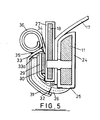
- Fig. 5 illustrates, to an enlarged scale, the manner in which, in practice, the sleeve 18 and frame 11 engage and support a valve leaflet 17.
- the frame 11 Prior to assembly, the frame 11 is enclosed in a covering 24 formed from a single piece of pericardial tissue. The tissue covering 24 is stitched at 25 to provide a double-layer tail 26 of tissue extending therefrom. It will be noted that the inner face of the frame 11 is seamless.
- the sleeve 18 is covered with a covering 27 of a cloth such as polyester which is stitched at 28 to provide a double-layered extension in the form of a cloth tail 29.
- valve leaflets 17 are positioned on the outwardly extending pins 15 and studs 16 of the tissue-covered inner fram 11, the leaflets being secured to each other by vertical stitched seams at their adjacent edges and tips. Securing washers (not shown) are then releasably affixed to the studs 16 to secure the leaflets 17 thereto.
- the cloth-covered outer sleeve 18 is then positioned, as shown in Fig.
- each valve leaflet 17 can be mounted accurately and securely in their desired position without the necessity for highly skilled suturing.
- the clamping of the tissue between the cloth-covered sleeve 18 and tissue covered frame 11 provides an even distribution of pressure on each valve leaflet 17 at its base regions and the studs 16 towards the top of the posts 13 will precisely locate the leaflets 17 thereon.
- the outer sleeve 18 protects the pericardial tissue against injury during insertion of the prosthesis and also against possible injury from long suture ends in the aortic position.
- an external double-layer cloth panel 31 is secured by stitching at 32 to the tissue tail 26.
- the cloth tail 29 of the cloth covering 27 of the outer sleeve 18 is folded upwardly over the outer face of locking ring 30 and the inner layer of tail 29 is secured by stitching at 33 along the upper edge of said ring.
- the tissue tail 26 and cloth panel 31 are subsequently folded upwardly over the secured tail 29 stitched at 33a.
- the outer layer of the cloth panel 31 is stitched at 34 to the inner layer of tail 29.
- the tissue tail 26 extends outwardly around the base of the valve to prevent host tissue ingrowth into the valve orifice.
- the outer layer of panel 31 and inner layer of tail 29 are continued upwardly and wound in a spiral and stitched at 35 to outer layer of panel 31 to form a sewing ring 36 whereby the prosthesis can be secured in its operative position. It will be apparent that the position of the sewing ring relative to the prosthesis can be varied as required in order to give a higher or lower valve profile as required.
- the posts 20 of the outer sleeve 18 can be linked by a connecting suture 23 (Fig. 1) to reduce the chance of snaring of sutures on the posts during insertion.
- the prosthesis described above is intended for a 27 mm. atrio-ventricular valve and it will be appreciated that the dimensions can be varied in order to suit requirements and for other valves which have to be employed at other locations.
Abstract
Description
- This invention relates to a heart valve prosthesis. Heart valve prostheses have previously been proposed in a number of forms. An early development in prosthetic heart valves involved the use of various types of mechanical valves such as flap valves or poppet valves. However, heart valve prostheses have utilised three flexible cusps. The cusps are in the form of flexible leaflets which are mounted for flexing about a generally cylindrical base. The leaflets can flex inwardly from the base into a closed position and can flex outwardly to lie in a general cylindrical formation in an open position. Two different types of tissue leaflet valves are commonly manufactured. In one type, complete porcine aortic valves are mounted inside a cylindrical support frame, commonly referred to as a stent. In another type, the leaflets are manufactured from bovine pericardium and also mounted on a frame. Normally the leaflets are mounted on their frame after having been treated with glutaraldehyde which crosslinks and stabilises the collagen in the leaflets and reduces their antigenicity.. Materials other than porcine aortic valves or bovine pericardium have been proposed for valve leaflets, for example polyurethane,but valves incorporating leaflets of such other materials are not commercially available for clinical implant at present.
- Various forms of frames have been proposed for the foregoing purpose. In, for example, British Patent No. 1,598,112, there is disclosed a heart valve prosthesis wherein the frame is formed by a frame system having a first frame defining three parallel legs on which the leaflets are mounted. A second frame cooperates with the first frame in order to clamp the leaflets therebetween so that the leaflets can be secured to and between the frames.
- In European Patent Publication No. 0051451A a heart valve prosthesis is shown in which a frame having a cylindrical base from which extends three integral upstanding legs is formed of a biologically compatible metal or plastic material. Three cooperating valve leaflets are mounted on the frame and are secured to the cylindrical base and to the upstanding legs by stitching. Stitches, referred to as coaptation stitches, secure each leaflet to the upper end of each leg in order to try to ensure that the leaflets deflect inwardly to enable the three leaflets to cooperate together to close the passage through the valve. The. frame is covered with a cloth in order to achieve well known biological advantages. The cloth also facilitates the fixing of an annular sewing ring to the outside of the prosthesis.
- The above-described previously proposed,arrangements have been found to be satisfactory in operation but because of their relatively complex construction and assembly, which involves sewing or the like in order to secure the leaflets to the frame, they have disadvantages in that they do not readily lend themselves to mass production techniques and are consequently relatively expensive to produce. The durability of these valves is not ideal. Mechanical failures and tears in the leaflets have been reported in the short term and biological effects such as calcification can cause valve malfunction in the longer term.
- An object of =the present invention is to provide a stent for a heart valve prosthesis in which some of the foregoing disadvantages are obviated or.mitigated.
- According to the present invention there is provided a heart valve prosthesis comprising an annular support frame for a plurality of flexible tissue valve elements, said support frame having a plurality of spaced posts defining openings therebetween to permit a portion of each valve element to flex from an open position to a closed position, and means for securing the valve elements to the support frame characterised in that the means for securing the valve elements to the support comprises an annular sleeve concentric with said support frame adapted to clamp a non-flexing portion of each valve element in operative position between the support frame and said sleeve.
- Preferably, the annular support is provided with a plurality of radially extending projections on which the valve elements and sleeve can be mounted to clamp the valve elements in their operative position.
- Preferably also, the profile of the clamping sleeve substantially corresponds to the profile of the annular support.
- An embodiment of the present invention will now be described by way of example, with reference to the accompanying drawings, in which:
- Fig. 1 is a perspective view of a heart valve prosthesis in accordance with the present invention incorporating an inner frame and an outer support sleeve securing a valve tissue provided by three valve leaflets therebetween. The prosthesis is provided with an outer cloth covering and an annular sewing ring;
- Fig. 2 is a perspective view of the inner frame;
- Fig. 3 is a perspective view of the outer support sleeve;
- Figs. 4a and 4b are diagrammatic representations illustrating vertical and horizontal sections of a valve leaflet; and
- Fig. 5 is a fragmentary vertical sectional view, to an enlarged scale, of a portion of the prosthesis illustrating the manner in which each valve leaflet is supported between the frame and the outer support sleeve.
- The prosthetic valve is intended for the atrio-ventricular or ventricular-aortic positions within a human heart and can have a range of sizes of from 25 to 33 mm. diameter for the mitral position and 19 to 27 mm. diameter for the aortic position. The prosthesis as illustrated in the accompanying drawings comprises an
inner frame 11 of any suitable biologically inert metal or synthetic plastics material, e.g., acetal. Theframe 11 comprises acylindrical base 12 from which extend upwardly towards the outflow end of the valve three spacedposts 13 integral with thebase 12 and which posts define scalloped spaces orsectors 14 therebetween. The outer peripheral edges of thebase 12 andposts 13 defining thescallops 14 are bevelled. Mounted in theframe 11 so as to project radially outwardly from thecylindrical base 12 are a plurality of,e.g., seven, tissue-locating pins orsimilar projections 15. It will be appreciated that thepins 15 do not project radially inwardly beyond the inner surface of theframe 11. From eachpost 13, a pair ofstuds 16 extend radially outwardly therefrom and washer elements (not shown) are engaged with said studs in order to secure a tissue therebetween. - A tissue formed of bovine pericardium or any other suitable natural or synthetic material is utilised to form three
valve leaflets 17. The threeleaflets 17 are secured to theinner frame 11 by affixing the leaflets 17on to the seven outwardly projectingpins 15 and twostuds 16. The perimeter of eachscallop 14 is defined by the intersection of a sphere of approximately 11 mm. radius with thecylindrical base 12 offrame 11. As indicated in Fig. 2, the width W of the tip of theposts 13 is approximately 2 mm., the scallop depth h is 14 mm. and the overall height H of the frame is 18 mm. The internal diameter of theframe 11 is approximately 23 mm. and its outside diameter approximately 25 mm. - An
outer support sleeve 18, which is of a suitable flexible biologically inactive material, e.g., acetal, is adapted to be positioned over the external surface of the adjoining leaflets and securedorerthe outer ends of thepins 15 in order to clamp the lower portion of theleaflets 17 between theinner frame 11 and theouter sleeve 18. Once again, it will be appreciated that thepins 15 do not extend beyond the outer surface of theouter sleeve 18. Theouter sleeve 18 has acylindrical base 19 provided with a series of holes 19a adapted to register with thepins 15 offrame 11. Thesleeve 18 also has spacedupstanding posts 20 similar to corresponding portions of theinner frame 11 so that the profiles of theframe 11 andouter sleeve 18 are generally in register with each other when they are located in their operative positions relative to one other. Theouter sleeve 18, however, is provided withposts 20 which are broader than those of theinner frame 11 in a circumferential direction and each has avertical slot 21 adjacent the overlapping region and into which slots the studs l6 and their associated securing washers project. Thecylindrical base 19 of theouter sleeve 18 is also provided withvertical slits 22 at the location of each post to enable thecylindrical base 19 of theouter sleeve 18 to be sufficiently distorted to allow it to be easily clipped in position around thebase 12 of theinner frame 11 to which theleaflets 17 have been affixed. - The base of the scallop of the outer frame l8 projects 1 mm. above the
base 12 ofinner frame 11 and the top of theposts 20 project about 2 mm. above their associatedposts 13 of theframe 11. As indicated in Fig. 3, the overall height H' ofouter sleeve 18 is 20 mm. and the scallop depth h' is 15 mm. The outside diameter of theouter sleeve 18 is 27 mm. and the internal diameter is about 26 mm. The width W of eachpost 20 at its upper tip is 7 mm. and thevertical slots 21 are approximately 2 mm. wide. - As shown in Fig. 4a in vertical section, one suitable form of each
leaflet 17 at its flexible portion above thebase 12 offrame 11 defines an initial angle of about 2Oo before curving through a radius R of about 11 mm. to extend towards its free edge in a substantially vertical direction. The height h" of the leaflet is approximately 15 mm. Fig. 4b shows the arcuate form of each leaflet when operatively located between its associatedposts 13. Eachleaflet 17 is preferably manufactured from bovine pericardium selected from specific areas of pericardial sac to give uniform thickness and extensibility. In manufacture of each leaflet it is positioned in a mould and placed in a glutaraldehyde bath to crosslink the tissue and produce the desired geometry for the leaflets. Holes for positioning eachleaflet 17 on thepins 15 andstuds 16 of theframe 11 are also made when each leaflet is on the mould. - It will be noted that the tips of the posts of the
outer sleeve 18 are rounded in order to reduce the risk of myocardial injury in the atrio-ventricular position. Fig. 5 illustrates, to an enlarged scale, the manner in which, in practice, thesleeve 18 andframe 11 engage and support avalve leaflet 17. Prior to assembly, theframe 11 is enclosed in a covering 24 formed from a single piece of pericardial tissue. The tissue covering 24 is stitched at 25 to provide a double-layer tail 26 of tissue extending therefrom. It will be noted that the inner face of theframe 11 is seamless. Thesleeve 18 is covered with a covering 27 of a cloth such as polyester which is stitched at 28 to provide a double-layered extension in the form of acloth tail 29. - On assembly of the prosthesis of the invention,
valve leaflets 17 are positioned on the outwardly extendingpins 15 andstuds 16 of the tissue-coveredinner fram 11, the leaflets being secured to each other by vertical stitched seams at their adjacent edges and tips. Securing washers (not shown) are then releasably affixed to thestuds 16 to secure theleaflets 17 thereto. The cloth-coveredouter sleeve 18 is then positioned, as shown in Fig. 5, on the outside of the mountedleaflets 17 on thepins 15 andbase 19 of theouter sleeve 18 is secured on to theinner frame 11 by means of a surrounding acetal locking or clampingring 30, the vertical edges ofleaflets 17, thestuds 16 and associated securing washers being accommodated within the slots 21 (Fig. 3) of theouter sleeve 18. In this way, eachvalve leaflet 17 can be mounted accurately and securely in their desired position without the necessity for highly skilled suturing. The clamping of the tissue between the cloth-coveredsleeve 18 and tissue coveredframe 11 provides an even distribution of pressure on eachvalve leaflet 17 at its base regions and thestuds 16 towards the top of theposts 13 will precisely locate theleaflets 17 thereon. In addition, theouter sleeve 18 protects the pericardial tissue against injury during insertion of the prosthesis and also against possible injury from long suture ends in the aortic position. - As shown in Fig. 5, an external double-
layer cloth panel 31 is secured by stitching at 32 to thetissue tail 26. - The
cloth tail 29 of the cloth covering 27 of theouter sleeve 18 is folded upwardly over the outer face of lockingring 30 and the inner layer oftail 29 is secured by stitching at 33 along the upper edge of said ring. Thetissue tail 26 andcloth panel 31 are subsequently folded upwardly over thesecured tail 29 stitched at 33a. The outer layer of thecloth panel 31 is stitched at 34 to the inner layer oftail 29. Thetissue tail 26 extends outwardly around the base of the valve to prevent host tissue ingrowth into the valve orifice. The outer layer ofpanel 31 and inner layer oftail 29 are continued upwardly and wound in a spiral and stitched at 35 to outer layer ofpanel 31 to form asewing ring 36 whereby the prosthesis can be secured in its operative position. It will be apparent that the position of the sewing ring relative to the prosthesis can be varied as required in order to give a higher or lower valve profile as required. - If desired, in the atrio-ventricular position the
posts 20 of theouter sleeve 18 can be linked by a connecting suture 23 (Fig. 1) to reduce the chance of snaring of sutures on the posts during insertion. - The prosthesis described above is intended for a 27 mm. atrio-ventricular valve and it will be appreciated that the dimensions can be varied in order to suit requirements and for other valves which have to be employed at other locations.
- Although it has commonly been found desirable to provide three valve leaflets in a heart valve prosthesis of the type to which the present invention relates, it will be appreciated that it may be possible to use a number of leaflets other than three e.g., two.
- It will be appreciated by those skilled in the art that the beneficial functions of a valve produced in accordance with the present invention depend upon care being taken with respect to a number of parameters, e.g., selection and preliminary treatment of the valve leaflets in accordance with accepted practice.
Claims (15)
Priority Applications (1)
| Application Number | Priority Date | Filing Date | Title |
|---|---|---|---|
| AT85306549T ATE44451T1 (en) | 1984-09-28 | 1985-09-16 | HEART VALVE PROSTHESIS. |
Applications Claiming Priority (2)
| Application Number | Priority Date | Filing Date | Title |
|---|---|---|---|
| GB8424582 | 1984-09-28 | ||
| GB848424582A GB8424582D0 (en) | 1984-09-28 | 1984-09-28 | Heart valve prosthesis |
Publications (2)
| Publication Number | Publication Date |
|---|---|
| EP0179562A1 true EP0179562A1 (en) | 1986-04-30 |
| EP0179562B1 EP0179562B1 (en) | 1989-07-12 |
Family
ID=10567420
Family Applications (1)
| Application Number | Title | Priority Date | Filing Date |
|---|---|---|---|
| EP85306549A Expired EP0179562B1 (en) | 1984-09-28 | 1985-09-16 | A heart valve prosthesis |
Country Status (8)
| Country | Link |
|---|---|
| US (1) | US4687483A (en) |
| EP (1) | EP0179562B1 (en) |
| JP (1) | JPS61179147A (en) |
| AT (1) | ATE44451T1 (en) |
| CA (1) | CA1243453A (en) |
| DE (1) | DE3571386D1 (en) |
| ES (1) | ES296391Y (en) |
| GB (1) | GB8424582D0 (en) |
Cited By (40)
| Publication number | Priority date | Publication date | Assignee | Title |
|---|---|---|---|---|
| WO1992012690A1 (en) * | 1991-01-24 | 1992-08-06 | Autogenics | Heart valve with tissue alignment and clamping |
| DE4316971A1 (en) * | 1993-05-21 | 1994-11-24 | Georg Dr Berg | Valve device for insertion in a hollow organ, a vessel or the like |
| WO1995016412A1 (en) * | 1993-12-17 | 1995-06-22 | Autogenics | Stents for autologous tissue heart valve |
| US5910170A (en) * | 1997-12-17 | 1999-06-08 | St. Jude Medical, Inc. | Prosthetic heart valve stent utilizing mounting clips |
| WO2000018333A1 (en) * | 1998-09-28 | 2000-04-06 | Autogenics | Heart valve having tissue retention with anchors and an outer sheath |
| US6629534B1 (en) | 1999-04-09 | 2003-10-07 | Evalve, Inc. | Methods and apparatus for cardiac valve repair |
| US6752813B2 (en) | 1999-04-09 | 2004-06-22 | Evalve, Inc. | Methods and devices for capturing and fixing leaflets in valve repair |
| US7048754B2 (en) | 2002-03-01 | 2006-05-23 | Evalve, Inc. | Suture fasteners and methods of use |
| WO2008133852A1 (en) * | 2007-04-26 | 2008-11-06 | St. Jude Medical, Inc. | Techniques for attaching flexible leaflets of prosthetic heart valves to supporting structures |
| US7509959B2 (en) | 1997-06-27 | 2009-03-31 | The Trustees Of Columbia University In The City Of New York | Method and apparatus for circulatory valve repair |
| US7981123B2 (en) * | 1997-09-12 | 2011-07-19 | Evalve, Inc. | Surgical device for connecting soft tissue |
| US8052592B2 (en) | 2005-09-27 | 2011-11-08 | Evalve, Inc. | Methods and devices for tissue grasping and assessment |
| US8057493B2 (en) | 1999-04-09 | 2011-11-15 | Evalve, Inc. | Fixation devices, systems and methods for engaging tissue |
| US8123703B2 (en) | 1999-04-09 | 2012-02-28 | Evalve, Inc. | Steerable access sheath and methods of use |
| US8343174B2 (en) | 1999-04-09 | 2013-01-01 | Evalve, Inc. | Locking mechanisms for fixation devices and methods of engaging tissue |
| RU2487781C2 (en) * | 2007-12-14 | 2013-07-20 | Кеннаметал, Инк. | Article with nano-layer coating |
| US8518108B2 (en) | 1997-03-27 | 2013-08-27 | Edwards Lifesciences Corporation | Contoured heart valve suture rings |
| US8641757B2 (en) | 2010-09-10 | 2014-02-04 | Edwards Lifesciences Corporation | Systems for rapidly deploying surgical heart valves |
| US8696742B2 (en) | 2009-06-26 | 2014-04-15 | Edwards Lifesciences Corporation | Unitary quick-connect prosthetic heart valve deployment methods |
| US8845720B2 (en) | 2010-09-27 | 2014-09-30 | Edwards Lifesciences Corporation | Prosthetic heart valve frame with flexible commissures |
| US8986374B2 (en) | 2010-05-10 | 2015-03-24 | Edwards Lifesciences Corporation | Prosthetic heart valve |
| US9005278B2 (en) | 2008-12-19 | 2015-04-14 | Edwards Lifesciences Corporation | Quick-connect prosthetic heart valve |
| US9078747B2 (en) | 2011-12-21 | 2015-07-14 | Edwards Lifesciences Corporation | Anchoring device for replacing or repairing a heart valve |
| US9125741B2 (en) | 2010-09-10 | 2015-09-08 | Edwards Lifesciences Corporation | Systems and methods for ensuring safe and rapid deployment of prosthetic heart valves |
| US9370418B2 (en) | 2010-09-10 | 2016-06-21 | Edwards Lifesciences Corporation | Rapidly deployable surgical heart valves |
| US9603553B2 (en) | 2009-10-27 | 2017-03-28 | Edwards Lifesciences Corporation | Methods of measuring heart valve annuluses for valve replacement |
| US10363138B2 (en) | 2016-11-09 | 2019-07-30 | Evalve, Inc. | Devices for adjusting the curvature of cardiac valve structures |
| US10376673B2 (en) | 2015-06-19 | 2019-08-13 | Evalve, Inc. | Catheter guiding system and methods |
| US10390943B2 (en) | 2014-03-17 | 2019-08-27 | Evalve, Inc. | Double orifice device for transcatheter mitral valve replacement |
| US10398553B2 (en) | 2016-11-11 | 2019-09-03 | Evalve, Inc. | Opposing disk device for grasping cardiac valve tissue |
| US10413408B2 (en) | 2015-08-06 | 2019-09-17 | Evalve, Inc. | Delivery catheter systems, methods, and devices |
| US10426616B2 (en) | 2016-11-17 | 2019-10-01 | Evalve, Inc. | Cardiac implant delivery system |
| US10463480B2 (en) | 2010-05-12 | 2019-11-05 | Edwards Lifesciences Corporation | Leaflet for low gradient prosthetic heart valve |
| US10524912B2 (en) | 2015-04-02 | 2020-01-07 | Abbott Cardiovascular Systems, Inc. | Tissue fixation devices and methods |
| US10667815B2 (en) | 2015-07-21 | 2020-06-02 | Evalve, Inc. | Tissue grasping devices and related methods |
| US10667804B2 (en) | 2014-03-17 | 2020-06-02 | Evalve, Inc. | Mitral valve fixation device removal devices and methods |
| US10736632B2 (en) | 2016-07-06 | 2020-08-11 | Evalve, Inc. | Methods and devices for valve clip excision |
| US10779837B2 (en) | 2016-12-08 | 2020-09-22 | Evalve, Inc. | Adjustable arm device for grasping tissues |
| US10842623B2 (en) | 2009-03-31 | 2020-11-24 | Edwards Lifesciences Corporation | Methods of implanting prosthetic heart valve using position markers |
| US11071564B2 (en) | 2016-10-05 | 2021-07-27 | Evalve, Inc. | Cardiac valve cutting device |
Families Citing this family (108)
| Publication number | Priority date | Publication date | Assignee | Title |
|---|---|---|---|---|
| DK124690D0 (en) * | 1990-05-18 | 1990-05-18 | Henning Rud Andersen | FAT PROTECTION FOR IMPLEMENTATION IN THE BODY FOR REPLACEMENT OF NATURAL FLEET AND CATS FOR USE IN IMPLEMENTING A SUCH FAT PROTECTION |
| US5489298A (en) * | 1991-01-24 | 1996-02-06 | Autogenics | Rapid assembly concentric mating stent, tissue heart valve with enhanced clamping and tissue exposure |
| ES2028611A6 (en) * | 1991-02-07 | 1992-07-01 | Garcia Gonzalez Moro Jose Beni | Artificial heart valve. |
| DE4222610A1 (en) * | 1992-07-10 | 1994-01-13 | Jansen Josef Dr Ing | Support housing for flap and closing elements |
| WO1994004099A1 (en) * | 1992-08-13 | 1994-03-03 | Autogenics | Tissue heart valve with concentric mating stents |
| JPH071836U (en) * | 1993-06-11 | 1995-01-13 | ナショナル住宅産業株式会社 | Movable leg device |
| US5425741A (en) * | 1993-12-17 | 1995-06-20 | Autogenics | Tissue cutting die |
| EP0853465A4 (en) | 1995-09-01 | 1999-10-27 | Univ Emory | Endovascular support device and method of use |
| US6402780B2 (en) | 1996-02-23 | 2002-06-11 | Cardiovascular Technologies, L.L.C. | Means and method of replacing a heart valve in a minimally invasive manner |
| EP0850607A1 (en) | 1996-12-31 | 1998-07-01 | Cordis Corporation | Valve prosthesis for implantation in body channels |
| US5961549A (en) * | 1997-04-03 | 1999-10-05 | Baxter International Inc. | Multi-leaflet bioprosthetic heart valve |
| US6530952B2 (en) | 1997-12-29 | 2003-03-11 | The Cleveland Clinic Foundation | Bioprosthetic cardiovascular valve system |
| US6106550A (en) * | 1998-07-10 | 2000-08-22 | Sulzer Carbomedics Inc. | Implantable attaching ring |
| JP2002527191A (en) * | 1998-10-20 | 2002-08-27 | ティーイーアイ バイオサイエンシス インク | Cardiovascular component for transplantation and method of manufacturing the same |
| US10327743B2 (en) | 1999-04-09 | 2019-06-25 | Evalve, Inc. | Device and methods for endoscopic annuloplasty |
| US8216256B2 (en) | 1999-04-09 | 2012-07-10 | Evalve, Inc. | Detachment mechanism for implantable fixation devices |
| US7811296B2 (en) | 1999-04-09 | 2010-10-12 | Evalve, Inc. | Fixation devices for variation in engagement of tissue |
| DK1255510T5 (en) * | 2000-01-31 | 2009-12-21 | Cook Biotech Inc | Stent Valve Klapper |
| DE10010073B4 (en) | 2000-02-28 | 2005-12-22 | Fraunhofer-Gesellschaft zur Förderung der angewandten Forschung e.V. | Anchoring for implantable heart valve prostheses |
| US6378221B1 (en) | 2000-02-29 | 2002-04-30 | Edwards Lifesciences Corporation | Systems and methods for mapping and marking the thickness of bioprosthetic sheet |
| US8366769B2 (en) | 2000-06-01 | 2013-02-05 | Edwards Lifesciences Corporation | Low-profile, pivotable heart valve sewing ring |
| US6409758B2 (en) | 2000-07-27 | 2002-06-25 | Edwards Lifesciences Corporation | Heart valve holder for constricting the valve commissures and methods of use |
| DE10107799C2 (en) * | 2001-02-16 | 2003-06-26 | Tricumed Medizintechnik Gmbh | Heart valve prosthesis with suture fastening pin |
| US6936067B2 (en) * | 2001-05-17 | 2005-08-30 | St. Jude Medical Inc. | Prosthetic heart valve with slit stent |
| US6719785B2 (en) | 2001-05-17 | 2004-04-13 | St. Jude Medical, Inc. | Aortic heart valve prosthesis implantation tool |
| US6893460B2 (en) | 2001-10-11 | 2005-05-17 | Percutaneous Valve Technologies Inc. | Implantable prosthetic valve |
| GB0125925D0 (en) * | 2001-10-29 | 2001-12-19 | Univ Glasgow | Mitral valve prosthesis |
| US7201771B2 (en) | 2001-12-27 | 2007-04-10 | Arbor Surgical Technologies, Inc. | Bioprosthetic heart valve |
| US7959674B2 (en) | 2002-07-16 | 2011-06-14 | Medtronic, Inc. | Suture locking assembly and method of use |
| US8551162B2 (en) | 2002-12-20 | 2013-10-08 | Medtronic, Inc. | Biologically implantable prosthesis |
| US10667823B2 (en) | 2003-05-19 | 2020-06-02 | Evalve, Inc. | Fixation devices, systems and methods for engaging tissue |
| US8021421B2 (en) | 2003-08-22 | 2011-09-20 | Medtronic, Inc. | Prosthesis heart valve fixturing device |
| US7556647B2 (en) | 2003-10-08 | 2009-07-07 | Arbor Surgical Technologies, Inc. | Attachment device and methods of using the same |
| US7871435B2 (en) | 2004-01-23 | 2011-01-18 | Edwards Lifesciences Corporation | Anatomically approximate prosthetic mitral heart valve |
| US7635329B2 (en) | 2004-09-27 | 2009-12-22 | Evalve, Inc. | Methods and devices for tissue grasping and assessment |
| US7758640B2 (en) * | 2004-12-16 | 2010-07-20 | Valvexchange Inc. | Cardiovascular valve assembly |
| DE102005003632A1 (en) | 2005-01-20 | 2006-08-17 | Fraunhofer-Gesellschaft zur Förderung der angewandten Forschung e.V. | Catheter for the transvascular implantation of heart valve prostheses |
| US20060229708A1 (en) | 2005-02-07 | 2006-10-12 | Powell Ferolyn T | Methods, systems and devices for cardiac valve repair |
| US8574257B2 (en) | 2005-02-10 | 2013-11-05 | Edwards Lifesciences Corporation | System, device, and method for providing access in a cardiovascular environment |
| US7513909B2 (en) | 2005-04-08 | 2009-04-07 | Arbor Surgical Technologies, Inc. | Two-piece prosthetic valves with snap-in connection and methods for use |
| CN101180010B (en) | 2005-05-24 | 2010-12-01 | 爱德华兹生命科学公司 | Rapid deployment prosthetic heart valve |
| WO2006127985A2 (en) * | 2005-05-26 | 2006-11-30 | Texas Heart Institute | Surgical system and method for attaching a prosthetic vessel to a hollow structure |
| US8211169B2 (en) | 2005-05-27 | 2012-07-03 | Medtronic, Inc. | Gasket with collar for prosthetic heart valves and methods for using them |
| US7238200B2 (en) * | 2005-06-03 | 2007-07-03 | Arbor Surgical Technologies, Inc. | Apparatus and methods for making leaflets and valve prostheses including such leaflets |
| US7682391B2 (en) | 2005-07-13 | 2010-03-23 | Edwards Lifesciences Corporation | Methods of implanting a prosthetic mitral heart valve having a contoured sewing ring |
| US7967857B2 (en) | 2006-01-27 | 2011-06-28 | Medtronic, Inc. | Gasket with spring collar for prosthetic heart valves and methods for making and using them |
| US8075615B2 (en) | 2006-03-28 | 2011-12-13 | Medtronic, Inc. | Prosthetic cardiac valve formed from pericardium material and methods of making same |
| JP2009535128A (en) | 2006-04-29 | 2009-10-01 | アーバー・サージカル・テクノロジーズ・インコーポレイテッド | Multi-part prosthetic heart valve assembly and apparatus and method for delivering the same |
| US8021161B2 (en) | 2006-05-01 | 2011-09-20 | Edwards Lifesciences Corporation | Simulated heart valve root for training and testing |
| US20080004696A1 (en) * | 2006-06-29 | 2008-01-03 | Valvexchange Inc. | Cardiovascular valve assembly with resizable docking station |
| US8092523B2 (en) * | 2007-03-12 | 2012-01-10 | St. Jude Medical, Inc. | Prosthetic heart valves with flexible leaflets |
| US7896915B2 (en) | 2007-04-13 | 2011-03-01 | Jenavalve Technology, Inc. | Medical device for treating a heart valve insufficiency |
| US7815677B2 (en) * | 2007-07-09 | 2010-10-19 | Leman Cardiovascular Sa | Reinforcement device for a biological valve and reinforced biological valve |
| WO2009045331A1 (en) * | 2007-09-28 | 2009-04-09 | St. Jude Medical, Inc. | Two-stage collapsible/expandable prosthetic heart valves and anchoring systems |
| US9044318B2 (en) | 2008-02-26 | 2015-06-02 | Jenavalve Technology Gmbh | Stent for the positioning and anchoring of a valvular prosthesis |
| ES2903231T3 (en) | 2008-02-26 | 2022-03-31 | Jenavalve Tech Inc | Stent for positioning and anchoring a valve prosthesis at an implantation site in a patient's heart |
| WO2009111241A2 (en) | 2008-02-29 | 2009-09-11 | The Florida International University Board Of Trustees | Catheter deliverable artificial multi-leaflet heart valve prosthesis and intravascular delivery system for a catheter deliverable heart valve prosthesis |
| WO2010030859A1 (en) * | 2008-09-12 | 2010-03-18 | Valvexchange Inc. | Valve assembly with exchangeable valve member and a tool set for exchanging the valve member |
| EP2370138B1 (en) | 2008-11-25 | 2020-12-30 | Edwards Lifesciences Corporation | Apparatus for in situ expansion of prosthetic device |
| EP2477555B1 (en) | 2009-09-15 | 2013-12-25 | Evalve, Inc. | Device for cardiac valve repair |
| JP2013526388A (en) | 2010-05-25 | 2013-06-24 | イエナバルブ テクノロジー インク | Artificial heart valve, and transcatheter delivery prosthesis comprising an artificial heart valve and a stent |
| US8845717B2 (en) | 2011-01-28 | 2014-09-30 | Middle Park Medical, Inc. | Coaptation enhancement implant, system, and method |
| US8888843B2 (en) | 2011-01-28 | 2014-11-18 | Middle Peak Medical, Inc. | Device, system, and method for transcatheter treatment of valve regurgitation |
| US8945209B2 (en) | 2011-05-20 | 2015-02-03 | Edwards Lifesciences Corporation | Encapsulated heart valve |
| US9358107B2 (en) | 2011-06-30 | 2016-06-07 | Edwards Lifesciences Corporation | Systems, dies, and methods for processing pericardial tissue |
| EP2734153A2 (en) | 2011-07-20 | 2014-05-28 | Boston Scientific Scimed, Inc. | Heart valve replacement |
| US8945177B2 (en) | 2011-09-13 | 2015-02-03 | Abbott Cardiovascular Systems Inc. | Gripper pusher mechanism for tissue apposition systems |
| WO2014145811A1 (en) | 2013-03-15 | 2014-09-18 | Edwards Lifesciences Corporation | Valved aortic conduits |
| US11007058B2 (en) | 2013-03-15 | 2021-05-18 | Edwards Lifesciences Corporation | Valved aortic conduits |
| US9468527B2 (en) * | 2013-06-12 | 2016-10-18 | Edwards Lifesciences Corporation | Cardiac implant with integrated suture fasteners |
| US9919137B2 (en) | 2013-08-28 | 2018-03-20 | Edwards Lifesciences Corporation | Integrated balloon catheter inflation system |
| JP6563394B2 (en) | 2013-08-30 | 2019-08-21 | イェーナヴァルヴ テクノロジー インコーポレイテッド | Radially foldable frame for an artificial valve and method for manufacturing the frame |
| CN105263445B (en) | 2013-09-20 | 2018-09-18 | 爱德华兹生命科学公司 | Heart valve with increased effective orifice area |
| US10166098B2 (en) | 2013-10-25 | 2019-01-01 | Middle Peak Medical, Inc. | Systems and methods for transcatheter treatment of valve regurgitation |
| US20150122687A1 (en) | 2013-11-06 | 2015-05-07 | Edwards Lifesciences Corporation | Bioprosthetic heart valves having adaptive seals to minimize paravalvular leakage |
| US9549816B2 (en) | 2014-04-03 | 2017-01-24 | Edwards Lifesciences Corporation | Method for manufacturing high durability heart valve |
| US9585752B2 (en) | 2014-04-30 | 2017-03-07 | Edwards Lifesciences Corporation | Holder and deployment system for surgical heart valves |
| ES2908178T3 (en) | 2014-06-18 | 2022-04-28 | Polares Medical Inc | Mitral valve implants for the treatment of valvular regurgitation |
| CA2914094C (en) | 2014-06-20 | 2021-01-05 | Edwards Lifesciences Corporation | Surgical heart valves identifiable post-implant |
| USD867594S1 (en) | 2015-06-19 | 2019-11-19 | Edwards Lifesciences Corporation | Prosthetic heart valve |
| EP3160396B1 (en) | 2014-06-24 | 2022-03-23 | Polares Medical Inc. | Systems for anchoring an implant |
| US10188392B2 (en) | 2014-12-19 | 2019-01-29 | Abbott Cardiovascular Systems, Inc. | Grasping for tissue repair |
| US10709555B2 (en) | 2015-05-01 | 2020-07-14 | Jenavalve Technology, Inc. | Device and method with reduced pacemaker rate in heart valve replacement |
| US10238494B2 (en) | 2015-06-29 | 2019-03-26 | Evalve, Inc. | Self-aligning radiopaque ring |
| CR20170597A (en) | 2015-07-02 | 2018-04-20 | Edwards Lifesciences Corp | INTEGRATED HYBRID HEART VALVES |
| WO2017004369A1 (en) | 2015-07-02 | 2017-01-05 | Edwards Lifesciences Corporation | Hybrid heart valves adapted for post-implant expansion |
| CA2995855C (en) | 2015-09-02 | 2024-01-30 | Edwards Lifesciences Corporation | Spacer for securing a transcatheter valve to a bioprosthetic cardiac structure |
| US10080653B2 (en) | 2015-09-10 | 2018-09-25 | Edwards Lifesciences Corporation | Limited expansion heart valve |
| US10238495B2 (en) | 2015-10-09 | 2019-03-26 | Evalve, Inc. | Delivery catheter handle and methods of use |
| US9592121B1 (en) | 2015-11-06 | 2017-03-14 | Middle Peak Medical, Inc. | Device, system, and method for transcatheter treatment of valvular regurgitation |
| US10667904B2 (en) | 2016-03-08 | 2020-06-02 | Edwards Lifesciences Corporation | Valve implant with integrated sensor and transmitter |
| EP3454795B1 (en) | 2016-05-13 | 2023-01-11 | JenaValve Technology, Inc. | Heart valve prosthesis delivery system for delivery of heart valve prosthesis with introducer sheath and loading system |
| US10456245B2 (en) | 2016-05-16 | 2019-10-29 | Edwards Lifesciences Corporation | System and method for applying material to a stent |
| US10314586B2 (en) | 2016-12-13 | 2019-06-11 | Evalve, Inc. | Rotatable device and method for fixing tricuspid valve tissue |
| USD846122S1 (en) | 2016-12-16 | 2019-04-16 | Edwards Lifesciences Corporation | Heart valve sizer |
| JP7094965B2 (en) | 2017-01-27 | 2022-07-04 | イエナバルブ テクノロジー インク | Heart valve imitation |
| CN110913801B (en) | 2017-03-13 | 2022-04-15 | 宝来瑞斯医疗有限公司 | Coaptation assistance element for treating an adverse coaptation of a heart valve of a heart and system for delivering the same |
| US10653524B2 (en) | 2017-03-13 | 2020-05-19 | Polares Medical Inc. | Device, system, and method for transcatheter treatment of valvular regurgitation |
| US10478303B2 (en) | 2017-03-13 | 2019-11-19 | Polares Medical Inc. | Device, system, and method for transcatheter treatment of valvular regurgitation |
| US10463485B2 (en) | 2017-04-06 | 2019-11-05 | Edwards Lifesciences Corporation | Prosthetic valve holders with automatic deploying mechanisms |
| EP3614969B1 (en) | 2017-04-28 | 2023-05-03 | Edwards Lifesciences Corporation | Prosthetic heart valve with collapsible holder |
| US11065119B2 (en) | 2017-05-12 | 2021-07-20 | Evalve, Inc. | Long arm valve repair clip |
| EP3641700A4 (en) | 2017-06-21 | 2020-08-05 | Edwards Lifesciences Corporation | Dual-wireform limited expansion heart valves |
| US11337805B2 (en) | 2018-01-23 | 2022-05-24 | Edwards Lifesciences Corporation | Prosthetic valve holders, systems, and methods |
| USD908874S1 (en) | 2018-07-11 | 2021-01-26 | Edwards Lifesciences Corporation | Collapsible heart valve sizer |
| CN114641263A (en) | 2019-12-16 | 2022-06-17 | 爱德华兹生命科学公司 | Valve holder assembly with suture looping protection |
| US11464634B2 (en) | 2020-12-16 | 2022-10-11 | Polares Medical Inc. | Device, system, and method for transcatheter treatment of valvular regurgitation with secondary anchors |
| US11759321B2 (en) | 2021-06-25 | 2023-09-19 | Polares Medical Inc. | Device, system, and method for transcatheter treatment of valvular regurgitation |
Citations (5)
| Publication number | Priority date | Publication date | Assignee | Title |
|---|---|---|---|---|
| US3574865A (en) * | 1968-08-08 | 1971-04-13 | Michigan Instr Inc | Prosthetic sutureless heart valve |
| GB1598112A (en) * | 1977-02-23 | 1981-09-16 | Davis R B Skelton J Clark R E | Heart valve prosthesis |
| EP0051451A2 (en) * | 1980-11-03 | 1982-05-12 | Shiley Incorporated | Low profile prosthetic xenograft heart valve |
| EP0116236A1 (en) * | 1983-01-11 | 1984-08-22 | The University Of Sheffield | Heart valve replacements |
| US4470157A (en) * | 1981-04-27 | 1984-09-11 | Love Jack W | Tricuspid prosthetic tissue heart valve |
Family Cites Families (1)
| Publication number | Priority date | Publication date | Assignee | Title |
|---|---|---|---|---|
| US2922437A (en) * | 1955-03-16 | 1960-01-26 | Gen Motors Corp | Fluid flow control means |
-
1984
- 1984-09-28 GB GB848424582A patent/GB8424582D0/en active Pending
-
1985
- 1985-09-11 US US06/774,823 patent/US4687483A/en not_active Expired - Fee Related
- 1985-09-16 EP EP85306549A patent/EP0179562B1/en not_active Expired
- 1985-09-16 DE DE8585306549T patent/DE3571386D1/en not_active Expired
- 1985-09-16 AT AT85306549T patent/ATE44451T1/en not_active IP Right Cessation
- 1985-09-27 ES ES1985296391U patent/ES296391Y/en not_active Expired
- 1985-09-27 CA CA000491727A patent/CA1243453A/en not_active Expired
- 1985-09-28 JP JP60216052A patent/JPS61179147A/en active Granted
Patent Citations (5)
| Publication number | Priority date | Publication date | Assignee | Title |
|---|---|---|---|---|
| US3574865A (en) * | 1968-08-08 | 1971-04-13 | Michigan Instr Inc | Prosthetic sutureless heart valve |
| GB1598112A (en) * | 1977-02-23 | 1981-09-16 | Davis R B Skelton J Clark R E | Heart valve prosthesis |
| EP0051451A2 (en) * | 1980-11-03 | 1982-05-12 | Shiley Incorporated | Low profile prosthetic xenograft heart valve |
| US4470157A (en) * | 1981-04-27 | 1984-09-11 | Love Jack W | Tricuspid prosthetic tissue heart valve |
| EP0116236A1 (en) * | 1983-01-11 | 1984-08-22 | The University Of Sheffield | Heart valve replacements |
Cited By (60)
| Publication number | Priority date | Publication date | Assignee | Title |
|---|---|---|---|---|
| WO1992012690A1 (en) * | 1991-01-24 | 1992-08-06 | Autogenics | Heart valve with tissue alignment and clamping |
| DE4316971A1 (en) * | 1993-05-21 | 1994-11-24 | Georg Dr Berg | Valve device for insertion in a hollow organ, a vessel or the like |
| WO1995016412A1 (en) * | 1993-12-17 | 1995-06-22 | Autogenics | Stents for autologous tissue heart valve |
| US8518108B2 (en) | 1997-03-27 | 2013-08-27 | Edwards Lifesciences Corporation | Contoured heart valve suture rings |
| US8721665B2 (en) | 1997-06-27 | 2014-05-13 | The Trustees Of Columbia University In The City Of New York | Method and apparatus for circulatory valve repair |
| US7509959B2 (en) | 1997-06-27 | 2009-03-31 | The Trustees Of Columbia University In The City Of New York | Method and apparatus for circulatory valve repair |
| US8133239B2 (en) | 1997-06-27 | 2012-03-13 | The Trustees Of Columbia University In The City Of New York | Method and apparatus for circulatory valve repair |
| US7981123B2 (en) * | 1997-09-12 | 2011-07-19 | Evalve, Inc. | Surgical device for connecting soft tissue |
| US5910170A (en) * | 1997-12-17 | 1999-06-08 | St. Jude Medical, Inc. | Prosthetic heart valve stent utilizing mounting clips |
| WO2000018333A1 (en) * | 1998-09-28 | 2000-04-06 | Autogenics | Heart valve having tissue retention with anchors and an outer sheath |
| US6629534B1 (en) | 1999-04-09 | 2003-10-07 | Evalve, Inc. | Methods and apparatus for cardiac valve repair |
| US6752813B2 (en) | 1999-04-09 | 2004-06-22 | Evalve, Inc. | Methods and devices for capturing and fixing leaflets in valve repair |
| US8734505B2 (en) | 1999-04-09 | 2014-05-27 | Evalve, Inc. | Methods and apparatus for cardiac valve repair |
| US8057493B2 (en) | 1999-04-09 | 2011-11-15 | Evalve, Inc. | Fixation devices, systems and methods for engaging tissue |
| US8123703B2 (en) | 1999-04-09 | 2012-02-28 | Evalve, Inc. | Steerable access sheath and methods of use |
| US8343174B2 (en) | 1999-04-09 | 2013-01-01 | Evalve, Inc. | Locking mechanisms for fixation devices and methods of engaging tissue |
| US7048754B2 (en) | 2002-03-01 | 2006-05-23 | Evalve, Inc. | Suture fasteners and methods of use |
| US8052592B2 (en) | 2005-09-27 | 2011-11-08 | Evalve, Inc. | Methods and devices for tissue grasping and assessment |
| US8409274B2 (en) | 2007-04-26 | 2013-04-02 | St. Jude Medical, Inc. | Techniques for attaching flexible leaflets of prosthetic heart valves to supporting structures |
| WO2008133852A1 (en) * | 2007-04-26 | 2008-11-06 | St. Jude Medical, Inc. | Techniques for attaching flexible leaflets of prosthetic heart valves to supporting structures |
| RU2487781C2 (en) * | 2007-12-14 | 2013-07-20 | Кеннаметал, Инк. | Article with nano-layer coating |
| US9005278B2 (en) | 2008-12-19 | 2015-04-14 | Edwards Lifesciences Corporation | Quick-connect prosthetic heart valve |
| US10842623B2 (en) | 2009-03-31 | 2020-11-24 | Edwards Lifesciences Corporation | Methods of implanting prosthetic heart valve using position markers |
| US8696742B2 (en) | 2009-06-26 | 2014-04-15 | Edwards Lifesciences Corporation | Unitary quick-connect prosthetic heart valve deployment methods |
| US9005277B2 (en) | 2009-06-26 | 2015-04-14 | Edwards Lifesciences Corporation | Unitary quick-connect prosthetic heart valve deployment system |
| US9603553B2 (en) | 2009-10-27 | 2017-03-28 | Edwards Lifesciences Corporation | Methods of measuring heart valve annuluses for valve replacement |
| US10231646B2 (en) | 2009-10-27 | 2019-03-19 | Edwards Lifesciences Corporation | Device for measuring an aortic valve annulus in an expanded condition |
| US11412954B2 (en) | 2009-10-27 | 2022-08-16 | Edwards Lifesciences Corporation | Device for measuring an aortic valve annulus in an expanded condition |
| US8986374B2 (en) | 2010-05-10 | 2015-03-24 | Edwards Lifesciences Corporation | Prosthetic heart valve |
| US10463480B2 (en) | 2010-05-12 | 2019-11-05 | Edwards Lifesciences Corporation | Leaflet for low gradient prosthetic heart valve |
| US9370418B2 (en) | 2010-09-10 | 2016-06-21 | Edwards Lifesciences Corporation | Rapidly deployable surgical heart valves |
| US10548728B2 (en) | 2010-09-10 | 2020-02-04 | Edwards Lifesciences Corporation | Safety systems for expansion of prosthetic heart valves |
| US10039641B2 (en) | 2010-09-10 | 2018-08-07 | Edwards Lifesciences Corporation | Methods of rapidly deployable surgical heart valves |
| US9125741B2 (en) | 2010-09-10 | 2015-09-08 | Edwards Lifesciences Corporation | Systems and methods for ensuring safe and rapid deployment of prosthetic heart valves |
| US11775613B2 (en) | 2010-09-10 | 2023-10-03 | Edwards Lifesciences Corporation | Methods of safely expanding prosthetic heart valves |
| US10722358B2 (en) | 2010-09-10 | 2020-07-28 | Edwards Lifesciences Corporation | Systems for rapidly deployable surgical heart valves |
| US11197757B2 (en) | 2010-09-10 | 2021-12-14 | Edwards Lifesciences Corporation | Methods of safely expanding prosthetic heart valves |
| US8641757B2 (en) | 2010-09-10 | 2014-02-04 | Edwards Lifesciences Corporation | Systems for rapidly deploying surgical heart valves |
| US9968450B2 (en) | 2010-09-10 | 2018-05-15 | Edwards Lifesciences Corporation | Methods for ensuring safe and rapid deployment of prosthetic heart valves |
| US11471279B2 (en) | 2010-09-10 | 2022-10-18 | Edwards Lifesciences Corporation | Systems for rapidly deployable surgical heart valves |
| US8845720B2 (en) | 2010-09-27 | 2014-09-30 | Edwards Lifesciences Corporation | Prosthetic heart valve frame with flexible commissures |
| US9078747B2 (en) | 2011-12-21 | 2015-07-14 | Edwards Lifesciences Corporation | Anchoring device for replacing or repairing a heart valve |
| US10390943B2 (en) | 2014-03-17 | 2019-08-27 | Evalve, Inc. | Double orifice device for transcatheter mitral valve replacement |
| US10667804B2 (en) | 2014-03-17 | 2020-06-02 | Evalve, Inc. | Mitral valve fixation device removal devices and methods |
| US10524912B2 (en) | 2015-04-02 | 2020-01-07 | Abbott Cardiovascular Systems, Inc. | Tissue fixation devices and methods |
| US10893941B2 (en) | 2015-04-02 | 2021-01-19 | Abbott Cardiovascular Systems, Inc. | Tissue fixation devices and methods |
| US10376673B2 (en) | 2015-06-19 | 2019-08-13 | Evalve, Inc. | Catheter guiding system and methods |
| US10667815B2 (en) | 2015-07-21 | 2020-06-02 | Evalve, Inc. | Tissue grasping devices and related methods |
| US11759209B2 (en) | 2015-07-21 | 2023-09-19 | Evalve, Inc. | Tissue grasping devices and related methods |
| US11096691B2 (en) | 2015-07-21 | 2021-08-24 | Evalve, Inc. | Tissue grasping devices and related methods |
| US10413408B2 (en) | 2015-08-06 | 2019-09-17 | Evalve, Inc. | Delivery catheter systems, methods, and devices |
| US10736632B2 (en) | 2016-07-06 | 2020-08-11 | Evalve, Inc. | Methods and devices for valve clip excision |
| US11071564B2 (en) | 2016-10-05 | 2021-07-27 | Evalve, Inc. | Cardiac valve cutting device |
| US11653947B2 (en) | 2016-10-05 | 2023-05-23 | Evalve, Inc. | Cardiac valve cutting device |
| US11166818B2 (en) | 2016-11-09 | 2021-11-09 | Evalve, Inc. | Devices for adjusting the curvature of cardiac valve structures |
| US10363138B2 (en) | 2016-11-09 | 2019-07-30 | Evalve, Inc. | Devices for adjusting the curvature of cardiac valve structures |
| US11116633B2 (en) | 2016-11-11 | 2021-09-14 | Evalve, Inc. | Opposing disk device for grasping cardiac valve tissue |
| US10398553B2 (en) | 2016-11-11 | 2019-09-03 | Evalve, Inc. | Opposing disk device for grasping cardiac valve tissue |
| US10426616B2 (en) | 2016-11-17 | 2019-10-01 | Evalve, Inc. | Cardiac implant delivery system |
| US10779837B2 (en) | 2016-12-08 | 2020-09-22 | Evalve, Inc. | Adjustable arm device for grasping tissues |
Also Published As
| Publication number | Publication date |
|---|---|
| EP0179562B1 (en) | 1989-07-12 |
| JPS61179147A (en) | 1986-08-11 |
| US4687483A (en) | 1987-08-18 |
| CA1243453A (en) | 1988-10-25 |
| GB8424582D0 (en) | 1984-11-07 |
| DE3571386D1 (en) | 1989-08-17 |
| ATE44451T1 (en) | 1989-07-15 |
| ES296391Y (en) | 1988-03-16 |
| ES296391U (en) | 1987-08-16 |
| JPS6359702B2 (en) | 1988-11-21 |
Similar Documents
| Publication | Publication Date | Title |
|---|---|---|
| EP0179562B1 (en) | A heart valve prosthesis | |
| US11654020B2 (en) | Hybrid heart valves | |
| US10238486B2 (en) | Heart valve with integrated stent and sewing ring | |
| US6254636B1 (en) | Single suture biological tissue aortic stentless valve | |
| EP0150608B1 (en) | Stent covering for tissue valves | |
| CN109561961B (en) | Artificial valve and artificial valve implantation method | |
| EP0986348B1 (en) | Natural tissue heart valve prosthesis | |
| EP1171060B1 (en) | Aortic annuloplasty ring | |
| EP0930857B1 (en) | Prosthetic heart valve with suturing member having non-uniform radial width | |
| EP0125393B1 (en) | Prosthetic heart valve | |
| CA2284941C (en) | Natural tissue heart valves and methods of making same | |
| EP0051451A2 (en) | Low profile prosthetic xenograft heart valve | |
| EP1429690B1 (en) | Low-profile heart valve sewing ring | |
| JP2003504116A (en) | Polymer heart valve with fabric sewn cuff inserted during molding. | |
| WO1997024989A1 (en) | Heart valve prosthesis and method for making same | |
| EP0813398A1 (en) | Composite heart valve prosthesis and method for making same |
Legal Events
| Date | Code | Title | Description |
|---|---|---|---|
| PUAI | Public reference made under article 153(3) epc to a published international application that has entered the european phase |
Free format text: ORIGINAL CODE: 0009012 |
|
| AK | Designated contracting states |
Kind code of ref document: A1 Designated state(s): AT BE CH DE FR GB IT LI NL SE |
|
| 17P | Request for examination filed |
Effective date: 19860307 |
|
| 17Q | First examination report despatched |
Effective date: 19870512 |
|
| GRAA | (expected) grant |
Free format text: ORIGINAL CODE: 0009210 |
|
| AK | Designated contracting states |
Kind code of ref document: B1 Designated state(s): AT BE CH DE FR GB IT LI NL SE |
|
| REF | Corresponds to: |
Ref document number: 44451 Country of ref document: AT Date of ref document: 19890715 Kind code of ref document: T |
|
| ITF | It: translation for a ep patent filed |
Owner name: STUDIO TORTA SOCIETA' SEMPLICE |
|
| REF | Corresponds to: |
Ref document number: 3571386 Country of ref document: DE Date of ref document: 19890817 |
|
| ET | Fr: translation filed | ||
| PLBE | No opposition filed within time limit |
Free format text: ORIGINAL CODE: 0009261 |
|
| STAA | Information on the status of an ep patent application or granted ep patent |
Free format text: STATUS: NO OPPOSITION FILED WITHIN TIME LIMIT |
|
| 26N | No opposition filed | ||
| ITTA | It: last paid annual fee | ||
| PGFP | Annual fee paid to national office [announced via postgrant information from national office to epo] |
Ref country code: GB Payment date: 19920907 Year of fee payment: 8 |
|
| PGFP | Annual fee paid to national office [announced via postgrant information from national office to epo] |
Ref country code: FR Payment date: 19920909 Year of fee payment: 8 |
|
| PGFP | Annual fee paid to national office [announced via postgrant information from national office to epo] |
Ref country code: AT Payment date: 19920910 Year of fee payment: 8 |
|
| PGFP | Annual fee paid to national office [announced via postgrant information from national office to epo] |
Ref country code: SE Payment date: 19920914 Year of fee payment: 8 |
|
| PGFP | Annual fee paid to national office [announced via postgrant information from national office to epo] |
Ref country code: CH Payment date: 19920928 Year of fee payment: 8 |
|
| PGFP | Annual fee paid to national office [announced via postgrant information from national office to epo] |
Ref country code: NL Payment date: 19920930 Year of fee payment: 8 |
|
| PGFP | Annual fee paid to national office [announced via postgrant information from national office to epo] |
Ref country code: DE Payment date: 19921005 Year of fee payment: 8 |
|
| PGFP | Annual fee paid to national office [announced via postgrant information from national office to epo] |
Ref country code: BE Payment date: 19921028 Year of fee payment: 8 |
|
| PG25 | Lapsed in a contracting state [announced via postgrant information from national office to epo] |
Ref country code: GB Effective date: 19930916 Ref country code: AT Effective date: 19930916 |
|
| PG25 | Lapsed in a contracting state [announced via postgrant information from national office to epo] |
Ref country code: SE Effective date: 19930917 |
|
| PG25 | Lapsed in a contracting state [announced via postgrant information from national office to epo] |
Ref country code: LI Effective date: 19930930 Ref country code: CH Effective date: 19930930 Ref country code: BE Effective date: 19930930 |
|
| BERE | Be: lapsed |
Owner name: THE UNIVERSITY COURT OF THE UNIVERSITY OF GLASGOW Effective date: 19930930 |
|
| PG25 | Lapsed in a contracting state [announced via postgrant information from national office to epo] |
Ref country code: NL Effective date: 19940401 |
|
| GBPC | Gb: european patent ceased through non-payment of renewal fee |
Effective date: 19930916 |
|
| NLV4 | Nl: lapsed or anulled due to non-payment of the annual fee | ||
| PG25 | Lapsed in a contracting state [announced via postgrant information from national office to epo] |
Ref country code: FR Free format text: LAPSE BECAUSE OF NON-PAYMENT OF DUE FEES Effective date: 19940531 |
|
| REG | Reference to a national code |
Ref country code: CH Ref legal event code: PL |
|
| PG25 | Lapsed in a contracting state [announced via postgrant information from national office to epo] |
Ref country code: DE Effective date: 19940601 |
|
| REG | Reference to a national code |
Ref country code: FR Ref legal event code: ST |
|
| EUG | Se: european patent has lapsed |
Ref document number: 85306549.8 Effective date: 19940410 |