EP0178884A2 - Ink jet apparatus and method of operating the same - Google Patents
Ink jet apparatus and method of operating the same Download PDFInfo
- Publication number
- EP0178884A2 EP0178884A2 EP85307374A EP85307374A EP0178884A2 EP 0178884 A2 EP0178884 A2 EP 0178884A2 EP 85307374 A EP85307374 A EP 85307374A EP 85307374 A EP85307374 A EP 85307374A EP 0178884 A2 EP0178884 A2 EP 0178884A2
- Authority
- EP
- European Patent Office
- Prior art keywords
- ink
- reservoir
- repriming
- level
- pressure
- Prior art date
- Legal status (The legal status is an assumption and is not a legal conclusion. Google has not performed a legal analysis and makes no representation as to the accuracy of the status listed.)
- Ceased
Links
Images


Classifications
-
- B—PERFORMING OPERATIONS; TRANSPORTING
- B41—PRINTING; LINING MACHINES; TYPEWRITERS; STAMPS
- B41J—TYPEWRITERS; SELECTIVE PRINTING MECHANISMS, i.e. MECHANISMS PRINTING OTHERWISE THAN FROM A FORME; CORRECTION OF TYPOGRAPHICAL ERRORS
- B41J2/00—Typewriters or selective printing mechanisms characterised by the printing or marking process for which they are designed
- B41J2/005—Typewriters or selective printing mechanisms characterised by the printing or marking process for which they are designed characterised by bringing liquid or particles selectively into contact with a printing material
- B41J2/01—Ink jet
- B41J2/17—Ink jet characterised by ink handling
- B41J2/175—Ink supply systems ; Circuit parts therefor
- B41J2/17593—Supplying ink in a solid state
-
- G—PHYSICS
- G01—MEASURING; TESTING
- G01D—MEASURING NOT SPECIALLY ADAPTED FOR A SPECIFIC VARIABLE; ARRANGEMENTS FOR MEASURING TWO OR MORE VARIABLES NOT COVERED IN A SINGLE OTHER SUBCLASS; TARIFF METERING APPARATUS; MEASURING OR TESTING NOT OTHERWISE PROVIDED FOR
- G01D15/00—Component parts of recorders for measuring arrangements not specially adapted for a specific variable
- G01D15/16—Recording elements transferring recording material, e.g. ink, to the recording surface
- G01D15/18—Nozzles emitting recording material
Definitions
- This invention relates to ink jet apparatus for ejecting droplets of ink, and more particularly, to ink jet apparatus utilizing hot melt ink.
- hot melt ink in ink jet systems which ink is normally in a solid or frozen state but attains a liquid state or phase when its temperature is raised, has presented a number of advantages to ink jet apparatus. While the use of hot melt ink has presented advantages, it also creates an additional requirement for the design of the apparatus, including a special need for frequent repriming of the system.
- One of the characteristics of hot melt type ink is that it degenerates faster the longer it is maintained in its liquid phase, with the result that it is advantageous to permit cooling and freezing of the ink when the apparatus is not in use.
- a problem arises from the fact that hot melt ink contracts when it cools to a temperature below the melting point, which contraction of the ink results in depriming of the system.
- hot melt ink apparatus has an increased need for an efficient priming/repriming system.
- a method of operating an ink jet apparatus said apparatus having an ink supply system for supplying hot melt type ink to be ejected in the form of ink droplets, comprising the steps of: containing said ink in said ink supply system; normally heating all of said ink in said ink supply system when said apparatus is in use to maintain said ink in its melted phase; cooling said ink when'said apparatus is not being used, whereby said ink reverts to its frozen phase, resulting in contraction of said ink and depriming of said apparatus; re-heating said frozen ink to its melted phase when said apparatus is to be put in use again; and repriming said apparatus, before it is put in use again, to eject ink through said supply system and out of said print head.
- ink jet apparatus for use with hot melt ink, comprising a print head for ejection of ink droplets, a reservoir for hot melt type ink for supply to said print head, and a heater operable for maintaining ink in said reservoir in its melted phase, said reservoir comprising a housing with a normally open port, closing means for closing said port, and repriming means operable only when said port is closed for providing air pressure into said reservoir whereby said apparatus is preprimed following re-heating of ink that had frozen, to convert said ink back to its melted phase.
- preferred embodiments of the invention are capable of providing an ink jet repriming the system after depriming caused by permitting the hot melt ink to cool to its solid state while the apparatus is not in use. It is also possible to provide an efficient, easily operable, and reliable priming system for use with hot melt ink apparatus or an efficient priming system and method for use with hot melt ink jet apparatus with control means to avoid depriming when the apparatus ink level is too low.
- the ink jet apparatus may be more to provide an efficient priming system and method for an ink jet apparatus utilizing hot melt ink, the apparatus having a movable ink jet head, and with the bulk of the priming system located separately from the moving structure so as to minimize the mass of such moving structure.
- an ink jet apparatus utilizing hot melt ink having a reservoir system for containing ink and a heating system for controlled heating of the ink to its melted phase when the apparatus is in use, and a priming system for applying priming pressure to the reservoir for repriming the system following non-use of the apparatus.
- a priming system for applying priming pressure to the reservoir for repriming the system following non-use of the apparatus.
- a pellet carrier 41 containing an ink pellet 42 containing an ink pellet 42.
- the pellet is deposited, by means not shown, into an upper reservoir 44 which is formed by a sloping base 46 and a reservoir cover 47.
- the base 46 is contiguous with and in thermal connection with a lower reservoir base 48 which extends across the bottom of the apparatus and which at the right hand side of the figure defines a well or sump 62, as discussed further herein below.
- the base portion 46 and lower reservoir base 48 are integrally constructed of an efficient heat conductive material, suitably a metal such as aluminum, to enable efficient conduction of heat throughout the reservoir system.
- Pellet 42 contains ink of the hot melt type, and the ink is maintained in the liquid phase at a predetermined normal operating temperature by heater 59 which is illustrated at the bottom of sloped section 58 of reservoir base 48.
- valve 49 which is in its normally open position, in which position it provides a path through an opening 50 for flow of the melted ink down into a lower reservoir area 51.
- Reservoir portion 51 is bounded on its bottom by fine mesh screen filter 54, which removes unwanted particulates from the ink.
- the ink filters through screen 54 and passes through perforation holes 57 of plate 56, from where it passes by gravity feed down the tilted or sloped portion 58 of reservoir base 48 into the sump 62.
- Baffles 53 are shown within the post-filter portion of the reservoir 52, which baffles are designed to minimize the effect of sloshing of the ink in the reservoir which may occur due to movement of the apparatus.
- valve 49 is normally in its open position, atmospheric pressure is applied to the liquid ink so that the ink in well 62 is under a pressure head.
- a pair of level detectors 63, 64 are shown positioned to determine the level of the ink in the area of sump 62.
- the detectors are connected, by means not shown, to indicators or automatic means for signalling the ink level, so that additional ink can be supplied to the reservoir 44 when needed by dropping another pellet 42 into it.
- a longitudinal transducer suitably a piezo-electric type transducer 71 is provided.
- the overall apparatus comprises, at the ink jet head, an array of transducer-chamber combinations, each terminating in an orifice from which ink droplets are ejected, and supplied with ink through common passage 68 and a manifold in communication with each chamber.
- the transducers 71 are under the control of electronic drive circuitry illustrated as mounted on printed circuit 72, which printed circuit is separated by insulator 73 from the heat conductive print head block 67.
- a second heater 66 is provided in thermal contact with head element 67, to maintain the temperature of the ink passing up through feed tube 68 and into the chambers 70.
- This heater is normally kept in an operating state at.all times, even when the apparatus is not in use, so as to always maintain ink in a liquid phase throughout the ink jet head and the length of feed tube 68.
- ink jet head element 67 is thermally insulated from the main reservoir housing portions 46, 48, 58 by insulator element 65.
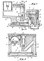
- FIG. 2 there is shown a cross-sectional view taken along the lines 2-2 of Fig. 1, which illustrates additional structure utilized in priming and repriming the fluid system, e.g., following cooling and solidification of the melted ink.
- Hinged door 75 can be opened and has connected thereto a spring 76 which, when rotated clockwise due to opening of the door, presses valve 49 into its downward position. This causes a rubber tip portion 79 of the valve element to close the opening 50, thereby sealing off upper reservoir 44 from the outside and blocking fluid flow from reservoir portion 44 down into the lower reservoir portions 51, 52 and 62.
- a hemispherical bulb 80 made of a flexible rubber-like material is positioned below door 75, such that it is easily accessible to an operator when door 75 is opened.
- Bulb 80 defines an inner space which communicates to a one-way valve 89 positioned directly below the bulb.
- This priming pressure which is suitably of the order of 2 - 3 psi, cannot escape through opening 50, but does find a pathway through filter 54 to the ink maintained in the lower reservoir portion 52 and the sump 62.
- the priming pressure has a pathway through bypass channel 81 which couples into vertical channel 82 leading down into the area above sump 62.
- bypass channel 81 couples into vertical channel 82 leading down into the area above sump 62.
- the operator In operation of the embodiment of Figs. 1 and 2, the operator must take care not to prime excessively and exhaust ink from the system to the point of forcing air up into the ink jet head. Such condition of pushing air into the ink jet head can have very adverse consequences, and indeed can result in complete loss of operation of the apparatus.
- the operator can avoid this by monitoring the visual output from level sensor 63, and terminating the priming operation as soon as a low level indication is provided.
- Level sensor 63 is suitably set to provide a low level indication with a margin of safety so that the priming or repriming operation is terminated safely before air is permitted to pass up through feed tube 68.
- FIG. 3 and 4 there is illustrated diagramatically another preferred embodiment of this invention, wherein the repriming operation is effected automatically.
- the print head and reservoir combination are illustrated at 40, mounted on rails 90.
- the apparatus 40 is transported by a motor, such as a stepper motor as illustrated at 91.
- Ink pellets are inserted through a removable cap or lid 103 and which contains a cartridge 102 which drops a pellet into the reservoir when the cap 103 is screwed into place.
- a pump 95 is mounted on the printing apparatus but off of the rails, such that it is stationary relative to the movable ink jet apparatus 40. This has the substantial advantage of taking the mass of the pump off of the carriage.
- Pump 95 has a connector 97 which terminates in a conical tip or nipple 98.
- Tip 98 is sized to fit into an otherwise normally open port 101 in the side of the housing of the apparatus 40.
- the tapered tip 98 is positioned such that when motor 91 carries apparatus 40 toward the pump, the tapered tip registers with the seals into port 101 to provide an effective air-tight seal.
- motor 91 carries apparatus 40 to the position where the tip 98 is sealingly connected to the apparatus 40, connector 97 being spring mounted to hold tip 98 safely into the port 101. It is noted that in the absence of the connection, port 101 and passage 104 provide an open vent through which atmospheric pressure is maintained above the ink in the reservoir.
- priming is commenced by the operator controlling the motor to carry the apparatus 40 into connecting position with supply tip 98, and pump 95 then automatically provides the desired 2 - 3 psi of priming pressure. While the priming operation goes on, the level signal, as detected by level detector 63 illustrated in Fig. 1, is continuously monitored by control circuit 92. The priming operation is suitably timed to continue for a sufficient time to pass a predetermined amount of ink through the system and out of the jets.
- control circuit 92 causes motor 91 to immediately carry apparatus 40 away from its connected position, thereby terminating the priming operation while a safe amount of the ink is still maintained in the reservoir. The operator then must replace the ink supply before again carrying out a priming operation.
- any of the desired embodiments of this invention it is desirable to turn off the primary heater 59 when the ink jet apparatus is not being used.
- a characteristic of the hot melt type ink is that it degenerates more quickly the longer it is maintained in its molten state, making it practical to permit the bulk of the ink in the reservoir to freeze when the apparatus is not being used.
- heater 59 is turned off during non-use.
- the print head heater 66 is also turned off, such as when power is lost. All of the ink in the reservoir then cools below the freezing temperature, with resultant contraction and depriming of the system. When it is desired to restart operation of the apparatus, it is necessary to reprime the system, due to the fact that the cooling and freezing of the ink in the reservoir has a depriming effect.
- the flow diagram illustrates the steps to carry out the operation of the apparatus disclosed herein.
- the apparatus is turned on as illustrated at 120, followed by the heating of the ink at 121 to convert all of the ink to its liquid phase. Since the ink had been in its frozen or solid phase while the apparatus was unused, the system is deprimed and needs to be reprimed.
- the repriming step is carried out at block 122, and at the same time the ink level is continuously sensed, as by sensor 63 illustrated in Fig. 1. If at any time during the repriming operation the level L of the ink is sensed to be less than the minimum required level Lmin, then the repriming operation is terminated as illustrated at block 123.
- the operator then adds ink as at 124, following which the repriming operation recommences.
- the apparatus can be operated as illustrated at 126.
- the ink level is continually sensed, and if at any time the level L is sensed to be below Lmin, then ink is added as shown at block 127.
- the apparatus is turned off, as illustrated at 128. When both heaters 59 and 66 are turned off, the ink reverts to its solid or frozen state, with consequent depriming of the system.
Abstract
Description
- This invention relates to ink jet apparatus for ejecting droplets of ink, and more particularly, to ink jet apparatus utilizing hot melt ink.
- The use of hot melt ink in ink jet systems, which ink is normally in a solid or frozen state but attains a liquid state or phase when its temperature is raised, has presented a number of advantages to ink jet apparatus. While the use of hot melt ink has presented advantages, it also creates an additional requirement for the design of the apparatus, including a special need for frequent repriming of the system. One of the characteristics of hot melt type ink is that it degenerates faster the longer it is maintained in its liquid phase, with the result that it is advantageous to permit cooling and freezing of the ink when the apparatus is not in use. However, a problem arises from the fact that hot melt ink contracts when it cools to a temperature below the melting point, which contraction of the ink results in depriming of the system. Thus, such hot melt ink apparatus has an increased need for an efficient priming/repriming system.
- According to the invention fromone aspect there is provided a method of operating an ink jet apparatus, said apparatus having an ink supply system for supplying hot melt type ink to be ejected in the form of ink droplets, comprising the steps of: containing said ink in said ink supply system; normally heating all of said ink in said ink supply system when said apparatus is in use to maintain said ink in its melted phase; cooling said ink when'said apparatus is not being used, whereby said ink reverts to its frozen phase, resulting in contraction of said ink and depriming of said apparatus; re-heating said frozen ink to its melted phase when said apparatus is to be put in use again; and repriming said apparatus, before it is put in use again, to eject ink through said supply system and out of said print head.
- According to the invention from another aspect there is provided ink jet apparatus for use with hot melt ink, comprising a print head for ejection of ink droplets, a reservoir for hot melt type ink for supply to said print head, and a heater operable for maintaining ink in said reservoir in its melted phase, said reservoir comprising a housing with a normally open port, closing means for closing said port, and repriming means operable only when said port is closed for providing air pressure into said reservoir whereby said apparatus is preprimed following re-heating of ink that had frozen, to convert said ink back to its melted phase.
- It will therefore be appreciated that preferred embodiments of the invention are capable of providing an ink jet repriming the system after depriming caused by permitting the hot melt ink to cool to its solid state while the apparatus is not in use. It is also possible to provide an efficient, easily operable, and reliable priming system for use with hot melt ink apparatus or an efficient priming system and method for use with hot melt ink jet apparatus with control means to avoid depriming when the apparatus ink level is too low. The ink jet apparatus may be more to provide an efficient priming system and method for an ink jet apparatus utilizing hot melt ink, the apparatus having a movable ink jet head, and with the bulk of the priming system located separately from the moving structure so as to minimize the mass of such moving structure.
- There is disclosed hereinbelow an ink jet apparatus utilizing hot melt ink, and a method of operating same, having a reservoir system for containing ink and a heating system for controlled heating of the ink to its melted phase when the apparatus is in use, and a priming system for applying priming pressure to the reservoir for repriming the system following non-use of the apparatus. Both manual and automatic modes of priming systems are disclosed, along with means for safeguarding against the priming operation when the ink level in the reservoir falls below a predetermined dangerous level.
- The invention will be more fully understood from the following description given by way of example and with reference to the accompanying drawings wherein:-
- Fig. 1 is a side sectional view of one embodiment of this invention, showing a combined reservoir and ink jet head.
- Fig. 2 is a sectional view along lines 2-2 of Fig. 1, of the apparatus of Fig. 1.
- Fig. 3 is a schematic diagram of another arrangement for the priming system.
- Fig. 4 is a sectional view of a portion of the embodiment of Fig. 3, showing the connection of the stationary priming pump with the movable reservoir apparatus.
- Fig. 5 is a flow diagram illustrating the steps of one method of performing this invention.
- Referring first to Figure 1, in the upper left hand corner there is illustrated a
pellet carrier 41 containing anink pellet 42. The pellet is deposited, by means not shown, into anupper reservoir 44 which is formed by asloping base 46 and areservoir cover 47. Thebase 46 is contiguous with and in thermal connection with alower reservoir base 48 which extends across the bottom of the apparatus and which at the right hand side of the figure defines a well orsump 62, as discussed further herein below. Thebase portion 46 andlower reservoir base 48 are integrally constructed of an efficient heat conductive material, suitably a metal such as aluminum, to enable efficient conduction of heat throughout the reservoir system. This enables melting of thepellet 42 after it has dropped onto the top surface ofupper base 46, and also enables efficient and uniform heating of the melted ink that is maintained in the reservoir, including particularly the ink maintained in thewell 62. Pellet 42 contains ink of the hot melt type, and the ink is maintained in the liquid phase at a predetermined normal operating temperature byheater 59 which is illustrated at the bottom of slopedsection 58 ofreservoir base 48. - Referring to the right hand portion of the reservoir as illustrated in Fig. 1, there is shown a
valve 49 which is in its normally open position, in which position it provides a path through anopening 50 for flow of the melted ink down into alower reservoir area 51.Reservoir portion 51 is bounded on its bottom by finemesh screen filter 54, which removes unwanted particulates from the ink. The ink filters throughscreen 54 and passes throughperforation holes 57 ofplate 56, from where it passes by gravity feed down the tilted or slopedportion 58 ofreservoir base 48 into thesump 62. Baffles 53 are shown within the post-filter portion of thereservoir 52, which baffles are designed to minimize the effect of sloshing of the ink in the reservoir which may occur due to movement of the apparatus. Under normal operating conditions, the ink supply is such that the ink level does not rise appreciably abovefilter 54, and thus the ink can be considered to be appreciably limited to residing in thepost-filter portion 52 and thesump portion 62. Sincevalve 49 is normally in its open position, atmospheric pressure is applied to the liquid ink so that the ink inwell 62 is under a pressure head. - A pair of
level detectors sump 62. The detectors are connected, by means not shown, to indicators or automatic means for signalling the ink level, so that additional ink can be supplied to thereservoir 44 when needed by dropping anotherpellet 42 into it. Pressure on the ink withinsump 62, as well as capillary action, draws ink through feed tube orpassage 68, which communicates through a manifold to the input end of eachorifice chamber 70, which chamber terminates in a standard orifice from which ink drops are expelled. As illustrated, a longitudinal transducer, suitably a piezo-electric type transducer 71 is provided. The overall apparatus comprises, at the ink jet head, an array of transducer-chamber combinations, each terminating in an orifice from which ink droplets are ejected, and supplied with ink throughcommon passage 68 and a manifold in communication with each chamber. Thetransducers 71 are under the control of electronic drive circuitry illustrated as mounted on printedcircuit 72, which printed circuit is separated byinsulator 73 from the heat conductiveprint head block 67. - Still referring to Fig. 1, a
second heater 66 is provided in thermal contact withhead element 67, to maintain the temperature of the ink passing up throughfeed tube 68 and into thechambers 70. This heater is normally kept in an operating state at.all times, even when the apparatus is not in use, so as to always maintain ink in a liquid phase throughout the ink jet head and the length offeed tube 68. To render the operation ofheater 66 efficient and independent of theheater 59, inkjet head element 67 is thermally insulated from the mainreservoir housing portions insulator element 65. - Referring to Fig. 2, there is shown a cross-sectional view taken along the lines 2-2 of Fig. 1, which illustrates additional structure utilized in priming and repriming the fluid system, e.g., following cooling and solidification of the melted ink. Hinged
door 75 can be opened and has connected thereto aspring 76 which, when rotated clockwise due to opening of the door, pressesvalve 49 into its downward position. This causes arubber tip portion 79 of the valve element to close theopening 50, thereby sealing offupper reservoir 44 from the outside and blocking fluid flow fromreservoir portion 44 down into thelower reservoir portions valve element 49, ahemispherical bulb 80 made of a flexible rubber-like material is positioned belowdoor 75, such that it is easily accessible to an operator whendoor 75 is opened.Bulb 80 defines an inner space which communicates to a one-way valve 89 positioned directly below the bulb. When and only whendoor 75 is in its opened position, such thatvalve 49 is in its closed position, the operator can squeezebulb 80 and expell air through the one-way valve 89, thus generating an air pressure withinreservoir 44 for priming purposes. This priming pressure, which is suitably of the order of 2 - 3 psi, cannot escape through opening 50, but does find a pathway throughfilter 54 to the ink maintained in thelower reservoir portion 52 and thesump 62. Additionally, the priming pressure has a pathway throughbypass channel 81 which couples intovertical channel 82 leading down into the area abovesump 62. Thus, even iffilter 54 is relatively clogged such that it presents a high impedence to the priming pressure, the priming system is rendered efficient through the bypass channels. The air pressure thus generated pushes ink up throughfeed 68 to purge theink jet chamber 70 and the corresponding orifices. When the priming operation is terminated, the relative vacuum within the space defined bybulb 80 draws air throughvent 87, forcing up theperipheral portion 88 ofvalve 89, to restore substantial atmospheric air pressure within the space of the bulb. - In operation of the embodiment of Figs. 1 and 2, the operator must take care not to prime excessively and exhaust ink from the system to the point of forcing air up into the ink jet head. Such condition of pushing air into the ink jet head can have very adverse consequences, and indeed can result in complete loss of operation of the apparatus. The operator can avoid this by monitoring the visual output from
level sensor 63, and terminating the priming operation as soon as a low level indication is provided.Level sensor 63 is suitably set to provide a low level indication with a margin of safety so that the priming or repriming operation is terminated safely before air is permitted to pass up throughfeed tube 68. - Referring now to Figs. 3 and 4, there is illustrated diagramatically another preferred embodiment of this invention, wherein the repriming operation is effected automatically. The print head and reservoir combination are illustrated at 40, mounted on rails 90. In a typical application, the
apparatus 40 is transported by a motor, such as a stepper motor as illustrated at 91. Ink pellets are inserted through a removable cap orlid 103 and which contains acartridge 102 which drops a pellet into the reservoir when thecap 103 is screwed into place. Apump 95 is mounted on the printing apparatus but off of the rails, such that it is stationary relative to the movableink jet apparatus 40. This has the substantial advantage of taking the mass of the pump off of the carriage. Pump 95 has aconnector 97 which terminates in a conical tip ornipple 98.Tip 98 is sized to fit into an otherwise normallyopen port 101 in the side of the housing of theapparatus 40. Thetapered tip 98 is positioned such that whenmotor 91 carriesapparatus 40 toward the pump, the tapered tip registers with the seals intoport 101 to provide an effective air-tight seal. For a priming or repriming operation,motor 91 carriesapparatus 40 to the position where thetip 98 is sealingly connected to theapparatus 40,connector 97 being spring mounted to holdtip 98 safely into theport 101. It is noted that in the absence of the connection,port 101 andpassage 104 provide an open vent through which atmospheric pressure is maintained above the ink in the reservoir. - In operation of the automatic apparatus of Figs. 3 and 4, priming is commenced by the operator controlling the motor to carry the
apparatus 40 into connecting position withsupply tip 98, and pump 95 then automatically provides the desired 2 - 3 psi of priming pressure. While the priming operation goes on, the level signal, as detected bylevel detector 63 illustrated in Fig. 1, is continuously monitored bycontrol circuit 92. The priming operation is suitably timed to continue for a sufficient time to pass a predetermined amount of ink through the system and out of the jets. However, if at any time during this operation the level signal indicates that the ink level has dropped to the predetermined level,control circuit 92 causes motor 91 to immediately carryapparatus 40 away from its connected position, thereby terminating the priming operation while a safe amount of the ink is still maintained in the reservoir. The operator then must replace the ink supply before again carrying out a priming operation. - In operation of any of the desired embodiments of this invention, it is desirable to turn off the
primary heater 59 when the ink jet apparatus is not being used. A characteristic of the hot melt type ink is that it degenerates more quickly the longer it is maintained in its molten state, making it practical to permit the bulk of the ink in the reservoir to freeze when the apparatus is not being used. Thus,heater 59 is turned off during non-use. Additionally, it will occasionally happen that theprint head heater 66 is also turned off, such as when power is lost. All of the ink in the reservoir then cools below the freezing temperature, with resultant contraction and depriming of the system. When it is desired to restart operation of the apparatus, it is necessary to reprime the system, due to the fact that the cooling and freezing of the ink in the reservoir has a depriming effect. - Referring now to Fig. 5, the flow diagram illustrates the steps to carry out the operation of the apparatus disclosed herein. The apparatus is turned on as illustrated at 120, followed by the heating of the ink at 121 to convert all of the ink to its liquid phase. Since the ink had been in its frozen or solid phase while the apparatus was unused, the system is deprimed and needs to be reprimed. The repriming step is carried out at
block 122, and at the same time the ink level is continuously sensed, as bysensor 63 illustrated in Fig. 1. If at any time during the repriming operation the level L of the ink is sensed to be less than the minimum required level Lmin, then the repriming operation is terminated as illustrated atblock 123. The operator then adds ink as at 124, following which the repriming operation recommences. When the repriming operation is completed, the apparatus can be operated as illustrated at 126. During the operation the ink level is continually sensed, and if at any time the level L is sensed to be below Lmin, then ink is added as shown atblock 127. At the end of operation, the apparatus is turned off, as illustrated at 128. When bothheaters
Claims (13)
Applications Claiming Priority (4)
| Application Number | Priority Date | Filing Date | Title |
|---|---|---|---|
| US06/661,029 US4607266A (en) | 1984-10-15 | 1984-10-15 | Phase change ink jet with independent heating of jet and reservoir |
| US06/661,925 US4658274A (en) | 1984-10-16 | 1984-10-16 | Melt ink jet apparatus with means and method for repriming |
| US661925 | 1984-10-16 | ||
| US661029 | 1991-02-25 |
Publications (2)
| Publication Number | Publication Date |
|---|---|
| EP0178884A2 true EP0178884A2 (en) | 1986-04-23 |
| EP0178884A3 EP0178884A3 (en) | 1988-04-20 |
Family
ID=27098227
Family Applications (1)
| Application Number | Title | Priority Date | Filing Date |
|---|---|---|---|
| EP85307374A Ceased EP0178884A3 (en) | 1984-10-15 | 1985-10-14 | Ink jet apparatus and method of operating the same |
Country Status (1)
| Country | Link |
|---|---|
| EP (1) | EP0178884A3 (en) |
Cited By (5)
| Publication number | Priority date | Publication date | Assignee | Title |
|---|---|---|---|---|
| EP0282327A2 (en) * | 1987-03-11 | 1988-09-14 | Hewlett-Packard Company | Method and apparatus for priming an ink jet pen |
| WO2008006132A1 (en) * | 2006-07-10 | 2008-01-17 | Silverbrook Research Pty Ltd | Inkjet printhead with controlled de-prime |
| US7661803B2 (en) | 2006-07-31 | 2010-02-16 | Silverbrook Research Pty Ltd | Inkjet printhead with controlled de-prime |
| US7841708B2 (en) | 2006-03-03 | 2010-11-30 | Silverbrook Research Pty Ltd | Fludically controlled inkjet printhead |
| CN102555506A (en) * | 2010-11-16 | 2012-07-11 | 施乐公司 | Printing system with selective heater activation to enable ink to flow to printhead |
Citations (3)
| Publication number | Priority date | Publication date | Assignee | Title |
|---|---|---|---|---|
| US4123761A (en) * | 1976-06-07 | 1978-10-31 | Konishiroku Photo Industry Co., Ltd. | Method of purging ink passages of an ink jet recording device |
| US4305701A (en) * | 1977-12-12 | 1981-12-15 | Gould Inc. | Priming apparatus for liquid ink writing instruments |
| EP0097823A2 (en) * | 1982-06-30 | 1984-01-11 | International Business Machines Corporation | Ink jet recording system |
-
1985
- 1985-10-14 EP EP85307374A patent/EP0178884A3/en not_active Ceased
Patent Citations (3)
| Publication number | Priority date | Publication date | Assignee | Title |
|---|---|---|---|---|
| US4123761A (en) * | 1976-06-07 | 1978-10-31 | Konishiroku Photo Industry Co., Ltd. | Method of purging ink passages of an ink jet recording device |
| US4305701A (en) * | 1977-12-12 | 1981-12-15 | Gould Inc. | Priming apparatus for liquid ink writing instruments |
| EP0097823A2 (en) * | 1982-06-30 | 1984-01-11 | International Business Machines Corporation | Ink jet recording system |
Cited By (9)
| Publication number | Priority date | Publication date | Assignee | Title |
|---|---|---|---|---|
| EP0282327A2 (en) * | 1987-03-11 | 1988-09-14 | Hewlett-Packard Company | Method and apparatus for priming an ink jet pen |
| EP0282327A3 (en) * | 1987-03-11 | 1990-05-09 | Hewlett-Packard Company | Method and apparatus for printing an ink jet pen |
| DE8817173U1 (en) * | 1987-03-11 | 1993-09-02 | Hewlett Packard Co | Device for pressurizing an inkjet cartridge |
| US7841708B2 (en) | 2006-03-03 | 2010-11-30 | Silverbrook Research Pty Ltd | Fludically controlled inkjet printhead |
| WO2008006132A1 (en) * | 2006-07-10 | 2008-01-17 | Silverbrook Research Pty Ltd | Inkjet printhead with controlled de-prime |
| US7661803B2 (en) | 2006-07-31 | 2010-02-16 | Silverbrook Research Pty Ltd | Inkjet printhead with controlled de-prime |
| US8459785B2 (en) | 2006-07-31 | 2013-06-11 | Zamtec Ltd | Inkjet printhead with pressure pulse priming |
| CN102555506A (en) * | 2010-11-16 | 2012-07-11 | 施乐公司 | Printing system with selective heater activation to enable ink to flow to printhead |
| CN102555506B (en) * | 2010-11-16 | 2015-04-01 | 施乐公司 | Printing system with selective heater activation to enable ink to flow to printhead |
Also Published As
| Publication number | Publication date |
|---|---|
| EP0178884A3 (en) | 1988-04-20 |
Similar Documents
| Publication | Publication Date | Title |
|---|---|---|
| US4658274A (en) | Melt ink jet apparatus with means and method for repriming | |
| US4791439A (en) | Ink jet apparatus with improved reservoir system for handling hot melt ink | |
| US4539568A (en) | Hot melt ink jet having non-spill reservoir | |
| US5621444A (en) | Controlled heating of solid ink in ink-jet printing | |
| US4593292A (en) | Ink jet apparatus and method of operating ink jet apparatus employing phase change ink melted as needed | |
| EP0338590B1 (en) | Ink jet type recording apparatus and method | |
| EP0178883B1 (en) | Ink jet apparatus and method of operating the same | |
| US4814786A (en) | Hot melt ink supply system | |
| US4994824A (en) | Modal ink jet printing system | |
| US6007193A (en) | Method and apparatus for removing air bubbles from hot melt ink in an ink-jet printer | |
| US5386224A (en) | Ink level sensing probe system for an ink jet printer | |
| EP0273362B1 (en) | Ink jet recording apparatus | |
| US5557305A (en) | Ink jet purging arrangement | |
| EP0181219B1 (en) | Hot melt ink jet apparatus | |
| EP0805034A2 (en) | Ink barrier for Fluid reservoir vacuum or pressure line | |
| US5168285A (en) | Modal ink jet printing system | |
| EP0178884A2 (en) | Ink jet apparatus and method of operating the same | |
| EP0571127A2 (en) | Monolithic thermal ink jet print head for phase-changing ink | |
| US7775651B2 (en) | Ink jet device with a ventilation conduit | |
| EP1775131B1 (en) | Ink jet device with ventilation conduit | |
| JP2573822B2 (en) | Ink jet recording device | |
| JPS60127158A (en) | Ink jet recorder | |
| JPH0149628B2 (en) | ||
| JPH0449051A (en) | Ink jet recorder | |
| JPH03239561A (en) | Ink jet printer |
Legal Events
| Date | Code | Title | Description |
|---|---|---|---|
| PUAI | Public reference made under article 153(3) epc to a published international application that has entered the european phase |
Free format text: ORIGINAL CODE: 0009012 |
|
| AK | Designated contracting states |
Kind code of ref document: A2 Designated state(s): BE CH DE FR GB IT LI LU NL |
|
| PUAL | Search report despatched |
Free format text: ORIGINAL CODE: 0009013 |
|
| RAP1 | Party data changed (applicant data changed or rights of an application transferred) |
Owner name: DATAPRODUCTS CORPORATION |
|
| AK | Designated contracting states |
Kind code of ref document: A3 Designated state(s): BE CH DE FR GB IT LI LU NL |
|
| 17P | Request for examination filed |
Effective date: 19881019 |
|
| 17Q | First examination report despatched |
Effective date: 19900528 |
|
| STAA | Information on the status of an ep patent application or granted ep patent |
Free format text: STATUS: THE APPLICATION HAS BEEN REFUSED |
|
| 18R | Application refused |
Effective date: 19940221 |
|
| RIN1 | Information on inventor provided before grant (corrected) |
Inventor name: DEYOUNG, THOMAS WILLIAM |