EP0178397A2 - Braiding machine - Google Patents
Braiding machine Download PDFInfo
- Publication number
- EP0178397A2 EP0178397A2 EP85109257A EP85109257A EP0178397A2 EP 0178397 A2 EP0178397 A2 EP 0178397A2 EP 85109257 A EP85109257 A EP 85109257A EP 85109257 A EP85109257 A EP 85109257A EP 0178397 A2 EP0178397 A2 EP 0178397A2
- Authority
- EP
- European Patent Office
- Prior art keywords
- braiding
- thread
- bobbin
- machine according
- coils
- Prior art date
- Legal status (The legal status is an assumption and is not a legal conclusion. Google has not performed a legal analysis and makes no representation as to the accuracy of the status listed.)
- Withdrawn
Links
Images


Classifications
-
- D—TEXTILES; PAPER
- D04—BRAIDING; LACE-MAKING; KNITTING; TRIMMINGS; NON-WOVEN FABRICS
- D04C—BRAIDING OR MANUFACTURE OF LACE, INCLUDING BOBBIN-NET OR CARBONISED LACE; BRAIDING MACHINES; BRAID; LACE
- D04C3/00—Braiding or lacing machines
- D04C3/40—Braiding or lacing machines for making tubular braids by circulating strand supplies around braiding centre at equal distances
- D04C3/44—Braiding or lacing machines for making tubular braids by circulating strand supplies around braiding centre at equal distances with means for forming sheds by subsequently diverting various threads using the same guiding means
-
- D—TEXTILES; PAPER
- D04—BRAIDING; LACE-MAKING; KNITTING; TRIMMINGS; NON-WOVEN FABRICS
- D04C—BRAIDING OR MANUFACTURE OF LACE, INCLUDING BOBBIN-NET OR CARBONISED LACE; BRAIDING MACHINES; BRAID; LACE
- D04C3/00—Braiding or lacing machines
- D04C3/48—Auxiliary devices
Definitions
- the invention relates to a braiding machine according to the preamble of claim 1.
- the invention has for its object to design a braiding machine of the type mentioned above so that higher performance can be achieved. Furthermore, the machine, if appropriate after a corresponding modification, should be suitable for the braiding of individual braiding threads or braiding strands which are drawn off from a bobbin in each case.
- the second bobbins are, so to speak, floating on rotating plates, without participating in their own rotation. This is achieved in that coil carriers are provided which are supported on two adjacent rotating plates.
- the rotating plates also serve - as before - to guide the braided thread.
- the braiding threads can be steered with passive devices; but it is also possible to use the known thread levers as active thread guiding devices, which leads to higher machine performance and protects the braided threads during their processing.
- the rotating plates on which the second coils sit can run horizontally or vertically. Accordingly, their drive axis runs vertically or horizontally.
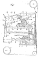
- FIGS. 1 and 2 in which the braiding machine is shown in its essential components.
- An elongated good for example a cable 1 is conveyed from a storage drum 2 along a (vertical) machine axis 3 to a storage drum 4 and is covered with a braiding layer at a braiding point 5.
- a number of single or multiple braiding threads 6 and 7 are used, which run freely from first bobbins 8 and second bobbins 9, respectively.
- eight coils 8 and 9 are provided, however, a different number can also be selected according to the number of braiding threads on the circumference of the cable to be sheathed.
- the coils 8 sit on and run around a first lower coil disk 10, while the second coils 9 are connected to a second upper coil disk 11 and rotate radially inwards relative to the coils 8.
- the lower reel disk has a tubular hub 12 and the upper winding disk a hub 13.
- At the hub 12 is a bevel gear ring 14 and on the hub 13, a K egel leopardradkranz attached 15th
- the hub 12 and thus the lower bobbin wheel 10 are rotatably supported on the base frame of the machine housing via a track bearing 16, and the hub 13 with the upper bobbin wheel 11 is supported on the lower bobbin wheel 10 by means of a support 18, and a further bearing 19 is also provided provided that is supported on a tube 20, which is part of the machine frame.
- the (horizontal) coil disks 10 and 11 can thus rotate about the (vertical) machine axis 3, the coils 8 and 9 being carried along and rotating about the axis 3 .
- the spool disks 10 and 11 are driven in opposite directions to one another, specifically via a bevel pinion 21 which engages in the toothed rings 14, 15 and is connected to a motor 23 via a shaft 22.
- a brake disc 24 is provided which works together with brake shoes, not shown.
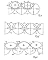
- the braiding threads 6 and 7 have opposite orbits, the orbit of the braiding thread 7 being in a cone jacket, the orbit of the braiding thread 6, however, can be described as an undulated cone jacket.
- this orbit is to be represented as a sinusoidal wave, the maxima coinciding with the position of the braided thread 6, while the minima are indicated with the position 6a.
- the braiding thread 6 thus dances to a certain extent around the braiding thread 7, the path of an ever new braiding thread 7 being crossed because of the counter-rotation of the bobbin disks 10 and 11. This guiding of the braiding thread 6 is carried out by thread guiding devices 30 accomplished, which are now to be described.
- a deflecting roller 32 for the braiding thread 6 running from the respective bobbin 8.
- One end of the thread lever 31 is articulated on a ball bushing 33, while the other end by means of a journal bearing 34 is connected to a handlebar 35.
- the link 35 is connected via a journal bearing 36 to a crank 37, which is driven in rotation around a shaft 38.
- the thread lever 31 and thus the deflection roller 32 swing up and down so that the running braiding thread can take the position 6 or 6a or an intermediate position.
- the shaft 38 is mounted in the tubular hub 12 and is driven by a bevel gear 39 which meshes with a ring gear 40 of the machine frame.
- a corresponding meandering sinus movement can be generated by means of a gear transmission 41, of which only the housing is shown in FIG. 1, inside which planetary and sun gears are located.
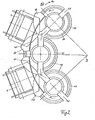
- the thread guiding devices also include rotating bobbin plates 42, the number of which corresponds to the respective number of bobbins 9.
- Each reel disc 42 has two slit-shaped recesses 43, which are opposite each other by 180 * and are used for receiving and guiding the braiding threads. 6
- the bobbin 42 sit on short axes of rotation 44, which are mounted in the upper bobbin wheel 11 and at their lower end carry a gear 45, which mesh with a ring gear 46 which is attached to the lower bobbin wheel 10.
- the plates 42 rotate at a speed of 8 n.
- the translation between the gears 14/21 or 15/21 or. 46/45 is 1: 4.
- the thread guide devices 30 also include thread guide bars 47 and thread plates 48.
- the thread guide bars 47 have a pointed oval outline, as can best be seen in FIG. 6.
- the thread plates 48 are designed similarly.
- the rotating coil plates 42 have annular grooves 49 which serve for the engagement of coil carriers 50.
- the coil carriers 50 are connected to the adjacent coil plates 42 and each carry a coil 9 and a deflection roller 51. As many coils 9 as the coil plates 42 are provided on the circumference of the upper coil disk 11.
- the described connection structure 42, 49, 50 enables the
- the second embodiment of the invention according to FIGS. 3 to 7 has the same basic structure as the first embodiment according to FIGS. 1 and 2. Corresponding parts are given the same reference numerals. However, vertically arranged coil plates 52 are provided. The bobbin plates in turn have cutouts 43 for transferring the braided threads 6. The bobbin holders 50 sit on the bobbin wafers 52 and each hold a bobbin 9. Each bobbin 9 is surrounded by a thread bracket 47 in order to guide the braiding thread 6 of the first bobbin 8 past the second bobbin 9 during their opposite movements without the threads getting tangled . Such a thread path 53 of the thread 6 is shown in FIG. 6.
- the rotation speed of the bobbin plates 52 is k n.
- the braiding thread 6 migrates on the underside of the thread guide bracket 47a and reaches the top of the thread guide bracket during the next quarter turn 47b.
- the Thread 6 then leaves the S pulenteller 52a and enters the receiving slot 43 of the hub 52b which finally the braided 6 passes to the Fadenleitbügel 47c, the thread 6 slides on the underside of this element 47c and enters the next reel disc 52c.
- a drive can also be realized by means of a toothed belt. In any case, however, it can be achieved that not only the first coils 8, but also the second coils 9 are driven without interruption during their circulation.
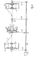
- the machine axis 3-3 is arranged horizontally and, accordingly, the bobbin disks 10 and 11 are vertical.
- the cable 1 is removed from the storage drum 2 by means of a rotating unwinding arm 60.
- a ramp take-off device 65 determines the throughput speed of the cable 1.
- the take-up drum 4 is loaded with a rotating winding arm 61.
- the motor 23 drives the shaft 22, which in turn uses the toothed belt ratios 66, 67, 68, 69 to unwind and Drive winding arms 60, 61 as well as the caterpillar take-off device 65 at the speed n and the bobbin wheel 10 at the speed 2n, while the bobbin wheel 11 remains stationary, that is to say it stands still.
- the bobbin 42 are driven to enable the braiding threads 6 to cross the path of the braiding threads 7, as explained with reference to the paths 53 and 63 (FIGS. 4 and 6).
- the drive design can be based on the relative rotation between the spool disks 10 and 11, as described with reference to FIG. 1.
- the thread lever 31 can also be driven.
- the advantage of the embodiment according to FIG. 10 is that the coil plates 42 are not subject to any additional centrifugal forces which are generated by the rotation of the coil disk 11 in the previous embodiments.
- the rotation of the first coil disk 10 is twice as large in order to arrive at the relative movement of 2n between the two coil disks 10 and 11.
Abstract
Description
Die Erfindung bezieht sich auf eine Flechtmaschine nach dem Oberbegriff des Anspruchs 1.The invention relates to a braiding machine according to the preamble of claim 1.
Bei derartigen, in der Praxis seit Jahrzehnten anzutreffenden Flechtmaschinen sitzen die zweiten Spulen auf einer Führung der ersten Spulenscheibe und werden gegenläufig zu dieser mittels Zahnsegmenten angetrieben, die nacheinander mit einer Mehrzahl von Ritzeln in Eingriff kommen, welche auf einem Zahnkranz ablaufen. Dieses Antriebsprinzip mit fliegendem Wechsel des Antriebs zwischen benachbarten Ritzeln ist insofern ungünstig, als damit keine sehr hohen Antriebsgeschwindigkeiten möglich sind. Ein weiterer Nachteil der bekannten Maschine besteht darin, daß die Flechtung jeweils nur mit zwei nebeneinander liegenden Flechtfäden möglich ist.In braiding machines of this type, which have been found in practice for decades, the second coils sit on a guide of the first coil disk and are driven in opposite directions by means of toothed segments which engage one after the other with a plurality of pinions which run on a ring gear. This drive principle with a flying change of the drive between adjacent pinions is disadvantageous in that it does not allow very high drive speeds. Another disadvantage of the known machine is that the braiding is only possible with two adjacent braiding threads.
Der Erfindung liegt die Aufgabe zugrunde, eine Flechtmaschine der eingangs angegebenen Art so auszubilden, daß damit höhere Leistungen erzielt werden können. Ferner soll die Maschine, gegebenenfalls nach entsprechendem Umbau, für das Flechten von einzelnen Flechtfäden oder Flechtsträngen, die von jeweils einer Spule abgezogen werden, geeignet sein.The invention has for its object to design a braiding machine of the type mentioned above so that higher performance can be achieved. Furthermore, the machine, if appropriate after a corresponding modification, should be suitable for the braiding of individual braiding threads or braiding strands which are drawn off from a bobbin in each case.
Die gestellte Aufgabe wird aufgrund der Maßnahmen des Anspruchs 1 gelöst.The task is solved on the basis of the measures of claim 1.
Bei der neuen Flechtmaschine sind die zweiten Spulen gewissermaßen fliegend auf rotierenden Tellern gelagert, ohne deren Eigenrotation mitzumachen. Dies gelingt dadurch, daß Spulenträger vorgesehen sind, die sich an zwei benachbarten, rotierenden Tellern abstützen. Die rotierenden Teller dienen außerdem - wie bisher auch - der Flechtfadenführung. Die Flechtfäden könen mit passiven Einrichtungen gelenkt werden; es ist aber auch möglich, die an sich bekannten Fadenhebel als aktive Fadenleiteinrichtungen zu benutzen, wodurch man auf höhere Maschinenleistung kommt und die Flechtfäden bei ihrer Verarbeitung schont.In the new braiding machine, the second bobbins are, so to speak, floating on rotating plates, without participating in their own rotation. This is achieved in that coil carriers are provided which are supported on two adjacent rotating plates. The rotating plates also serve - as before - to guide the braided thread. The braiding threads can be steered with passive devices; but it is also possible to use the known thread levers as active thread guiding devices, which leads to higher machine performance and protects the braided threads during their processing.
Die rotierenden Teller, auf denen die zweiten Spulen sitzen, können waagerecht oder senkrecht verlaufen. Demgemäß läuft ihre Antriebsachse senkrecht oder waagerecht.The rotating plates on which the second coils sit can run horizontally or vertically. Accordingly, their drive axis runs vertically or horizontally.
Zwei Ausführungsformen der erfindungsgemäßen Flechtmaschine werden anhand der Zeichnung beschrieben. Dabei zeigt:
- Fig. 1 einen senkrechten Schnitt durch die Hälfte der ersten Ausführungsform mit waagerechten Spulentellern,
- Fig. 2 eine Teilansicht entsprechend Pfeil II in Fig. 1, in vergrößertem Maßstab gegenüber Fig. 1,
- Fig. 3 eine Teilansicht von oben einer zweiten Ausführungsform mit senkrechtem Spulenteller,
- Fig. 4 eine Ansicht entsprechend Pfeil IV in Fig.3 in einer abgewickelten Darstellung,
- Fig. 5 einen Schnitt entlang der Linie V-V in Fig. 3,
- Fig. 6 einen Schnitt entlang der Linie VI-VI in Fig. 3,
- Fig. 7 einen Schnitt entlang der Linie VII-VII in Fig . 3,
- Fig. 8 einen Fadenheber, geschnitten,
- Fig. 9 den Fadenheber in der Ansicht und
- Fig. 10 eine dritte Ausführungsform mit senkrechten Spulenscheiben.
- 1 is a vertical section through half of the first embodiment with horizontal bobbins,
- 2 is a partial view according to arrow II in FIG. 1, on an enlarged scale compared to FIG. 1,
- 3 is a partial top view of a second embodiment with a vertical bobbin;
- 4 shows a view according to arrow IV in FIG. 3 in a developed view,
- 5 shows a section along the line VV in FIG. 3,
- 6 shows a section along the line VI-VI in FIG. 3,
- 7 shows a section along the line VII-VII in FIG. 3,
- 8 a thread lifter, cut,
- Fig. 9 the thread lifter in the view and
- Fig. 10 shows a third embodiment with vertical coil disks.
Es wird Bezug auf Fig. 1 und 2 genommen,in welchen die Flechtmaschine in ihren wesentlichen Komponenten dargestellt ist. Ein längliches Gut, z.B.ein Kabel 1, wird von einer Vorratstrommel 2 entlang einer (vertikalen) Maschinenachse 3 zu einer Vorratstrommel 4 gefördert und dabei an einem Flechtpunkt 5 mit einer Flechtschicht ummantelt. Es wird eine Anzahl von einfachen oder mehrfachen Flechtfäden 6 und 7 verwendet, die von ersten Spulen 8 bzw. zweiten Spulen 9 frei ablaufen. Im vorliegenden Ausführungsbeispiel sind acht Spulen 8 bzw. 9 vorgesehen, es kann aber auch eine andere Anzahl gewählt werden entsprechend der Anzahl der Flechtfäden am Umfang des zu ummantelnden Kabels. Die Spulen 8 sitzen auf einer ersten unteren Spulenscheibe 10 und laufen mit dieser um, während die zweiten Spulen 9 mit einer zweiten oberen Spulenscheibe 11 verbunden sind und relativ zu den Spulen 8 radial einwärts umlaufen. Die untere Spulenscheibe besitzt eine rohrförmige Nabe 12 und die obere Spulenscheibe eine Nabe 13. An der Nabe 12 ist ein Kegelzahnradkranz 14 und an der Nabe 13 ein Kegelzahnradkranz 15 befestigt. Die Nabe 12 und damit die untere Spulenscheibe 10 sind über ein Spurlager 16 am Grundgestell des Maschinengehäuses drehbar gelagert, und die Nabe 13 mit der oberen Spulenscheibe 11 stützt sich über ein Auflager 18 an der unteren Spulenscheibe 10 ab, ferner ist noch ein weiteres Lager 19 vorgesehen, das sich an einem Rohr 20 abstützt, welches Teil des Maschinengestells ist.Die (waagerechten) Spulenscheiben 10 und 11 können sich somit um die (senkrechte) Maschinenachse 3 drehen, wobei die Spulen 8 und 9 mitgenommen werden und um die Achse 3 kreisen. Der Antrieb der Spulenscheiben 10 und 11 erfolgt gegenläufig zueinander , und zwar über ein Kegelritzel 21, welches in den Zahnkränzen 14, 15 eingreift und über eine Welle 22 mit einem Motor 23 verbunden ist. Um die Maschine schneller anhalten zu können, ist eine Bremsscheibe 24 vorgesehen, die mit nicht dargestellten Bremsbacken zusammenarbeitet.Reference is made to FIGS. 1 and 2, in which the braiding machine is shown in its essential components. An elongated good, for example a cable 1, is conveyed from a
Wie bereits erwähnt, nehmen die Flechtfäden 6 und 7 gegenläufige Umlaufbahnen ein, wobei die Umlaufbahn des Flechtfadens 7 in einem Kegelmantel liegt, die Umlaufbahn des Flechtfadens 6 dagegen als ein ondulierter Kegelmantel beschrieben werden kann. In einer Abwicklung ist diese Umlaufbahn als sinusförmige Welle darzustellen, wobei die Maxima mit der eingezeichneten Lage des Flechtfadens 6 zusammenfallen, während die Minima mit der eingezeichneten Lage 6a angedeutet sind. Der Flechtfaden 6 tanzt somit gewissermaßen um den Flechtfaden 7 herum, wobei wegen der Gegenläufigkeit der Spulenscheiben 10 und 11 die Bahn eines immer neuen Flechtfadens 7 gekreuzt wird. Diese Führung des Flechtfadens 6 wird durch Fadenleiteinrichtungen 30 bewerkstelligt, die nunmehr zu beschreiben sind.As already mentioned, the
Auf einem Fadenhebel 31 (s. auch Fig. 8 und 9) sitzt eine Umlenkrolle 32 für den von der jeweiligen Spule 8 ablaufenden Flechtfaden 6. Das eine Ende des Fadenhebels 31 ist an einer Kugelbuchse 33 angelenkt, während das andere Ende mittels eines Zapfenlagers 34 mit einem Lenker 35 verbunden ist. Der Lenker 35 steht über ein Zapfenlager 36 mit einer Kurbel 37 in Verbindung, die über eine Welle 38 umlaufend angetrieben wird. Der Fadenhebel 31 und damit die Umlenkrolle 32 schwingen nach oben und unten , so daß der ablaufende Flechtfaden die Position 6 oder 6a bzw. eine Zwischenposition einnehmen kann. Die Welle 38 ist in der rohrförmigen Nabe 12 gelagert und wird über ein Kegelzahnrad 39 angetrieben, das mit einem Zahnkranz 40 des Maschinengestells kämmt.On a thread lever 31 (see also FIGS. 8 and 9) there is a
Wenn man eine längere Verweildauer des Flechtfadens in der Extremlage 6 bzw. 6a wünscht, kann man eine entsprechende mäanderförmige Sinusbewegung mittels eines Zahnradgetriebes 41 erzeugen, von dem in Fig. 1 nur das Gehäuse dargestellt ist, in dessen Innerem sich Planeten-und Sonnenräder befinden.If a longer dwell time of the braiding thread in the
Zu den Fadenleiteinrichtungen gehören noch rotierende Spulenteller 42 , deren Anzahl der jeweiligen Anzahl der Spulen 9 entspricht. Jeder Spulenteller 42 besitzt zwei schlitzförmige Aussparungen 43, die sich um 180* gegenüberstehen und zur Aufnahme und Führung der Flechtfäden 6 dienen. Wenn sich die schlitzförmigen Aussparungen 43 zweier benachbarter Spulenteller 42 begegnen, tritt der Flechtfaden 6 von dem einen zum anderen Spulenteller 42 über. Die Spulenteller 42 sitzen an kurzen Drehachsen 44, die in der oberen Spulenscheibe 11 gelagert sind und an ihrem unteren Ende ein Zahnrad 45 tragen, welche mit einem Zahnkranz 46 kämmen, der an der unteren Spulenscheibe 10 befestigt ist. Wenn die Anzahl der ersten oder zweiten Spulen acht beträgt, insgesamt also 16 Spulen vorhanden sind, und eine Umlaufgeschwindigkeit n der unteren Spulenscheibe 10 angenommen wird, dann rotieren die Teller 42 mit einer Geschwindigkeit von 8 n. Die Übersetzung zwischen den Zahnrädern 14/21 bzw. 15/21 bwz. 46/45 beträgt jeweils 1:4 .The thread guiding devices also include rotating
Zu den Fadenleiteinrichtungen 30 gehören noch Fadenleitbügel 47 und Fadenbleche 48. Die Fadenleitbügel 47 besitzen einen zugespitzt ovalen Umriß, wie am besten aus Fig. 6 ersichtlich. Die Fadenbleche 48 sind ähnlich gestaltet.The
Die rotierenden Spulenteller 42 weisen ringförmige Nuten 49 auf, die zum Eingriff von Spulenträgern 50 dienen. Die Spulenträger 50 sind mit den benachbarten Spulentellern 42 verbunden und tragen jeweils eine Spule 9 sowie eine Umlenkrolle 51. Es sind ebenso viele Spulen 9 wie Spulenteller 42 an Umfang der oberen Spulenscheibe 11 vorgesehen. Die beschriebene Verbindungskonstruktion 42, 49, 50 ermöglicht es, dieThe rotating
Spulen 9 durch Antrieb über die obere Spulenscheibe 11 in einer Kreisbahn anzutreiben, ohne daß eine Antriebsunterbrechung auftritt.To drive
Die zweite Ausführungsform der Erfindung gemäß den Fig. 3 bis 7 hat den gleichen prinzipiellen Aufbau wie die erste Ausführungsform nach Fig. 1 und 2. Sich entsprechende Teile werden mit den gleichen Bezugszeichen belegt. Es sind jedoch senkrecht angeordnete Spulenteller 52 vorgesehen. Die Spulenteller weisen wiederum Aussparungen 43 zur Überleitung der Flechtfäden 6 auf. Auf den Spulentellern 52 sitzen die Spulenträger 50 und halten jeweils eine Spule 9. Jede Spule 9 ist von einem Fadenbügel 47 umgeben, um den Flechtfaden 6 der ersten Spule 8 an der zweiten Spule 9 bei deren gegenläufigen Bewegungen vorbeizuführen, ohne daß sich die Fäden verheddern. In Fig. 6 ist eine derartige Fadenbahn 53 des Fadens 6 eingezeichnet. Wenn eine Anzahl k der Spulen 9 angenommen wird, beträgt die Rotationsgeschwindigkeit der Spulenteller 52 k n. Während einer Vierteldrehung des Spulentellers 52a in Fig. 6 wandert der Flechtfaden 6 an der Unterseite des Fadenleitbügels 47a und gelangt während der nächsten Vierteldrehung auf die Oberseite des Fadenleitbügels 47b. Der Faden 6 verläßt dann den Spulenteller 52a und tritt in den Aufnahmeschlitz 43 des Spulentellers 52b ein, der schließlich den Flechtfaden 6 an den Fadenleitbügel 47c übergibt, wobei der Faden 6 an der Unterseite dieses Elements 47c gleitet und in den nächsten Spulenteller 52c eintritt.The second embodiment of the invention according to FIGS. 3 to 7 has the same basic structure as the first embodiment according to FIGS. 1 and 2. Corresponding parts are given the same reference numerals. However, vertically arranged
Wenn die Teller 52 mit der Geschwindigkeit kn rotieren und die Fadenhebel 31 mit 1/2 kn nur halb so schnell laufen, ist es auch möglich, jeweils zwei Fadenleitbügel 47 mit einer entsprechenden Unlaufbahn 63(Fig.4) des ersten Flechtfadens 6 zu umfassen, was zu einer Flechtung führt, bei der jeweils zwei erste Fäden 6 und zwei zweite Fäden 7 nebeneinander im Geflecht vorhanden sind. Dies entspricht den bisher üblichen Geflechten. Das anhand von Fig. 6 erläuterte Flechtverfahren, bei dem sich jeweils ein erster Flechtfaden mit einem zweiten Flechtfaden abwechselt, stellt somit etwas Besonderes dar.If the
Fig. 7 zeigt den Antrieb des Spulentellers 52. Wie ersichtlich, weist dieser eine waagerechte Antriebsachse oder Welle 54 auf, an deren antriebbseitigen Ende ein Kegelzahnrad 55 angebracht ist, welches mit einem Kegelzahnrad 56 mit einem Übersetzungsverhältnis I = 1:4 kämmt. Dieses Übersetzungsverhältnis führt zu der Flechtbahn 53 (Fig. 6).Fig. 7 shows the drive of the
Anstelle der dargestellten Zahnradübersetzungen kann man auch einen Antrieb mittels Zahnriemen verwirklichen. In jedem Fall kann man aber erreichen, daß nicht nur die ersten'.Spulen 8, sondern auch die zweiten Spulen 9 unterbrechungslos bei ihrem Umlauf angetrieben werden.Instead of the gear ratios shown, a drive can also be realized by means of a toothed belt. In any case, however, it can be achieved that not only the
Bei der Flechtmaschine in Fig. 10 ist die Maschinenachse 3-3 waagrecht angeordnet und demgemäß die Spulenscheiben 10 und 11 senkrecht. Das Kabel 1 wird der Vorratstrommel 2 mittels eines rotierenden Abwickelarms 60 entnommen. Eine Rampenabzugseinrichtung 65 bestimmt die Durchlaufgeschwindigkeit des Kabels 1. Die Aufnahmetrommel 4 wird mit einem rotierenden Aufwickelarm 61 beschickt. Der Motor 23 treibt die Welle 22 an, welche wiederum über Zahnriemenübersetzungen 66, 67, 68, 69 die Abwickel- und Aufwickelarme 60, 61 sowie die Raupenabzugseinrichtung 65 mit der Drehzahl n und die Spulenscheibe 10 mit der Drehzahl 2n antreiben, während die Spulenscheibe 11 stationär bleibt, also steht. Dagegen werden die Spulenteller 42 angetrieben, um den Flechtfäden 6 das Überkreuzen der Bahn der Flechtfäden 7 zu ermöglichen, wie mit Bezug auf die Bahnen 53 und 63 (Fig. 4 und 6) erläutert. Die Antriebskonstruktion kann auf der Relativdrehung zwischen den Spulenscheiben 10 und 11 beruhen, wie dies mit Bezug auf Fig. 1 beschrieben wurde. Ebenso können die Fadenhebel 31 angetrieben werden.In the braiding machine in Fig. 10, the machine axis 3-3 is arranged horizontally and, accordingly, the
Der Vorteil der Ausführungsform nach Fig. 10 besteht darin, daß die Spulenteller 42 keinen zusätzlichen Fliehkräften unterliegen, die von der Rotation der Spulenscheibe 11 in den vorhergehenden Ausführungsformen erzeugt werden. Andererseits ist der Umlauf der ersten Spulenscheibe 10 doppelt so groß, um auf die Relativbewegung von 2n zwischen den beiden Spulenscheiben 10 und 11 zu kommen.The advantage of the embodiment according to FIG. 10 is that the
Es ist auch möglich, die Spulenscheiben 10 und 11 gegeneinander rotieren zu lassen, wobei die absolute Geschwindigkeit der einzelnen Spulenscheiben unterschiedlich sein kann, denn es kommt nur auf die Einhaltung der Relativgeschwindigkeit von 2n an. Man kann somit einen Kompromiß hinsichtlich der Herabsetzung der absoluten Umlaufgeschwindigkeit und der Fliehkräfte an den Spulentellern 42 erzielen.It is also possible to rotate the
Claims (10)
gekennzeichnet durch folgende Maßnahmen:
die Teller (42, 52) sind am Umfang einer zweiten Spulenscheibe (11) verteilt angeordnet und drehbar gelagert; je zwei benachbarte Teller (42, 52) bilden die Lagerstützen für einen Spulenträger (50), an dem jeweils eine der zweiten Spulen (9) drehbar gelagert ist; die zweite Spulenscheibe (11) führt eine gegenläufige Relativbeweigung zur ersten Spulenscheibe (10) aus.1. Braiding machine, in particular for producing textile and wire braids and for braiding round materials, such as cables and hoses, with textile threads, copper and steel wires, with the following features: a first bobbin wheel (10) is about a machine axis (3) rotatably mounted and supports - distributed around the circumference - a first arrangement with a number (n) of first coils (8), which according to a drive (12, 14, 21, 22, 23, 69) around the machine axis (3 ) circle;
characterized by the following measures:
the plates (42, 52) are distributed around the circumference of a second coil disk (11) and are rotatably supported; Two adjacent plates (42, 52) each form the bearing supports for a coil carrier (50), on each of which one of the second coils (9) is rotatably mounted; the second coil disk (11) executes an opposite movement relative to the first coil disk (10).
Applications Claiming Priority (2)
| Application Number | Priority Date | Filing Date | Title |
|---|---|---|---|
| DE19848422140 DE8422140U1 (en) | 1984-07-25 | 1984-07-25 | BRAIDING MACHINE |
| DE8422140U | 1984-07-25 |
Publications (2)
| Publication Number | Publication Date |
|---|---|
| EP0178397A2 true EP0178397A2 (en) | 1986-04-23 |
| EP0178397A3 EP0178397A3 (en) | 1987-03-04 |
Family
ID=6769174
Family Applications (1)
| Application Number | Title | Priority Date | Filing Date |
|---|---|---|---|
| EP85109257A Withdrawn EP0178397A3 (en) | 1984-07-25 | 1985-07-24 | Braiding machine |
Country Status (2)
| Country | Link |
|---|---|
| EP (1) | EP0178397A3 (en) |
| DE (1) | DE8422140U1 (en) |
Cited By (1)
| Publication number | Priority date | Publication date | Assignee | Title |
|---|---|---|---|---|
| EP0341677A2 (en) * | 1988-05-11 | 1989-11-15 | Dhw Draht Und Extrusion Gmbh | Braiding machine |
Families Citing this family (1)
| Publication number | Priority date | Publication date | Assignee | Title |
|---|---|---|---|---|
| US4535673A (en) * | 1984-11-20 | 1985-08-20 | James F. Karg | Apparatus for rotation of carriers for a strand supply bobbin |
Citations (6)
| Publication number | Priority date | Publication date | Assignee | Title |
|---|---|---|---|---|
| GB1155779A (en) * | 1966-09-29 | 1969-06-18 | Elitex Zavody Textilniho | Improvements in or relating to Braiding Machines |
| GB1162262A (en) * | 1965-12-03 | 1969-08-20 | Elitex Zavody Textilniho | Improvements in or relating to Tubular Goods Braiding Machine |
| US4034643A (en) * | 1976-11-01 | 1977-07-12 | Rockwell International Corporation | Bobbin drive mechanism for a rotary braider |
| US4130046A (en) * | 1978-02-15 | 1978-12-19 | Vincent Sokol | Braiding machine with continuous tension filament control |
| GB2062022A (en) * | 1979-10-26 | 1981-05-20 | Wabing Srl | Braided stranded rope forming machine |
| US4372191A (en) * | 1982-03-12 | 1983-02-08 | Rockwell International Corp. | Rotary braiding machine |
-
1984
- 1984-07-25 DE DE19848422140 patent/DE8422140U1/en not_active Expired
-
1985
- 1985-07-24 EP EP85109257A patent/EP0178397A3/en not_active Withdrawn
Patent Citations (6)
| Publication number | Priority date | Publication date | Assignee | Title |
|---|---|---|---|---|
| GB1162262A (en) * | 1965-12-03 | 1969-08-20 | Elitex Zavody Textilniho | Improvements in or relating to Tubular Goods Braiding Machine |
| GB1155779A (en) * | 1966-09-29 | 1969-06-18 | Elitex Zavody Textilniho | Improvements in or relating to Braiding Machines |
| US4034643A (en) * | 1976-11-01 | 1977-07-12 | Rockwell International Corporation | Bobbin drive mechanism for a rotary braider |
| US4130046A (en) * | 1978-02-15 | 1978-12-19 | Vincent Sokol | Braiding machine with continuous tension filament control |
| GB2062022A (en) * | 1979-10-26 | 1981-05-20 | Wabing Srl | Braided stranded rope forming machine |
| US4372191A (en) * | 1982-03-12 | 1983-02-08 | Rockwell International Corp. | Rotary braiding machine |
Cited By (2)
| Publication number | Priority date | Publication date | Assignee | Title |
|---|---|---|---|---|
| EP0341677A2 (en) * | 1988-05-11 | 1989-11-15 | Dhw Draht Und Extrusion Gmbh | Braiding machine |
| EP0341677A3 (en) * | 1988-05-11 | 1991-11-21 | Dhw Draht Und Extrusion Gmbh | Braiding machine |
Also Published As
| Publication number | Publication date |
|---|---|
| DE8422140U1 (en) | 1984-10-18 |
| EP0178397A3 (en) | 1987-03-04 |
Similar Documents
| Publication | Publication Date | Title |
|---|---|---|
| DE2743893C3 (en) | Circular braiding machine | |
| DE2231533C3 (en) | Basket stranding machine with several stranding devices arranged in a stranding basket | |
| DE2522595B2 (en) | DEVICE FOR STRINGING STRINGING ELEMENTS FOR MESSAGE CABLES | |
| DE3541029A1 (en) | BRAIDED OR CLAMPING MACHINE | |
| EP2284304B1 (en) | Sample warper and method for creating a sample warp | |
| DE19605924C2 (en) | Additional device for a device for producing short chains | |
| DE2006153C3 (en) | Device for producing wire strands for electrical cables | |
| DE1134130B (en) | Method for layer stranding of telecommunication cable stranding elements | |
| DE1191197B (en) | Device for supplying take-up reels and drums for electrical wires and cables | |
| DD226604B1 (en) | DEVICE FOR PRODUCING MULTILAYER STEEL WIRE LIGHTS | |
| DE4211735A1 (en) | Method and device for producing high-strength steel wire strands | |
| EP0178397A2 (en) | Braiding machine | |
| DE3023257C2 (en) | ||
| DE2615275A1 (en) | Stranding machine for making cables - has guiding disc and perforated disc with perforated ring around it, driven by motor | |
| DE3636638A1 (en) | Apparatus for the stranding round of a material string | |
| DE1510092C (en) | Stranding machine for the production of several superimposed layers of wires or strands with alternating lay directions in one pass | |
| DE2447659A1 (en) | STRINGING MACHINE, IN PARTICULAR FOR THE PRODUCTION OF ELECTRICAL CABLES AND LINES | |
| DD301296A7 (en) | Strand guiding device, in particular for braiding machines | |
| EP0341677A2 (en) | Braiding machine | |
| DE1685851B2 (en) | DEVICE FOR RIVERING THE STRINGING MATERIAL ON A STRINGING MACHINE | |
| DE2116334C3 (en) | Stranding machine for the production of multi-core electrical cables | |
| DE19501001C2 (en) | Device for reversing stranding of stranding elements | |
| DE3810876C2 (en) | ||
| DE2250215C3 (en) | Reverse drive for a core bobbin mounted in the rotor of a high-speed stranding machine | |
| DE2115349A1 (en) | Twisting array - to route rope strands in a course parallel to the machine axis |
Legal Events
| Date | Code | Title | Description |
|---|---|---|---|
| PUAI | Public reference made under article 153(3) epc to a published international application that has entered the european phase |
Free format text: ORIGINAL CODE: 0009012 |
|
| AK | Designated contracting states |
Kind code of ref document: A2 Designated state(s): AT BE CH DE FR GB IT LI LU NL SE |
|
| RBV | Designated contracting states (corrected) |
Designated state(s): CH DE FR LI NL |
|
| PUAL | Search report despatched |
Free format text: ORIGINAL CODE: 0009013 |
|
| AK | Designated contracting states |
Kind code of ref document: A3 Designated state(s): CH DE FR LI NL |
|
| STAA | Information on the status of an ep patent application or granted ep patent |
Free format text: STATUS: THE APPLICATION IS DEEMED TO BE WITHDRAWN |
|
| 18D | Application deemed to be withdrawn |
Effective date: 19870905 |