EP0177942A2 - Correlation detection type ultrasound blood flowmeter - Google Patents
Correlation detection type ultrasound blood flowmeter Download PDFInfo
- Publication number
- EP0177942A2 EP0177942A2 EP85112767A EP85112767A EP0177942A2 EP 0177942 A2 EP0177942 A2 EP 0177942A2 EP 85112767 A EP85112767 A EP 85112767A EP 85112767 A EP85112767 A EP 85112767A EP 0177942 A2 EP0177942 A2 EP 0177942A2
- Authority
- EP
- European Patent Office
- Prior art keywords
- sound
- blood
- beams
- echo signals
- flowmeter
- Prior art date
- Legal status (The legal status is an assumption and is not a legal conclusion. Google has not performed a legal analysis and makes no representation as to the accuracy of the status listed.)
- Granted
Links
Images


Classifications
-
- G—PHYSICS
- G01—MEASURING; TESTING
- G01S—RADIO DIRECTION-FINDING; RADIO NAVIGATION; DETERMINING DISTANCE OR VELOCITY BY USE OF RADIO WAVES; LOCATING OR PRESENCE-DETECTING BY USE OF THE REFLECTION OR RERADIATION OF RADIO WAVES; ANALOGOUS ARRANGEMENTS USING OTHER WAVES
- G01S15/00—Systems using the reflection or reradiation of acoustic waves, e.g. sonar systems
- G01S15/88—Sonar systems specially adapted for specific applications
- G01S15/89—Sonar systems specially adapted for specific applications for mapping or imaging
- G01S15/8906—Short-range imaging systems; Acoustic microscope systems using pulse-echo techniques
- G01S15/8979—Combined Doppler and pulse-echo imaging systems
-
- A—HUMAN NECESSITIES
- A61—MEDICAL OR VETERINARY SCIENCE; HYGIENE
- A61B—DIAGNOSIS; SURGERY; IDENTIFICATION
- A61B8/00—Diagnosis using ultrasonic, sonic or infrasonic waves
- A61B8/06—Measuring blood flow
Definitions
- the present invention relates to an ultrasound blood flowmeter of a correlation detection type.
- a Doppler effect type blood flowmeter is used in the measurement of blood flow speed.
- the speed measured by such a flowmeter is merely the component of blood flow velocity in the direction of a sound beam used in the measurement.
- speed (velocity component) perpendicular to the sound-beam cannot be measured by a Doppler effect type blood flowmeter.
- a correlation detection type blood flowmeter can measure the speed of a blood flow perpendicular to a measurement sound-beam.
- the correlation detection type blood flowmeter was invented by the inventor of the present invention and described in Japanese laid-open patent No. 58-71464 in 1983. Before discussing the present invention, that previously proposed correlation detection type blood flowmeter will be explained with reference to Fiqs. 1 and 2, to facilitate understanding of the present invention.
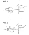
- Fig. 1 is a schematic diagram illustrating the relationship between sound-beams (B 1 and B 2 ) formed by the previously proposed correlation detection type blood flowmeter 101 (blood flowmeter 101) and a blood flow 301 or 302 located in a human body 300.
- the blood flowmeter 101 comprises an ultrasound transducer (transducer) TD placed on a surface 303 of the body 300; transducer TD forms dual sound-beams B 1 and B 2 for measuring the speed of blood flow 301, which flows almost perpendicularly with respect to sound-beams B 1 and B 2 ; transducer TD sends pulsed or burst ultrasound waves (burst sound waves) into human body 300 along sound-beams B 1 and B 2 and receives echo signals arising from reflections of the sound-beams by substances located along sound-beams B 1 and B 2 .
- transducer TD sends pulsed or burst ultrasound waves (burst sound waves) into human body 300 along sound-beams B 1 and B 2 and receives echo signals arising from reflections of the sound-beams by substances located along sound-beams B 1 and B 2 .
- SV 11 and SV 12 are called sample volumes and they relate to sound-beams B 1 and B 2 respectively.
- Sample volumes SV 11 and SV 12 are equally positioned (equally distant) from transducer TD. The location of the flowing blood is determined by other ultrasound imaging means, and the positions of sample volumes SV 11 and SV 12 are adjusted so that blood flow 301 is caught by (lies within) those sample volumes SV 11 and SV12.
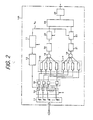
- Fig. 2 is a schematic block diagram of blood flowmeter 101.
- 13 is an ultrasound transducer which corresponds to transducer TD in Fig. 1.
- Transducer 13 is a multi array type ultrasound transducer which consists of a plurality of transducer elements and operates rather like the familiar phased array antenna of a radar system.
- blood flowmeter 101 may operate in two modes: a scanning mode and a focusing mode.
- the former mode is used for providing ultrasound imagery, such as B-mode imagery, and the latter is used for measuring blood speed.
- a change from one mode to the other can be easily effected by electronic means.
- Fig. 2 relates to the focusing mode in which two focused sound-beams B 1 and B 2 are formed.
- a blood flowmeter operates in combination with a unit for providing the scanning mode, but that is omitted in Fig. 2.
- a control unit 11 generates timing and sampling control signals.
- the timing signal is for controlling transducer 13 and a switching circuit 14, and the sampling control signal is for controlling sample-and-hold (S-H) circuits 22 and 23.
- a drive unit 12 Under the control of control unit 11, a drive unit 12 outputs driving pulses for driving transducer 13 to send burst sound waves out from the transducer elements of transducer 13; the generated driving pulses synchronize with the timing signals from control unit 11.
- the switching unit 14 is for switching transducer 13 so as to send the burst sound waves and to receive reflected sound waves under the control of control unit 11.
- switching unit 14 is turned to T (Fig. 2 shows this case) the transducer elements send the burst sound waves.
- switching unit 14 is turned to R, and then the transducer elements receive the reflected sound waves and convert them into electric echo signals (echo signals) respectively.
- Echo signals transduced by transducer 13 are fed to amplifier elements of an amplifier 15 through switching unit 14 and fed to delay-line units 16 and 17.
- Delay-line units 16 and 17 correspond to sound-beams B 1 and B 2 respectively and each consists of delay-line elements which correspond to the transducer elements and compensate time differences of the received signals, so that the echo signals received along sound-beams B 1 and B 2 can be simply added by adders 18 and 19 respectively.
- the technique for timing the relation between the control time of respective driving pulse and the delay-time of respective echo signal provides sound-beams B 1 and B 2 .
- the technique is similar to a phased array antenna technique for a radar system; the transducer elements are simultaneously driven, and burst sound waves are transmitted to (over) a rather broad area (range) covering both the sound-beams B 1 and B 2 , but on the other hand respective receiving characteristics for the sound-beams B 1 and B 2 are made so as to be very sharp.
- the echo signals added by adders 18 and 19 are fed to S-H circuits 22 and 23 through amplifiers 20 and 21 respectively.
- Each of the S-H circuits 22 and 23 is of a conventional type and echo signals respectively added by adders 18 and 19 are sampled at a sampling time t sl in accordance with a sampling control signal V s fed from control unit 11, and held.
- Sampling time t sl is determined by observing the location of the flowing blood, and sampling control signal V S is produced by manual adjustment of control unit 11.
- the determination of sampling time t s1 is equivalent to the determination of the positions of sample volumes SV 11 and S V 12 .
- Fig. 3 is a waveform diagram illustrating mutual time relationships between burst sound waves, added echo signals, sampling control signals, and S-H voltages.
- Fig. 3 (a) is a train of burst sound waves, each of which bursts commences at a time t 0 , having a period T; (b) and (c) show added echo signals with respect to sound-beams B 1 and B 2 ; (d) shows a train of sampling control signals, each being generated at time t s1 counted from a corresponding time t 0 ; and (e) and (f) show S-H voltages V SH1 and V SH2 which correspond to sample volumes SV 11 and SV 12 respectively.
- the S-H voltages V SH1 and V SH2 are fed to a time-difference detection circuit 24 which is for detecting a time difference between respective peak amplitudes of S-H voltages V SH1 and V SH2 by a cross correlation technique.
- Fig. 4 illustrates a cross correlation relationship between peak amplitudes.
- the amplitudes of S-H voltages V SH1 and V SH2 both have peaks. This is due to the fact that blood has a nature such that it flows in a state with small gathered-together masses of red blood corpuscles; the amplitude variation depends on the sizes of such masses.
- time-difference detection circuit 24 picks up peak amplitudes P 11 and P 21 from S-H voltages V SH1 and V SH2 respectively and detects a time-difference voltage V td between individual peak amplitudes P 11 (or P 12 , --, or P 1n ) and P 21 (or P 22 , --, or P 2n ) producing an output voltage called a time-difference voltage V td .
- the time-difference direction circuit 24 comprises a fixed delay-line, a variable delay-line, and an automatic signal coincidence circuit; the details of which were given in Japanese laid-open patent No.
- the time difference voltage V td is fed to a speed calculating circuit 25 in which the speed of blood which flows almost perpendicularly with respect to sound-beams B 1 and B 2 passing through sample volumes SV 11 and SV 12 is calculated.
- the calculation is performed by dividing a distance between sample volumes SV 11 and SV 12 by time difference t td ; the distance can be obtained in advance by determining the product of distance between transducer 13 and sample volume SV 11 or SV 12 and angle (radians) between sound-beams B 1 and B 2 .
- the correlation detection type blood flowmeter can measure the speed of blood which flows almost perpendicularly with respect to a measuring sound-beam. This is great advantage compared with the Doppler type blood flowmeter which can only measure the speed of blood flowing along a measuring sound-beam.
- the sample volume SV 11 or SV 12 has almost no range to pick up the blood mass along the sound-beam, so that it has been very hard to detect the flowing blood, because it is hard to adjust sample volumes SV 11 and SV 12 so as to catch the flowing blood; there is often a case that the blood flows aslant to the sound-beam as shown by blood flow 302 in Fig. 1. This has been a problem with the previously proposed correlation detection type blood flowmeter.
- signal reflections caused by a fixed substance or body disturb detection of echo signals reflected by flowing blood, and this has been another problem of the previously proposed correlation detection type blood flowmeter.
- An embodiment of the present invention can afford an improvement in relation to a correlation detection type blood flowmeter so that the blood flowmeter can measure the speed of flowing blood which flows not only perpendicularly with respect to but also aslant with respect to a sound-beam provided by the blood flowmeter.
- An embodiment of the present invention can afford an improvement in relation to a blood flowmeter so that the blood flowmeter can be used to measure the speed of flowing blood with high accuracy and reliability by decreasing disturbances due to echo signals reflected by fixed bodies or substances located along the sound-beam.
- a range gate circuit and a quadrature detection circuit are employed in the blood flowmeter; the former is for increasing the serviceable range of a sample volume along a sound-beam, and the latter is for decreasing the disturbances due to echo signals reflected by fixed bodies or substances.
- each block with the same reference sign as a block in Fig. 2 has the same or similar function to the block of Fig. 2.
- the blood flowmeter 201 comprises two quadrature-detection and range-gate units (detection and gate units) 401 and 402 and a sine-cosine signal generator (sin-cos generator) 403.
- the detection and gate units 401 and 402 and sine-cosine generator 403 are for providing improvement in relation to S-H circuits 22 and 23 of the previously proposed blood flowmeter 101 shown in Fig. 2.
- the detection and gate units 401 and 402 each have the same function; the former being for (performing the function in respect of) echo signals C 1 (t) received along sound-beam B 1 (see Fig. 6) and the latter being for echo signals C 2 (t) received along sound-beam B 2 (see Fig. 6).
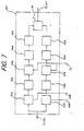
- Fig. 7 is a block diagram of detection and gate unit 401 in which echo signals reflected by fixed bodies or substances located along sound-beam B 1 are eliminated by a quadrature detection technique, and an echo signal reflected by flowing blood passing across sound-beam B 1 is gated over a relatively long range along sound-beam B 1 and sampled and held by a gated sample-and-holding technique.
- the long range corresponds to a sample volume SV 21 as shown in Fig. 6.
- a sample volume SV 22 along sound-beam B 2 can also have a long range.
- the ranges of sample volumes SV 21 and SV 22 can be extended respectively and accordingly the speed of blood can be measured even when the blood flows aslant with respect to sound-beams B 1 and B 2 as shown in Fig. 6.
- detection and gate unit 401 comprises two multipliers 41A and 41B, two low-pass filters 42A and 42B, two range gate circuits 43A and 43B, two high-pass filters 44A and 44B, and two square circuits 45A and 45B; and an adding circuit 46.
- range gate circuit 43A (43B) and high-pass filter 44A (44B) are for gated sample-and-holding, and others are for quadrature detection.
- an echo signal reflected by a fixed body or substance such as a blood vessel is given by and an echo signal reflected from flowing blood is given by
- Such sine and cosine signals are generated in sin-cos generator 403 in Fig. 5 and applied to detection and gate units 401 and 402 as shown in Fig. 5.
- the multiplications are effected by multipliers 41A and 41B respectively as shown in Fig. 7, and components of ⁇ and 2 ⁇ are removed by low-pass filters 42A and 42B.
- the output signals from low-pass filters 42A and 42B respectively become and
- the output signals E 1 (t) and E 2 (t) are fed to range gate circuits 43A and 43B respectively.
- Fig. 7 relates to echo signal C 1 (t) - see Fig. 5 - and hence to sound-beam B 1 and SV 21 ).
- Fig. 7 relates to echo signal C 1 (t) - see Fig. 5 - and hence to sound-beam B 1 and SV 21 ).
- the sampling time t s1 is determined by the distance between transducer 13 and the flowing blood, and sampling control signal V S for enabling sampling of echo signals at sampling time t s1 is provided by control unit 11 and fed to detection and gate units 401 and 402 respectively as shown in Figs. 5 and 7.
- the output signals of range gate circuits 43A and 43B are fed to high-pass filters 44A and 44B as shown in Fig. 7, and the first terms of formulae (6) and (7) are removed to leave only the second terms.
- output signals F 1 and F 2 of high-pass filters 44A and 44B become respectively and
- the output signals F 1 and F 2 are fed to square circuits 45A and 45B respectively and added in adding circuit 36; hence, the following square sum is obtained:
- the square sum G 1 (n) consists only of term B(t s1 +a n ), in other words, the required term B(t s1 +a n ), which is concerned only with the flowing blood, can be obtained.
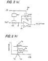
- Fig. 8(a) is a schematic circuit diagram of range gate circuit 43A, which functionally consists of two circuits: a gated sampling circuit comprising a gate pulse generator 431, a switching element 432, and a switching element 433; and a holding circuit comprising an operational amplifier 434, a resistor R, and a capacitor C.
- Range gate circuit 43A operates as follows when it receives sampling control signal V S from control unit 11. Just before sampling control signal V s is applied to range gate circuit 43A, switching elements 432 and 433 are OFF, so that an output voltage (S-H voltage) of range gate circuit 43A is a voltage charged on capacitor C.
- sampling control signal V S which is a pulse having a pulse width (period) ⁇ t s1 as shown in Fig. 8(b)
- range gate circuit 43A When sampling control signal V S , which is a pulse having a pulse width (period) ⁇ t s1 as shown in Fig. 8(b), is fed to range gate circuit 43A at time t s1 , switching element 432 is still OFF but switching element 433 becomes ON, so that the voltage charged on capacitor C is discharged; accordingly, the output of range gate circuit 43A achieves an initial potential.
- sampling control signal V s is ended at time t S2 as shown in Fig.
- switching element 433 becomes OFF, and at the same time, gate pulse generator 431 generates a gate pulse V G having a pulse width (time duration) ⁇ t s2 and gate pulse V G is applied to switching element 432 so that switching element 432 becomes ON during time duration ⁇ t s2 . Accordingly, mean value of the echo signals of sound-beam B 1 is held at time t s2 on capacitor C during time duration ⁇ t s2 . (A value determined by echo signals of sound-beam B 1 over the time duration ⁇ t s2 from an initial time t s2 is thus stored in capacitor C).
- Time duration ⁇ t s2 is a sampling time duration which corresponds to the range of sample volume SV21, and the voltage charged on capacitor C is the S-H voltage of range gate circuit 43A; the S-H voltage is fed to high-pass filter 44A as shown in Fig. 7.
- the echo signal C 2 (t) is processed by detection and gate unit 402 similarly to the processing of C1(t) by detection and gate unit 401, and a square sum G 2 (n) is obtained.
- Square sums G1 (n) and G 2 (n) are fed to time-difference detection circuit 24 in which a time difference between square sum G1(n) and square sum G 2 (n) is detected.
- the output of time-difference detection circuit 24 is fed to a speed calculating circuit 25 in which the speed of blood which flows through sample volumes SV 21 and SV 22 is calculated.
- the operations of time-difference detection circuit 24 and speed calculation circuit 25 in blood flowmeter 201 are similar to such operations provided in the previously proposed blood flowmeter 101.
- blood flowmeter 201 is able to measure speed in respect of blood which flows perpendicularly with respect to the sound-beams, or blood which flows aslant to the sound-beams.
- speed should be understood as "a component of speed (velocity) perpendicular to the sound-beam” to be exact, because when blood flows aslant to the sound-beam, the direction of the blood speed is also slant to the sound-beam; however, as seen in the above discussion, blood flowmeter 201 only measures "a component of speed perpendicular to the sound-beam".
- the quadrature detection and correlation detection technique applied to blood flowmeter 201 can be used for measuring speed of blood which flows along a sound-beam.
- two sample volumes are properly positioned "along" the single sound-beam; in this case the sample volumes need not be so long as used in blood flowmeter 201; the simple sample and hold technique can be used instead of the range gate circuit used in blood flowmeter 201, as is employed in the previously proposed flowmeter 101.
- true speed of blood which flows aslant with respect to a sound-beam can be obtained by calculating a vector sum of a horizontal speed component measured by blood flowmeter 201 and a vertical speed component measured using the quadrature detection and correlation detection technique, or measured by a Doppler type blood flowmeter.
Landscapes
- Engineering & Computer Science (AREA)
- Physics & Mathematics (AREA)
- Health & Medical Sciences (AREA)
- Remote Sensing (AREA)
- Life Sciences & Earth Sciences (AREA)
- Radar, Positioning & Navigation (AREA)
- Acoustics & Sound (AREA)
- Pathology (AREA)
- Public Health (AREA)
- Biomedical Technology (AREA)
- Heart & Thoracic Surgery (AREA)
- Medical Informatics (AREA)
- Molecular Biology (AREA)
- Surgery (AREA)
- Animal Behavior & Ethology (AREA)
- General Health & Medical Sciences (AREA)
- Radiology & Medical Imaging (AREA)
- Veterinary Medicine (AREA)
- Nuclear Medicine, Radiotherapy & Molecular Imaging (AREA)
- Biophysics (AREA)
- Hematology (AREA)
- Computer Networks & Wireless Communication (AREA)
- General Physics & Mathematics (AREA)
- Ultra Sonic Daignosis Equipment (AREA)
Abstract
Description
- The present invention relates to an ultrasound blood flowmeter of a correlation detection type.
- Usually, a Doppler effect type blood flowmeter is used in the measurement of blood flow speed. However, the speed measured by such a flowmeter is merely the component of blood flow velocity in the direction of a sound beam used in the measurement. In other words, speed (velocity component) perpendicular to the sound-beam cannot be measured by a Doppler effect type blood flowmeter. A correlation detection type blood flowmeter can measure the speed of a blood flow perpendicular to a measurement sound-beam. The correlation detection type blood flowmeter was invented by the inventor of the present invention and described in Japanese laid-open patent No. 58-71464 in 1983. Before discussing the present invention, that previously proposed correlation detection type blood flowmeter will be explained with reference to Fiqs. 1 and 2, to facilitate understanding of the present invention.
- Fig. 1 is a schematic diagram illustrating the relationship between sound-beams (B1 and B2) formed by the previously proposed correlation detection type blood flowmeter 101 (blood flowmeter 101) and a
blood flow human body 300. - The
blood flowmeter 101 comprises an ultrasound transducer (transducer) TD placed on asurface 303 of thebody 300; transducer TD forms dual sound-beams B1 and B2 for measuring the speed ofblood flow 301, which flows almost perpendicularly with respect to sound-beams B1 and B2; transducer TD sends pulsed or burst ultrasound waves (burst sound waves) intohuman body 300 along sound-beams B1 and B2 and receives echo signals arising from reflections of the sound-beams by substances located along sound-beams B1 and B 2. - SV11 and SV12 are called sample volumes and they relate to sound-beams B1 and B2 respectively. Sample volumes SV11 and SV12 are equally positioned (equally distant) from transducer TD. The location of the flowing blood is determined by other ultrasound imaging means, and the positions of sample volumes SV11 and SV12 are adjusted so that
blood flow 301 is caught by (lies within) those sample volumes SV11 and SV12. - Fig. 2 is a schematic block diagram of
blood flowmeter 101. In the Figure, 13 is an ultrasound transducer which corresponds to transducer TD in Fig. 1. Transducer 13 is a multi array type ultrasound transducer which consists of a plurality of transducer elements and operates rather like the familiar phased array antenna of a radar system. - Applying
transducer 13 toblood flowmeter 101,blood flowmeter 101 may operate in two modes: a scanning mode and a focusing mode. The former mode is used for providing ultrasound imagery, such as B-mode imagery, and the latter is used for measuring blood speed. A change from one mode to the other can be easily effected by electronic means. Fig. 2 relates to the focusing mode in which two focused sound-beams B1 and B2 are formed. Actually, a blood flowmeter operates in combination with a unit for providing the scanning mode, but that is omitted in Fig. 2. - A
control unit 11 generates timing and sampling control signals. The timing signal is for controllingtransducer 13 and aswitching circuit 14, and the sampling control signal is for controlling sample-and-hold (S-H)circuits control unit 11, adrive unit 12 outputs driving pulses for drivingtransducer 13 to send burst sound waves out from the transducer elements oftransducer 13; the generated driving pulses synchronize with the timing signals fromcontrol unit 11. - The
switching unit 14 is for switchingtransducer 13 so as to send the burst sound waves and to receive reflected sound waves under the control ofcontrol unit 11. When switchingunit 14 is turned to T (Fig. 2 shows this case) the transducer elements send the burst sound waves. After sending of the burst sound waves, switchingunit 14 is turned to R, and then the transducer elements receive the reflected sound waves and convert them into electric echo signals (echo signals) respectively. - Echo signals transduced by
transducer 13 are fed to amplifier elements of anamplifier 15 throughswitching unit 14 and fed to delay-line units 16 and 17. Delay-line units 16 and 17 correspond to sound-beams B1 and B2 respectively and each consists of delay-line elements which correspond to the transducer elements and compensate time differences of the received signals, so that the echo signals received along sound-beams B1 and B2 can be simply added byadders - The echo signals added by
adders S-H circuits amplifiers S-H circuits adders control unit 11, and held. Sampling time tsl is determined by observing the location of the flowing blood, and sampling control signal VS is produced by manual adjustment ofcontrol unit 11. The determination of sampling time ts1 is equivalent to the determination of the positions of sample volumes SV11 and SV 12. - Fig. 3 is a waveform diagram illustrating mutual time relationships between burst sound waves, added echo signals, sampling control signals, and S-H voltages.
- In Fig. 3, (a) is a train of burst sound waves, each of which bursts commences at a time t0, having a period T; (b) and (c) show added echo signals with respect to sound-beams B1 and B2; (d) shows a train of sampling control signals, each being generated at time ts1 counted from a corresponding time t0; and (e) and (f) show S-H voltages VSH1 and VSH2 which correspond to sample volumes SV 11 and SV12 respectively.
- The S-H voltages VSH1 and VSH2 are fed to a time-
difference detection circuit 24 which is for detecting a time difference between respective peak amplitudes of S-H voltages VSH1 and VSH2 by a cross correlation technique. - Fig. 4 illustrates a cross correlation relationship between peak amplitudes. As shown in Fig. 4, the amplitudes of S-H voltages VSH1 and VSH2 both have peaks. This is due to the fact that blood has a nature such that it flows in a state with small gathered-together masses of red blood corpuscles; the amplitude variation depends on the sizes of such masses. When blood flows almost perpendicularly with respect to sound-beams B1 and B2 passing through sample volumes SV11 and SV12, time-
difference detection circuit 24 picks up peak amplitudes P11 and P21 from S-H voltages VSH1 and VSH2 respectively and detects a time-difference voltage Vtd between individual peak amplitudes P11 (or P12, --, or P1n) and P21 (or P22, --, or P2n) producing an output voltage called a time-difference voltage Vtd. The time-difference direction circuit 24 comprises a fixed delay-line, a variable delay-line, and an automatic signal coincidence circuit; the details of which were given in Japanese laid-open patent No. 58-71464 in 1983. The time difference voltage Vtd is fed to aspeed calculating circuit 25 in which the speed of blood which flows almost perpendicularly with respect to sound-beams B1 and B2 passing through sample volumes SV11 and SV12 is calculated. The calculation is performed by dividing a distance between sample volumes SV 11 and SV12 by time difference ttd; the distance can be obtained in advance by determining the product of distance betweentransducer 13 and sample volume SV11 or SV12 and angle (radians) between sound-beams B1 and B2. - Thus, the correlation detection type blood flowmeter can measure the speed of blood which flows almost perpendicularly with respect to a measuring sound-beam. This is great advantage compared with the Doppler type blood flowmeter which can only measure the speed of blood flowing along a measuring sound-beam. However, in the previously proposed correlation detection type blood flowmeter, the sample volume SV11 or SV12 has almost no range to pick up the blood mass along the sound-beam, so that it has been very hard to detect the flowing blood, because it is hard to adjust sample volumes SV11 and SV12 so as to catch the flowing blood; there is often a case that the blood flows aslant to the sound-beam as shown by
blood flow 302 in Fig. 1. This has been a problem with the previously proposed correlation detection type blood flowmeter. Furthermore, signal reflections caused by a fixed substance or body such as a blood vessel disturb detection of echo signals reflected by flowing blood, and this has been another problem of the previously proposed correlation detection type blood flowmeter. - An embodiment of the present invention can afford an improvement in relation to a correlation detection type blood flowmeter so that the blood flowmeter can measure the speed of flowing blood which flows not only perpendicularly with respect to but also aslant with respect to a sound-beam provided by the blood flowmeter.
- An embodiment of the present invention can afford an improvement in relation to a blood flowmeter so that the blood flowmeter can be used to measure the speed of flowing blood with high accuracy and reliability by decreasing disturbances due to echo signals reflected by fixed bodies or substances located along the sound-beam.
- In an embodiment of the present invention a range gate circuit and a quadrature detection circuit are employed in the blood flowmeter; the former is for increasing the serviceable range of a sample volume along a sound-beam, and the latter is for decreasing the disturbances due to echo signals reflected by fixed bodies or substances.
- Reference is made, by way of example, to the accompanying drawings, in which:
- Fig. 1 is a schematic diagram illustrating interrelationships between sample volumes, provided by the previously proposed correlation detection type blood flowmeter, and a blood flow;
- Fig. 2 is a schematic block diagram of the previously proposed correlation detection type blood flowmeter;
- Fig. 3 is a waveform diagram for assistance in illustrating operations of the previously proposed correlation detection type blood flowmeter, in which Figure
- (a) is a waveform of burst sound waves,
- (b) is a waveform of an echo signal with respect to a sound-beam B1,
- (c) is a waveform of an echo signal with respect to a sound-beam B2,
- (d) is a waveform of a train of sampling control signals,
- (e) is a waveform of an S-H voltage with respect to sound-beam B1, and
- (f) is a waveform of an S-H voltage with respect to sound-beam B2;
- Fig. 4 is a waveform chart in a graphical form for illustrating a cross correlation between two S-H voltages;
- Fig. 5 is a schematic block diagram illustrating a correlation detection type blood flowmeter embodying the present invention;
- Fig. 6 is a schematic diagram illustrating interrelationships between sample volumes, provided by a correlation detection type blood flowmeter embodying the present invention, and a blood flow;
- Fig. 7 is a schematic block diagram of a detection and gate unit of a correlation detection type blood flowmeter embodying the present invention;
- Fig. 8(a) is a schematic circuit diagram of a range gate circuit of a detection and gate unit of a correlation detection type blood flowmeter embodying the present invention; and
- Fig 8(b) is a waveform chart in graphical form, illustrating operations of a range gate circuit of a correlation detection type blood flowmeter embodying the present invention.
- In Fig. 5, which illustrates a correlation detection type blood flowmeter 201 (blood flowmeter 201) embodying the present invention, each block with the same reference sign as a block in Fig. 2 has the same or similar function to the block of Fig. 2. The
blood flowmeter 201 comprises two quadrature-detection and range-gate units (detection and gate units) 401 and 402 and a sine-cosine signal generator (sin-cos generator) 403. The detection andgate units cosine generator 403 are for providing improvement in relation toS-H circuits blood flowmeter 101 shown in Fig. 2. The detection andgate units - Fig. 7 is a block diagram of detection and
gate unit 401 in which echo signals reflected by fixed bodies or substances located along sound-beam B1 are eliminated by a quadrature detection technique, and an echo signal reflected by flowing blood passing across sound-beam B1 is gated over a relatively long range along sound-beam B1 and sampled and held by a gated sample-and-holding technique. The long range corresponds to a sample volume SV21 as shown in Fig. 6. Similarly, as seen in Fig. 6, a sample volume SV22 along sound-beam B2 can also have a long range. Thus, the ranges of sample volumes SV21 and SV22 can be extended respectively and accordingly the speed of blood can be measured even when the blood flows aslant with respect to sound-beams B1 and B2 as shown in Fig. 6. - In Fig. 7, detection and
gate unit 401 comprises twomultipliers pass filters range gate circuits pass filters square circuits circuit 46. In the above circuits,range gate circuit 43A (43B) and high-pass filter 44A (44B) are for gated sample-and-holding, and others are for quadrature detection. - When burst ultrasound waves are sent into a body, an echo signal reflected by a fixed body or substance such as a blood vessel is given by

- B(t+an)·sin(ωt+bn), where,
- t: time,
- A: amplitude function of an echo signal reflected by a fixed body or substance,
- B: amplitude function of an echo signal reflected by flowing blood,
- ω: angular velocity of ultrasound transmitted in the body,
- a: a factor concerning the Doppler effect,
- b: a factor concerning flowing blood velocity,
- n: respective number of sequential driving pulses, and
- 0: a phase difference concerned with ultrasound as reflected by the fixed body or substance.
- When echo signals presented by formulas (1) and (2) are superimposed (actual echo signals being superimposed) the following echo signal C(t) is obtained by adding formulas (1) and (2):

- In formula (3), a necessary term for measuring the blood speed is a term B(t + a). However, as seen in formula (3) it is impossible to detect the term B(t + a ) simply from formula. (3).
- This can be solved by applying a quadrature detection technique as follows.
- Firstly, multiply a sine signal and a cosine signal with echo signal C(t) so that following signals D1(t) and D2(t) are obtained:


- Such sine and cosine signals are generated in sin-
cos generator 403 in Fig. 5 and applied to detection andgate units multipliers pass filters pass filters 

- Secondarily, the output signals E1(t) and E2(t) are fed to range
gate circuits range gate circuits transducer 13 and the flowing blood, and sampling control signal VS for enabling sampling of echo signals at sampling time ts1 is provided bycontrol unit 11 and fed to detection andgate units range gate circuits pass filters pass filters 

- The output signals F1 and F2 are fed to
square circuits 
- The square sum G1(n) consists only of term B(ts1+an), in other words, the required term B(ts1+an), which is concerned only with the flowing blood, can be obtained.
- Fig. 8(a) is a schematic circuit diagram of
range gate circuit 43A, which functionally consists of two circuits: a gated sampling circuit comprising agate pulse generator 431, aswitching element 432, and aswitching element 433; and a holding circuit comprising anoperational amplifier 434, a resistor R, and a capacitor C.Range gate circuit 43A operates as follows when it receives sampling control signal VS fromcontrol unit 11. Just before sampling control signal Vs is applied to rangegate circuit 43A, switchingelements range gate circuit 43A is a voltage charged on capacitor C. When sampling control signal VS, which is a pulse having a pulse width (period)Δts1 as shown in Fig. 8(b), is fed to rangegate circuit 43A at time ts1, switchingelement 432 is still OFF but switchingelement 433 becomes ON, so that the voltage charged on capacitor C is discharged; accordingly, the output ofrange gate circuit 43A achieves an initial potential. When sampling control signal Vs is ended at time tS2 as shown in Fig. 8(b), switchingelement 433 becomes OFF, and at the same time,gate pulse generator 431 generates a gate pulse VG having a pulse width (time duration) Δts2 and gate pulse VG is applied to switchingelement 432 so that switchingelement 432 becomes ON during time duration Δts2. Accordingly, mean value of the echo signals of sound-beam B1 is held at time ts2 on capacitor C during time duration Δts2. (A value determined by echo signals of sound-beam B1 over the time duration Δts2 from an initial time ts2 is thus stored in capacitor C). Time duration Δts2 is a sampling time duration which corresponds to the range of sample volume SV21, and the voltage charged on capacitor C is the S-H voltage ofrange gate circuit 43A; the S-H voltage is fed to high-pass filter 44A as shown in Fig. 7. - The echo signal C2(t) is processed by detection and
gate unit 402 similarly to the processing of C1(t) by detection andgate unit 401, and a square sum G2(n) is obtained. Square sums G1 (n) and G2(n) are fed to time-difference detection circuit 24 in which a time difference between square sum G1(n) and square sum G2(n) is detected. The output of time-difference detection circuit 24 is fed to aspeed calculating circuit 25 in which the speed of blood which flows through sample volumes SV21 and SV22 is calculated. The operations of time-difference detection circuit 24 andspeed calculation circuit 25 inblood flowmeter 201 are similar to such operations provided in the previously proposedblood flowmeter 101. - As will be clear from the above discussion,
blood flowmeter 201 is able to measure speed in respect of blood which flows perpendicularly with respect to the sound-beams, or blood which flows aslant to the sound-beams. However, in this connection the word "speed" should be understood as "a component of speed (velocity) perpendicular to the sound-beam" to be exact, because when blood flows aslant to the sound-beam, the direction of the blood speed is also slant to the sound-beam; however, as seen in the above discussion,blood flowmeter 201 only measures "a component of speed perpendicular to the sound-beam". - The quadrature detection and correlation detection technique applied to
blood flowmeter 201 can be used for measuring speed of blood which flows along a sound-beam. In this case, two sample volumes are properly positioned "along" the single sound-beam; in this case the sample volumes need not be so long as used inblood flowmeter 201; the simple sample and hold technique can be used instead of the range gate circuit used inblood flowmeter 201, as is employed in the previously proposedflowmeter 101. - Accordingly, true speed of blood which flows aslant with respect to a sound-beam can be obtained by calculating a vector sum of a horizontal speed component measured by
blood flowmeter 201 and a vertical speed component measured using the quadrature detection and correlation detection technique, or measured by a Doppler type blood flowmeter.
Claims (3)
Applications Claiming Priority (2)
| Application Number | Priority Date | Filing Date | Title |
|---|---|---|---|
| JP210800/84 | 1984-10-08 | ||
| JP59210800A JPS61100236A (en) | 1984-10-08 | 1984-10-08 | Correlation detection type ultrasonic blood stream meter |
Publications (3)
| Publication Number | Publication Date |
|---|---|
| EP0177942A2 true EP0177942A2 (en) | 1986-04-16 |
| EP0177942A3 EP0177942A3 (en) | 1988-07-27 |
| EP0177942B1 EP0177942B1 (en) | 1992-04-01 |
Family
ID=16595340
Family Applications (1)
| Application Number | Title | Priority Date | Filing Date |
|---|---|---|---|
| EP85112767A Expired EP0177942B1 (en) | 1984-10-08 | 1985-10-08 | Correlation detection type ultrasound blood flowmeter |
Country Status (4)
| Country | Link |
|---|---|
| US (1) | US4693319A (en) |
| EP (1) | EP0177942B1 (en) |
| JP (1) | JPS61100236A (en) |
| DE (1) | DE3585766D1 (en) |
Cited By (3)
| Publication number | Priority date | Publication date | Assignee | Title |
|---|---|---|---|---|
| EP0226044A2 (en) * | 1985-11-14 | 1987-06-24 | Fujitsu Limited | Display of a stream line of an inhomogeneous flowing medium |
| EP0361610A1 (en) * | 1988-09-30 | 1990-04-04 | Laboratoires D'electronique Philips | Echographic apparatus for measuring the transversal speed of moving organs and the blood flow |
| EP2637037A1 (en) * | 2012-03-08 | 2013-09-11 | Samsung Medison Co., Ltd. | Method and apparatus for obtaining movement velocity and direction of tissue |
Families Citing this family (17)
| Publication number | Priority date | Publication date | Assignee | Title |
|---|---|---|---|---|
| DE3689698T2 (en) * | 1985-05-20 | 1994-07-21 | Matsushita Electric Ind Co Ltd | Blood speed meter based on the ultrasound Doppler principle. |
| JP2556701B2 (en) * | 1987-05-18 | 1996-11-20 | グラム株式会社 | Ultrafiltration amount and dialysate concentration measuring device |
| US4979513A (en) * | 1987-10-14 | 1990-12-25 | Matsushita Electric Industrial Co., Ltd. | Ultrasonic diagnostic apparatus |
| US5103181A (en) * | 1988-10-05 | 1992-04-07 | Den Norske Oljeselskap A. S. | Composition monitor and monitoring process using impedance measurements |
| US5109857A (en) * | 1991-03-04 | 1992-05-05 | Duke University | Ultrasound time domain velocity detection method and apparatus |
| JPH04307040A (en) * | 1991-04-05 | 1992-10-29 | Yokogawa Medical Syst Ltd | Mutual correlation flow mapping apparatus for doppler |
| US5357964A (en) * | 1993-02-08 | 1994-10-25 | Spivey Brett A | Doppler imaging device |
| JP3462584B2 (en) * | 1994-02-14 | 2003-11-05 | フクダ電子株式会社 | Ultrasound diagnostic equipment |
| DE69710725T2 (en) * | 1996-07-02 | 2002-11-21 | B K Medical As Gentofte | DEVICE FOR DETERMINING MOVEMENTS AND SPEEDS OF MOVING OBJECTS |
| US6725076B1 (en) * | 1999-05-10 | 2004-04-20 | B-K Medical A/S | Vector velocity estimation using directional beam forming and cross correlation |
| US6685645B1 (en) * | 2001-10-20 | 2004-02-03 | Zonare Medical Systems, Inc. | Broad-beam imaging |
| US20020173721A1 (en) * | 1999-08-20 | 2002-11-21 | Novasonics, Inc. | User interface for handheld imaging devices |
| US7833163B2 (en) * | 2003-12-10 | 2010-11-16 | Siemens Medical Solutions Usa, Inc. | Steering angle varied pattern for ultrasound imaging with a two-dimensional array |
| US7105981B2 (en) * | 2003-12-10 | 2006-09-12 | Siemens Medical Solutions Usa, Inc. | Medical imaging transmit spectral control using aperture functions |
| US9494454B2 (en) * | 2013-12-06 | 2016-11-15 | Joseph Baumoel | Phase controlled variable angle ultrasonic flow meter |
| US9752907B2 (en) | 2015-04-14 | 2017-09-05 | Joseph Baumoel | Phase controlled variable angle ultrasonic flow meter |
| US10256538B2 (en) * | 2015-08-25 | 2019-04-09 | The Boeing Company | Integrated true time delay for broad bandwidth time control systems and methods |
Citations (6)
| Publication number | Priority date | Publication date | Assignee | Title |
|---|---|---|---|---|
| DE1798104B2 (en) * | 1968-08-22 | 1973-04-12 | Siemens AG, 1000 Berlin u. 8000 München | DEVICE FOR MEASURING THE SPEED OF MEDIA FLOWING IN LINES |
| US3762221A (en) * | 1970-07-06 | 1973-10-02 | J Coulthard | Measurement of fluid flow rates |
| US4217909A (en) * | 1978-08-23 | 1980-08-19 | General Electric Company | Directional detection of blood velocities in an ultrasound system |
| US4324258A (en) * | 1980-06-24 | 1982-04-13 | Werner Huebscher | Ultrasonic doppler flowmeters |
| US4334543A (en) * | 1978-12-04 | 1982-06-15 | Hoffmann-La Roche Inc. | Method and apparatus for flow velocity determination |
| US4417584A (en) * | 1981-05-25 | 1983-11-29 | Institut National De La Sante Et De La Recherche Medicale | Real-time measuring method and apparatus displaying flow velocities in a segment of vessel |
Family Cites Families (6)
| Publication number | Priority date | Publication date | Assignee | Title |
|---|---|---|---|---|
| US3334622A (en) * | 1964-12-15 | 1967-08-08 | Branson Instr | Method and apparatus for electroacoustic exploration |
| US4181134A (en) * | 1977-09-21 | 1980-01-01 | Mason Richard C | Cardiotachometer |
| US4265126A (en) * | 1979-06-15 | 1981-05-05 | General Electric Company | Measurement of true blood velocity by an ultrasound system |
| FI67627C (en) * | 1981-10-19 | 1985-04-10 | Eino Haerkoenen | PROCEDURE FOR THE ORGANIZATION OF THE PROCESSING OF STRUCTURES AND THE EXTENSION OF GENERATION OF THE GENOM UTNYTTJANDET AV ULTRALJUD |
| JPS58188433A (en) * | 1982-04-28 | 1983-11-02 | アロカ株式会社 | Ultrasonic diagnostic apparatus |
| NL8202079A (en) * | 1982-05-19 | 1983-12-16 | Ihc Holland Nv | METHOD AND METHOD FOR MEASURING THE FLOW RATE OF A MEDIUM |
-
1984
- 1984-10-08 JP JP59210800A patent/JPS61100236A/en active Granted
-
1985
- 1985-10-02 US US06/782,921 patent/US4693319A/en not_active Expired - Lifetime
- 1985-10-08 DE DE8585112767T patent/DE3585766D1/en not_active Expired - Fee Related
- 1985-10-08 EP EP85112767A patent/EP0177942B1/en not_active Expired
Patent Citations (6)
| Publication number | Priority date | Publication date | Assignee | Title |
|---|---|---|---|---|
| DE1798104B2 (en) * | 1968-08-22 | 1973-04-12 | Siemens AG, 1000 Berlin u. 8000 München | DEVICE FOR MEASURING THE SPEED OF MEDIA FLOWING IN LINES |
| US3762221A (en) * | 1970-07-06 | 1973-10-02 | J Coulthard | Measurement of fluid flow rates |
| US4217909A (en) * | 1978-08-23 | 1980-08-19 | General Electric Company | Directional detection of blood velocities in an ultrasound system |
| US4334543A (en) * | 1978-12-04 | 1982-06-15 | Hoffmann-La Roche Inc. | Method and apparatus for flow velocity determination |
| US4324258A (en) * | 1980-06-24 | 1982-04-13 | Werner Huebscher | Ultrasonic doppler flowmeters |
| US4417584A (en) * | 1981-05-25 | 1983-11-29 | Institut National De La Sante Et De La Recherche Medicale | Real-time measuring method and apparatus displaying flow velocities in a segment of vessel |
Cited By (5)
| Publication number | Priority date | Publication date | Assignee | Title |
|---|---|---|---|---|
| EP0226044A2 (en) * | 1985-11-14 | 1987-06-24 | Fujitsu Limited | Display of a stream line of an inhomogeneous flowing medium |
| EP0226044A3 (en) * | 1985-11-14 | 1989-06-07 | Fujitsu Limited | Display of a stream line of an inhomogeneous flowing medium |
| EP0361610A1 (en) * | 1988-09-30 | 1990-04-04 | Laboratoires D'electronique Philips | Echographic apparatus for measuring the transversal speed of moving organs and the blood flow |
| FR2637378A1 (en) * | 1988-09-30 | 1990-04-06 | Labo Electronique Physique | DEVICE FOR MEASUREMENT BY ECHOGRAPHY OF THE TRANSVERSE SPEED OF MOVING ORGANS AND BLOOD FLOWS |
| EP2637037A1 (en) * | 2012-03-08 | 2013-09-11 | Samsung Medison Co., Ltd. | Method and apparatus for obtaining movement velocity and direction of tissue |
Also Published As
| Publication number | Publication date |
|---|---|
| US4693319A (en) | 1987-09-15 |
| JPH0318458B2 (en) | 1991-03-12 |
| DE3585766D1 (en) | 1992-05-07 |
| EP0177942B1 (en) | 1992-04-01 |
| EP0177942A3 (en) | 1988-07-27 |
| JPS61100236A (en) | 1986-05-19 |
Similar Documents
| Publication | Publication Date | Title |
|---|---|---|
| EP0177942A2 (en) | Correlation detection type ultrasound blood flowmeter | |
| EP0014793B2 (en) | Ultrasound system and method for directional detection of blood velocities | |
| US5388461A (en) | Beamforming time delay correction for a multi-element array ultrasonic scanner using beamsum-channel correlation | |
| US5398216A (en) | Method for detecting two-dimensional flow for ultrasound color flow imaging | |
| EP0853768B1 (en) | Apparatus for and method of determining positional information for an object | |
| US4848356A (en) | Ultrasonic doppler blood flowmeter | |
| US5177691A (en) | Measuring velocity of a target by Doppler shift, using improvements in calculating discrete Fourier transform | |
| EP0535962B1 (en) | Ultrasonic diagnosing apparatus | |
| US4054862A (en) | Ranging system with resolution of correlator ambiguities | |
| EP0228070A2 (en) | Ultrasonic doppler diagnostic apparatus | |
| US3750152A (en) | Pulse-echo phase discriminator using deltic processing | |
| EP0312059A1 (en) | Ultrasonic diagnostic apparatus | |
| EP0212527A1 (en) | Pulsed doppler flow mapping apparatus | |
| US4884448A (en) | Ultrasonic doppler meter | |
| US5602343A (en) | Method of, and apparatus for, measuring the velocity of a fluid | |
| US5000184A (en) | Directional component measurement by echography | |
| US5383462A (en) | Wideband time-domain cross-correlation method using baseband data | |
| EP0807825B1 (en) | Ultrasonic continuous wave doppler blood flow-meter | |
| US5414675A (en) | Sonar system for detection of near bottom targets | |
| EP0474867B1 (en) | Method of processing doppler signal | |
| EP0173243B1 (en) | Apparatus for measuring the velocity of a stream of particles | |
| EP0794411A2 (en) | Flow measurement | |
| SU734591A1 (en) | Sea wave parameter measuring device | |
| Namas et al. | A feasible and accurate technique for determining the time-of-flight in ultrasonic distance measurements | |
| SU1661573A1 (en) | Acoustic hydrostatic level |
Legal Events
| Date | Code | Title | Description |
|---|---|---|---|
| PUAI | Public reference made under article 153(3) epc to a published international application that has entered the european phase |
Free format text: ORIGINAL CODE: 0009012 |
|
| AK | Designated contracting states |
Kind code of ref document: A2 Designated state(s): DE FR GB NL SE |
|
| PUAL | Search report despatched |
Free format text: ORIGINAL CODE: 0009013 |
|
| AK | Designated contracting states |
Kind code of ref document: A3 Designated state(s): DE FR GB NL SE |
|
| 17P | Request for examination filed |
Effective date: 19881007 |
|
| 17Q | First examination report despatched |
Effective date: 19910208 |
|
| GRAA | (expected) grant |
Free format text: ORIGINAL CODE: 0009210 |
|
| AK | Designated contracting states |
Kind code of ref document: B1 Designated state(s): DE FR GB NL SE |
|
| REF | Corresponds to: |
Ref document number: 3585766 Country of ref document: DE Date of ref document: 19920507 |
|
| ET | Fr: translation filed | ||
| PLBE | No opposition filed within time limit |
Free format text: ORIGINAL CODE: 0009261 |
|
| STAA | Information on the status of an ep patent application or granted ep patent |
Free format text: STATUS: NO OPPOSITION FILED WITHIN TIME LIMIT |
|
| 26N | No opposition filed | ||
| PGFP | Annual fee paid to national office [announced via postgrant information from national office to epo] |
Ref country code: GB Payment date: 19940929 Year of fee payment: 10 |
|
| PGFP | Annual fee paid to national office [announced via postgrant information from national office to epo] |
Ref country code: DE Payment date: 19941010 Year of fee payment: 10 |
|
| PGFP | Annual fee paid to national office [announced via postgrant information from national office to epo] |
Ref country code: FR Payment date: 19941011 Year of fee payment: 10 |
|
| PGFP | Annual fee paid to national office [announced via postgrant information from national office to epo] |
Ref country code: SE Payment date: 19941017 Year of fee payment: 10 |
|
| PGFP | Annual fee paid to national office [announced via postgrant information from national office to epo] |
Ref country code: NL Payment date: 19941031 Year of fee payment: 10 |
|
| EAL | Se: european patent in force in sweden |
Ref document number: 85112767.0 |
|
| PG25 | Lapsed in a contracting state [announced via postgrant information from national office to epo] |
Ref country code: GB Effective date: 19951008 |
|
| PG25 | Lapsed in a contracting state [announced via postgrant information from national office to epo] |
Ref country code: SE Effective date: 19951009 |
|
| PG25 | Lapsed in a contracting state [announced via postgrant information from national office to epo] |
Ref country code: NL Effective date: 19960501 |
|
| GBPC | Gb: european patent ceased through non-payment of renewal fee |
Effective date: 19951008 |
|
| PG25 | Lapsed in a contracting state [announced via postgrant information from national office to epo] |
Ref country code: FR Effective date: 19960628 |
|
| EUG | Se: european patent has lapsed |
Ref document number: 85112767.0 |
|
| PG25 | Lapsed in a contracting state [announced via postgrant information from national office to epo] |
Ref country code: DE Effective date: 19960702 |
|
| NLV4 | Nl: lapsed or anulled due to non-payment of the annual fee |
Effective date: 19960501 |
|
| REG | Reference to a national code |
Ref country code: FR Ref legal event code: ST |