EP0177250A2 - Implantable insulin administration device - Google Patents
Implantable insulin administration device Download PDFInfo
- Publication number
- EP0177250A2 EP0177250A2 EP85306786A EP85306786A EP0177250A2 EP 0177250 A2 EP0177250 A2 EP 0177250A2 EP 85306786 A EP85306786 A EP 85306786A EP 85306786 A EP85306786 A EP 85306786A EP 0177250 A2 EP0177250 A2 EP 0177250A2
- Authority
- EP
- European Patent Office
- Prior art keywords
- container
- pump
- check valve
- passageway
- housing
- Prior art date
- Legal status (The legal status is an assumption and is not a legal conclusion. Google has not performed a legal analysis and makes no representation as to the accuracy of the status listed.)
- Withdrawn
Links
Images
Classifications
-
- A—HUMAN NECESSITIES
- A61—MEDICAL OR VETERINARY SCIENCE; HYGIENE
- A61M—DEVICES FOR INTRODUCING MEDIA INTO, OR ONTO, THE BODY; DEVICES FOR TRANSDUCING BODY MEDIA OR FOR TAKING MEDIA FROM THE BODY; DEVICES FOR PRODUCING OR ENDING SLEEP OR STUPOR
- A61M5/00—Devices for bringing media into the body in a subcutaneous, intra-vascular or intramuscular way; Accessories therefor, e.g. filling or cleaning devices, arm-rests
- A61M5/14—Infusion devices, e.g. infusing by gravity; Blood infusion; Accessories therefor
- A61M5/142—Pressure infusion, e.g. using pumps
- A61M5/14244—Pressure infusion, e.g. using pumps adapted to be carried by the patient, e.g. portable on the body
- A61M5/14276—Pressure infusion, e.g. using pumps adapted to be carried by the patient, e.g. portable on the body specially adapted for implantation
- A61M5/1428—Pressure infusion, e.g. using pumps adapted to be carried by the patient, e.g. portable on the body specially adapted for implantation with manual pumping action
-
- A—HUMAN NECESSITIES
- A61—MEDICAL OR VETERINARY SCIENCE; HYGIENE
- A61M—DEVICES FOR INTRODUCING MEDIA INTO, OR ONTO, THE BODY; DEVICES FOR TRANSDUCING BODY MEDIA OR FOR TAKING MEDIA FROM THE BODY; DEVICES FOR PRODUCING OR ENDING SLEEP OR STUPOR
- A61M5/00—Devices for bringing media into the body in a subcutaneous, intra-vascular or intramuscular way; Accessories therefor, e.g. filling or cleaning devices, arm-rests
- A61M5/14—Infusion devices, e.g. infusing by gravity; Blood infusion; Accessories therefor
- A61M5/142—Pressure infusion, e.g. using pumps
- A61M5/14244—Pressure infusion, e.g. using pumps adapted to be carried by the patient, e.g. portable on the body
- A61M5/14276—Pressure infusion, e.g. using pumps adapted to be carried by the patient, e.g. portable on the body specially adapted for implantation
-
- A—HUMAN NECESSITIES
- A61—MEDICAL OR VETERINARY SCIENCE; HYGIENE
- A61M—DEVICES FOR INTRODUCING MEDIA INTO, OR ONTO, THE BODY; DEVICES FOR TRANSDUCING BODY MEDIA OR FOR TAKING MEDIA FROM THE BODY; DEVICES FOR PRODUCING OR ENDING SLEEP OR STUPOR
- A61M2209/00—Ancillary equipment
- A61M2209/04—Tools for specific apparatus
- A61M2209/045—Tools for specific apparatus for filling, e.g. for filling reservoirs
Definitions
- This invention relates to an implantable device for administering a measured amount of liquid, for example, insulin.
- One embodiment of the implantable device for administering a measured amount of liquid drug of the present invention might include a container of flexible material for storing the liquid drug. There is also provided means for percutaneously filling the container.
- the device further includes a pump having a resiliently compressible receptacle.
- a first check valve is connected between the container and the receptacle and allows flow only from the container toward the receptacle.
- a second check valve is connected to the receptacle and leads away from the receptacle for discharge in the body. The second check valve allows flow only from said receptacle for discharge in the body.
- Objects of the invention are to provide a device which permits freedom from multiple daily injections of insulin.
- Another object of the invention is to eliminate the use of electrical or electronic components within the body.
- Still another object of the invention is to provide a low cost simple design which does not have moving parts and operates reliably.
- Related objects of the invention are to provide a device which permits control of the amount of insulin administered by a properly instructed patient and to provide a device in which the insulin solution needs to be replenished at only long time periods, such as only once a week.
- an implantable device for administering a measured amount of insulin.
- the entire device 10 is implanted subcutaneously and permits the patient to administer a measured amount of insulin by depressing the pump 11.
- the pump 11 is positioned over the sternum 9 of the patient.
- the device further includes an access port or means 12 for percutaneously filling the container.
- the access port 12 can be used on perhaps a once a week basis to inject a substantial portion of insulin into the sack or container 16.
- the sack or container 16 is connected to the access port 12 by a flexible tubing section 17.
- the access port 12 includes a needle stop disc 20 and also a housing 21 as well as a grid 22.
- the access port 12 includes a silastic housing 25 which is compressed within the stainless steel housing 21.
- the grid 22 is then mounted on the metal housing 21 so as to retain the silastic 25 within the housing and to hold it in a compressed condition so that when the needle 26 is inserted through the grid the silastic yields to permit passage of the needle yet when the needle is withdrawn the silastic comes together and closes off the needle produced puncture. It can be seen from FIG.
- FIG. 3 also illustrates that the tubing 17 couples the hollow interior 27 of the access port 12 to the upper end 30 of the sack 16.
- the tubing 17 is attached to the silastic housing 25 and the sack 16 by suitable adhesive.
- the access port 12 When the insulin administrating device of the invention is implanted in the body, the access port 12 is located in the left lower quadrant of the abdomen.
- the sack 16 is implanted in the properitoneal fat so that it is subjected to peritoneal pressure.
- the tubing 17 from the access port opens in the upper part of the sack 16 while the outlet tubing 31 has its inlet end 32 in the center of the lower part of the sack 16.
- the tubing 31 is so arranged because the device is normally operated when the patient is in the erect or semi-erect position so that gravity will tend to pull the liquid toward the lower end of the sack 16.
- the flexible tubing 31 leads into an auxiliary pump 35.
- the auxiliary pump 35 has a pair of cup shaped members 36 and 37 joined together at their outer peripheries. Each of the cup shaped members has a concave side 40 and a convex side 41.
- the construction of the pump 11 is generally the same as the construction of the pump 35.
- the pump 11 forms the primary pumping means for the device while the pump 35 forms an auxiliary pumping means.
- the pump 11 differs in construction from the pump 35 in that the flexible tubing sections 42 and 45 leading into and out of the pump 11 are secured to the sides of the pump 11 to generally retain the configuration and arrangement of the parts when the insulin administering device is implanted in the body.
- a further section 46 of tubing leads from the auxiliary pump 35 into the check valve 47.
- Still another check valve 50 is provided and is connected to the section of tubing 45 and also to a further section of tubing 51.
- the section of tubing 51 is closed at its end 52 and has a series of openings 55 in its wall at its distal end.
- the openings 55 are arranged to be positioned within the peritoneum so that the discharge location of the insulin is in the peritoneum.
- the check valves 47 and 50 are arranged so as to only permit flow of fluid in the direction of the arrows 56 and 57.
- the detail of construction of a representative one of the check valves 47 is shown in FIG. 4.
- the tube 46 has an external cylindrical surface 60 and a closed end 61.
- the tube 46 also has a passageway 62 which opens through the external cylindrical surface 60.
- a housing 65 surrounds the closed end and the passageway. The housing 65 is closed except for the discharge passageway 66 which connects to the section 42 of tubing.
- a short length 67 of flexible stretchable expandable tubular material is fixed to the tube 46 and covers the passageway 62. The length of material 67 is adapted to stretch and expand to permit flow of fluid to occur from the tube through the passageway 62 into the housing and out the discharge passageway 66.
- the flexible member on the other hand also is adapted to contract around the tube 46 and the passageway 62 to block flow from the housing into the passageway and tube when the pressure in the housing is greater than the pressure in the first passageway. As suggested in FIG.
- the fingers of the patient are used to compress the pump 11 and the pump 35 by pressing against the skin 68.
- Pump 11 is the primary pumping means of the device. As long as the pump 11 is used at every meal, it will function reliably. It is possible that after being left idle for several days, the inlet valve 47 may stick and fail to function. For this reason the auxiliary pump 35 has been provided and may be used to force the inlet valve 47 open if the proximal tubing 31 is compressed to avoid a backward motion of the fluid.
- the patient's finger 72 is shown in position compressing the tubing 31 to prevent such backward motion.
- the finger 71 is shown in position to squeeze the pump 35 while the finger 72 compresses the tubing 31.
- the pump 35 is only a failsafe device and normally will not be needed to be used.
- the patient will compress the pump 11 by pressing the pump against the sternum 9 as suggested for the finger 70. This will cause the fluid within the pump to be expelled through the tubing section 45 and the check valve 50. Then when the pressure is released upon the pump causing the two cup shaped sides of the pump to move apart further fluid will flow into the pump through the check valve 47.
- the upper end 30 of the sack and also the lower end 80 are made from cellular plastic material so as to give the upper and lower ends of the sack a relatively rigid construction. Also, two suture holes 81 are located at the upper end 30 and the lower end 80 of the sack for securing the sack in place.
- tubing 31 is connected to sack 16 and pump 35 by appropriate adhesive as is tubing 46 to check valve 47 and pump 35, as well as tubing 42 to pump 11 and check valve 47, as well as tubing 45 to pump 11 and check valve 50 and tubing 51 to check valve 50.
- the insulin administering device of the present invention does provide freedom from multiple daily injections of insulin. It has been found that such a device need only be filled approximately once a week in order to provide sufficient insulin. The concentration of the insulin solution can be adjusted so that only a few pressures on the subcutaneous pump delivers the precise needed amount of protection at meal time.
- the present invention provides a reliable mechanical operation which does not involve electrical or electronic components.
- the present device is of simple construction and low cost and permits accurate control of the amount of insulin administered by a properly instructed patient. It should be mentioned that during one week a small amount of evaporation will occur in the system. It is therefore suggested that the water vapor probably in amount of 3-6 cc be aspirated along with any remaining old insulin before the weekly replenishment is accomplished.
Abstract
Description
- This invention relates to an implantable device for administering a measured amount of liquid, for example, insulin.
- Various types of devices are known for administering drugs to a patient. In certain situations it is necessary that drugs be administered parenterally on a repeated continuous basis as often as a number of times a day. For example, diabetes may require injections of insulin on the order of twice a day. Such injections are irritating to the skin and tend to cause infection particularly when they must be accomplished so often. There are in existence the following United States patents which may disclose prior art; 3,756,243 issued to Shults; 3,827,439 issued to Shults; 3,951,147 issued to Tucker; 4,013,074 issued to Siposs; 4,191,181 issued to Franetski; 4,261,341 issued to Hakim, 4,265,241 issued to Portner; 4,298,002 issued to Ronel; 4,360,019 issued to Portner and 4,373,527 issued to Fischell. Still another reference of interest is the publication Medical Progress Through Technology 680 - Vol. 5 No. 4 (1978-05). The known devices suffer from a number of disadvantages. They are expansive and complicated in design. They require multiple daily injections. They are electric or electronic in nature. They involve moving parts.
- One embodiment of the implantable device for administering a measured amount of liquid drug of the present invention might include a container of flexible material for storing the liquid drug. There is also provided means for percutaneously filling the container. The device further includes a pump having a resiliently compressible receptacle. A first check valve is connected between the container and the receptacle and allows flow only from the container toward the receptacle. A second check valve is connected to the receptacle and leads away from the receptacle for discharge in the body. The second check valve allows flow only from said receptacle for discharge in the body.
- Objects of the invention are to provide a device which permits freedom from multiple daily injections of insulin.
- Another object of the invention is to eliminate the use of electrical or electronic components within the body.
- Still another object of the invention is to provide a low cost simple design which does not have moving parts and operates reliably.
- Related objects of the invention are to provide a device which permits control of the amount of insulin administered by a properly instructed patient and to provide a device in which the insulin solution needs to be replenished at only long time periods, such as only once a week.
- The invention disclosed here will be understood better with reference to the following drawing in which:
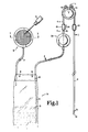
- FIG. 1 is a front elevational view of the insulin administrating device of the present invention.
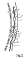
- FIG. 2 is a section taken along the line 2-2 of FIG. 1 along the lumen of the device of FIG. 1. and showing how the device is implanted in the body of the patient and how the device is manipulated by the fingers of the patient.
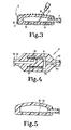
- FIG. 3 is an enlarged section taken along the line 3-3 of FIG. 1 in the direction of the arrows.
- FIG. 4 is an enlarged section taken along the line 4-4 of FIG. 1 in the direction of the arrows.
- FIG. 5 is a view similar to FIG. 3 but showing the structure of FIG. 3 in an intermediate manufacturing step.
- For the purposes of promoting an understanding of the principles of the invention, reference will now be made to the embodiment illustrated in the drawings and specific language will be used to describe the same. It will nevertheless be understood that no limitation of the scope of the invention is thereby intended, such alterations and further modifications in the illustrated device, and such further applications of the principles of the invention as illustrated therein being contemplated as would normally occur to one skilled in the art to which the invention relates.
- Referring more particularly to the drawing, there is illustrated an implantable device for administering a measured amount of insulin. The
entire device 10 is implanted subcutaneously and permits the patient to administer a measured amount of insulin by depressing the pump 11. The pump 11 is positioned over thesternum 9 of the patient. The device further includes an access port or means 12 for percutaneously filling the container. As suggested by the showing of thehypodermic needle syringe 15, theaccess port 12 can be used on perhaps a once a week basis to inject a substantial portion of insulin into the sack orcontainer 16. - The sack or
container 16 is connected to theaccess port 12 by a flexible tubing section 17. With the exception of certain portions of theaccess port 12, all parts of the specific illustrated embodiment are constructed of inert plastic such as silastic. Theaccess port 12, however, includes aneedle stop disc 20 and also ahousing 21 as well as agrid 22. Theaccess port 12 includes asilastic housing 25 which is compressed within thestainless steel housing 21. Thegrid 22 is then mounted on themetal housing 21 so as to retain thesilastic 25 within the housing and to hold it in a compressed condition so that when theneedle 26 is inserted through the grid the silastic yields to permit passage of the needle yet when the needle is withdrawn the silastic comes together and closes off the needle produced puncture. It can be seen from FIG. 3 thedisk 20 functions as a stop to prevent theneedle 26 from puncturing all the way through thecontainer 25. Thestop 20 also notifies the hypodermic needle operator that the tip of the needle is properly positioned. FIG. 3 also illustrates that the tubing 17 couples thehollow interior 27 of theaccess port 12 to theupper end 30 of thesack 16. The tubing 17 is attached to thesilastic housing 25 and thesack 16 by suitable adhesive. - When the insulin administrating device of the invention is implanted in the body, the
access port 12 is located in the left lower quadrant of the abdomen. Thesack 16 is implanted in the properitoneal fat so that it is subjected to peritoneal pressure. The tubing 17 from the access port opens in the upper part of thesack 16 while theoutlet tubing 31 has its inlet end 32 in the center of the lower part of thesack 16. Thetubing 31 is so arranged because the device is normally operated when the patient is in the erect or semi-erect position so that gravity will tend to pull the liquid toward the lower end of thesack 16. Theflexible tubing 31 leads into anauxiliary pump 35. Theauxiliary pump 35 has a pair of cup shapedmembers concave side 40 and a convex side 41. - The construction of the pump 11 is generally the same as the construction of the
pump 35. The pump 11 forms the primary pumping means for the device while thepump 35 forms an auxiliary pumping means. The pump 11 differs in construction from thepump 35 in that theflexible tubing sections - A
further section 46 of tubing leads from theauxiliary pump 35 into thecheck valve 47. Still anothercheck valve 50 is provided and is connected to the section oftubing 45 and also to a further section oftubing 51. The section oftubing 51 is closed at itsend 52 and has a series ofopenings 55 in its wall at its distal end. Theopenings 55 are arranged to be positioned within the peritoneum so that the discharge location of the insulin is in the peritoneum. Thecheck valves arrows 56 and 57. The detail of construction of a representative one of thecheck valves 47 is shown in FIG. 4. Thetube 46 has an externalcylindrical surface 60 and aclosed end 61. Thetube 46 also has apassageway 62 which opens through the externalcylindrical surface 60. Ahousing 65 surrounds the closed end and the passageway. Thehousing 65 is closed except for thedischarge passageway 66 which connects to thesection 42 of tubing. Ashort length 67 of flexible stretchable expandable tubular material is fixed to thetube 46 and covers thepassageway 62. The length ofmaterial 67 is adapted to stretch and expand to permit flow of fluid to occur from the tube through thepassageway 62 into the housing and out thedischarge passageway 66. The flexible member on the other hand also is adapted to contract around thetube 46 and thepassageway 62 to block flow from the housing into the passageway and tube when the pressure in the housing is greater than the pressure in the first passageway. As suggested in FIG. 2, the fingers of the patient are used to compress the pump 11 and thepump 35 by pressing against theskin 68. Pump 11 is the primary pumping means of the device. As long as the pump 11 is used at every meal, it will function reliably. It is possible that after being left idle for several days, theinlet valve 47 may stick and fail to function. For this reason theauxiliary pump 35 has been provided and may be used to force theinlet valve 47 open if theproximal tubing 31 is compressed to avoid a backward motion of the fluid. The patient's finger 72 is shown in position compressing thetubing 31 to prevent such backward motion. The finger 71 is shown in position to squeeze thepump 35 while the finger 72 compresses thetubing 31. As mentioned, thepump 35 is only a failsafe device and normally will not be needed to be used. - In normal operation at every meal the patient will compress the pump 11 by pressing the pump against the
sternum 9 as suggested for the finger 70. This will cause the fluid within the pump to be expelled through thetubing section 45 and thecheck valve 50. Then when the pressure is released upon the pump causing the two cup shaped sides of the pump to move apart further fluid will flow into the pump through thecheck valve 47. Theupper end 30 of the sack and also the lower end 80 are made from cellular plastic material so as to give the upper and lower ends of the sack a relatively rigid construction. Also, twosuture holes 81 are located at theupper end 30 and the lower end 80 of the sack for securing the sack in place. - Each of the sections of
flexible tubing tubing 31 is connected to sack 16 and pump 35 by appropriate adhesive as istubing 46 to checkvalve 47 and pump 35, as well astubing 42 to pump 11 andcheck valve 47, as well astubing 45 to pump 11 andcheck valve 50 andtubing 51 to checkvalve 50. - It will be evident from the above description that the insulin administering device of the present invention does provide freedom from multiple daily injections of insulin. It has been found that such a device need only be filled approximately once a week in order to provide sufficient insulin. The concentration of the insulin solution can be adjusted so that only a few pressures on the subcutaneous pump delivers the precise needed amount of protection at meal time.
- It will also be evident from the above description that the present invention provides a reliable mechanical operation which does not involve electrical or electronic components. The present device is of simple construction and low cost and permits accurate control of the amount of insulin administered by a properly instructed patient. It should be mentioned that during one week a small amount of evaporation will occur in the system. It is therefore suggested that the water vapor probably in amount of 3-6 cc be aspirated along with any remaining old insulin before the weekly replenishment is accomplished.
- While the invention has been illustrated and described in detail in the drawings and foregoing description, the same is to be considered as illustrative and not restrictive in character, it being understood that only the preferred embodiment has been shown and described and that all changes and modifications that come within the spirit of the invention are desired to be protected.
Claims (8)
Applications Claiming Priority (2)
| Application Number | Priority Date | Filing Date | Title |
|---|---|---|---|
| US65634684A | 1984-10-01 | 1984-10-01 | |
| US656346 | 1984-10-01 |
Related Child Applications (2)
| Application Number | Title | Priority Date | Filing Date |
|---|---|---|---|
| EP90109086A Division EP0392566A1 (en) | 1984-10-01 | 1985-09-24 | Implantable insulin administration device |
| EP90109086.0 Division-Into | 1985-09-24 |
Publications (2)
| Publication Number | Publication Date |
|---|---|
| EP0177250A2 true EP0177250A2 (en) | 1986-04-09 |
| EP0177250A3 EP0177250A3 (en) | 1988-02-03 |
Family
ID=24632653
Family Applications (2)
| Application Number | Title | Priority Date | Filing Date |
|---|---|---|---|
| EP90109086A Withdrawn EP0392566A1 (en) | 1984-10-01 | 1985-09-24 | Implantable insulin administration device |
| EP85306786A Withdrawn EP0177250A3 (en) | 1984-10-01 | 1985-09-24 | Implantable insulin administration device |
Family Applications Before (1)
| Application Number | Title | Priority Date | Filing Date |
|---|---|---|---|
| EP90109086A Withdrawn EP0392566A1 (en) | 1984-10-01 | 1985-09-24 | Implantable insulin administration device |
Country Status (5)
| Country | Link |
|---|---|
| EP (2) | EP0392566A1 (en) |
| JP (1) | JPS6187565A (en) |
| AU (1) | AU583535B2 (en) |
| CA (1) | CA1238830A (en) |
| DK (1) | DK445985A (en) |
Cited By (4)
| Publication number | Priority date | Publication date | Assignee | Title |
|---|---|---|---|---|
| GB2192135A (en) * | 1986-06-26 | 1988-01-06 | Bristol Myers Co | Infusion erectile system |
| US4813951A (en) * | 1987-05-20 | 1989-03-21 | Joel Wall | Self-actuated implantable pump |
| EP0342945A2 (en) * | 1988-05-18 | 1989-11-23 | BAXTER INTERNATIONAL INC. (a Delaware corporation) | Implantable patient-activated fluid delivery device and outlet valve therefor |
| EP0706805A1 (en) * | 1994-10-12 | 1996-04-17 | Fresenius AG | Implantable medical device |
Families Citing this family (6)
| Publication number | Priority date | Publication date | Assignee | Title |
|---|---|---|---|---|
| US5152753A (en) * | 1990-04-02 | 1992-10-06 | Pudenz-Schulte Medical Research Corporation | Medication infusion device with dose recharge restriction |
| CA2112365C (en) * | 1991-07-01 | 2004-08-31 | Alexander George Brian O'neil | Apparatus for patient-controlled infusion |
| US5328465A (en) * | 1992-10-30 | 1994-07-12 | Medtronic, Inc. | Apparatus and method for limiting access to septum |
| US7850666B2 (en) * | 2005-01-21 | 2010-12-14 | Medical Components, Inc. | Catheter infusion port |
| EP1801718A1 (en) * | 2005-12-21 | 2007-06-27 | F. Hoffmann-La Roche AG | Method for operating a computer controlled dosing device for liquid medicine in situations of travel time shift |
| JP5696961B2 (en) * | 2010-05-26 | 2015-04-08 | 独立行政法人物質・材料研究機構 | Sugar-responsive gel and drug administration device |
Citations (7)
| Publication number | Priority date | Publication date | Assignee | Title |
|---|---|---|---|---|
| GB1336118A (en) * | 1971-04-23 | 1973-11-07 | Husted Andersen | Medical infusion apparatus |
| US3827439A (en) * | 1972-10-30 | 1974-08-06 | Heyer Schulte Corp | Plug valve for physiological shunt systems |
| US3991768A (en) * | 1973-03-16 | 1976-11-16 | Portnoy Harold D | Shunt system resistant to overdrainage and siphoning and valve therefor |
| US4013074A (en) * | 1974-06-21 | 1977-03-22 | Siposs George G | Implantable medication-dispensing device |
| EP0018649A1 (en) * | 1979-05-04 | 1980-11-12 | Wellcome Australia Limited | Fluid pump |
| US4261341A (en) * | 1979-06-08 | 1981-04-14 | Hakim Company Limited | Method and apparatus for the treatment of ascites |
| EP0174757A1 (en) * | 1984-09-04 | 1986-03-19 | BAXTER INTERNATIONAL INC. (a Delaware corporation) | An implantable demand medication delivery assembly |
Family Cites Families (3)
| Publication number | Priority date | Publication date | Assignee | Title |
|---|---|---|---|---|
| US3503402A (en) * | 1966-03-23 | 1970-03-31 | Rudolf R Schulte | Shunt device |
| US3527220A (en) * | 1968-06-28 | 1970-09-08 | Fairchild Hiller Corp | Implantable drug administrator |
| US4544371A (en) * | 1982-10-05 | 1985-10-01 | American Hospital Supply Corporation | Implantable metered dose drug delivery system |
-
1985
- 1985-09-24 EP EP90109086A patent/EP0392566A1/en not_active Withdrawn
- 1985-09-24 EP EP85306786A patent/EP0177250A3/en not_active Withdrawn
- 1985-09-26 CA CA000491642A patent/CA1238830A/en not_active Expired
- 1985-09-30 AU AU48112/85A patent/AU583535B2/en not_active Ceased
- 1985-10-01 JP JP60219017A patent/JPS6187565A/en active Granted
- 1985-10-01 DK DK445985A patent/DK445985A/en not_active Application Discontinuation
Patent Citations (7)
| Publication number | Priority date | Publication date | Assignee | Title |
|---|---|---|---|---|
| GB1336118A (en) * | 1971-04-23 | 1973-11-07 | Husted Andersen | Medical infusion apparatus |
| US3827439A (en) * | 1972-10-30 | 1974-08-06 | Heyer Schulte Corp | Plug valve for physiological shunt systems |
| US3991768A (en) * | 1973-03-16 | 1976-11-16 | Portnoy Harold D | Shunt system resistant to overdrainage and siphoning and valve therefor |
| US4013074A (en) * | 1974-06-21 | 1977-03-22 | Siposs George G | Implantable medication-dispensing device |
| EP0018649A1 (en) * | 1979-05-04 | 1980-11-12 | Wellcome Australia Limited | Fluid pump |
| US4261341A (en) * | 1979-06-08 | 1981-04-14 | Hakim Company Limited | Method and apparatus for the treatment of ascites |
| EP0174757A1 (en) * | 1984-09-04 | 1986-03-19 | BAXTER INTERNATIONAL INC. (a Delaware corporation) | An implantable demand medication delivery assembly |
Cited By (6)
| Publication number | Priority date | Publication date | Assignee | Title |
|---|---|---|---|---|
| GB2192135A (en) * | 1986-06-26 | 1988-01-06 | Bristol Myers Co | Infusion erectile system |
| GB2192135B (en) * | 1986-06-26 | 1990-10-24 | Bristol Myers Co | Infusion erectile system |
| US4813951A (en) * | 1987-05-20 | 1989-03-21 | Joel Wall | Self-actuated implantable pump |
| EP0342945A2 (en) * | 1988-05-18 | 1989-11-23 | BAXTER INTERNATIONAL INC. (a Delaware corporation) | Implantable patient-activated fluid delivery device and outlet valve therefor |
| EP0342945A3 (en) * | 1988-05-18 | 1990-06-13 | BAXTER INTERNATIONAL INC. (a Delaware corporation) | Implantable patient-activated fluid delivery device and outlet valve therefor |
| EP0706805A1 (en) * | 1994-10-12 | 1996-04-17 | Fresenius AG | Implantable medical device |
Also Published As
| Publication number | Publication date |
|---|---|
| AU583535B2 (en) | 1989-05-04 |
| JPH0360276B2 (en) | 1991-09-13 |
| AU4811285A (en) | 1986-04-10 |
| DK445985A (en) | 1986-04-02 |
| JPS6187565A (en) | 1986-05-02 |
| DK445985D0 (en) | 1985-10-01 |
| CA1238830A (en) | 1988-07-05 |
| EP0392566A1 (en) | 1990-10-17 |
| EP0177250A3 (en) | 1988-02-03 |
Similar Documents
| Publication | Publication Date | Title |
|---|---|---|
| US4687468A (en) | Implantable insulin administration device | |
| US4634427A (en) | Implantable demand medication delivery assembly | |
| US4699615A (en) | Finger actuated medication infusion system | |
| US6270481B1 (en) | Patient-controlled medication delivery system | |
| US4013074A (en) | Implantable medication-dispensing device | |
| US6719728B2 (en) | Patient-controlled medication delivery system with overmedication prevention | |
| US6699218B2 (en) | Transcutaneous delivery means | |
| US8372045B2 (en) | Controlled-volume infusion device | |
| EP0291612B1 (en) | Implantable pump. | |
| US6629950B1 (en) | Fluid delivery system | |
| US20040092865A1 (en) | Transcutaneous delivery means | |
| JP3207799B2 (en) | Continuous chemical injector | |
| JPS61268269A (en) | Manually operable embedddable apparatus for repeating and distributing administration amount of treating substance | |
| EP0177250A2 (en) | Implantable insulin administration device | |
| US6360784B1 (en) | Valved connector and method of use | |
| US4857059A (en) | Rechargeable implantable device for dosed and repeated self-injection of medicament | |
| US4345594A (en) | Closely controllable intravenous injection system | |
| EP0504255B1 (en) | Self-driven pump device | |
| AU2010207762A1 (en) | Transcutaneous delivery means | |
| USH150H (en) | Accessory module for implantable fluid dispensing device | |
| GB2121690A (en) | Implantable infusate pump | |
| US20230201454A1 (en) | Implantable intrathecal drug delivery system for chronic pain control | |
| Derlien | The development and application of portable infusion devices |
Legal Events
| Date | Code | Title | Description |
|---|---|---|---|
| PUAI | Public reference made under article 153(3) epc to a published international application that has entered the european phase |
Free format text: ORIGINAL CODE: 0009012 |
|
| AK | Designated contracting states |
Kind code of ref document: A2 Designated state(s): AT BE CH DE FR GB IT LI LU NL SE |
|
| PUAL | Search report despatched |
Free format text: ORIGINAL CODE: 0009013 |
|
| AK | Designated contracting states |
Kind code of ref document: A3 Designated state(s): AT BE CH DE FR GB IT LI LU NL SE |
|
| 17P | Request for examination filed |
Effective date: 19880627 |
|
| 17Q | First examination report despatched |
Effective date: 19900131 |
|
| STAA | Information on the status of an ep patent application or granted ep patent |
Free format text: STATUS: THE APPLICATION IS DEEMED TO BE WITHDRAWN |
|
| 18D | Application deemed to be withdrawn |
Effective date: 19911022 |
|
| RIN1 | Information on inventor provided before grant (corrected) |
Inventor name: GIANTURCO, CESARE |