EP0176205A2 - A closure cap - Google Patents
A closure cap Download PDFInfo
- Publication number
- EP0176205A2 EP0176205A2 EP85305709A EP85305709A EP0176205A2 EP 0176205 A2 EP0176205 A2 EP 0176205A2 EP 85305709 A EP85305709 A EP 85305709A EP 85305709 A EP85305709 A EP 85305709A EP 0176205 A2 EP0176205 A2 EP 0176205A2
- Authority
- EP
- European Patent Office
- Prior art keywords
- closure cap
- sealing flanges
- container
- sealing
- flanges
- Prior art date
- Legal status (The legal status is an assumption and is not a legal conclusion. Google has not performed a legal analysis and makes no representation as to the accuracy of the status listed.)
- Withdrawn
Links
- 238000007789 sealing Methods 0.000 claims abstract description 133
- 230000002093 peripheral effect Effects 0.000 claims description 6
- 229920003023 plastic Polymers 0.000 abstract description 13
- 239000004033 plastic Substances 0.000 abstract description 13
- 235000014171 carbonated beverage Nutrition 0.000 abstract description 10
- 235000013361 beverage Nutrition 0.000 abstract 1
- 239000000463 material Substances 0.000 description 3
- 230000000694 effects Effects 0.000 description 2
- 230000002452 interceptive effect Effects 0.000 description 2
- 238000013022 venting Methods 0.000 description 2
- 208000027418 Wounds and injury Diseases 0.000 description 1
- 230000002411 adverse Effects 0.000 description 1
- 238000013019 agitation Methods 0.000 description 1
- 238000013459 approach Methods 0.000 description 1
- 230000000712 assembly Effects 0.000 description 1
- 238000000429 assembly Methods 0.000 description 1
- 230000015572 biosynthetic process Effects 0.000 description 1
- 230000006378 damage Effects 0.000 description 1
- 230000007423 decrease Effects 0.000 description 1
- 230000001627 detrimental effect Effects 0.000 description 1
- 239000012530 fluid Substances 0.000 description 1
- 239000007789 gas Substances 0.000 description 1
- 239000011521 glass Substances 0.000 description 1
- 208000014674 injury Diseases 0.000 description 1
- 230000007257 malfunction Effects 0.000 description 1
- 238000004519 manufacturing process Methods 0.000 description 1
- 239000000203 mixture Substances 0.000 description 1
- 238000012986 modification Methods 0.000 description 1
- 230000004048 modification Effects 0.000 description 1
- 230000007935 neutral effect Effects 0.000 description 1
- 230000035515 penetration Effects 0.000 description 1
- 230000003014 reinforcing effect Effects 0.000 description 1
- 238000009877 rendering Methods 0.000 description 1
- 239000007787 solid Substances 0.000 description 1
Images

Classifications
-
- B—PERFORMING OPERATIONS; TRANSPORTING
- B65—CONVEYING; PACKING; STORING; HANDLING THIN OR FILAMENTARY MATERIAL
- B65D—CONTAINERS FOR STORAGE OR TRANSPORT OF ARTICLES OR MATERIALS, e.g. BAGS, BARRELS, BOTTLES, BOXES, CANS, CARTONS, CRATES, DRUMS, JARS, TANKS, HOPPERS, FORWARDING CONTAINERS; ACCESSORIES, CLOSURES, OR FITTINGS THEREFOR; PACKAGING ELEMENTS; PACKAGES
- B65D51/00—Closures not otherwise provided for
- B65D51/16—Closures not otherwise provided for with means for venting air or gas
- B65D51/1672—Closures not otherwise provided for with means for venting air or gas whereby venting occurs by manual actuation of the closure or other element
- B65D51/1688—Venting occurring during initial closing or opening of the container, by means of a passage for the escape of gas between the closure and the lip of the container mouth, e.g. interrupted threads
-
- B—PERFORMING OPERATIONS; TRANSPORTING
- B65—CONVEYING; PACKING; STORING; HANDLING THIN OR FILAMENTARY MATERIAL
- B65D—CONTAINERS FOR STORAGE OR TRANSPORT OF ARTICLES OR MATERIALS, e.g. BAGS, BARRELS, BOTTLES, BOXES, CANS, CARTONS, CRATES, DRUMS, JARS, TANKS, HOPPERS, FORWARDING CONTAINERS; ACCESSORIES, CLOSURES, OR FITTINGS THEREFOR; PACKAGING ELEMENTS; PACKAGES
- B65D41/00—Caps, e.g. crown caps or crown seals, i.e. members having parts arranged for engagement with the external periphery of a neck or wall defining a pouring opening or discharge aperture; Protective cap-like covers for closure members, e.g. decorative covers of metal foil or paper
- B65D41/02—Caps or cap-like covers without lines of weakness, tearing strips, tags, or like opening or removal devices
- B65D41/04—Threaded or like caps or cap-like covers secured by rotation
- B65D41/0407—Threaded or like caps or cap-like covers secured by rotation with integral sealing means
- B65D41/0414—Threaded or like caps or cap-like covers secured by rotation with integral sealing means formed by a plug, collar, flange, rib or the like contacting the internal surface of a container neck
- B65D41/0421—Threaded or like caps or cap-like covers secured by rotation with integral sealing means formed by a plug, collar, flange, rib or the like contacting the internal surface of a container neck and combined with integral sealing means contacting other surfaces of a container neck
-
- Y—GENERAL TAGGING OF NEW TECHNOLOGICAL DEVELOPMENTS; GENERAL TAGGING OF CROSS-SECTIONAL TECHNOLOGIES SPANNING OVER SEVERAL SECTIONS OF THE IPC; TECHNICAL SUBJECTS COVERED BY FORMER USPC CROSS-REFERENCE ART COLLECTIONS [XRACs] AND DIGESTS
- Y10—TECHNICAL SUBJECTS COVERED BY FORMER USPC
- Y10S—TECHNICAL SUBJECTS COVERED BY FORMER USPC CROSS-REFERENCE ART COLLECTIONS [XRACs] AND DIGESTS
- Y10S215/00—Bottles and jars
- Y10S215/01—Fins
Definitions
- This invention relates to a closure cap and more particularly to a linerless closure cap formed of plastics material.
- a closure cap is provided which is especially suitable for use with containers containing pressurised fluid, for example, carbonated beverages.
- US A 4143785 and European Patent 14206 discloses a closure cap for use with a container, comprising a generally circular cap top having an outer surface and an inner surface, a generally cylindrical side wall joined at a first end to a peripheral portion of said cap top and including means for securing said closure cap to a container, a pair of spaced inner and outer downwardly extending sealing flanges, each of said sealing flanges being joined at a first end to said inner surface of said cap top, said inner and outer sealing flanges each having a free end with said free ends being spaced from each other at a distance greater than the spacing of said first ends of said sealing flanges.
- the inner and outer surfaces of the closure cap top are generally planar.
- the inner and outer sealing flanges sealingly engage the inner and outer rim edges of the container neck finish when the closure is placed on the bottle and screwed down.
- Closures of this general type have been found to be especially satisfactory in closing containers whose interiors are at neutral pressure or are under a vacuum. It has been necessary to develop the closure cap of the embodiments herein for use with containers which require a very tight seal such as in pressurised package containers, e.g. containers for carbonated beverages. It would appear that one of the causes of seal leakage with the prior proposal has been due to seal flange deflection caused by the pressure of the contents.
- seal engaging abutments such as may be seen in US A 4,442,947 to Banich. While the provision of seal flange engaging abutments has increased the effectiveness of the seal, problems of seal failure and leakage have not been completely eliminated. Moreover, it should be noted that in US A 4,442,947 the inner surface of the cap is not planar and the inner and outer surfaces of each flange do not join the inner cap surface at the same plane, but rather they join said surface along arcuate lines which are spaced axially. Furthermore, Banich provides inner and outer sealing flange back up abutment surfaces which contact the sealing flanges at their mid-points.
- Embodiments herein will also address another cause of seal failures in various container closure applications, namely sealing flange deflection caused by top loading of the closure cap.
- Design criteria promulgated by various users of plastic linerless closure caps specify that the closure must be able to withstand a top load of between 60 and 100 pounds without loss of container seal integrity.
- Such requirements have, in the prior art, been met by the use of thicker sealing flanges or integral flange reinforcing members.
- Such approaches have not been particularly successful since they have adversely affected the ability of the sealing flanges to properly contact the container neck finish and form a proper seal.
- the sealing flanges must have sufficient flexibility to be able to form a good seal with the container.
- the closure must have sufficient stiffness or strength to be able to withstand the specificed top loading. Thus, it has been difficult to satisfactorily provide a .closure cap having sufficient strength and the requisite sealing flange flexibility.
- the sealing flanges shown in the prior art closure caps are continuous along their peripheries. While this has promoted positive sealing, it has also resulted in a sudden release of high pressure, when the closure is being used with a pressurised container, as the closure is removed. This sudden release of pressure can, under certain conditions, be sufficient to cause the container closure cap to be propelled away from the container with sufficient force to possibly cause an injury to the person opening the container. In a less severe situation, the sudden, rapid release of pressurisation can cause the contents of the container to flow out of the container thereby wasting some of the contents and creating a spillage that must be cleaned up. Thus a need exists for a closure having sealing flanges which will operate (on opening the container) to provide a gentle, gradual release of the high internal pressure in a pressurised container on which the closure may be secured.
- a closure cap for use with a container, comprising a generally circular cap top have an outer surface and an inner surface, a generally cylindrical side wall joined at a first end to a peripheral portion of said cap top and including means for securing said closure cap to a container, a pair.of spaced inner and outer downwardly extending sealing flanges, each of said sealing flanges being joined at a first end to said inner surface of said cap top, said inner and outer sealing flanges each having a free end with said free ends being spaced from each other at a distance greater than the spacing of said first ends of said sealing flanges, inner and outer sealing flange back abutment surfaces, wherein said inner and outer abutment surfaces are engageable by said free ends of said inner and outer sealing flanges, respectively to limit deflection of said inner and outer sealing flanges when said closure cap is secured to a container, and wherein said inner surface of said cap top is generally planar.
- these sealing flanges are deflected outwardly and are forced away from each other by the mouth of the container.
- the sealing flange back-up abutments are spaced from the sealing flanges and are contacted by the free ends of the sealing flanges as they are forced outwardly. This engagement of the free end of each sealing flange with the back-up abutments limits the outward deflection of the sealing flanges and causes the sealing flanges to wrap around the edges of the container mouth to thereby ensure a good surface contact between the inner surfaces of the sealing flanges and the container's neck finish areas without unduly restricting seal flexibility.
- the closure cap further comprises a load stop ring, said load stop ring being positioned on said inner surface of said cap top intermediate and spaced from said inner and outer sealing flanges and extending downwardly therebetween.
- this load stop ring engages the upper surface of the container neck finish when the closure cap is securely applied to the container.
- the load stop ring thus provides a solid contact between the closure cap and the container so that the top loading applied to the closure cap will not function to force the cap down further on the bottle, possibly disrupting the sealing flange and neck finish engagement. Placement of the load stop ring between, but spaced from the sealing flanges, allows the ring to properly perform its intended function without having a detrimental effect on sealing flange flexibility.
- the load stop ring is formed integrally with said inner surface of said closure cap top.
- the load stop ring may include a planar surface engageable with a container mouth when said closure cap is secured to a container.
- sealing flanges As the diameters of the sealing flanges increase, as is the situation when the size of the cap is increased to accommodate larger mouthed containers, the flexibility of the sealing flanges themselves increase, especially where sealing flange thicknesses remain constant. This increase in sealing flange flexibility causes less satisfactory seal performance as cap size is increased unless the sealing area is also increased.
- this problem is overcome by properly stucturing the closure cap (within a range of closure caps of increasing size) so that the horizontal seal interference distance is increased as the diameter of the closure cap increases.
- This increased horizontal seal interference distance compensates for increased sealing flange flexibility and provides a proper sealing effect as the cap size varies.
- vent slots or cut-outs along each sealing flange preferably at its lower, free end. These may be regularly spaced about the peripheries of the flanges.
- each vent slot on one of the sealing flanges is aligned with a co-operating vent slot on the other of the sealing flanges.
- the vent slots allow partial release of the container's high internal pressure before the closure has been completely removed. This slower, more gradual pressure release is much safer than the more rapid and violent pressure release produced by the prior art devices thereby rendering this closure cap safer when used on pressurised containers.
- the gradual pressure release afforded by the closure cap herein is also less apt to cause agitation of the bottle's contents.
- the preferred length of the vent slots is generally about one third of the length of the respective sealing flange.
- closure cap provides a screw threaded closure structured to form a tight dependable seal when applied to any container and a seal which is well suited for use with carbonated beverage containers. It provides sealing flanges and co-operating back-up abutment surfaces that ensure a good wrap around seal contact area without restricting seal flexibility.
- a top load support ring provides the requisite top load support strength without compromising sealing flange flexibility.
- the sealing flanges are structured and sized to compensate for variations in sealing flange flexibility caused by cap size changes, and the flanges are further provided with vent slots which aid in the gradual release of high internal pressure when the closure caps are used with pressurised containers. This plastic closure cap is effective and efficient while remaining relatively simply and uncomplicated in structure.
- Plastic closure cap 10 is formed or moulded from any suitable plastic composition and has a flat circular top 12 and a downwardly depending, cylindrical side wall 14.
- the inner surface 16 of sidewall 14 may be provided with suitable internal screw threads 18.
- Suitable co-operating external screw threads 20 are formed on the outer peripheral surface 22 of a container neck 24 which terminates in an open mouth 26 defined by an upper, somewhat rounded neck finish surface 28.
- the container may. be made of glass, plastic, or other suitable material and may be designed to hold a carbonated beverage.
- these sealing flanges are flaired slightly outwardly at an angle of generally about 10 0 from vertical and are therefore generally in the shape of a truncated cone.
- Each of these sealing flanges is also preferably slightly tapered in thickness and in the preferred embodiment has a thickness of generally about 0.030" at its point of attachment to the undersurface 34 of closure cap top 12, and a thickness of generally about 0.025" at a free end 36. It will be understood that these above recited dimensions as well as those to be set forth subsequently are given primarily for illustrative purposes and are subject to normal manufacturing tolerances which may be generally in the range of +/- 0.010" and +/- 5 °.
- a horizontal seal interference distance A or B is shown as the horizontal spacing or offset between the point of attachment of the sealing surface side of each sealing flange 30 and 32 to surface 34 and the inner or outer surface of the container neck 24. Variation of this horizontal seal interference width or spacing is accomplished by moving the sealing flanges 30 and 32 toward or away from each other. Since the thickness of the container neck 24 remains constant over a range of bottle mouth sizes, movement of the sealing flanges 30 and 32 toward each other will increase the horizontal seal interference widths A and B. Conversely, moving the sealing flanges away from each other will reduce widths A and B.
- the container neck 24 has a width indicated at E.
- the closure cap's sealing flanges terminate in tapered free ends 36, each of which tapers to an edge 38.
- the spacing between these free edges 38 can be seen at C and can be referred to as the maximum throat width of the seal flanges.
- Width C must be greater than container neck thickness E for the sealing flanges to be properly positioned on both sides of the neck finish 28, as seen in Figure 3.
- a minimum throat width is shown at D and is the spacing between the two seal flanges 30 and 32 at their points of attachment to inner surface 34 of closure cap top 12.
- the minimum throat width D must be less than width E for the sealing flanges to be deflected outwardly during seal formation. It is this spacing D which determines the horizontal seal interference distance A and B. It will be seen that the sum of A, B and D equals width E.
- An inner seal back-up flange is shown generally at 40 and is in the shape of a downwardly depending flange positioned radially interiorly of inner seal flange 30 on surface 34 of closure cap top 12.
- This inner seal back-up flange 40 is thicker than inner seal flange 30 and, in the preferred embodiment, has a thickness of generally about 0.035" and a length in the range of generally 0.10".
- An abutment surface 42 is formed on inner seal back-up flange 40 as the outer vertical peripheral surface of back-up flange 40. This abutment surface 42 is spaced radially inwardly of the radial inner surface of free end 36 of inner sealing flange 30 a distance of generally about 0.025".
- An outer back-up abutment surface 44 is formed as a thickened wall portion of closure cap side wall 14.
- the spacing between abutment surface 44 and the radially outer free end 36 of outer sealing flange 32 in the non-distorted mode seen in Figure 1 is similar to that of inner seal flange 30 from inner seal flange abutment surface 42 and is also generally about 0.025". While the inner and outer seal flanges 30 and 32, respectively taper generally outwardly from their points of contact with inner surface 34 of cap top 12, the inner seal flange abutment surface 42 and the outer seal abutment surface 44 are generally vertical. Thus the spacing between surfaces 42 and 44 and inner and outer sealing flanges 30 and 32 decreases as the distances away from cap inner surface 34 increases.
- the container neck finish 28 is positioned between the sealing flanges 30 and 32 thereby causing them to deflect.
- the sealing flanges 30 and 32 are again directed downwardly due to contact of their free ends 36 with abutment surfaces 42 and 44. It should be noted that it is the free ends 36 of inner and outer sealing flanges 30 and 32, respectively which contact their respective abutment surfaces 42 and 44. This contact positioning maximises the wrap around effect between the seal flanges and the container neck finish 28, as may be seen in Figure 3.
- the sealing flanges are allowed to deflect in a manner which provides a maximum of seal contact surface.
- the sealing flange abutment surfaces 42, 44 the sealing flanges 30, 32 would be free to be deflected by the container neck finish 28 in a manner which would result in only a line contact.
- the maximisation of seal contact areas is of substantial importance.
- the co-operation of the sealing flange free ends 36 with the seal flange abutment surfaces 42 and 44 provides this maximum surface area sealing flange to container neck finish contact.
- a load stop ring, generally at 50 may be seen in Figure 1 and 3.
- Load stop ring 50 is formed integrally with inner surface 34 of closure cap top 12, and is located between, and separate from inner and outer seal flanges 30 and 32 respectively.
- load stop ring 50 has a height of generally about 0.020" to 0.025".
- a lower, planar surface 52 of load stop ring 50 abuts the upper surface of container neck finish 28.
- the load stop ring 50 prevents a top load imposed on the cap 10 from moving the cap downwardly and thereby interfering with the function of the sealing flanges 30 and 32.
- load stop ring 50 were omitted and with the minimum throat width D being less than container neck finish thickness E, an excessive top load applied to cap 10 could cause over deflection of the sealing flanges and seal malfunction.
- the load stop ring 50 prevents this.
- Load stop ring 50 is made separate from inner and outer sealing flanges 30 and 32 and thus does not hinder the flexibility of these sealing flanges. If the load stop ring 50 extended completely between the sealing flanges, it could compromise the ability of the sealing flanges to deflect thereby reducing the sealing surface area. Load stop ring 50 is given sufficient width to perform its intended function without interfering with the functioning of the sealing flanges.
- each sealing flange 30 and 32 is provided with a plurality of vent slots 60 formed generally at the free end 36 of each of the sealing flanges.
- the width and spacing of these vent slots 60 may be varied in accordance with the degree of venting required.
- the vent slots 60 have a height, in the preferred embodiment, of generally about one-third of the height of the sealing flange. While this height can also be varied, it must not be great enough to unduly increase the flexibility of the sealing flanges or to interfere with the proper contact of the sealing flanges with the container neck finish.
- vent slots 60 which are preferably located opposite each other on the inner and outer sealing flanges 30, 32 will provide a path for the passage of high pressure gases out of a pressurised container, to which the closure cap may be applied, as the closure cap is being removed. This will allow the pressure in the container to start to be released before the closure screw threads have become completely separated from the container's screw threads.
- the vent slots 60 provide a safer, more gradual pressure release which is also effective in reducing the tendency of carbonated beverages in containers to overflow when the closure cap is removed.
- a plurality of anti-doming ribs 70 are also formed on the inner surface 34 of closure cap 12. These anti-doming rib 70 prevent the pressure of a carbonated beverage or the like, in a container to which the closure may be applied, from causing the cap top 12 to bulge or dome outwardly into a convex shape.
- these anti-doming ribs 70 have a height of up to 0.060" and extend radially outwardly from the centre of cap top 12 in a manner similar to the spokes on a wheel.
- Each such anti-doming rib 70 extends radially outwardly until it abuts an inner surface 72 of inner seal back-up flange 40. As such these anti-doming ribs 70 also function to reinforce the inner seal back-up flange 40 and stiffen it.
- the plastic container closure cap of this embodiment provides several features which render the cap particularly useful in forming a tight, reliable seal.
- Increase of the horizontal seal interference width with increased cap size compensates for increased seal flange flexibility as the cap size increases and ensures sufficient seal flange contact area over varying cap sizes.
- the use of the seal back-up abutment surfaces which are contacted by the free ends of the sealing flanges, and which limit the outward deformation of the seal flanges, ensure that the sealing flanges wrap around the container mouth and have more than a mere line contact with the container neck finish.
- the load stop ring allows the closure cap to support the top loading required by bottlers without seal failure.
- vent slots in the seal flanges add a safety and convenience feature and the anti-doming ribs prevent the cap from bulging outwardly.
Abstract
A linerless plastic closure cap (10) is provided for use with containers which require a very tight seal such as on carbonated beverage containers. This closure cap has sealing flanges (30,32) and abutment surfaces (42,44) for limiting the sealing flange defection. The sealing flanges (30,32) are provided with spaced vent slots (60) which function to gradually release the pressure in a beverage (e.g. a carbonated beverage) container as the closure cap (10) is removed. When the closure cap (10) is applied to a container, the sealing flanges (30,32) are deflected outwardly by engagement with the container neck (28) and this deflection is limited by the abutment surfaces (42,44). A load stop ring (50) prevents deflecton of the seal flanges (30,32) due to top loading. The closure cap (10) is dimensioned relative to the container to provide a requisite amount of horizontal seal interference (A,B) between the container neck finish (28) and the sealing flanges (30,32) to ensure a proper seal thus providing a closure cap (10) useable on a wide variety of containers.
Description
- This invention relates to a closure cap and more particularly to a linerless closure cap formed of plastics material. In the preferred embodiments a closure cap is provided which is especially suitable for use with containers containing pressurised fluid, for example, carbonated beverages.
- One prior art proposal for a plastic closure cap is disclosed in US A 4143785 and European Patent 14206. This discloses a closure cap for use with a container, comprising a generally circular cap top having an outer surface and an inner surface, a generally cylindrical side wall joined at a first end to a peripheral portion of said cap top and including means for securing said closure cap to a container, a pair of spaced inner and outer downwardly extending sealing flanges, each of said sealing flanges being joined at a first end to said inner surface of said cap top, said inner and outer sealing flanges each having a free end with said free ends being spaced from each other at a distance greater than the spacing of said first ends of said sealing flanges. The inner and outer surfaces of the closure cap top are generally planar.
- In use the inner and outer sealing flanges sealingly engage the inner and outer rim edges of the container neck finish when the closure is placed on the bottle and screwed down.
- Closures of this general type have been found to be especially satisfactory in closing containers whose interiors are at neutral pressure or are under a vacuum. It has been necessary to develop the closure cap of the embodiments herein for use with containers which require a very tight seal such as in pressurised package containers, e.g. containers for carbonated beverages. It would appear that one of the causes of seal leakage with the prior proposal has been due to seal flange deflection caused by the pressure of the contents.
- In an effort to rectify this problem, there have been developed seal engaging abutments such as may be seen in US A 4,442,947 to Banich. While the provision of seal flange engaging abutments has increased the effectiveness of the seal, problems of seal failure and leakage have not been completely eliminated. Moreover, it should be noted that in US A 4,442,947 the inner surface of the cap is not planar and the inner and outer surfaces of each flange do not join the inner cap surface at the same plane, but rather they join said surface along arcuate lines which are spaced axially. Furthermore, Banich provides inner and outer sealing flange back up abutment surfaces which contact the sealing flanges at their mid-points.
- Embodiments herein will also address another cause of seal failures in various container closure applications, namely sealing flange deflection caused by top loading of the closure cap. Design criteria promulgated by various users of plastic linerless closure caps specify that the closure must be able to withstand a top load of between 60 and 100 pounds without loss of container seal integrity. Such requirements have, in the prior art, been met by the use of thicker sealing flanges or integral flange reinforcing members. Such approaches have not been particularly successful since they have adversely affected the ability of the sealing flanges to properly contact the container neck finish and form a proper seal. The sealing flanges must have sufficient flexibility to be able to form a good seal with the container. At the same time, the closure must have sufficient stiffness or strength to be able to withstand the specificed top loading. Thus, it has been difficult to satisfactorily provide a .closure cap having sufficient strength and the requisite sealing flange flexibility.
- As the closure cap is applied to the container and the sealing flanges are deflected apart from each other by the upper portion of the container's mouth, there is formed a zone of contact between the inner surfaces of the sealing flanges and the inner and outer edge surfaces of the container. While it had originally been believed that this contact area was typically a line or point contact, further analysis has shown that the area of contact is actually an annular band or surface resulting from the penetration of the container mouth edges into the sealing flanges. As the dimensions of the closure cap are varied to accommodate various sized containers, the width or thickness of this annular contact band or surface should be varied to provide a contact band width or area sufficient to maintain a proper seal. This width or areas will hereinafter be referred to as a horizontal seal interference distance. A larger closure cap having a large diameter sealing flange requires a larger horizontal seal interference distance than does a smaller closure having a smaller diameter sealing flange, assuming a generally constant sealing flange thickness.
- In prior art closure cap design, the design of the sealing flange assemblies has not taken this requirement into consideration and this has resulted in additional sealing failures in some applications which require a very tight seal such as in sealing pressurised containers.
- As a generality, the sealing flanges shown in the prior art closure caps are continuous along their peripheries. While this has promoted positive sealing, it has also resulted in a sudden release of high pressure, when the closure is being used with a pressurised container, as the closure is removed. This sudden release of pressure can, under certain conditions, be sufficient to cause the container closure cap to be propelled away from the container with sufficient force to possibly cause an injury to the person opening the container. In a less severe situation, the sudden, rapid release of pressurisation can cause the contents of the container to flow out of the container thereby wasting some of the contents and creating a spillage that must be cleaned up. Thus a need exists for a closure having sealing flanges which will operate (on opening the container) to provide a gentle, gradual release of the high internal pressure in a pressurised container on which the closure may be secured.
- While the general concept of a plastic, linerless screw threaded, container closure having sealing flanges is known in the art, various problems with these closures remain. The need exists for a closure utilising sealing flanges that provides a reliable seal, that allows gradual venting of pressurised containers, that provides increased seal contact areas with increased cap size, that can withstand substantial top loading without seal failure and that is not complex or costly.
- According to one aspect of the present invention there is provided a closure cap for use with a container, comprising a generally circular cap top have an outer surface and an inner surface, a generally cylindrical side wall joined at a first end to a peripheral portion of said cap top and including means for securing said closure cap to a container, a pair.of spaced inner and outer downwardly extending sealing flanges, each of said sealing flanges being joined at a first end to said inner surface of said cap top, said inner and outer sealing flanges each having a free end with said free ends being spaced from each other at a distance greater than the spacing of said first ends of said sealing flanges, inner and outer sealing flange back abutment surfaces, wherein said inner and outer abutment surfaces are engageable by said free ends of said inner and outer sealing flanges, respectively to limit deflection of said inner and outer sealing flanges when said closure cap is secured to a container, and wherein said inner surface of said cap top is generally planar.
- In an embodiment, as the closure is applied to the container, these sealing flanges are deflected outwardly and are forced away from each other by the mouth of the container. The sealing flange back-up abutments are spaced from the sealing flanges and are contacted by the free ends of the sealing flanges as they are forced outwardly. This engagement of the free end of each sealing flange with the back-up abutments limits the outward deflection of the sealing flanges and causes the sealing flanges to wrap around the edges of the container mouth to thereby ensure a good surface contact between the inner surfaces of the sealing flanges and the container's neck finish areas without unduly restricting seal flexibility.
- In a preferred embodiment, the closure cap further comprises a load stop ring, said load stop ring being positioned on said inner surface of said cap top intermediate and spaced from said inner and outer sealing flanges and extending downwardly therebetween. In use, this load stop ring engages the upper surface of the container neck finish when the closure cap is securely applied to the container. The load stop ring thus provides a solid contact between the closure cap and the container so that the top loading applied to the closure cap will not function to force the cap down further on the bottle, possibly disrupting the sealing flange and neck finish engagement. Placement of the load stop ring between, but spaced from the sealing flanges, allows the ring to properly perform its intended function without having a detrimental effect on sealing flange flexibility.
- In preferred embodiments, the load stop ring is formed integrally with said inner surface of said closure cap top. The load stop ring may include a planar surface engageable with a container mouth when said closure cap is secured to a container.
- As the diameters of the sealing flanges increase, as is the situation when the size of the cap is increased to accommodate larger mouthed containers, the flexibility of the sealing flanges themselves increase, especially where sealing flange thicknesses remain constant. This increase in sealing flange flexibility causes less satisfactory seal performance as cap size is increased unless the sealing area is also increased.
- In embodiments herein, this problem is overcome by properly stucturing the closure cap (within a range of closure caps of increasing size) so that the horizontal seal interference distance is increased as the diameter of the closure cap increases. This increased horizontal seal interference distance compensates for increased sealing flange flexibility and provides a proper sealing effect as the cap size varies.
- A further important feature of preferred embodiments resides in the provision of a plurality of vent slots or cut-outs along each sealing flange, preferably at its lower, free end. These may be regularly spaced about the peripheries of the flanges. In the preferred embodiment, each vent slot on one of the sealing flanges is aligned with a co-operating vent slot on the other of the sealing flanges. As the closure cap is removed from the mouth of a pressurised container, the vent slots allow partial release of the container's high internal pressure before the closure has been completely removed. This slower, more gradual pressure release is much safer than the more rapid and violent pressure release produced by the prior art devices thereby rendering this closure cap safer when used on pressurised containers. The gradual pressure release afforded by the closure cap herein is also less apt to cause agitation of the bottle's contents. The preferred length of the vent slots is generally about one third of the length of the respective sealing flange.
- The preferred embodiment of closure cap provides a screw threaded closure structured to form a tight dependable seal when applied to any container and a seal which is well suited for use with carbonated beverage containers. It provides sealing flanges and co-operating back-up abutment surfaces that ensure a good wrap around seal contact area without restricting seal flexibility. A top load support ring provides the requisite top load support strength without compromising sealing flange flexibility. The sealing flanges are structured and sized to compensate for variations in sealing flange flexibility caused by cap size changes, and the flanges are further provided with vent slots which aid in the gradual release of high internal pressure when the closure caps are used with pressurised containers. This plastic closure cap is effective and efficient while remaining relatively simply and uncomplicated in structure.
- Embodiments of the invention will now be described, by way of example only, with reference to the accompanying drawings, in which:
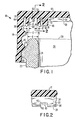
- Figure 1 shows a sectional, side elevation view of a portion of a plastic closure cap and showing the cap only partially secured to the container;
- Figure 2 shows a cross-sectional view of the closure cap of Figure 1 taken on the line 2-2 of Figure 1; and
- Figure 3 shows a sectional, side elevation view generally similar to Figure 1 and showing the closure cap completely secured to the container.
- In Figure 1 there is shown a preferred embodiment of a
plastic closure cap 10.Plastic closure cap 10 is formed or moulded from any suitable plastic composition and has a flat circular top 12 and a downwardly depending,cylindrical side wall 14. Theinner surface 16 ofsidewall 14 may be provided with suitableinternal screw threads 18. Suitable co-operatingexternal screw threads 20 are formed on the outerperipheral surface 22 of acontainer neck 24 which terminates in anopen mouth 26 defined by an upper, somewhat roundedneck finish surface 28. The container may. be made of glass, plastic, or other suitable material and may be designed to hold a carbonated beverage. - A pair of spaced inner and
outer sealing flanges inner surface 34 of thetop portion 12 ofclosure cap 10. As may be seen in Figure 1, these sealing flanges are flaired slightly outwardly at an angle of generally about 100from vertical and are therefore generally in the shape of a truncated cone. Each of these sealing flanges is also preferably slightly tapered in thickness and in the preferred embodiment has a thickness of generally about 0.030" at its point of attachment to theundersurface 34 ofclosure cap top 12, and a thickness of generally about 0.025" at afree end 36. It will be understood that these above recited dimensions as well as those to be set forth subsequently are given primarily for illustrative purposes and are subject to normal manufacturing tolerances which may be generally in the range of +/- 0.010" and +/- 5 °. - Referring again to Figure 1, several dimensional criteria will now be discussed. A horizontal seal interference distance A or B is shown as the horizontal spacing or offset between the point of attachment of the sealing surface side of each sealing
flange container neck 24. Variation of this horizontal seal interference width or spacing is accomplished by moving the sealingflanges container neck 24 remains constant over a range of bottle mouth sizes, movement of the sealingflanges neck finish 28 of the container. These horizontal seal interference distances A and B must always be a positive number for the sealingflanges - As was alluded to previously, this horizontal seal interference distance or width must be increased as the size of the closure cap increases. Referring briefly to Figure 3, it will be seen that the
neck finish surface 28 of thecontainer neck 26 engages the inner surfaces ofseal flanges container neck finish 28 and sealingflanges flanges 
- Several other dimensional relationships are also important for proper seal operation. As may again be seen in Figure 1, the
container neck 24 has a width indicated at E. The closure cap's sealing flanges terminate in tapered free ends 36, each of which tapers to anedge 38. The spacing between thesefree edges 38 can be seen at C and can be referred to as the maximum throat width of the seal flanges. Width C must be greater than container neck thickness E for the sealing flanges to be properly positioned on both sides of theneck finish 28, as seen in Figure 3. A minimum throat width is shown at D and is the spacing between the twoseal flanges inner surface 34 ofclosure cap top 12. The minimum throat width D must be less than width E for the sealing flanges to be deflected outwardly during seal formation. It is this spacing D which determines the horizontal seal interference distance A and B. It will be seen that the sum of A, B and D equals width E. - Referring again to Figures 1 and 3 several additional important aspects of
container closure cap 10 will now be discussed in greater detail. An inner seal back-up flange is shown generally at 40 and is in the shape of a downwardly depending flange positioned radially interiorly ofinner seal flange 30 onsurface 34 ofclosure cap top 12. This inner seal back-upflange 40 is thicker thaninner seal flange 30 and, in the preferred embodiment, has a thickness of generally about 0.035" and a length in the range of generally 0.10". Anabutment surface 42 is formed on inner seal back-upflange 40 as the outer vertical peripheral surface of back-upflange 40. Thisabutment surface 42 is spaced radially inwardly of the radial inner surface offree end 36 of inner sealing flange 30 a distance of generally about 0.025". - An outer back-up
abutment surface 44 is formed as a thickened wall portion of closurecap side wall 14. The spacing betweenabutment surface 44 and the radially outerfree end 36 of outer sealingflange 32 in the non-distorted mode seen in Figure 1 is similar to that ofinner seal flange 30 from inner sealflange abutment surface 42 and is also generally about 0.025". While the inner andouter seal flanges inner surface 34 ofcap top 12, the inner sealflange abutment surface 42 and the outerseal abutment surface 44 are generally vertical. Thus the spacing betweensurfaces outer sealing flanges inner surface 34 increases. -
As'the closure cap 10 is secured tocontainer neck 24 by engagement ofcap threads 18 withcontainer threads 20, thecontainer neck finish 28 is positioned between the sealingflanges flanges abutment surfaces outer sealing flanges container neck finish 28, as may be seen in Figure 3. The greater the area of surface contact between the sealingflanges container neck surface 28, the more effective the seal that is formed will be. By placing the abutment surfaces 42 and 44 so that they will contact the sealingflanges flanges container neck finish 28 in a manner which would result in only a line contact. Particularly when thecontainer closure cap 10 is used with carbonated beverages that generate high internal pressures, the maximisation of seal contact areas is of substantial importance. The co-operation of the sealing flange free ends 36 with the seal flange abutment surfaces 42 and 44 provides this maximum surface area sealing flange to container neck finish contact. - A load stop ring, generally at 50 may be seen in Figure 1 and 3.
Load stop ring 50 is formed integrally withinner surface 34 ofclosure cap top 12, and is located between, and separate from inner andouter seal flanges load stop ring 50 has a height of generally about 0.020" to 0.025". As may be seen in Figure 3, whenclosure cap 10 is secured tocontainer neck 24, a lower,planar surface 52 ofload stop ring 50 abuts the upper surface ofcontainer neck finish 28. As its name implies, theload stop ring 50 prevents a top load imposed on thecap 10 from moving the cap downwardly and thereby interfering with the function of the sealingflanges load stop ring 50 were omitted and with the minimum throat width D being less than container neck finish thickness E, an excessive top load applied to cap 10 could cause over deflection of the sealing flanges and seal malfunction. Theload stop ring 50 prevents this.Load stop ring 50 is made separate from inner andouter sealing flanges load stop ring 50 extended completely between the sealing flanges, it could compromise the ability of the sealing flanges to deflect thereby reducing the sealing surface area.Load stop ring 50 is given sufficient width to perform its intended function without interfering with the functioning of the sealing flanges. - Returning now to Figures 1 and 2 it will be noted that each sealing
flange vent slots 60 formed generally at thefree end 36 of each of the sealing flanges. The width and spacing of thesevent slots 60 may be varied in accordance with the degree of venting required. Thevent slots 60 have a height, in the preferred embodiment, of generally about one-third of the height of the sealing flange. While this height can also be varied, it must not be great enough to unduly increase the flexibility of the sealing flanges or to interfere with the proper contact of the sealing flanges with the container neck finish. These ventslots 60, which are preferably located opposite each other on the inner andouter sealing flanges vent slots 60 provide a safer, more gradual pressure release which is also effective in reducing the tendency of carbonated beverages in containers to overflow when the closure cap is removed. - A plurality of
anti-doming ribs 70 are also formed on theinner surface 34 ofclosure cap 12. Theseanti-doming rib 70 prevent the pressure of a carbonated beverage or the like, in a container to which the closure may be applied, from causing thecap top 12 to bulge or dome outwardly into a convex shape. In the preferred embodiment, theseanti-doming ribs 70 have a height of up to 0.060" and extend radially outwardly from the centre of cap top 12 in a manner similar to the spokes on a wheel. Each suchanti-doming rib 70 extends radially outwardly until it abuts aninner surface 72 of inner seal back-upflange 40. As such theseanti-doming ribs 70 also function to reinforce the inner seal back-upflange 40 and stiffen it. - The plastic container closure cap of this embodiment provides several features which render the cap particularly useful in forming a tight, reliable seal. Increase of the horizontal seal interference width with increased cap size compensates for increased seal flange flexibility as the cap size increases and ensures sufficient seal flange contact area over varying cap sizes. The use of the seal back-up abutment surfaces which are contacted by the free ends of the sealing flanges, and which limit the outward deformation of the seal flanges, ensure that the sealing flanges wrap around the container mouth and have more than a mere line contact with the container neck finish. The load stop ring allows the closure cap to support the top loading required by bottlers without seal failure. The vent slots in the seal flanges add a safety and convenience feature and the anti-doming ribs prevent the cap from bulging outwardly. Each of these features individually and in combination enhances the closure cap and makes it particularly suited for useage in situations which require a tight seal such as with carbonated beverage containers.
- It will be obvious to one skilled in the art that a number of changes may be made to the closure cap of the above embodiment. By way of example, modifications may include the type of screw threads, the inclusion of various tamper evident means, and changes in the types of plastics materials used.
Claims (8)
1. A closure cap for use with a container, comprising a generally circular cap top (12) having an outer surface and an inner surface (34), a generally cylindrical side wall (14) joined at a first end to a peripheral portion of said cap top (12) and including means (18) for securing said closure cap (10) to a container, a pair of spaced inner and outer downwardly extending sealing flanges (30,32), each of said sealing flanges (30,32) being joined at a first end to said inner surface (34) of said cap top (12), said inner and outer sealing flanges (30,32) each having a free end (36) with said free ends (36) being spaced from each other at a distance greater than.the spacing (D) of said first ends of said sealing flanges (30,32), inner and outer sealing flange back-up abutment surfaces (42,44) wherein said inner and outer abutment surfaces (42,44) are engageable by said free ends (36) of said inner and outer sealing flanges (30,32), respectively to limit deflection of said inner and outer sealing flanges (30,32) when said closure cap (10) is secured to a container, and wherein said inner surface (34) of said cap top (12)is generally planar.
2. A closure cap as claimed in Claim 1, further comprising a load stop ring (50), said load stop ring (50)being positioned on said inner surface (34) of said cap top (12) intermediate and spaced from said inner and outer sealing flanges (30,32) and extending downwardly between said inner and outer sealing flanges (30,32).
3. A closure cap as claimed in either Claim 1 or Claim 2, further comprising a plurality of vent slots (60) in each of said sealing flanges (30,32), at ' their free ends.
4. A closure cap as claimed in any one of Claims 1 to 3, wherein said inner sealing flange back-up abutment surface (42) is formed as a radially outer surface of an inner seal back-up flange (40) which flange (40) has a thickness greater than the thickness of said inner sealing flange (30), and wherein said inner sealing flange back-up abutment surface (42) is generally perpendicular to said inner surface (34) of said closure cap top (10).
5. A closure cap as claimed in any one of Claims 1 to 4, wherein said outer sealing flange back-up abutment surface (44) is formed as a portion of said cylindrical side wall (14) of said closure cap (10) at said first end of said cylindrical side wall (14), said outer abutment surface (44) being generally perpendicular to said inner surface (34) of said closure cap top (12).
6. A closure cap as claimed in any one of Claims 1 to 5, further including anti-doming ribs (70) on said inner surface (34) of said closure cap top (12).
7. A closure cap as claimed in Claim 6, wherein said anti-doming ribs (70) extend radially outwardly from a central portion of said inner surface (34) of said closure cap top (12).
8. A plurality of closure caps having a range of sizes for use with containers having a corresponding range of mouth sizes, each said closure cap (10) comprising a generally circular cap top (12) having an inner surface (34); a generally cylindrical side wall (14) joined at a first end to a peripheral portion of said cap top (12) and including means (18) for securing said closure cap (10)to a container; a pair of radially spaced inner and outer, downwardly extending circumferential sealing flanges (30,32), each of said sealing flanges (30,32) being joined at a first end to said inner surface (34) of said cap top, said inner and outer sealing flanges (30,32) each having a free end (36) with said free ends (36) being spaced from each other at a distance greater than the spacing (D) of said first ends of said sealing flanges (30,32), a radially outer surface of said inner flange and a radially inner surface of said outer flange (32) for engaging inner and outer edge portions, respectively of the container mouth; a horizontal seal interference distance (A,B), said distance (A,B) being the horizontal offsets between the points of attachment of said radially outer surface of said inner flange (30) and said radially inner surface (34) of said outer flange (32) to said inner surface of said cap top and said inner and outer edge portions of the container mouth, inner and outer sealing flange back-up abutment surfaces (40,42), wherein horizontal seal interference distance (A,B) varies proportionally with said closure cap size in said range of closure cap sizes; and said inner and outer abutment surfaces (42,44) being engageable by said free ends (36)of said inner and outer sealing flanges (30,32), respectively, to limit deflection of said inner and outer sealing flanges (30,32) when said closure cap (10)is secured to a container and said inner surface (34) is planar at the location of the flanges (30,32) joined thereto.
Applications Claiming Priority (2)
| Application Number | Priority Date | Filing Date | Title |
|---|---|---|---|
| US654084 | 1984-09-25 | ||
| US06/654,084 US4560077A (en) | 1984-09-25 | 1984-09-25 | Plastic closure cap |
Publications (2)
| Publication Number | Publication Date |
|---|---|
| EP0176205A2 true EP0176205A2 (en) | 1986-04-02 |
| EP0176205A3 EP0176205A3 (en) | 1988-05-04 |
Family
ID=24623376
Family Applications (1)
| Application Number | Title | Priority Date | Filing Date |
|---|---|---|---|
| EP85305709A Withdrawn EP0176205A3 (en) | 1984-09-25 | 1985-08-12 | A closure cap |
Country Status (3)
| Country | Link |
|---|---|
| US (1) | US4560077A (en) |
| EP (1) | EP0176205A3 (en) |
| AU (1) | AU4611385A (en) |
Cited By (9)
| Publication number | Priority date | Publication date | Assignee | Title |
|---|---|---|---|---|
| GB2264108A (en) * | 1992-01-24 | 1993-08-18 | Beeson & Sons Ltd | A container and a closure therefor |
| EP0587325A1 (en) * | 1992-09-11 | 1994-03-16 | Kraft Foods, Inc. | Sealed container |
| US6257432B1 (en) | 1999-12-29 | 2001-07-10 | Phoenix Closures, Inc. | Cap and container assembly |
| US6260722B1 (en) | 1999-12-29 | 2001-07-17 | Phoenix Closures, Inc. | Cap and container assembly |
| WO2004110888A1 (en) * | 2003-06-10 | 2004-12-23 | Alcoa Closure Systems Japan, Limited | Synthetic resin cap, closing device, and container-packed beverage |
| FR2863589A1 (en) | 2003-12-12 | 2005-06-17 | Bericap | Container e.g. PET bottle, cap, has main portions, of inner and outer sides of outer and inner lips, converging and diverging from their bases in direction of their free ends, respectively and inclined with angles between 0 and 10 degree |
| KR100654008B1 (en) | 2005-09-07 | 2006-12-05 | 주식회사 두산 | A lid for reinforce leakage prevention |
| EP1985549A1 (en) | 2004-09-01 | 2008-10-29 | Creanova Universal Closures Ltd. | Sealing means for a closure, closure and process |
| US8393483B2 (en) | 2004-09-01 | 2013-03-12 | Creanova Universal Closure Ltd. | Sealing means for closure with multiple sealing areas |
Families Citing this family (66)
| Publication number | Priority date | Publication date | Assignee | Title |
|---|---|---|---|---|
| GB2189228A (en) * | 1986-04-18 | 1987-10-21 | John Stewart Hamilton | Screw threaded aseptic closure |
| FR2597440B1 (en) * | 1986-04-18 | 1989-04-28 | Seiwerling Robert | QUICK CLOSING CONTAINER |
| US4905852A (en) * | 1989-05-26 | 1990-03-06 | Zapata Industries, Inc. | Plastic closure with improved seal |
| US5101993A (en) * | 1990-05-10 | 1992-04-07 | Phoenix Closures, Inc. | Closure seal |
| DE4128474A1 (en) † | 1991-08-28 | 1993-03-04 | Berg Jacob Gmbh Co Kg | PLASTIC SCREW CAP FOR PRESSURIZED BOTTLES |
| US5297688A (en) * | 1992-03-03 | 1994-03-29 | Creative Packaging Corp. | Closure for sealing a container rim |
| US5320236A (en) * | 1992-04-27 | 1994-06-14 | Owens-Illinois Closure Inc. | Plastic container package with linerless sealing closure system |
| ES2119132T3 (en) * | 1993-12-23 | 1998-10-01 | Crown Cork Ag | SYNTHETIC MATERIAL CLOSING CAP WITH INTERIOR SEAL WITH EARLY VENTILATION. |
| US5785196A (en) * | 1995-05-31 | 1998-07-28 | Rexam Closures Inc. | Closure for a pressurized container |
| US7107783B2 (en) * | 1997-09-19 | 2006-09-19 | Advanced Porcus Technologies, Llc | Self-cooling containers for liquids |
| US20040173556A1 (en) * | 1997-09-19 | 2004-09-09 | Smolko Daniel D. | Vented closures for containers |
| BR9813274A (en) * | 1997-10-25 | 2000-08-22 | Safety Cap System Ag | Plastic screw cap for closing a bottle or similar |
| US6477823B1 (en) * | 1998-07-30 | 2002-11-12 | Kerr Group, Inc. | Closure and container system for hot filled containers |
| EP0987191A1 (en) * | 1998-09-14 | 2000-03-22 | Crown Cork & Seal Technologies Corporation | Closure cap |
| EP0987190A1 (en) * | 1998-09-14 | 2000-03-22 | Crown Cork & Seal Technologies Corporation | Closure cap |
| US6202870B1 (en) * | 1999-03-29 | 2001-03-20 | Woodrow W. Pearce | Venting cap |
| KR20010096600A (en) * | 2000-03-13 | 2001-11-07 | 도케 케이시 | Synthetic resin container closure |
| US6382445B1 (en) | 2000-06-23 | 2002-05-07 | Alcoa Closure Systems International | Linerless closure with pressure seal holding feature |
| US6491175B1 (en) * | 2000-06-28 | 2002-12-10 | Saad Taha | Single piece closure for a pressurized container |
| GB2369114B (en) * | 2000-11-21 | 2004-05-05 | Beeson & Sons Ltd | Plug seals for user-friendly cap assemblies |
| ES2225058T3 (en) * | 2000-12-22 | 2005-03-16 | Prispa Holding S.A. | CAP FOR CONTAINERS FOR LIQUID PRODUCTS. |
| DE10297200B4 (en) * | 2001-09-10 | 2010-09-16 | Closures And Packaging Services Ltd. | Closure for container openings |
| GB2407561B (en) * | 2001-09-10 | 2006-03-08 | Closures & Packaging Serv Ltd | Linerless bore seal closure |
| US6802428B2 (en) * | 2002-02-15 | 2004-10-12 | Phoenix Closures, Inc. | Apparatus and method allowing gas flowing into and/or out of container |
| US20030161980A1 (en) * | 2002-02-27 | 2003-08-28 | Nelson Brent S. | Plastic container |
| GB0210593D0 (en) * | 2002-05-09 | 2002-06-19 | Ici Plc | A large can for a brushable coating composition which is sealingly closeable by a screw-thread lid |
| US20040188375A1 (en) * | 2002-07-03 | 2004-09-30 | Fabricas Monterrey, S.A. De C.V. | Linerless plastic closure with a sealing lip |
| US6997354B2 (en) * | 2002-07-19 | 2006-02-14 | Rieke Corporation | Sealing mechanisms for use in liquid-storage containers |
| DE10245595A1 (en) * | 2002-09-30 | 2004-04-08 | Bericap Gmbh & Co. Kg | Screw cap for pressurized containers |
| BRPI0415003B1 (en) * | 2003-10-01 | 2018-09-25 | Obrist Closures Switzerland | plastic cap for a container with sealing strip inclined radially toward the finish of the neck, and that container |
| JP4423937B2 (en) * | 2003-11-19 | 2010-03-03 | 株式会社吉野工業所 | Refill container |
| US7527159B2 (en) | 2004-03-11 | 2009-05-05 | Rexam Closure Systems Inc. | Threaded child-resistant package having linerless closure |
| US7819264B2 (en) * | 2003-12-03 | 2010-10-26 | Rexam Closure Systems Inc. | Child-resistant closure, container and package |
| JP4769433B2 (en) * | 2004-06-09 | 2011-09-07 | 東洋製罐株式会社 | Plastic cap |
| EP1627821B1 (en) * | 2004-08-17 | 2007-05-02 | PackSys Global (Switzerland) Ltd. | Screw cap for a container |
| PL1799573T3 (en) * | 2004-09-01 | 2009-05-29 | Creanova Universal Closures Ltd | Closure |
| EP1679267B1 (en) * | 2004-12-16 | 2011-03-30 | Japan Crown Cork Co. Ltd. | Plastic cap featuring excellent sealing and venting |
| US7651004B2 (en) * | 2005-05-12 | 2010-01-26 | Rexam Closure Systems Inc. | Linerless closure and package |
| GB2432360A (en) * | 2005-11-25 | 2007-05-23 | Beeson & Sons Ltd | Jaw seals for container closure assemblies |
| US7963419B2 (en) * | 2006-02-23 | 2011-06-21 | Bway Corporation | Lid and container |
| US8181819B2 (en) | 2006-02-23 | 2012-05-22 | Bway Corporation | Lid and container |
| WO2007147206A1 (en) * | 2006-06-19 | 2007-12-27 | Amcor Limited | A closure and a bottle neck |
| US20080110851A1 (en) * | 2006-10-13 | 2008-05-15 | Owens-Illinois Closure Inc. | Dual seal closure and package |
| US7891512B2 (en) * | 2006-12-06 | 2011-02-22 | Reckitt Benckiser Inc. | Linerless closure for a container |
| US7712624B2 (en) * | 2006-12-27 | 2010-05-11 | Kraft Foods Holdings, Inc. | Plastic coffee container with top load support by particulate product |
| US8056744B2 (en) * | 2007-01-12 | 2011-11-15 | Phoenix Closures, Inc. | Closure with ring ribs |
| CA2577886C (en) * | 2007-02-13 | 2015-09-08 | Crealise Conditionnement Inc. | Plug without inserted seal |
| JP3142618U (en) * | 2008-04-08 | 2008-06-19 | ロート製薬株式会社 | Container for liquid |
| US20090294322A1 (en) * | 2008-06-02 | 2009-12-03 | Baltz Kyle L | Pail with skirt and lid |
| US7922028B2 (en) * | 2009-02-25 | 2011-04-12 | Rehrig Pacific Company | Pail with lid and flashed lip |
| AU2011203587A1 (en) * | 2010-01-06 | 2012-08-09 | Daniel P. Soehnlen | Combined lip and shoulder seal for threaded cap |
| KR101950054B1 (en) | 2012-01-06 | 2019-02-19 | 클로져 시스템즈 인터내셔날 인크. | Linerless closure |
| EP2897873B1 (en) | 2012-09-19 | 2019-09-25 | Vetropack Holding AG | Bottle opening for twist-off crown cap with splintering protection |
| AT13725U1 (en) * | 2012-09-19 | 2014-07-15 | Vetropack Austria Gmbh | Turn-cap cork with chipping protection |
| ITMO20120253A1 (en) | 2012-10-18 | 2014-04-19 | Sacmi | CAP FOR CONTAINERS. |
| US9428292B2 (en) | 2013-03-13 | 2016-08-30 | Silgan White Cap LLC | Fluid injection system and method for supporting container walls |
| USD712703S1 (en) | 2013-09-06 | 2014-09-09 | Kraft Foods Group Brands Llc | Container for food product |
| WO2015151286A1 (en) * | 2014-04-04 | 2015-10-08 | サントリーホールディングス株式会社 | Resin cap |
| JP6088118B1 (en) * | 2016-01-04 | 2017-03-01 | 株式会社メガハウス | Bottle cap |
| US20200354116A1 (en) * | 2017-11-03 | 2020-11-12 | Container International, Inc. | Seal for container lids and container lids and container assemblies having same |
| US10407225B2 (en) * | 2017-11-07 | 2019-09-10 | Closure Systems International Inc. | Closure and package that vents at high pressure |
| EP3737615A4 (en) | 2018-01-10 | 2022-01-26 | Bway Corporation | Container and container lid with built-in brine disc |
| USD894510S1 (en) | 2019-01-10 | 2020-08-25 | Bway Corporation | Container |
| USD928555S1 (en) | 2019-01-10 | 2021-08-24 | Bway Corporation | Container lid |
| US20220281648A1 (en) * | 2019-07-16 | 2022-09-08 | Jin Hee Ahn | Container cap and container combined with same |
| KR102611394B1 (en) * | 2020-03-12 | 2023-12-08 | 주식회사 아워홈 | Cap portion and storing vessel of fermented food having the same |
Citations (4)
| Publication number | Priority date | Publication date | Assignee | Title |
|---|---|---|---|---|
| GB854571A (en) * | 1957-11-07 | 1960-11-23 | Fenwal Lab Inc | Improvements in or relating to a container closure system |
| US3944104A (en) * | 1974-11-25 | 1976-03-16 | Consumers Glass Company Limited | Threaded wine bottle stopper |
| US4346812A (en) * | 1981-03-10 | 1982-08-31 | The Continental Group, Inc. | Plastic closure with reinforced central panel |
| US4442947A (en) * | 1983-01-18 | 1984-04-17 | Continental White Cap, Inc. | Plastic closure with sealing flaps |
Family Cites Families (7)
| Publication number | Priority date | Publication date | Assignee | Title |
|---|---|---|---|---|
| US2927709A (en) * | 1959-07-07 | 1960-03-08 | Faultless Rubber Co | Bottle stopple |
| US3255907A (en) * | 1964-01-13 | 1966-06-14 | Wheeling Stamping Co | Linerless screw closure for containers |
| US3215297A (en) * | 1964-03-25 | 1965-11-02 | Anchor Hocking Glass Corp | Closure cap |
| GB1139018A (en) * | 1966-09-28 | 1969-01-08 | Alrik Civer Lindstrom | Screw cap with locking means |
| US4143785A (en) * | 1978-03-16 | 1979-03-13 | Sun Coast Plastic Closures, Inc. | Plastic vacuum sealing cap |
| JPS5746766A (en) * | 1980-09-02 | 1982-03-17 | Crown Cork Japan | Vessel cover with improved liner |
| US4429802A (en) * | 1982-05-28 | 1984-02-07 | Anchor Hocking Corporation | Linerless closure cap |
-
1984
- 1984-09-25 US US06/654,084 patent/US4560077A/en not_active Expired - Lifetime
-
1985
- 1985-08-12 EP EP85305709A patent/EP0176205A3/en not_active Withdrawn
- 1985-08-12 AU AU46113/85A patent/AU4611385A/en not_active Abandoned
Patent Citations (4)
| Publication number | Priority date | Publication date | Assignee | Title |
|---|---|---|---|---|
| GB854571A (en) * | 1957-11-07 | 1960-11-23 | Fenwal Lab Inc | Improvements in or relating to a container closure system |
| US3944104A (en) * | 1974-11-25 | 1976-03-16 | Consumers Glass Company Limited | Threaded wine bottle stopper |
| US4346812A (en) * | 1981-03-10 | 1982-08-31 | The Continental Group, Inc. | Plastic closure with reinforced central panel |
| US4442947A (en) * | 1983-01-18 | 1984-04-17 | Continental White Cap, Inc. | Plastic closure with sealing flaps |
Cited By (16)
| Publication number | Priority date | Publication date | Assignee | Title |
|---|---|---|---|---|
| GB2264108A (en) * | 1992-01-24 | 1993-08-18 | Beeson & Sons Ltd | A container and a closure therefor |
| GB2264108B (en) * | 1992-01-24 | 1995-11-15 | Beeson & Sons Ltd | A container closure assembly |
| EP0587325A1 (en) * | 1992-09-11 | 1994-03-16 | Kraft Foods, Inc. | Sealed container |
| US5383558A (en) * | 1992-09-11 | 1995-01-24 | Kraft General Foods, Inc. | Sealed container |
| US5931323A (en) * | 1992-09-11 | 1999-08-03 | Kraft Foods, Inc. | Sealed container |
| US6257432B1 (en) | 1999-12-29 | 2001-07-10 | Phoenix Closures, Inc. | Cap and container assembly |
| US6260722B1 (en) | 1999-12-29 | 2001-07-17 | Phoenix Closures, Inc. | Cap and container assembly |
| AU2003244106B2 (en) * | 2003-06-10 | 2008-03-20 | Alcoa Closure Systems Japan, Limited | Synthetic resin cap, closing device, and container-packed beverage |
| EP1634818A1 (en) * | 2003-06-10 | 2006-03-15 | Alcoa Closure Systems Japan, Limited | Synthetic resin cap, closing device, and container-packed beverage |
| EP1634818A4 (en) * | 2003-06-10 | 2007-06-06 | Alcoa Closure Systems Japan | Synthetic resin cap, closing device, and container-packed beverage |
| WO2004110888A1 (en) * | 2003-06-10 | 2004-12-23 | Alcoa Closure Systems Japan, Limited | Synthetic resin cap, closing device, and container-packed beverage |
| AU2003244106B9 (en) * | 2003-06-10 | 2008-07-24 | Alcoa Closure Systems Japan, Limited | Synthetic resin cap, closing device, and container-packed beverage |
| FR2863589A1 (en) | 2003-12-12 | 2005-06-17 | Bericap | Container e.g. PET bottle, cap, has main portions, of inner and outer sides of outer and inner lips, converging and diverging from their bases in direction of their free ends, respectively and inclined with angles between 0 and 10 degree |
| EP1985549A1 (en) | 2004-09-01 | 2008-10-29 | Creanova Universal Closures Ltd. | Sealing means for a closure, closure and process |
| US8393483B2 (en) | 2004-09-01 | 2013-03-12 | Creanova Universal Closure Ltd. | Sealing means for closure with multiple sealing areas |
| KR100654008B1 (en) | 2005-09-07 | 2006-12-05 | 주식회사 두산 | A lid for reinforce leakage prevention |
Also Published As
| Publication number | Publication date |
|---|---|
| EP0176205A3 (en) | 1988-05-04 |
| US4560077A (en) | 1985-12-24 |
| AU4611385A (en) | 1986-04-10 |
Similar Documents
| Publication | Publication Date | Title |
|---|---|---|
| EP0176205A2 (en) | A closure cap | |
| CA1163234A (en) | Container-closure arrangement | |
| US5782369A (en) | Linerless closure for container | |
| US5785196A (en) | Closure for a pressurized container | |
| US5836466A (en) | Safety closure and container assembly | |
| EP0132992A2 (en) | Bottle closure | |
| US4079857A (en) | Containers and closures | |
| US3189072A (en) | Container outlet and closure therefor | |
| JP3382964B2 (en) | Fraudulent plastic closure | |
| US5259522A (en) | Linerless closure | |
| US3117702A (en) | Pouring nozzle with captive cap | |
| US3907146A (en) | Primary closure | |
| US6382445B1 (en) | Linerless closure with pressure seal holding feature | |
| US6126027A (en) | Self-centering container closure | |
| US6044994A (en) | Sealing arrangement for closure caps having liners | |
| EP0119788A2 (en) | Improvements relating to closures | |
| GB2068914A (en) | Side seal closure | |
| US3369694A (en) | Container with lid closure | |
| US3814274A (en) | Linerless closure for a container | |
| US3994410A (en) | Plastic bottle cap | |
| JPH0440268B2 (en) | ||
| EP0072252B1 (en) | Closure and container neck structure therefor | |
| US4421247A (en) | Two-piece quad-seal closure with plug shock absorbing end panel | |
| EP0078292B1 (en) | Safety closure containers | |
| IE41402B1 (en) | Plastics closure bushing |
Legal Events
| Date | Code | Title | Description |
|---|---|---|---|
| PUAI | Public reference made under article 153(3) epc to a published international application that has entered the european phase |
Free format text: ORIGINAL CODE: 0009012 |
|
| AK | Designated contracting states |
Kind code of ref document: A2 Designated state(s): AT BE CH DE FR GB IT LI LU NL SE |
|
| PUAL | Search report despatched |
Free format text: ORIGINAL CODE: 0009013 |
|
| AK | Designated contracting states |
Kind code of ref document: A3 Designated state(s): AT BE CH DE FR GB IT LI LU NL SE |
|
| STAA | Information on the status of an ep patent application or granted ep patent |
Free format text: STATUS: THE APPLICATION IS DEEMED TO BE WITHDRAWN |
|
| 18D | Application deemed to be withdrawn |
Effective date: 19880228 |
|
| RIN1 | Information on inventor provided before grant (corrected) |
Inventor name: DUTT, HERBERT VINCENT |