EP0176116A2 - Remote control system for hearing aids - Google Patents
Remote control system for hearing aids Download PDFInfo
- Publication number
- EP0176116A2 EP0176116A2 EP85201185A EP85201185A EP0176116A2 EP 0176116 A2 EP0176116 A2 EP 0176116A2 EP 85201185 A EP85201185 A EP 85201185A EP 85201185 A EP85201185 A EP 85201185A EP 0176116 A2 EP0176116 A2 EP 0176116A2
- Authority
- EP
- European Patent Office
- Prior art keywords
- control signal
- hearing aid
- unit
- combination
- remote control
- Prior art date
- Legal status (The legal status is an assumption and is not a legal conclusion. Google has not performed a legal analysis and makes no representation as to the accuracy of the status listed.)
- Granted
Links
Images
Classifications
-
- H—ELECTRICITY
- H04—ELECTRIC COMMUNICATION TECHNIQUE
- H04R—LOUDSPEAKERS, MICROPHONES, GRAMOPHONE PICK-UPS OR LIKE ACOUSTIC ELECTROMECHANICAL TRANSDUCERS; DEAF-AID SETS; PUBLIC ADDRESS SYSTEMS
- H04R25/00—Deaf-aid sets, i.e. electro-acoustic or electro-mechanical hearing aids; Electric tinnitus maskers providing an auditory perception
- H04R25/55—Deaf-aid sets, i.e. electro-acoustic or electro-mechanical hearing aids; Electric tinnitus maskers providing an auditory perception using an external connection, either wireless or wired
- H04R25/558—Remote control, e.g. of amplification, frequency
-
- H—ELECTRICITY
- H04—ELECTRIC COMMUNICATION TECHNIQUE
- H04R—LOUDSPEAKERS, MICROPHONES, GRAMOPHONE PICK-UPS OR LIKE ACOUSTIC ELECTROMECHANICAL TRANSDUCERS; DEAF-AID SETS; PUBLIC ADDRESS SYSTEMS
- H04R25/00—Deaf-aid sets, i.e. electro-acoustic or electro-mechanical hearing aids; Electric tinnitus maskers providing an auditory perception
- H04R25/55—Deaf-aid sets, i.e. electro-acoustic or electro-mechanical hearing aids; Electric tinnitus maskers providing an auditory perception using an external connection, either wireless or wired
- H04R25/554—Deaf-aid sets, i.e. electro-acoustic or electro-mechanical hearing aids; Electric tinnitus maskers providing an auditory perception using an external connection, either wireless or wired using a wireless connection, e.g. between microphone and amplifier or using Tcoils
-
- H—ELECTRICITY
- H04—ELECTRIC COMMUNICATION TECHNIQUE
- H04R—LOUDSPEAKERS, MICROPHONES, GRAMOPHONE PICK-UPS OR LIKE ACOUSTIC ELECTROMECHANICAL TRANSDUCERS; DEAF-AID SETS; PUBLIC ADDRESS SYSTEMS
- H04R2225/00—Details of deaf aids covered by H04R25/00, not provided for in any of its subgroups
- H04R2225/51—Aspects of antennas or their circuitry in or for hearing aids
Definitions
- the invention relates to a combination of a hearing aid, being adapted to be supported upon the head of a user of the aid, and a remote control unit, the remote control unit comprising, control means, that can mannually be operated by the user, an encoder unit having an input coupled to the control means and an output, and a transmitter having an input coupled to the output of the encoder unit, the encoder unit being adapted to convert control operations carried out by the user on the control means into a first control signal and to apply this first control signal via its output to the transmitter, for the wireless transmission of the first control signal, the hearing aid comprising a pick-up for receiving the first control signal transmitted by the transmitter of the remote control unit, a decoder unit having an input coupled to the pick-up for receiving the first control signal and an output, the decoder unit being adapted to convert the first control signal into a second control signal for controlling at least one operational parameter of the hearing aid.
- the invention further relates to a remote control unit and a hearing aid for use in the combination. The combination described in
- Headworn hearing aids of the eyeglass, behind-the-ear, in-the-ear or in-the-earcanal type generally contain a miniature microphone and a miniature receiver as well as an electronic amplifier for signal amplification and/or filtering.
- coils occupy a large amount of space, which is sometimes even not available at all, such as in the in-the-earcanal type.
- the hearing aids are either very bulky, or it is not even possible to apply a remote control to the aid, which remote control can hardly be dispensed with in the in-the-earcanal type hearing aid.
- the invention aims at providing an other way of realizing the remote control of the hearing aid, such that the hearing aids can remain rather small and occupy a smaller amount of space, which means that the remote control of the in-the-earcanal type hearing aid will be possible.
- the combination is characterized in that the wireless transmission of the first control signal takes place by means of acoustic waves.
- the inventions is based on the recognition that the transmission of acoustic waves makes it necessary to use a pick-up in the form of an acousto-electric transducer.
- Such transducers can be smaller than a coil, so that a saving of space can be obtained.
- the invention describes a system to control a hearing aid remotely by means of a hand-held device which is brought in the vicinity of or held against the hearing aid concerned. Control is through more or less simple sound signals originated by the handheld unit and received by the pick-up of the aid.
- the said microphone can function as the "pick-up for receiving the first control signal.
- the pick-up is needed, which realizes an even larger saving of space, so that the hearing aid can be even smaller.
- filter means are needed for deriving the first control signal from the output signal of the microphone, an output of the filter means being coupled to the input of the decoder unit.
- the first control signal can lie in a frequency region which ia outside the operating frequency range of the receiver.
- the general characteristic of modern miniature transducers which enable miniature microphones to be made much more wideband (say up to 12, 15 or 20 kHz) than receivers (hearing aid telephones) which, because of their own frequency characteristic as well as the influence of the acoustic coupling of the earcavity to the receiver, ingenerally does not extend beyond 6 or 7 kHz.
- This difference in bandwidth is used to bring the first control signal into the aid to switch the aid on or off, or to change volume, frequency-settings or other operational parameters of the aid, without disturbing the user of the aid.
- the first control signal is simply picked up by the microphone but cannot be reproduced by the receiver with its specific termination.
- the pick-up - and in those cases where the microphone of the hearing aid functions as the pick-up, the microphone - as well as the decoder unit in the hearing aid should be permanently switched on.
- the wireless transmission of the first control signal can take place by means of ultrasonic waves. This means that the frequency of these waves lie outside the frequency range of normal hearing.
- the wireless transmission occurs via modulated acoustic waves. This makes the combination less sensitive for disturbing acoustic signals originating from other sources.
- the first control signal can be transmitted in amplitude-modulated or frequency-modulated form.
- the encoder unit in the remote control unit comprises a modulator in order to modulate the control signal
- the decoder unit in the hearing aid comprises a demodulator in order to demodulate the control signal received.
- encoding techniques can alternatively be applied, such as an encoding based on tone combinations (e.g. the so-called “dual tone multi frequency. system, as applied in the transmission of dialling information over telephone lines).
- tone combinations e.g. the so-called “dual tone multi frequency. system, as applied in the transmission of dialling information over telephone lines).
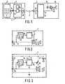
- FIG. 1 shows an embodiment of the combination of a hearing aid 1 and a remote control unit 2, both elements being shown only schematically, in the form of block diagrams.
- the remote control unit 2 comprises control means 3, e.g. in the form of a tablet having control buttons 4.
- the output 5 of the control means 3 is coupled to an input 6 of an encoder unit 7.
- An output 8 of the encoder unit 7 is coupled to an input 9 of a transmitter 10, which is in the form of a loudspeaker.
- the encoder unit is adapted to convert control operations carried out by a user of the hearing aid on the control means 3 into a first control signal and to apply the first control signal via its output 8 to the transmitter 10, for the wireless transmission of the first control signal, which wireless transmission takes place by means of acoustic waves 11.
- the transmission can take place by means of ultrasonic waves.
- the transducer 10 is an ultrasonic transducer.
- the transmission of the first control signal can alternatively take place by means of modulated acoustic waves.
- the encoder unit 7 comprises a modulator 12 and an oscillator 13. Operating a button 4 of the control means 3 influences either the frequency of the oscillator, or the amplitude of the oscillator, in which case one obtains a frequency-modulated or an amplitude-modulated signal at the output 8 of the encoder unit 7.
- the hearing aid 1 comprises a pick-up 15 for receiving the acousttc waves 11 transmitted by the transmitter 10 of the remote control unit 2.
- the first control signal received is fed to an input 16 of a decoder unit 17.
- the decoder unit 17 is adapted to convert the first control signal into a second control signal for controlling at least one operational parameter of the hearing aid 1.
- the second control signal influences the amplification factor A of an amplifier 19 in the hearing aid.
- the output 18 of the decoder unit 17 is coupled to a control input 20 of the amplifier 19.
- the hearing aid generally comprises a microphone 21 coupled to the amplifier 19 and a loudspeaker (or telephone) 22.
- the decoder unit 17 comprises a demodulator (not shown) to demodulate the first control signal if it is transmitted in frequency-or amplitude-modulated form.
- the decoder unit 17 comprises a memory in which the level of the second control signal can be stored after each manipulation of a button on the remote control unit 2.
- FIG. 2 shows an other embodiment of the hearing aid, denoted by the reference numeral 1'.
- the pick-up 25 also functions as the microphone of the aid. This means that the output of the pick-up 25 is also coupled to the input of the amplifier 19.
- Filter means 26 are included between the microphone 25 and the decoder unit 17. In order to derive the first control signal from the output signal of the microphone 25.
- the filter means 26 can include a band-pass filter covering that frequency range in which the frequency of the first control signal lies.
- the telephone 22 exhibits, because of its acoustical coupling to the earcavity, a limited operating frequency range, up to say 6 or 7 kHz, compared to the operating frequency range of the microphone 25, which is say up to 12, 15 or 20 kHz, one can modulate the first control signal into the frequency region above 7 kHz and below the upper limit frequency of the operative frequency range of the microphone. In that case no bandstop filter is needed in the connection between the point 27 and the amplifier 19 to prevent the first control signal from being reproduced by the telephone 22.
- the embodiment of figure 2 again shows a control of the amplification factor A of the hearing aid amplifier 19.
- FIG 3 shows an embodiment of a hearing aid 1" in which the on-off switch 30 can be manipulated remotely, Switching the on- off switch 30 on realizes a supply voltage V from a battery 31 incorporated in the aid to be fed to the power supply terminal 32 of the amplifier 19 of the aid.
- the microphone 25 and the decoder unit 17 are permanently coupled to the supply voltage V by means of the connections 33 and 34. The same is valid for the band-pass filter 26 if it is an active filter.
Abstract
Description
- The invention relates to a combination of a hearing aid, being adapted to be supported upon the head of a user of the aid, and a remote control unit, the remote control unit comprising, control means, that can mannually be operated by the user, an encoder unit having an input coupled to the control means and an output, and a transmitter having an input coupled to the output of the encoder unit, the encoder unit being adapted to convert control operations carried out by the user on the control means into a first control signal and to apply this first control signal via its output to the transmitter, for the wireless transmission of the first control signal, the hearing aid comprising a pick-up for receiving the first control signal transmitted by the transmitter of the remote control unit, a decoder unit having an input coupled to the pick-up for receiving the first control signal and an output, the decoder unit being adapted to convert the first control signal into a second control signal for controlling at least one operational parameter of the hearing aid. The invention further relates to a remote control unit and a hearing aid for use in the combination. The combination described in the opening paragraph is known from German Offenlegungsschrift 1.938.381.
- Headworn hearing aids of the eyeglass, behind-the-ear, in-the-ear or in-the-earcanal type generally contain a miniature microphone and a miniature receiver as well as an electronic amplifier for signal amplification and/or filtering.
- With hearing aids becoming ever smaller as well as more reliable the on-off switch and the volume control are becoming more and more of a problem. Manipulation of the ever smaller buttons especially for elderly people is a problem, while the switches and controls are generally the weakest part of the aid and more than other elements of aids subject to the environmental conditions.
- A solution for the problems described above can be found in the above-mentioned German Offenlegungsschrift 1.938.381. By means of the inductive coupling between coils in the remote control unit and the hearing aid it is possible to change the operational parameters of the aid, such as switching the aid on and off, changing the amplification factor of the amplifier or amending the frequency response characteristics of the aid.
- However, coils occupy a large amount of space, which is sometimes even not available at all, such as in the in-the-earcanal type. This means that the hearing aids are either very bulky, or it is not even possible to apply a remote control to the aid, which remote control can hardly be dispensed with in the in-the-earcanal type hearing aid.
- The invention aims at providing an other way of realizing the remote control of the hearing aid, such that the hearing aids can remain rather small and occupy a smaller amount of space, which means that the remote control of the in-the-earcanal type hearing aid will be possible. To that purpose the combination is characterized in that the wireless transmission of the first control signal takes place by means of acoustic waves.
- The inventions is based on the recognition that the transmission of acoustic waves makes it necessary to use a pick-up in the form of an acousto-electric transducer. Such transducers can be smaller than a coil, so that a saving of space can be obtained.
- The invention describes a system to control a hearing aid remotely by means of a hand-held device which is brought in the vicinity of or held against the hearing aid concerned. Control is through more or less simple sound signals originated by the handheld unit and received by the pick-up of the aid.
- Especially in a hearing aid comprising a series arrangement of a microphone, an amplifier and a receiver, the said microphone can function as the "pick-up for receiving the first control signal. In this case, no additional element for the pick-up is needed, which realizes an even larger saving of space, so that the hearing aid can be even smaller. Furthermore a saving in energy can be obtained because there is no transducer now instead of two for the receiving of the speech signals and the control signal. However this means that filter means are needed for deriving the first control signal from the output signal of the microphone, an output of the filter means being coupled to the input of the decoder unit.
- the first control signal can lie in a frequency region which ia outside the operating frequency range of the receiver. In this case, one makes use of the general characteristic of modern miniature transducers which enable miniature microphones to be made much more wideband (say up to 12, 15 or 20 kHz) than receivers (hearing aid telephones) which, because of their own frequency characteristic as well as the influence of the acoustic coupling of the earcavity to the receiver, ingenerally does not extend beyond 6 or 7 kHz.
- This difference in bandwidth is used to bring the first control signal into the aid to switch the aid on or off, or to change volume, frequency-settings or other operational parameters of the aid, without disturbing the user of the aid.
- The first control signal is simply picked up by the microphone but cannot be reproduced by the receiver with its specific termination.
- It should be noted that, if a remote control of the on/off function of the hearing aid is contemplated, the pick-up - and in those cases where the microphone of the hearing aid functions as the pick-up, the microphone - as well as the decoder unit in the hearing aid should be permanently switched on.
- The wireless transmission of the first control signal can take place by means of ultrasonic waves. This means that the frequency of these waves lie outside the frequency range of normal hearing.
- It should be noted here that the wireless transmission of signals by means of ultrasonic waves is known per se from German Gebrauchsmuster 73.11.755. However said Gebrauchsmuster concerns the wireless transmission of audio information from an audio system to a headphone. This means that it does not describe the wireless transmission of a control signal for the remote control of an operational parameter of a hearing aid.
- An other possibility is that the wireless transmission occurs via modulated acoustic waves. This makes the combination less sensitive for disturbing acoustic signals originating from other sources. The first control signal can be transmitted in amplitude-modulated or frequency-modulated form. This means that the encoder unit in the remote control unit comprises a modulator in order to modulate the control signal, and the decoder unit in the hearing aid comprises a demodulator in order to demodulate the control signal received.
- However, it should be noted here that other encoding techniques can alternatively be applied, such as an encoding based on tone combinations (e.g. the so-called "dual tone multi frequency. system, as applied in the transmission of dialling information over telephone lines).
- The following figure description describes the invention in more detail with reference to the accompanying drawing. In the drawing shows
- figure 1 a first embodiment,
- figure 2 another embodiment of the hearing aid in the combination and
- figure 3 again another embodiment of the hearing aid in the combination.
- Figure 1 shows an embodiment of the combination of a
hearing aid 1 and a remote control unit 2, both elements being shown only schematically, in the form of block diagrams. The remote control unit 2 comprises control means 3, e.g. in the form of a tablet having control buttons 4. Theoutput 5 of the control means 3 is coupled to an input 6 of an encoder unit 7. An output 8 of the encoder unit 7 is coupled to an input 9 of a transmitter 10, which is in the form of a loudspeaker. The encoder unit is adapted to convert control operations carried out by a user of the hearing aid on the control means 3 into a first control signal and to apply the first control signal via its output 8 to the transmitter 10, for the wireless transmission of the first control signal, which wireless transmission takes place by means ofacoustic waves 11. The transmission can take place by means of ultrasonic waves. This means that the transducer 10 is an ultrasonic transducer. - The transmission of the first control signal can alternatively take place by means of modulated acoustic waves. In that case, the encoder unit 7 comprises a
modulator 12 and an oscillator 13. Operating a button 4 of the control means 3 influences either the frequency of the oscillator, or the amplitude of the oscillator, in which case one obtains a frequency-modulated or an amplitude-modulated signal at the output 8 of the encoder unit 7. - The
hearing aid 1 comprises a pick-up 15 for receiving theacousttc waves 11 transmitted by the transmitter 10 of the remote control unit 2. The first control signal received is fed to aninput 16 of adecoder unit 17. Thedecoder unit 17 is adapted to convert the first control signal into a second control signal for controlling at least one operational parameter of thehearing aid 1. In the present case the second control signal influences the amplification factor A of anamplifier 19 in the hearing aid. To that purpose theoutput 18 of thedecoder unit 17 is coupled to acontrol input 20 of theamplifier 19. - The hearing aid generally comprises a microphone 21 coupled to the
amplifier 19 and a loudspeaker (or telephone) 22. - The
decoder unit 17 comprises a demodulator (not shown) to demodulate the first control signal if it is transmitted in frequency-or amplitude-modulated form. - It will be evident that between successive manipulations of the buttons on the remote control unit 2 the value of the second control signal should remain at the level as adjusted. To that purpose the
decoder unit 17 comprises a memory in which the level of the second control signal can be stored after each manipulation of a button on the remote control unit 2. - Figure 2 shows an other embodiment of the hearing aid, denoted by the reference numeral 1'. The pick-
up 25 also functions as the microphone of the aid. This means that the output of the pick-up 25 is also coupled to the input of theamplifier 19. Filter means 26 are included between themicrophone 25 and thedecoder unit 17. In order to derive the first control signal from the output signal of themicrophone 25. The filter means 26 can include a band-pass filter covering that frequency range in which the frequency of the first control signal lies. Because, in general, thetelephone 22 exhibits, because of its acoustical coupling to the earcavity, a limited operating frequency range, up to say 6 or 7 kHz, compared to the operating frequency range of themicrophone 25, which is say up to 12, 15 or 20 kHz, one can modulate the first control signal into the frequency region above 7 kHz and below the upper limit frequency of the operative frequency range of the microphone. In that case no bandstop filter is needed in the connection between the point 27 and theamplifier 19 to prevent the first control signal from being reproduced by thetelephone 22. The embodiment of figure 2 again shows a control of the amplification factor A of thehearing aid amplifier 19. - Figure 3 shows an embodiment of a
hearing aid 1" in which the on-off switch 30 can be manipulated remotely, Switching the on-off switch 30 on realizes a supply voltage V from abattery 31 incorporated in the aid to be fed to thepower supply terminal 32 of theamplifier 19 of the aid. In order that the remote control for switching the hearing aid on and off should function properly, themicrophone 25 and thedecoder unit 17 are permanently coupled to the supply voltage V by means of theconnections 33 and 34. The same is valid for the band-pass filter 26 if it is an active filter. - It is evident that, in addition to the remote control of the on-
off switch 30, other operational parameters such as the amplification factor A, as described with reference to figure 1 and 2 can be controlled remotely. This implies that more first control signals than only one, having different frequencies or different codes, are used, transmitted via acoustic waves having different frequencies or different codes, picked up by the pick-up and converted in the decoder unit into more than one second control signals to control the relevant operational parameters of the aid.
Claims (8)
Applications Claiming Priority (2)
| Application Number | Priority Date | Filing Date | Title |
|---|---|---|---|
| GB848424471A GB8424471D0 (en) | 1984-09-27 | 1984-09-27 | Remote control system for hearing-aid |
| GB8424471 | 1984-09-27 |
Publications (3)
| Publication Number | Publication Date |
|---|---|
| EP0176116A2 true EP0176116A2 (en) | 1986-04-02 |
| EP0176116A3 EP0176116A3 (en) | 1986-07-02 |
| EP0176116B1 EP0176116B1 (en) | 1992-03-04 |
Family
ID=10567373
Family Applications (1)
| Application Number | Title | Priority Date | Filing Date |
|---|---|---|---|
| EP85201185A Expired EP0176116B1 (en) | 1984-09-27 | 1985-07-12 | Remote control system for hearing aids |
Country Status (5)
| Country | Link |
|---|---|
| US (1) | US4918736A (en) |
| EP (1) | EP0176116B1 (en) |
| JP (2) | JPS6181098A (en) |
| DE (1) | DE3585481D1 (en) |
| GB (1) | GB8424471D0 (en) |
Cited By (9)
| Publication number | Priority date | Publication date | Assignee | Title |
|---|---|---|---|---|
| EP0340594A1 (en) * | 1988-05-06 | 1989-11-08 | Siemens Audiologische Technik GmbH | Hearing aid device with wireless remote control |
| US4947432A (en) * | 1986-02-03 | 1990-08-07 | Topholm & Westermann Aps | Programmable hearing aid |
| WO1991012783A1 (en) * | 1990-03-02 | 1991-09-05 | Roger Tari | Heraing assistance device comprising a self-contained direct bone conduction hearing aid implant |
| US5202927A (en) * | 1989-01-11 | 1993-04-13 | Topholm & Westermann Aps | Remote-controllable, programmable, hearing aid system |
| US5717771A (en) * | 1995-03-01 | 1998-02-10 | Siemens Audiologische Technik Gmbh | Programmable hearing aid means worn in the auditory canal |
| EP1424873A2 (en) * | 2003-10-01 | 2004-06-02 | Phonak Ag | Hearing system |
| EP1538873A2 (en) * | 2003-12-01 | 2005-06-08 | Siemens Audiologische Technik GmbH | Hearing aid with wireless transmission system and corresponding transmission method |
| EP3576432A1 (en) * | 2018-05-29 | 2019-12-04 | Sivantos Pte. Ltd. | Adjusting of hearing aid parameters using ultrasound transmitters |
| US10812918B2 (en) | 2018-02-09 | 2020-10-20 | Widex A/S | Communication channel between a remote control and a hearing assistive device |
Families Citing this family (61)
| Publication number | Priority date | Publication date | Assignee | Title |
|---|---|---|---|---|
| US5303306A (en) * | 1989-06-06 | 1994-04-12 | Audioscience, Inc. | Hearing aid with programmable remote and method of deriving settings for configuring the hearing aid |
| DK0469174T3 (en) * | 1990-08-02 | 1995-10-16 | Siemens Audiologische Technik | Method and device for remote control of a hearing aid |
| EP0480097B1 (en) * | 1990-10-12 | 1994-12-21 | Siemens Audiologische Technik GmbH | Hearing-aid with data memory |
| US5343532A (en) * | 1992-03-09 | 1994-08-30 | Shugart Iii M Wilbert | Hearing aid device |
| US5420930A (en) * | 1992-03-09 | 1995-05-30 | Shugart, Iii; M. Wilbert | Hearing aid device |
| JPH06133367A (en) * | 1992-09-23 | 1994-05-13 | Walt Disney Co:The | Method and apparatus for remote synchronization of audio, illumination, animation and special effect |
| JP2532019B2 (en) * | 1992-10-01 | 1996-09-11 | リオン株式会社 | hearing aid |
| JPH0779499A (en) * | 1993-09-08 | 1995-03-20 | Sony Corp | Hearing aid |
| EP0676909A1 (en) * | 1994-03-31 | 1995-10-11 | Siemens Audiologische Technik GmbH | Programmable hearing aid |
| US5727070A (en) * | 1994-05-10 | 1998-03-10 | Coninx; Paul | Hearing-aid system |
| US5721783A (en) * | 1995-06-07 | 1998-02-24 | Anderson; James C. | Hearing aid with wireless remote processor |
| DE29615554U1 (en) * | 1996-09-06 | 1998-01-08 | Tuerk & Tuerk Electronic Gmbh | Hearing aid and control device for programming the hearing aid |
| EP0976302B1 (en) * | 1997-04-16 | 2004-12-15 | DSPFactory Ltd. | Apparatus for and method of programming a digital hearing aid |
| US7016511B1 (en) * | 1998-10-28 | 2006-03-21 | Insound Medical, Inc. | Remote magnetic activation of hearing devices |
| US20060210104A1 (en) * | 1998-10-28 | 2006-09-21 | Insound Medical, Inc. | Remote magnetic activation of hearing devices |
| US6940988B1 (en) | 1998-11-25 | 2005-09-06 | Insound Medical, Inc. | Semi-permanent canal hearing device |
| AU4692100A (en) * | 1999-04-30 | 2000-11-17 | Knowles Electronics, Llc. | Audio processor with ultrasonic control |
| AU2004203051B2 (en) * | 2000-02-18 | 2004-12-02 | Phonak Ag | Hearing aid system |
| US6850775B1 (en) * | 2000-02-18 | 2005-02-01 | Phonak Ag | Fitting-anlage |
| US20020015506A1 (en) * | 2000-03-13 | 2002-02-07 | Songbird Hearing, Inc. | Remote programming and control means for a hearing aid |
| WO2001069969A2 (en) * | 2000-03-13 | 2001-09-20 | Sarnoff Corporation | Remote programming and control means for a hearing aid |
| US7283874B2 (en) | 2000-10-16 | 2007-10-16 | Remon Medical Technologies Ltd. | Acoustically powered implantable stimulating device |
| US7024248B2 (en) * | 2000-10-16 | 2006-04-04 | Remon Medical Technologies Ltd | Systems and methods for communicating with implantable devices |
| US6764446B2 (en) | 2000-10-16 | 2004-07-20 | Remon Medical Technologies Ltd | Implantable pressure sensors and methods for making and using them |
| US6842647B1 (en) | 2000-10-20 | 2005-01-11 | Advanced Bionics Corporation | Implantable neural stimulator system including remote control unit for use therewith |
| US6879695B2 (en) * | 2001-10-03 | 2005-04-12 | Advanced Bionics Corporation | Personal sound link module |
| US6839446B2 (en) * | 2002-05-28 | 2005-01-04 | Trevor I. Blumenau | Hearing aid with sound replay capability |
| US7336796B2 (en) * | 2002-05-28 | 2008-02-26 | Blumenau Trevor I | Hearing assistive apparatus having sound replay capability and spatially separated components |
| US7356153B2 (en) * | 2002-05-28 | 2008-04-08 | Blumenau Trevor I | Hearing assistive apparatus having sound replay capability |
| US7349741B2 (en) * | 2002-10-11 | 2008-03-25 | Advanced Bionics, Llc | Cochlear implant sound processor with permanently integrated replenishable power source |
| US8270647B2 (en) | 2003-05-08 | 2012-09-18 | Advanced Bionics, Llc | Modular speech processor headpiece |
| US8811643B2 (en) | 2003-05-08 | 2014-08-19 | Advanced Bionics | Integrated cochlear implant headpiece |
| US7599508B1 (en) | 2003-05-08 | 2009-10-06 | Advanced Bionics, Llc | Listening device cap |
| US7551894B2 (en) * | 2003-10-07 | 2009-06-23 | Phonak Communications Ag | Wireless microphone |
| GB0402952D0 (en) * | 2004-02-11 | 2004-03-17 | Koninkl Philips Electronics Nv | Remote control system and related method and apparatus |
| US20050203912A1 (en) * | 2004-03-15 | 2005-09-15 | Symbol Technologies, Inc. | Method and apparatus for configuring a mobile device |
| US20060064133A1 (en) * | 2004-09-17 | 2006-03-23 | Cardiac Pacemakers, Inc. | System and method for deriving relative physiologic measurements using an external computing device |
| US8078278B2 (en) * | 2006-01-10 | 2011-12-13 | Remon Medical Technologies Ltd. | Body attachable unit in wireless communication with implantable devices |
| US7680465B2 (en) * | 2006-07-31 | 2010-03-16 | Broadcom Corporation | Sound enhancement for audio devices based on user-specific audio processing parameters |
| EP2139556B1 (en) | 2007-03-26 | 2014-04-23 | Remon Medical Technologies Ltd. | Biased acoustic switch for implantable medical device |
| AT506055B1 (en) * | 2007-04-30 | 2014-03-15 | Cochlear Ltd | SYNCHRONIZATION OF TWO-SIDED PROSTHESIS |
| DK2495996T3 (en) * | 2007-12-11 | 2019-07-22 | Oticon As | Method of measuring critical gain on a hearing aid |
| WO2009158062A1 (en) | 2008-06-27 | 2009-12-30 | Cardiac Pacemakers, Inc. | Systems and methods of monitoring the acoustic coupling of medical devices |
| JP4727763B2 (en) * | 2008-08-20 | 2011-07-20 | パナソニック株式会社 | Hearing aids and hearing aid systems |
| US8593107B2 (en) | 2008-10-27 | 2013-11-26 | Cardiac Pacemakers, Inc. | Methods and systems for recharging an implanted device by delivering a section of a charging device adjacent the implanted device within a body |
| EP2374287B1 (en) * | 2008-12-04 | 2018-02-14 | Insound Medical, Inc | Insertion device for deep-in-the-canal hearing devices |
| US8705783B1 (en) * | 2009-10-23 | 2014-04-22 | Advanced Bionics | Methods and systems for acoustically controlling a cochlear implant system |
| EP2572519A1 (en) * | 2010-05-17 | 2013-03-27 | Advanced Bionics AG | Partially implantable hearing assistance system |
| US8953810B2 (en) | 2011-03-03 | 2015-02-10 | Cochlear Limited | Synchronization in a bilateral auditory prosthesis system |
| EP2498514B1 (en) | 2011-03-08 | 2014-01-01 | Nxp B.V. | A hearing device and method of operating a hearing device |
| US9042996B2 (en) | 2011-03-10 | 2015-05-26 | Cochlear Limited | Wireless communications in medical devices |
| US8682016B2 (en) | 2011-11-23 | 2014-03-25 | Insound Medical, Inc. | Canal hearing devices and batteries for use with same |
| US8761423B2 (en) | 2011-11-23 | 2014-06-24 | Insound Medical, Inc. | Canal hearing devices and batteries for use with same |
| US8964509B2 (en) | 2011-12-21 | 2015-02-24 | Utc Fire & Security Corporation | Remote communication and control of acoustic detectors |
| EP2645478A1 (en) | 2012-03-30 | 2013-10-02 | Nxp B.V. | Radio frequency antenna circuit |
| EP2765650A1 (en) | 2013-02-08 | 2014-08-13 | Nxp B.V. | Hearing aid antenna |
| JP6230192B2 (en) * | 2014-01-31 | 2017-11-15 | マクセルホールディングス株式会社 | hearing aid |
| DE102015001099A1 (en) * | 2015-01-30 | 2016-08-04 | Schalltechnik Dr.-Ing. Schoeps Gmbh | Apparatus and method for configuring a digital microphone |
| EP3799446A1 (en) * | 2016-08-29 | 2021-03-31 | Oticon A/s | Hearing aid device with speech control functionality |
| WO2018141789A1 (en) | 2017-02-03 | 2018-08-09 | Widex A/S | Communication channels between a personal communication device and at least one head-worn device |
| DK3358812T3 (en) | 2017-02-03 | 2019-08-12 | Widex As | COMMUNICATION CHANNELS BETWEEN A PERSONAL COMMUNICATION ESTABLISHMENT AND AT LEAST A MAIN-BORN DEVICE |
Citations (4)
| Publication number | Priority date | Publication date | Assignee | Title |
|---|---|---|---|---|
| DE1938381A1 (en) * | 1969-07-29 | 1971-02-11 | Siemens Ag | Electric hearing aid |
| DE2407726A1 (en) * | 1974-02-18 | 1975-08-28 | Sennheiser Electronic | Remote control of independent radio microphones - uses wireless control signals, such as modulated or unmodulated ultrasonic signals |
| US4189713A (en) * | 1975-07-25 | 1980-02-19 | Pico Electronics Limited | Remote control systems |
| DE3205686A1 (en) * | 1982-02-17 | 1983-08-25 | Robert Bosch Gmbh, 7000 Stuttgart | HOERGERAET |
Family Cites Families (22)
| Publication number | Priority date | Publication date | Assignee | Title |
|---|---|---|---|---|
| US3046798A (en) * | 1958-04-23 | 1962-07-31 | Sony Corp | Portable electrical apparatus |
| US3423725A (en) * | 1967-05-18 | 1969-01-21 | Rca Corp | Remote control system |
| GB1252411A (en) * | 1967-10-25 | 1971-11-03 | ||
| GB1489432A (en) * | 1973-12-03 | 1977-10-19 | Commw Scient Ind Res Org | Communication or signalling system |
| US3894195A (en) * | 1974-06-12 | 1975-07-08 | Karl D Kryter | Method of and apparatus for aiding hearing and the like |
| DE2653802C2 (en) * | 1975-12-17 | 1984-09-13 | Matsushita Electric Industrial Co., Ltd., Kadoma, Osaka | Remote control system |
| JPS52125251A (en) * | 1976-02-23 | 1977-10-20 | Bio Communication Res | Electric filter and method of designing same |
| US4100568A (en) * | 1976-05-05 | 1978-07-11 | Commercial Electronics, Inc. | Color television encoder signals |
| GB1565701A (en) * | 1977-08-26 | 1980-04-23 | Wentworth Jessop J | A remote hearing aid systems |
| US4236523A (en) * | 1978-11-06 | 1980-12-02 | Medtronic, Inc. | Frequency to voltage converter for cardiac communication system |
| US4259547A (en) * | 1979-02-12 | 1981-03-31 | Earmark, Inc. | Hearing aid with dual pickup |
| US4297677A (en) * | 1979-12-10 | 1981-10-27 | John S. Lewis | Personal ambient sound referenced annunciator |
| US4415065A (en) * | 1980-11-17 | 1983-11-15 | Sandstedt Gary O | Restaurant or retail vending facility |
| US4368459A (en) * | 1980-12-16 | 1983-01-11 | Robert Sapora | Educational apparatus and method for control of deaf individuals in a mixed teaching environment |
| US4400590A (en) * | 1980-12-22 | 1983-08-23 | The Regents Of The University Of California | Apparatus for multichannel cochlear implant hearing aid system |
| US4469919A (en) * | 1981-02-20 | 1984-09-04 | Tandy Corporation | Telephone answering device |
| DE3139088A1 (en) * | 1981-10-01 | 1983-04-14 | Robert Bosch Gmbh, 7000 Stuttgart | Hearing device |
| US4459584A (en) * | 1981-12-21 | 1984-07-10 | Clarkson Marvin R | Automatic liquid level indicator and alarm system |
| US4585903A (en) * | 1982-01-25 | 1986-04-29 | Viking Phone Company | Cordless telephone |
| US4628907A (en) * | 1984-03-22 | 1986-12-16 | Epley John M | Direct contact hearing aid apparatus |
| AT379929B (en) * | 1984-07-18 | 1986-03-10 | Viennatone Gmbh | HOERGERAET |
| CA1213349A (en) * | 1984-08-02 | 1986-10-28 | Jacek J. Wojcik | Telephone hearing aid |
-
1984
- 1984-09-27 GB GB848424471A patent/GB8424471D0/en active Pending
-
1985
- 1985-07-12 EP EP85201185A patent/EP0176116B1/en not_active Expired
- 1985-07-12 DE DE8585201185T patent/DE3585481D1/en not_active Expired - Lifetime
- 1985-07-22 US US06/757,693 patent/US4918736A/en not_active Expired - Lifetime
- 1985-07-29 JP JP60166067A patent/JPS6181098A/en active Pending
-
1994
- 1994-01-18 JP JP000106U patent/JPH0677382U/en active Pending
Patent Citations (4)
| Publication number | Priority date | Publication date | Assignee | Title |
|---|---|---|---|---|
| DE1938381A1 (en) * | 1969-07-29 | 1971-02-11 | Siemens Ag | Electric hearing aid |
| DE2407726A1 (en) * | 1974-02-18 | 1975-08-28 | Sennheiser Electronic | Remote control of independent radio microphones - uses wireless control signals, such as modulated or unmodulated ultrasonic signals |
| US4189713A (en) * | 1975-07-25 | 1980-02-19 | Pico Electronics Limited | Remote control systems |
| DE3205686A1 (en) * | 1982-02-17 | 1983-08-25 | Robert Bosch Gmbh, 7000 Stuttgart | HOERGERAET |
Cited By (16)
| Publication number | Priority date | Publication date | Assignee | Title |
|---|---|---|---|---|
| US4947432A (en) * | 1986-02-03 | 1990-08-07 | Topholm & Westermann Aps | Programmable hearing aid |
| US5012520A (en) * | 1988-05-06 | 1991-04-30 | Siemens Aktiengesellschaft | Hearing aid with wireless remote control |
| EP0340594A1 (en) * | 1988-05-06 | 1989-11-08 | Siemens Audiologische Technik GmbH | Hearing aid device with wireless remote control |
| US5202927A (en) * | 1989-01-11 | 1993-04-13 | Topholm & Westermann Aps | Remote-controllable, programmable, hearing aid system |
| WO1991012783A1 (en) * | 1990-03-02 | 1991-09-05 | Roger Tari | Heraing assistance device comprising a self-contained direct bone conduction hearing aid implant |
| FR2659009A1 (en) * | 1990-03-02 | 1991-09-06 | Tari Roger | HEARING AID DEVICE COMPRISING AN IMPLANTED AND AUTONOMOUS HEARING AID WITH DIRECT BONE CONDUCTION. |
| US5717771A (en) * | 1995-03-01 | 1998-02-10 | Siemens Audiologische Technik Gmbh | Programmable hearing aid means worn in the auditory canal |
| EP1424873A3 (en) * | 2003-10-01 | 2009-11-11 | Phonak Ag | Hearing system |
| EP1424873A2 (en) * | 2003-10-01 | 2004-06-02 | Phonak Ag | Hearing system |
| US7639827B2 (en) | 2003-10-01 | 2009-12-29 | Phonak Ag | Hearing system which is responsive to acoustical feedback |
| EP1538873A2 (en) * | 2003-12-01 | 2005-06-08 | Siemens Audiologische Technik GmbH | Hearing aid with wireless transmission system and corresponding transmission method |
| US7433480B2 (en) | 2003-12-01 | 2008-10-07 | Siemens Audiologische Technik Gmbh | Hearing aid with wireless transmission system, and operating method therefor |
| EP1538873A3 (en) * | 2003-12-01 | 2010-01-13 | Siemens Audiologische Technik GmbH | Hearing aid with wireless transmission system and corresponding transmission method |
| US10812918B2 (en) | 2018-02-09 | 2020-10-20 | Widex A/S | Communication channel between a remote control and a hearing assistive device |
| EP3576432A1 (en) * | 2018-05-29 | 2019-12-04 | Sivantos Pte. Ltd. | Adjusting of hearing aid parameters using ultrasound transmitters |
| CN110545515A (en) * | 2018-05-29 | 2019-12-06 | 西万拓私人有限公司 | Adjusting hearing aid parameters by means of an ultrasonic signal generator |
Also Published As
| Publication number | Publication date |
|---|---|
| JPH0677382U (en) | 1994-10-28 |
| DE3585481D1 (en) | 1992-04-09 |
| GB8424471D0 (en) | 1984-10-31 |
| US4918736A (en) | 1990-04-17 |
| EP0176116A3 (en) | 1986-07-02 |
| JPS6181098A (en) | 1986-04-24 |
| EP0176116B1 (en) | 1992-03-04 |
Similar Documents
| Publication | Publication Date | Title |
|---|---|---|
| US4918736A (en) | Remote control system for hearing aids | |
| US4845755A (en) | Remote control hearing aid | |
| US5761319A (en) | Hearing instrument | |
| US5202927A (en) | Remote-controllable, programmable, hearing aid system | |
| US6760457B1 (en) | Automatic telephone switch for hearing aid | |
| JP2982672B2 (en) | External devices, hearing aids and hearing aid systems for use with receivers | |
| US10117030B2 (en) | Method and system for wireless communication between a telephone and a hearing aid | |
| JPS61213000A (en) | Hearing aid | |
| US5511132A (en) | Communication device having air-borne and solid-borne transmitting and receiving devices | |
| AU2004233519B2 (en) | Hearing aid with wireless transmission system and corresponding transmission method | |
| CN115720323A (en) | Hearing device and method for operating a hearing device | |
| KR0161412B1 (en) | Frequency selective filtering hearing aid telephone | |
| JPH047869B2 (en) | ||
| AU603151B2 (en) | Telephone equipment utilizing ear microphone | |
| JPS59108358U (en) | Automatic voice transmission/reception switching device for ear canal shaped handset | |
| JPH1070472A (en) | Wireless microphone system | |
| KR200179483Y1 (en) | The Device for Dumb Person, using PZT | |
| KR200175238Y1 (en) | A telephone with a tone-eliminating function of television | |
| JP2525481Y2 (en) | Telephone | |
| JPS6320212Y2 (en) | ||
| JPH084765Y2 (en) | Telephone voice receiver | |
| JP3700794B2 (en) | Telephone | |
| JP2000083299A (en) | Sound collecting device | |
| JPH04354300A (en) | Hearing aid | |
| DK9600197U3 (en) | Communication equipment for hearing aid users |
Legal Events
| Date | Code | Title | Description |
|---|---|---|---|
| PUAI | Public reference made under article 153(3) epc to a published international application that has entered the european phase |
Free format text: ORIGINAL CODE: 0009012 |
|
| AK | Designated contracting states |
Kind code of ref document: A2 Designated state(s): DE FR GB NL SE |
|
| PUAL | Search report despatched |
Free format text: ORIGINAL CODE: 0009013 |
|
| AK | Designated contracting states |
Kind code of ref document: A3 Designated state(s): DE FR GB NL SE |
|
| 17P | Request for examination filed |
Effective date: 19861222 |
|
| 17Q | First examination report despatched |
Effective date: 19880914 |
|
| GRAA | (expected) grant |
Free format text: ORIGINAL CODE: 0009210 |
|
| AK | Designated contracting states |
Kind code of ref document: B1 Designated state(s): DE FR GB NL SE |
|
| REF | Corresponds to: |
Ref document number: 3585481 Country of ref document: DE Date of ref document: 19920409 |
|
| ET | Fr: translation filed | ||
| PLBI | Opposition filed |
Free format text: ORIGINAL CODE: 0009260 |
|
| 26 | Opposition filed |
Opponent name: SIEMENS AKTIENGESELLSCHAFT, BERLIN UND MUENCHEN Effective date: 19921201 |
|
| NLR1 | Nl: opposition has been filed with the epo |
Opponent name: SIEMENS AG. |
|
| PGFP | Annual fee paid to national office [announced via postgrant information from national office to epo] |
Ref country code: NL Payment date: 19930731 Year of fee payment: 9 |
|
| PGFP | Annual fee paid to national office [announced via postgrant information from national office to epo] |
Ref country code: SE Payment date: 19940731 Year of fee payment: 10 |
|
| EAL | Se: european patent in force in sweden |
Ref document number: 85201185.7 |
|
| PG25 | Lapsed in a contracting state [announced via postgrant information from national office to epo] |
Ref country code: NL Effective date: 19950201 |
|
| NLV4 | Nl: lapsed or anulled due to non-payment of the annual fee | ||
| REG | Reference to a national code |
Ref country code: FR Ref legal event code: CD |
|
| PG25 | Lapsed in a contracting state [announced via postgrant information from national office to epo] |
Ref country code: SE Effective date: 19950713 |
|
| PLBN | Opposition rejected |
Free format text: ORIGINAL CODE: 0009273 |
|
| STAA | Information on the status of an ep patent application or granted ep patent |
Free format text: STATUS: OPPOSITION REJECTED |
|
| 27O | Opposition rejected |
Effective date: 19951001 |
|
| EUG | Se: european patent has lapsed |
Ref document number: 85201185.7 |
|
| REG | Reference to a national code |
Ref country code: FR Ref legal event code: CD |
|
| REG | Reference to a national code |
Ref country code: GB Ref legal event code: 732E |
|
| REG | Reference to a national code |
Ref country code: FR Ref legal event code: TP |
|
| REG | Reference to a national code |
Ref country code: GB Ref legal event code: IF02 |
|
| PGFP | Annual fee paid to national office [announced via postgrant information from national office to epo] |
Ref country code: GB Payment date: 20020424 Year of fee payment: 18 |
|
| PGFP | Annual fee paid to national office [announced via postgrant information from national office to epo] |
Ref country code: FR Payment date: 20020704 Year of fee payment: 18 |
|
| PGFP | Annual fee paid to national office [announced via postgrant information from national office to epo] |
Ref country code: DE Payment date: 20020731 Year of fee payment: 18 |
|
| PG25 | Lapsed in a contracting state [announced via postgrant information from national office to epo] |
Ref country code: GB Free format text: LAPSE BECAUSE OF NON-PAYMENT OF DUE FEES Effective date: 20030712 |
|
| PG25 | Lapsed in a contracting state [announced via postgrant information from national office to epo] |
Ref country code: DE Free format text: LAPSE BECAUSE OF NON-PAYMENT OF DUE FEES Effective date: 20040203 |
|
| GBPC | Gb: european patent ceased through non-payment of renewal fee |
Effective date: 20030712 |
|
| PG25 | Lapsed in a contracting state [announced via postgrant information from national office to epo] |
Ref country code: FR Free format text: LAPSE BECAUSE OF NON-PAYMENT OF DUE FEES Effective date: 20040331 |
|
| REG | Reference to a national code |
Ref country code: FR Ref legal event code: ST |