EP0175662A1 - Method of manufacturing loop-formed metal foil elements - Google Patents
Method of manufacturing loop-formed metal foil elements Download PDFInfo
- Publication number
- EP0175662A1 EP0175662A1 EP85850249A EP85850249A EP0175662A1 EP 0175662 A1 EP0175662 A1 EP 0175662A1 EP 85850249 A EP85850249 A EP 85850249A EP 85850249 A EP85850249 A EP 85850249A EP 0175662 A1 EP0175662 A1 EP 0175662A1
- Authority
- EP
- European Patent Office
- Prior art keywords
- metal foil
- elements
- loop
- loop elements
- punched
- Prior art date
- Legal status (The legal status is an assumption and is not a legal conclusion. Google has not performed a legal analysis and makes no representation as to the accuracy of the status listed.)
- Granted
Links
Images
Classifications
-
- H—ELECTRICITY
- H05—ELECTRIC TECHNIQUES NOT OTHERWISE PROVIDED FOR
- H05B—ELECTRIC HEATING; ELECTRIC LIGHT SOURCES NOT OTHERWISE PROVIDED FOR; CIRCUIT ARRANGEMENTS FOR ELECTRIC LIGHT SOURCES, IN GENERAL
- H05B3/00—Ohmic-resistance heating
- H05B3/20—Heating elements having extended surface area substantially in a two-dimensional plane, e.g. plate-heater
- H05B3/34—Heating elements having extended surface area substantially in a two-dimensional plane, e.g. plate-heater flexible, e.g. heating nets or webs
-
- H—ELECTRICITY
- H05—ELECTRIC TECHNIQUES NOT OTHERWISE PROVIDED FOR
- H05B—ELECTRIC HEATING; ELECTRIC LIGHT SOURCES NOT OTHERWISE PROVIDED FOR; CIRCUIT ARRANGEMENTS FOR ELECTRIC LIGHT SOURCES, IN GENERAL
- H05B3/00—Ohmic-resistance heating
- H05B3/20—Heating elements having extended surface area substantially in a two-dimensional plane, e.g. plate-heater
- H05B3/22—Heating elements having extended surface area substantially in a two-dimensional plane, e.g. plate-heater non-flexible
- H05B3/26—Heating elements having extended surface area substantially in a two-dimensional plane, e.g. plate-heater non-flexible heating conductor mounted on insulating base
-
- H—ELECTRICITY
- H05—ELECTRIC TECHNIQUES NOT OTHERWISE PROVIDED FOR
- H05B—ELECTRIC HEATING; ELECTRIC LIGHT SOURCES NOT OTHERWISE PROVIDED FOR; CIRCUIT ARRANGEMENTS FOR ELECTRIC LIGHT SOURCES, IN GENERAL
- H05B2203/00—Aspects relating to Ohmic resistive heating covered by group H05B3/00
- H05B2203/002—Heaters using a particular layout for the resistive material or resistive elements
- H05B2203/003—Heaters using a particular layout for the resistive material or resistive elements using serpentine layout
-
- H—ELECTRICITY
- H05—ELECTRIC TECHNIQUES NOT OTHERWISE PROVIDED FOR
- H05B—ELECTRIC HEATING; ELECTRIC LIGHT SOURCES NOT OTHERWISE PROVIDED FOR; CIRCUIT ARRANGEMENTS FOR ELECTRIC LIGHT SOURCES, IN GENERAL
- H05B2203/00—Aspects relating to Ohmic resistive heating covered by group H05B3/00
- H05B2203/002—Heaters using a particular layout for the resistive material or resistive elements
- H05B2203/005—Heaters using a particular layout for the resistive material or resistive elements using multiple resistive elements or resistive zones isolated from each other
-
- H—ELECTRICITY
- H05—ELECTRIC TECHNIQUES NOT OTHERWISE PROVIDED FOR
- H05B—ELECTRIC HEATING; ELECTRIC LIGHT SOURCES NOT OTHERWISE PROVIDED FOR; CIRCUIT ARRANGEMENTS FOR ELECTRIC LIGHT SOURCES, IN GENERAL
- H05B2203/00—Aspects relating to Ohmic resistive heating covered by group H05B3/00
- H05B2203/014—Heaters using resistive wires or cables not provided for in H05B3/54
-
- H—ELECTRICITY
- H05—ELECTRIC TECHNIQUES NOT OTHERWISE PROVIDED FOR
- H05B—ELECTRIC HEATING; ELECTRIC LIGHT SOURCES NOT OTHERWISE PROVIDED FOR; CIRCUIT ARRANGEMENTS FOR ELECTRIC LIGHT SOURCES, IN GENERAL
- H05B2203/00—Aspects relating to Ohmic resistive heating covered by group H05B3/00
- H05B2203/017—Manufacturing methods or apparatus for heaters
-
- H—ELECTRICITY
- H05—ELECTRIC TECHNIQUES NOT OTHERWISE PROVIDED FOR
- H05B—ELECTRIC HEATING; ELECTRIC LIGHT SOURCES NOT OTHERWISE PROVIDED FOR; CIRCUIT ARRANGEMENTS FOR ELECTRIC LIGHT SOURCES, IN GENERAL
- H05B2203/00—Aspects relating to Ohmic resistive heating covered by group H05B3/00
- H05B2203/029—Heaters specially adapted for seat warmers
-
- H—ELECTRICITY
- H05—ELECTRIC TECHNIQUES NOT OTHERWISE PROVIDED FOR
- H05B—ELECTRIC HEATING; ELECTRIC LIGHT SOURCES NOT OTHERWISE PROVIDED FOR; CIRCUIT ARRANGEMENTS FOR ELECTRIC LIGHT SOURCES, IN GENERAL
- H05B2203/00—Aspects relating to Ohmic resistive heating covered by group H05B3/00
- H05B2203/037—Heaters with zones of different power density
-
- Y—GENERAL TAGGING OF NEW TECHNOLOGICAL DEVELOPMENTS; GENERAL TAGGING OF CROSS-SECTIONAL TECHNOLOGIES SPANNING OVER SEVERAL SECTIONS OF THE IPC; TECHNICAL SUBJECTS COVERED BY FORMER USPC CROSS-REFERENCE ART COLLECTIONS [XRACs] AND DIGESTS
- Y10—TECHNICAL SUBJECTS COVERED BY FORMER USPC
- Y10T—TECHNICAL SUBJECTS COVERED BY FORMER US CLASSIFICATION
- Y10T29/00—Metal working
- Y10T29/49—Method of mechanical manufacture
- Y10T29/49002—Electrical device making
- Y10T29/49082—Resistor making
- Y10T29/49083—Heater type
-
- Y—GENERAL TAGGING OF NEW TECHNOLOGICAL DEVELOPMENTS; GENERAL TAGGING OF CROSS-SECTIONAL TECHNOLOGIES SPANNING OVER SEVERAL SECTIONS OF THE IPC; TECHNICAL SUBJECTS COVERED BY FORMER USPC CROSS-REFERENCE ART COLLECTIONS [XRACs] AND DIGESTS
- Y10—TECHNICAL SUBJECTS COVERED BY FORMER USPC
- Y10T—TECHNICAL SUBJECTS COVERED BY FORMER US CLASSIFICATION
- Y10T29/00—Metal working
- Y10T29/49—Method of mechanical manufacture
- Y10T29/49002—Electrical device making
- Y10T29/49082—Resistor making
- Y10T29/49087—Resistor making with envelope or housing
-
- Y—GENERAL TAGGING OF NEW TECHNOLOGICAL DEVELOPMENTS; GENERAL TAGGING OF CROSS-SECTIONAL TECHNOLOGIES SPANNING OVER SEVERAL SECTIONS OF THE IPC; TECHNICAL SUBJECTS COVERED BY FORMER USPC CROSS-REFERENCE ART COLLECTIONS [XRACs] AND DIGESTS
- Y10—TECHNICAL SUBJECTS COVERED BY FORMER USPC
- Y10T—TECHNICAL SUBJECTS COVERED BY FORMER US CLASSIFICATION
- Y10T29/00—Metal working
- Y10T29/49—Method of mechanical manufacture
- Y10T29/49789—Obtaining plural product pieces from unitary workpiece
- Y10T29/49794—Dividing on common outline
Definitions
- the present invention relates to a method of manufacturing loop-formed metal foil elements intended to serve as electrical resistance heating elements.
- Such metal foil elements are known, e.g., from SE-A-7713250-4, and are being used more and more for various heating purposes, e.g. for heating car seats or other flexible surface elements, or for heating rigid surfaces, possibly having a complicated geometrical, in particular curved shape.
- the object of the invention is to achieve a manufacturing method in which the waste of material is considerably reduced and, moreover, permitting an especially simple method, namely punching.
- this object is achieved by simultaneously forming, particularly by punching, at least two complementarily extending loop elements, one inside the other.
- difference in length, and thus in resistance, of two adjacent meander-shaped loop elements of the same width only amounts to a few percent, and such loop elements can therefore be used for the same purpose, e.g. in car seats.
- two or three loop elements located one inside the other, can be formed at the same time, but in principle, even four or more loop elements may be produced.
- the material can be used up to about 70-80%, which means a considerable economic saving compared to conventional manufacturing methods.
- the waste obtained when forming by punching is more favourable for re-use than by etching.
- the loop elements located inside each other will be approximately equal in length. If so desired, the actual differences in length, which are small, may be compensated by making the shorter loop elements somewhat narrower so that the resistance becomes equal.
- the punching is performed by means of stamp and die, but principally, even a cutting punch can be used.
- a possible alternative to the punching operation is conventional production by etching the loop elements located inside each other.
- a metal foil is applied to a supporting layer, preferably of thermoplastic material, such as polyester, and after etching the complementary loop elements a cover layer may be applied. Thereafter, the loop elements are punched out together with the metal foil loops enclosed between the enclosing layers.
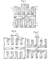
- Fig. 1 consists of two foil loop elements 1,2 located one(element 1) closely inside the other(element 2) and having complementary meander loop portions, also shown in Figs. 2 and 3, illustrating the configuration of each loop element 1,2.
- the different loop portions extend in different main directions, i.e. substantially perpendicular to each other.
- the metal foil is made of a rust-proof plate material having a thickness of about 35 ⁇ m.
- the metal foil is enclosed at both sides by polyester plastic which is punched simultaneously in one operation by means of a punch tool formed in correspondance to the configuration shown in Fig. 1.
- the metal foil may have a thickness of 20-100 um. If three loop elements are punched out at the same time, the thickness should be larger than the thickness of only two coil members, e.g. about 50 ⁇ m.
- the punched out loop elements are shortcircuited by a metal connection C1 (Fig. 2) and C2 (Fig.3), respectively.
- the purpose of this connection is to make the element stable enough during the assembly of the connection cables and an outer casing, e.g. in the form of a plastic net. Thereafter, the connection is cut away.
- one of the plastic foils e.g. the lower one, may have larger dimensions than the metal foil and the other plastic foil, so that a protruding plastic foil portion (not to be punched) constitutes the desired connection, which provides the member with the necessary stability during assembly.
- the form of the loop may vary at wish in view of the intended use.
- the meander loops may extend in mutually oblique main directions or in only one main direction.
- the loop elements do not necessarily have to be meander-shaped, but may have any, preferably closed configuration.
- the essential feature is that the loop elements are situated complementarily one inside the other and together cover the major part of the surface area in question so as to reduce the waste of material.
Abstract
Description
- The present invention relates to a method of manufacturing loop-formed metal foil elements intended to serve as electrical resistance heating elements.
- Such metal foil elements are known, e.g., from SE-A-7713250-4, and are being used more and more for various heating purposes, e.g. for heating car seats or other flexible surface elements, or for heating rigid surfaces, possibly having a complicated geometrical, in particular curved shape. For such purposes, it is usually essential that the loop-formed metal foil element covers a relatively large surface area, although for one reason or another the mutually adjacent parts of the loop element should preferably be well separated from each other, e.g. to enable stretching during assembly or use of the element.
- The manufacture of such loop elements with relatively sparsely distributed loop portions has hitherto involved a great waste of material, since the material between the loop portions was discarded. Moreover, conventional methods of printing and etching of loop patterns are extremely complicated and cumbersome.
- The object of the invention is to achieve a manufacturing method in which the waste of material is considerably reduced and, moreover, permitting an especially simple method, namely punching.
- Starting from a unitary metal foil, this object is achieved by simultaneously forming, particularly by punching, at least two complementarily extending loop elements, one inside the other. In this connection, it has rather surprisingly turned out that the difference in length, and thus in resistance, of two adjacent meander-shaped loop elements of the same width only amounts to a few percent, and such loop elements can therefore be used for the same purpose, e.g. in car seats.
- In practice, two or three loop elements, located one inside the other, can be formed at the same time, but in principle, even four or more loop elements may be produced. Already in case of two complementary elements, the material can be used up to about 70-80%, which means a considerable economic saving compared to conventional manufacturing methods. Moreover, the waste obtained when forming by punching is more favourable for re-use than by etching.
- Thus, the loop elements located inside each other will be approximately equal in length. If so desired, the actual differences in length, which are small, may be compensated by making the shorter loop elements somewhat narrower so that the resistance becomes equal.
- From the point of view of productivity, it is advantageous to punch a laminate consisting of the metal foil itself and two cover foils of thermoplastic material, e.g. polyester, on each side thereof, the two cover foils being stretched over the edges of the metal foil loop elements and being joined along these edges under the influence of heat, so that the metal foil loop elements are entirely closed by the cover foils. The joining can possible be effected during the punching operation by an adjusted design and heating of the punching tools.
- Suitably, the punching is performed by means of stamp and die, but principally, even a cutting punch can be used. A possible alternative to the punching operation is conventional production by etching the loop elements located inside each other. In such a case, a metal foil is applied to a supporting layer, preferably of thermoplastic material, such as polyester, and after etching the complementary loop elements a cover layer may be applied. Thereafter, the loop elements are punched out together with the metal foil loops enclosed between the enclosing layers.
- The invention will be described further below with reference to the appended drawing, which illustrates a simple embodiment.
- Fig. 1 shows in a planar view two foil loops, one inside the other, which have been punched out from a unitary foil laminate; and
- Figs. 2 and 3 show each of the two loop elements separately.
- The embodiment illustrated in Fig. 1 consists of two
foil loop elements loop element - With such an arrangement, it has turned out that the difference in resistance between the
elements - In the example the metal foil is made of a rust-proof plate material having a thickness of about 35 µm. The metal foil is enclosed at both sides by polyester plastic which is punched simultaneously in one operation by means of a punch tool formed in correspondance to the configuration shown in Fig. 1.
- In general, the metal foil may have a thickness of 20-100 um. If three loop elements are punched out at the same time, the thickness should be larger than the thickness of only two coil members, e.g. about 50 µm.
- In the embodiment the punched out loop elements are shortcircuited by a metal connection C1 (Fig. 2) and C2 (Fig.3), respectively. The purpose of this connection is to make the element stable enough during the assembly of the connection cables and an outer casing, e.g. in the form of a plastic net. Thereafter, the connection is cut away. As an alternative to such metal connections, one of the plastic foils, e.g. the lower one, may have larger dimensions than the metal foil and the other plastic foil, so that a protruding plastic foil portion (not to be punched) constitutes the desired connection, which provides the member with the necessary stability during assembly.
- Of course, the form of the loop may vary at wish in view of the intended use. Thus, the meander loops may extend in mutually oblique main directions or in only one main direction. The loop elements do not necessarily have to be meander-shaped, but may have any, preferably closed configuration. The essential feature is that the loop elements are situated complementarily one inside the other and together cover the major part of the surface area in question so as to reduce the waste of material.
Claims (6)
Applications Claiming Priority (2)
| Application Number | Priority Date | Filing Date | Title |
|---|---|---|---|
| SE8404231A SE8404231L (en) | 1984-08-24 | 1984-08-24 | SET TO MAKE SLEEPING METAL FILM ELEMENTS |
| SE8404231 | 1984-08-24 |
Publications (2)
| Publication Number | Publication Date |
|---|---|
| EP0175662A1 true EP0175662A1 (en) | 1986-03-26 |
| EP0175662B1 EP0175662B1 (en) | 1990-07-11 |
Family
ID=20356794
Family Applications (1)
| Application Number | Title | Priority Date | Filing Date |
|---|---|---|---|
| EP85850249A Expired - Lifetime EP0175662B1 (en) | 1984-08-24 | 1985-07-26 | Method of manufacturing loop-formed metal foil elements |
Country Status (6)
| Country | Link |
|---|---|
| US (1) | US4642887A (en) |
| EP (1) | EP0175662B1 (en) |
| JP (1) | JPS61108429A (en) |
| DE (1) | DE3578627D1 (en) |
| ES (1) | ES8705180A1 (en) |
| SE (1) | SE8404231L (en) |
Cited By (4)
| Publication number | Priority date | Publication date | Assignee | Title |
|---|---|---|---|---|
| FR2678466A1 (en) * | 1991-06-27 | 1992-12-31 | Navarra Componentes Electronic | Heating device employing contact heat transfer |
| WO2004002806A1 (en) * | 2002-06-28 | 2004-01-08 | W.E.T. Automotive Systems Ag | Steering wheel with electrical heating element |
| EP2845764A1 (en) * | 2013-09-05 | 2015-03-11 | ALT Technologies B.V. | Flexible laminate |
| CN108712790A (en) * | 2018-04-08 | 2018-10-26 | 佛山市瑞福物联科技有限公司 | A kind of circuit arrangement method |
Families Citing this family (8)
| Publication number | Priority date | Publication date | Assignee | Title |
|---|---|---|---|---|
| SE8505911L (en) * | 1985-12-13 | 1987-06-14 | Kanthal Ab | Foil elements |
| US5783743A (en) * | 1995-07-08 | 1998-07-21 | Vdo Adolf Schindling Ag | Moisture sensor |
| DE19524943C2 (en) * | 1995-07-08 | 2003-05-08 | Siemens Ag | sensor |
| DE19638640C2 (en) * | 1996-09-21 | 2000-11-30 | Diehl Ako Stiftung Gmbh & Co | Radiant heater with a metal foil heating conductor |
| DE10126134B4 (en) * | 2001-05-29 | 2004-02-26 | W.E.T. Automotive Systems Ag | Flat heating element |
| US8544942B2 (en) * | 2010-05-27 | 2013-10-01 | W.E.T. Automotive Systems, Ltd. | Heater for an automotive vehicle and method of forming same |
| LU101364B1 (en) | 2019-08-22 | 2021-03-05 | Iee Sa | Hybrid Printed Heater with Optional PTC Effect |
| CN113611468A (en) * | 2021-07-26 | 2021-11-05 | 电子科技大学 | Method for manufacturing resistive film and micro-area hot plate |
Citations (9)
| Publication number | Priority date | Publication date | Assignee | Title |
|---|---|---|---|---|
| GB912980A (en) * | 1958-01-13 | 1962-12-12 | Eisler Paul | Production of laminates embodying electrically conductive patterns |
| US3495328A (en) * | 1967-07-07 | 1970-02-17 | Corning Glass Works | Electric heating unit |
| US4002883A (en) * | 1975-07-23 | 1977-01-11 | General Electric Company | Glass-ceramic plate with multiple coil film heaters |
| DE2615064A1 (en) * | 1976-04-07 | 1977-10-20 | Husqvarna Ab | COOKING PAN WITH ELECTRONICALLY CONTROLLED TEMPERATURE REGULATION AND A PROCESS FOR MANUFACTURING THE SAME |
| US4057707A (en) * | 1975-10-17 | 1977-11-08 | Corning Glass Works | Electric heating unit |
| US4063068A (en) * | 1976-08-12 | 1977-12-13 | Minnesota Mining And Manufacturing Company | Food heating and cooking receptacle |
| EP0024319A1 (en) * | 1979-08-21 | 1981-03-04 | Schwabe GmbH & Co. KG Elektrotechnische Fabrik | Process for making E-shaped core laminations and I-shaped yoke laminations for a choke or transformer, particularly for gas discharge lamps |
| EP0028494A1 (en) * | 1979-11-02 | 1981-05-13 | Linton And Hirst Limited | Method for forming laminations for transformer cores |
| US4378489A (en) * | 1981-05-18 | 1983-03-29 | Honeywell Inc. | Miniature thin film infrared calibration source |
Family Cites Families (4)
| Publication number | Priority date | Publication date | Assignee | Title |
|---|---|---|---|---|
| US1498969A (en) * | 1920-01-03 | 1924-06-24 | William H Keller | Manufacture of resistance grids |
| US1606282A (en) * | 1924-10-29 | 1926-11-09 | Claude A Witter | Process of making pipe flanges |
| FR2141562B1 (en) * | 1971-06-16 | 1974-03-08 | Cebal Gp | |
| SE8205712L (en) * | 1982-10-06 | 1984-04-07 | Bulten Kanthal Ab | HEATING DEVICE AND WAY TO MANUFACTURE THEM |
-
1984
- 1984-08-24 SE SE8404231A patent/SE8404231L/en unknown
-
1985
- 1985-07-26 EP EP85850249A patent/EP0175662B1/en not_active Expired - Lifetime
- 1985-07-26 DE DE8585850249T patent/DE3578627D1/en not_active Expired - Lifetime
- 1985-08-15 JP JP60180024A patent/JPS61108429A/en active Pending
- 1985-08-21 ES ES546310A patent/ES8705180A1/en not_active Expired
- 1985-08-23 US US06/768,592 patent/US4642887A/en not_active Expired - Fee Related
Patent Citations (9)
| Publication number | Priority date | Publication date | Assignee | Title |
|---|---|---|---|---|
| GB912980A (en) * | 1958-01-13 | 1962-12-12 | Eisler Paul | Production of laminates embodying electrically conductive patterns |
| US3495328A (en) * | 1967-07-07 | 1970-02-17 | Corning Glass Works | Electric heating unit |
| US4002883A (en) * | 1975-07-23 | 1977-01-11 | General Electric Company | Glass-ceramic plate with multiple coil film heaters |
| US4057707A (en) * | 1975-10-17 | 1977-11-08 | Corning Glass Works | Electric heating unit |
| DE2615064A1 (en) * | 1976-04-07 | 1977-10-20 | Husqvarna Ab | COOKING PAN WITH ELECTRONICALLY CONTROLLED TEMPERATURE REGULATION AND A PROCESS FOR MANUFACTURING THE SAME |
| US4063068A (en) * | 1976-08-12 | 1977-12-13 | Minnesota Mining And Manufacturing Company | Food heating and cooking receptacle |
| EP0024319A1 (en) * | 1979-08-21 | 1981-03-04 | Schwabe GmbH & Co. KG Elektrotechnische Fabrik | Process for making E-shaped core laminations and I-shaped yoke laminations for a choke or transformer, particularly for gas discharge lamps |
| EP0028494A1 (en) * | 1979-11-02 | 1981-05-13 | Linton And Hirst Limited | Method for forming laminations for transformer cores |
| US4378489A (en) * | 1981-05-18 | 1983-03-29 | Honeywell Inc. | Miniature thin film infrared calibration source |
Cited By (6)
| Publication number | Priority date | Publication date | Assignee | Title |
|---|---|---|---|---|
| FR2678466A1 (en) * | 1991-06-27 | 1992-12-31 | Navarra Componentes Electronic | Heating device employing contact heat transfer |
| WO2004002806A1 (en) * | 2002-06-28 | 2004-01-08 | W.E.T. Automotive Systems Ag | Steering wheel with electrical heating element |
| EP2845764A1 (en) * | 2013-09-05 | 2015-03-11 | ALT Technologies B.V. | Flexible laminate |
| US9769918B2 (en) | 2013-09-05 | 2017-09-19 | Alt Technologies B.V. | Flexible laminate |
| CN108712790A (en) * | 2018-04-08 | 2018-10-26 | 佛山市瑞福物联科技有限公司 | A kind of circuit arrangement method |
| CN108712790B (en) * | 2018-04-08 | 2021-04-06 | 佛山市瑞福物联科技有限公司 | Circuit arrangement method |
Also Published As
| Publication number | Publication date |
|---|---|
| EP0175662B1 (en) | 1990-07-11 |
| SE8404231L (en) | 1986-02-25 |
| US4642887A (en) | 1987-02-17 |
| ES546310A0 (en) | 1987-04-16 |
| SE8404231D0 (en) | 1984-08-24 |
| ES8705180A1 (en) | 1987-04-16 |
| JPS61108429A (en) | 1986-05-27 |
| DE3578627D1 (en) | 1990-08-16 |
Similar Documents
| Publication | Publication Date | Title |
|---|---|---|
| EP0175662A1 (en) | Method of manufacturing loop-formed metal foil elements | |
| EP0581588B1 (en) | Metal plane support for a multi-layer lead frame and a process for manufacturing it | |
| US4437074A (en) | Ultrahigh-frequency transmission line of the three-plate air type and uses thereof | |
| US4255644A (en) | Micro-soldering tool | |
| US9667016B2 (en) | Connecting blade, method of producing connecting blade, and electrical connector including connecting blade | |
| US5100498A (en) | Method of producing a minutely patterned structure | |
| EP0147807A2 (en) | Method for forming a substrate for tape automated bonding for electronic circuit elements | |
| KR980006719A (en) | Stator iron core member and manufacturing method of stator iron core using same, Stator iron core member and stator iron core using same | |
| JP3236660U (en) | Alloy resistant serial array type alloy sheet structure | |
| EP1119225A2 (en) | Circuit board, electrical connection box having the circuit board and method of making the circuit board | |
| WO2004085090A1 (en) | A bush and method of manufacturing a bush | |
| GB2157200A (en) | Method of making electrical contacts | |
| JP3245231B2 (en) | Manufacturing method of flat cable circuit | |
| EP0295910B1 (en) | Integrated cutting blade assembly | |
| CA1111145A (en) | Method of making printed circuit | |
| JP2847246B2 (en) | Flexible circuit board assembly and method of manufacturing the same | |
| US5005455A (en) | Method and apparatus for manufacturing preform panels with preforms for repairing interconnects | |
| CZ300870B6 (en) | Process for producing insulation bundle for insulation part, insulating bundle processed with this method and dividing tool for performing this method | |
| JPS60159034A (en) | Manufacture of emblem mark | |
| JPS6147917B2 (en) | ||
| US6585024B1 (en) | Positioning target for laminated printed circuit board | |
| JP2001160501A (en) | Laminate and method of manufacturing electronic part by use thereof | |
| JPS603509Y2 (en) | sheet heating element | |
| KR950008388B1 (en) | Manufacturing method of stator core for the generator | |
| JP2502338B2 (en) | Reciprocating razor outer blade body |
Legal Events
| Date | Code | Title | Description |
|---|---|---|---|
| PUAI | Public reference made under article 153(3) epc to a published international application that has entered the european phase |
Free format text: ORIGINAL CODE: 0009012 |
|
| AK | Designated contracting states |
Kind code of ref document: A1 Designated state(s): DE FR GB IT SE |
|
| 17P | Request for examination filed |
Effective date: 19860919 |
|
| 17Q | First examination report despatched |
Effective date: 19880804 |
|
| GRAA | (expected) grant |
Free format text: ORIGINAL CODE: 0009210 |
|
| AK | Designated contracting states |
Kind code of ref document: B1 Designated state(s): DE FR GB IT SE |
|
| ITF | It: translation for a ep patent filed |
Owner name: STUDIO TORTA SOCIETA' SEMPLICE |
|
| PGFP | Annual fee paid to national office [announced via postgrant information from national office to epo] |
Ref country code: GB Payment date: 19900720 Year of fee payment: 6 |
|
| PGFP | Annual fee paid to national office [announced via postgrant information from national office to epo] |
Ref country code: FR Payment date: 19900725 Year of fee payment: 6 |
|
| ITTA | It: last paid annual fee | ||
| REF | Corresponds to: |
Ref document number: 3578627 Country of ref document: DE Date of ref document: 19900816 |
|
| ET | Fr: translation filed | ||
| PGFP | Annual fee paid to national office [announced via postgrant information from national office to epo] |
Ref country code: DE Payment date: 19900820 Year of fee payment: 6 |
|
| PGFP | Annual fee paid to national office [announced via postgrant information from national office to epo] |
Ref country code: SE Payment date: 19900907 Year of fee payment: 6 |
|
| PLBE | No opposition filed within time limit |
Free format text: ORIGINAL CODE: 0009261 |
|
| STAA | Information on the status of an ep patent application or granted ep patent |
Free format text: STATUS: NO OPPOSITION FILED WITHIN TIME LIMIT |
|
| 26N | No opposition filed | ||
| PG25 | Lapsed in a contracting state [announced via postgrant information from national office to epo] |
Ref country code: GB Effective date: 19910726 |
|
| PG25 | Lapsed in a contracting state [announced via postgrant information from national office to epo] |
Ref country code: SE Effective date: 19910727 |
|
| GBPC | Gb: european patent ceased through non-payment of renewal fee | ||
| PG25 | Lapsed in a contracting state [announced via postgrant information from national office to epo] |
Ref country code: FR Effective date: 19920331 |
|
| PG25 | Lapsed in a contracting state [announced via postgrant information from national office to epo] |
Ref country code: DE Effective date: 19920401 |
|
| REG | Reference to a national code |
Ref country code: FR Ref legal event code: ST |
|
| EUG | Se: european patent has lapsed |
Ref document number: 85850249.5 Effective date: 19920210 |