EP0173876A1 - Verfahren und Vorrichtung zur Reinigung, Desinfektion und Sterilisation von ärztlichen, insbesondere zahnärztlichen Instrumenten - Google Patents
Verfahren und Vorrichtung zur Reinigung, Desinfektion und Sterilisation von ärztlichen, insbesondere zahnärztlichen Instrumenten Download PDFInfo
- Publication number
- EP0173876A1 EP0173876A1 EP85109941A EP85109941A EP0173876A1 EP 0173876 A1 EP0173876 A1 EP 0173876A1 EP 85109941 A EP85109941 A EP 85109941A EP 85109941 A EP85109941 A EP 85109941A EP 0173876 A1 EP0173876 A1 EP 0173876A1
- Authority
- EP
- European Patent Office
- Prior art keywords
- container
- liquid
- electrolytic cell
- cleaning
- instruments
- Prior art date
- Legal status (The legal status is an assumption and is not a legal conclusion. Google has not performed a legal analysis and makes no representation as to the accuracy of the status listed.)
- Granted
Links
Images


Classifications
-
- A—HUMAN NECESSITIES
- A61—MEDICAL OR VETERINARY SCIENCE; HYGIENE
- A61L—METHODS OR APPARATUS FOR STERILISING MATERIALS OR OBJECTS IN GENERAL; DISINFECTION, STERILISATION OR DEODORISATION OF AIR; CHEMICAL ASPECTS OF BANDAGES, DRESSINGS, ABSORBENT PADS OR SURGICAL ARTICLES; MATERIALS FOR BANDAGES, DRESSINGS, ABSORBENT PADS OR SURGICAL ARTICLES
- A61L2/00—Methods or apparatus for disinfecting or sterilising materials or objects other than foodstuffs or contact lenses; Accessories therefor
- A61L2/02—Methods or apparatus for disinfecting or sterilising materials or objects other than foodstuffs or contact lenses; Accessories therefor using physical phenomena
- A61L2/03—Electric current
- A61L2/035—Electrolysis
-
- A—HUMAN NECESSITIES
- A61—MEDICAL OR VETERINARY SCIENCE; HYGIENE
- A61L—METHODS OR APPARATUS FOR STERILISING MATERIALS OR OBJECTS IN GENERAL; DISINFECTION, STERILISATION OR DEODORISATION OF AIR; CHEMICAL ASPECTS OF BANDAGES, DRESSINGS, ABSORBENT PADS OR SURGICAL ARTICLES; MATERIALS FOR BANDAGES, DRESSINGS, ABSORBENT PADS OR SURGICAL ARTICLES
- A61L2/00—Methods or apparatus for disinfecting or sterilising materials or objects other than foodstuffs or contact lenses; Accessories therefor
- A61L2/02—Methods or apparatus for disinfecting or sterilising materials or objects other than foodstuffs or contact lenses; Accessories therefor using physical phenomena
- A61L2/025—Ultrasonics
-
- A—HUMAN NECESSITIES
- A61—MEDICAL OR VETERINARY SCIENCE; HYGIENE
- A61L—METHODS OR APPARATUS FOR STERILISING MATERIALS OR OBJECTS IN GENERAL; DISINFECTION, STERILISATION OR DEODORISATION OF AIR; CHEMICAL ASPECTS OF BANDAGES, DRESSINGS, ABSORBENT PADS OR SURGICAL ARTICLES; MATERIALS FOR BANDAGES, DRESSINGS, ABSORBENT PADS OR SURGICAL ARTICLES
- A61L2/00—Methods or apparatus for disinfecting or sterilising materials or objects other than foodstuffs or contact lenses; Accessories therefor
- A61L2/24—Apparatus using programmed or automatic operation
-
- C—CHEMISTRY; METALLURGY
- C02—TREATMENT OF WATER, WASTE WATER, SEWAGE, OR SLUDGE
- C02F—TREATMENT OF WATER, WASTE WATER, SEWAGE, OR SLUDGE
- C02F1/00—Treatment of water, waste water, or sewage
- C02F1/34—Treatment of water, waste water, or sewage with mechanical oscillations
- C02F1/36—Treatment of water, waste water, or sewage with mechanical oscillations ultrasonic vibrations
-
- C—CHEMISTRY; METALLURGY
- C02—TREATMENT OF WATER, WASTE WATER, SEWAGE, OR SLUDGE
- C02F—TREATMENT OF WATER, WASTE WATER, SEWAGE, OR SLUDGE
- C02F1/00—Treatment of water, waste water, or sewage
- C02F1/46—Treatment of water, waste water, or sewage by electrochemical methods
- C02F1/461—Treatment of water, waste water, or sewage by electrochemical methods by electrolysis
- C02F1/46104—Devices therefor; Their operating or servicing
-
- C—CHEMISTRY; METALLURGY
- C02—TREATMENT OF WATER, WASTE WATER, SEWAGE, OR SLUDGE
- C02F—TREATMENT OF WATER, WASTE WATER, SEWAGE, OR SLUDGE
- C02F1/00—Treatment of water, waste water, or sewage
- C02F1/46—Treatment of water, waste water, or sewage by electrochemical methods
- C02F1/461—Treatment of water, waste water, or sewage by electrochemical methods by electrolysis
- C02F1/467—Treatment of water, waste water, or sewage by electrochemical methods by electrolysis by electrochemical disinfection; by electrooxydation or by electroreduction
- C02F1/4672—Treatment of water, waste water, or sewage by electrochemical methods by electrolysis by electrochemical disinfection; by electrooxydation or by electroreduction by electrooxydation
- C02F1/4674—Treatment of water, waste water, or sewage by electrochemical methods by electrolysis by electrochemical disinfection; by electrooxydation or by electroreduction by electrooxydation with halogen or compound of halogens, e.g. chlorine, bromine
Definitions
- the instruments used in medical or dental treatment should be sterile.
- the invention specified in claims 1 and 7 is based on the object of avoiding the disadvantages of the known methods and of specifying a method and a device with which the instruments in relatively short time from a hygienic point of view, it can still be cleaned and sterilized in a way that is gentle on the instruments and the environment.
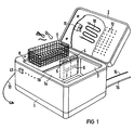
- FIG. 1 shows, in a diagrammatic representation, a device operating according to the method described in more detail below.
- a box-shaped housing 1 which is divided into two adjacent housing sections 1 a, 1 b, which can be sealed off by means of a hinge-like cover 2, contains a trough-like container 3 in housing section 1 a. as well as another container 5 for receiving a mixture of sodium chloride (NaCl) and a surfactant.
- the two containers 4, 5 are connected to the tub 3 through openings 6, 7.
- Various electrical and hydraulic components shown in FIGS. 2 and 4 and an electrolytic cell shown in more detail in FIG. 3 are also accommodated in the housing section 1b.
- the housing section 1b forms a shelf 8 on the top side, on which a wire basket 9 can be placed, into which the instruments 10 to be cleaned and sterilized (scissors, tweezers, drilling tools, etc.) are inserted.
- a heating coil 10 e.g. infrared radiator
- a miniature fan 11 are accommodated in the cover 2, which is also box-shaped. By means of the fan 11, as will be explained later, air heated by the heating coil 10 can be guided into the trough 3 via openings 12 provided in the cover.
- the electrical supply of the electrical components takes place via a network connection 13. Fresh water is supplied via the line 14, and waste water is discharged via the line 15.
- FIG. 2 it is clear that in a lower housing section 1c immediately below the container 3 and mechanically coupled to the bottom of an ultrasonic vibrator 16 is attached in a known manner, via which the liquid filled in the container 3 can be acted upon by ultrasonic energy. Also arranged in the housing section 1c is a shaking device, designated 17, a movement unit which is also known per se and which serves to set the basket 9 inserted in the container into a shaking movement if required. In the container 3 there are also two level meters, e.g. in the form of electronic conductance probes, provided, an upper level meter 18 "and a lower level meter 19. 20 is a circulation pump, which, like solenoid valves V21 to V28 and an electrolytic cell designated 29, are housed in the housing section 1b.
- a circulation pump which, like solenoid valves V21 to V28 and an electrolytic cell designated 29, are housed in the housing section 1b.
- a housing 30 of rectangular cross section made of insulating material with the dimensions of approx. 150 x 100 x 30 mm forms a cavity 31, which is divided into an anolyte space 33 and a catholyte space 34 by a longitudinally clamped, ion-conducting membrane 32.
- the membrane preferably consists of sulfonated polytetrafluoroethylene and can be referred to as a cation exchange membrane.
- An anode 35 is arranged in the anolyte compartment 33 and a cathode 36 in the catholyte compartment 34.
- Anode and cathode are made of the same material, preferably activated titanium. They can also be made from platinum with or several dotted networks made of platinum or platinum and iridium. Instead of the nets, as shown in the embodiment according to FIGS. 5 and 6, expanded metals made of titanium or tantalum can also be used, which are coated with platinum black or platinum and ruthenium oxide. When using such electrodes, the separating membrane between the anode and cathode can be dispensed with.
- chlorine-resistant porous metals such as Raney platinum and porous titanium sponges, or sintered metals, which may be coated with noble metal catalysts, as the electrode material.
- a chemical-resistant fabric e.g. made of Teflon.
- the turbulence grid can be omitted. The necessary swirling of the water flowing through is already achieved through the geonetric structure of the expanded metal.
- the anolyte space 33 is connected to the catholyte space 34 via a channel 38, as a result of which the liquid flowing in in the direction of the arrow via the channel 39 can pass into the catholyte space after passing through the anolyte space and can exit again at the outlet channel 40 after it has flowed through it.
- FIGS. 5 and 6 Another advantageous embodiment of an electrolytic cell is shown in FIGS. 5 and 6.
- the outer shape of the cell and the electrode structure are essentially as in Figure 3, i.e.
- two electrodes 51, 52 that can be applied to direct voltage are arranged at a distance of 0.5 to 5 mm.
- inflow channel 54 and outflow channel 55 are arranged opposite one another.
- through-flow or venting channels 56 between electrodes and housing which, as can be seen from the sectional illustration in FIG. 6, are arranged in the through-flow direction.
- the channels can also be honeycomb-shaped; conceivable, and it is within the scope of the invention to also place the electrodes at a distance from the housing by other suitable measures. It is advantageous for an optimal flow rate to also provide a distribution space 57, 58 which extends across the width of the electrodes before and after the electrodes.
- Containers 4 and 5 are filled with a pre-metered amount of a powdery or liquid surfactant in one and a mixture of surfactant and sodium chloride in the other container, either by hand or via external metering dispensers, which can be attached in the vicinity of the apparatus. After closing the lid 2, the cleaning, disinfection and sterilization process can begin.
- a start button 41 After pressing a start button 41 (FIG. 1), fresh water is passed through the electrolyte cell 29 and through the surfactant container 4 into the container 3 via the supply line 14 and the opened valves 21, 22, 25 and -27. The water flow flushes the detergent in the surfactant container into the container. After reaching the necessary fill level, which is registered by the fill level meter 18, the water supply is interrupted by closing the valves 21 and 27. With the start command, the movement unit 17 is switched on at the same time. The movement unit sets the basket 9 and the instruments contained therein in a shaking movement, which can be a vertically or horizontally oscillating movement.
- the ultrasound oscillator 16 (FIG. 2) is set in vibration, as a result of which ultrasound energy is applied to the liquid in the container 3. This is where the rough cleaning begins. It has proven to be beneficial for the cleaning effect if the ultrasound frequency is below 35 kHz (approximately 30 kHz) and the HF power is at least 80 W / 1 bath content. The surfactant used should have a low foaming effect.
- the cleaning time required for the rough cleaning is approximately 3 to 5 minutes (T1). After switching off the ultrasonic electronics 42, the contents of the container 3 are pumped into the drain. For this purpose, the circulation pump 20 and the solenoid valve 26 are switched on.
- the container After the fine cleaning and sterilization, i.e. after switching off the ultrasound electronics 42 and the solenoid valve 28, the container is emptied into the drain and refilled from the mains in the same manner as described above.
- the contents of the container also run continuously with circulation through the electrolytic cell 29 switched on.
- the cell is now operated at a reduced current density of approximately 5 mA / cm 2 to 20 mA / cm 2 .
- This current density is sufficient to kill germs that may have been brought in by the mains water.
- the rinsing phase is therefore carried out with practically sterile liquid.
- T3 the contents of the container are again emptied into the drain by pumping.
- the entire process sequence can be controlled according to the basic circuit shown in FIG. 4, with control electronics 43, which can preferably be formed by a microprocessor, control the program sequence.
- the signals which are obtained from the fill level meters 18 and 19 serve as input variables. If electronic conductance probes are used as a level meter, one can not only derive the control of the level from the electrical conductance of the liquid, but also a check whether the amounts of surfactant or sodium chloride required for cleaning are available.
- the surfactant and sodium chloride dosage can also be determined from the cell voltage electrolytic cell 29 and the cell current can be derived.
- the electrolytic cell 29 receives its voltage from control electronics designated 44 and switched on via switch S44.
- a relay 48 interrupts the ongoing process and does e.g. an acoustic signal alerts you to functional and operating errors.
- the contacts S22, S45 and S46 are switched by means of a relay 49.
- Relay 49 can be attracted to odd-numbered program sequences, and can be in the rest position with even-numbered program sequences.
- This changeover reverses the flow direction through the cell 29 (by means of valves 23, 24) and on the other hand changes the polarity of the electrodes 35, 36 (by means of changeover contacts S45, S46).
- the inflowing liquid first comes into contact with the anode, even if the polarity is reversed and the flow direction is reversed, the inflowing liquid will first be in contact with the anode.
- the detergent and sodium chloride can be added from larger storage containers via a metering device.
- the electrical structure can also be further simplified; the number of solenoid valves V22, V23, V24 and V25 for switching the flow direction of the electrolytic cell can be reduced by using four two-way valves.
Abstract
Description
- Aus hygienischer Sicht sollen die bei ärztlicher bzw. zahnärztlicher Behandlung benutzten Instrumente, wie Zangen, Pinzetten, Bohrwerkzeuge etc., keimfrei sein. Um diese Forderung zu erfüllen, ist es in der Praxis üblich,die Instrumente nach Gebrauch mittels Ultraschallreinigungsanlagen (US-30 07 478 und 36 40 295) zu reinigen und in weiteren Arbeitsgängen zu desinfizieren bzw. zu sterilisieren. Die Desinfektion wird in der Regel mit chemischen Mitteln (Alkoholen, Phenolen) durchgeführt, während zur Sterilisation Heißluft von etwa 180 bis 200°C oder gespannter Heißdampf Verwendung finden.
- Insbesondere Instrumente (oder auch Teile davon) aus nichtmetallischen Werkstoffen halten diesen relativ hohen thermischen Beanspruchungen beim Sterilisieren nicht stand. Um auch derartig empfindliche Instrumente schonend zu sterilisieren, sind sogenannte Gassterilisatoren auf der Basis von Äthylenoxid im Einsatz. Nachteilig bei dieser Methode sind die relativ lange Sterilisationszeit von einigen Stunden und, weil Äthylenoxid stark toxisch und feuergefährlich ist, der damit verbundene, relativ hohe sicherheitstechnische Aufwand.
- Der in den Ansprüchen 1 und 7 angegebenen Erfindung liegt die Aufgabe zugrunde, die Nachteile der bekannten Methoden zu vermeiden und ein Verfahren und eine Vorrichtung anzugeben, mit der die Instrumente in relativ kurzer Zeit aus hygienischer Sicht einwandfrei, dennoch aber instrumenten- und umweltschonend gereinigt und gleichsam sterilisiert werden können.
- Ein wesentlicher Vorzug der vorgeschlagenen Maßnahmen ist, daß die mit Keimen kontaminierten Instrumente nun nicht mehr in mehreren Arbeitsgängen zunächst desinfiziert (um eine Infektion des Bedienpersonals zu verhindern), anschließend manuell oder in einer Waschmaschine gereinigt und schließlich in einem weiteren Arbeitsgang sterilisiert werden müssen. Gemäß der Erfindung können diese Schritte nunmehr selbsttätig in einer einzigen Apparatur in folgender Reihenfolge durchgeführt werden:
- 1. Grobreinigung in einem Ultraschallbad.
- 2. Feinreinigung und Sterilisation im Ultraschallbad unter Umwälzung der Flüssigkeit über eine elektrolytische Zelle.
- 3. Spülen mit Sterilflüssigkeit im Ultraschallbad.
- 4. Trocknen mittels steriler Warmluft.
- Nachfolgend wird das Verfahren sowie eine Vorrichtung nach diesem Verfahren näher beschrieben. Es zeigen:
- Figur 1 die erfindungsgemäße Vorrichtung in einer schaubildlichen Darstellung,
- Figur 2 eine Prinzipskizze der Vorrichtung nach Figur 1 mit der zugehörigen hydraulischen Schaltung,
- Figur 3 einen Längsschnitt durch die in Figur 2 schematisch dargestellte elektrolytische Zelle,
- Figur 4 eine Prinzipschaltung der gesamten Anlage,
- Figuren 5 und 6 eine weitere Ausführungsform einer elektrolytischen Zelle.
- Die Figur 1 zeigt in einer schaubildlichen Darstellung eine nach dem nachfolgend noch näher beschriebenen Verfahren arbeitende Vorrichtung. Ein kastenförmig ausgebildetes, in zwei nebeneinanderliegende Gehäuseabschnitte la, ib unterteiltes Gehäuse 1, welches mittels eines scharnierartig befestigten Deckels 2 dicht abgeschlossen werden kann, enthält im Gehäuseabschnitt 1a einen wannenartigen Behälter 3. Im Gehäuseabschnitt 1b ist ein Behälter 4 zur Aufnahme eines Reinigungsmittels (Tensid) sowie ein weiterer Behälter 5 zur Aufnahme eines Gemisches aus Natriumchlorid (NaCl) und eines Tensides untergebracht. Die beiden Behälter 4, 5 sind durch Öffnungen 6, 7 mit der Wanne 3 verbunden. Im Gehäuseabschnitt 1b sind weiterhin noch diverse, in Figur 2 und 4 aufgezeigte elektrische und hydraulische Bauteile sowie eine in Figur 3 näher dargestellte elektrolytische Zelle untergebracht. Der Gehäuseabschnitt 1b bildet deckseitig eine Ablage 8, auf der ein Drahtkorb 9 abgestellt werden kann, in den die zu reinigenden und zu sterilisierenden Instrumente 10 (Scheren, Pinzetten, Bohrwerkzeuge etc.) eingelegt werden. In den ebenfalls kastenförmig ausgebildeten Deckel 2 sind eine Heizspirale 10 (z.B. Infrarotstrahler) sowie ein Miniaturlüfter 11 untergebracht. Mittels des Lüfters 11 kann, wie später noch erläutert, von der Heizspirale 10 erwärmte Luft über im Deckel vorgesehene Öffnungen 12 in die Wanne 3 geleitet werden. Die elektrische Versorgung der elektrischen Bauteile erfolgt über einen Netzanschluß 13. Mittels der Leitung 14 wird Frischwasser zugeführt, mittels der Leitung 15 Abwasser abgeführt.
- In Betrachtung von Figur 2 wird deutlich, daß in einem unteren Gehäuseabschnitt 1c unmittelbar unterhalb des Behälters 3 und mit dessen Boden mechanisch gekoppelt ein in bekannter Weise aufgebauter Ultraschallschwinger 16 befestigt ist, über den die im Behälter 3 eingefüllte Flüssigkeit mit Ultraschallenergie beaufschlagt werden kann. Im Gehäuseabschnitt 1c ist ferner noch eine mit 17 bezeichnete Rütteleinrichtung angeordnet, ein an sich ebenfalls bekanntes Bewegungsaggregat, welches dazu dient, den in den Behälter eingesetzten Korb 9 bei Bedarf in eine Rüttelbewegung zu versetzen. Im Behälter 3 sind ferner zwei Füllstandsmesser, z.B. in Form von elektronischen Leitwertsonden, vorgesehen, Ein oberer Füllstandsmesser 18 " und ein unterer Füllstandsmesser 19. Mit 20 ist eine Umwälzpumpe bezeichnet, die, ebenso wie Magnetventile V21 bis V28 und eine mit 29 bezeichnete elektrolytische Zelle, im Gehäuseabschnitt 1b untergebracht sind.
- Der Aufbau der elektrolytischen Zelle 29 wird anhand der Figuren 3, 5 und 6 näher erläutert. Bei der Zelle gemäß Figur 3 bildet ein im Querschnitt rechteckiges Gehäuse 30aus Isoliermaterial mit den Maßen von ca. 150 x 100 x 30 mm einen Hohlraum 31, welcher durch eine längs eingespannte, ionenleitende Membran 32 in einen Anolytraum 33 und einen Katholytraum 34 unterteilt ist. Die Membran besteht vorzugsweise aus sulfoniertem Polytetrafluoräthylen und kann als Kationenaustauschermembran bezeichnet werden. Im Anolytraum 33 ist eine Anode 35, im Katholytraum 34 eine Kathode 36 angeordnet. Anode und Kathode bestehen aus gleichem Material, vorzugsweise aus aktiviertem Titan. Sie können auch aus Platinblech mit einem oder mehreren aufgepunkteten Netzen aus Platin oder aus Platin und Iridium bestehen. Anstelle der Netze können, wie in der Ausführung gemäß Figuren 5 und 6 gezeigt, auch Streckmetalle aus Titan oder Tantal eingesetzt werden, die mit Platinmohr oder Platin-und Rutheniumoxid belegt sind. Bei Anwendung solcher Elektroden kann auf die Trennmembran zwischen Anode und Kathode verzichtet werden.
- Vorteilhaft ist es auch, gegen Chlor beständige poröse Metalle, wie Raney-Platin und porösen Titanschwann, oder gesinterte Metalle, die gegebenenfalls mit Edelmetallkatlaysatoren belegt sind, als Elektrodenmaterial einzusetzen.
- Mit 37 ist ein Turbulenzgitter bezeichnet, welches in den beiden Räumen 33, 34 eingebracht ist und dazu dienen soll, die Wasserströmung in einen Turbulenzzustand zu versetzen. Als Material ist zweckmäßigerweise ein chemikalienbeständiges Gewebe, z.B. aus Teflon, vorgesehen. Bei Verwendung von Streckmetall-Elektroden, wie in Figuren 5 und 6 gezeigt, kann das Turbulenzgitter entfallen. Die notwendige Verwirbelung des durchfließenden Wassers wird bereits durch den geonetrischen Aufbau des Streckmetalles erreicht.
- Der Anolytraum 33 ist über einen Kanal 38 mit dem Katholytraum 34 verbunden, wodurch die in Pfeilrichtung über den Kanal 39 einströmende Flüssigkeit nach Durchgang durch den Anolytraum in den Katholytraum übertreten und nach dessen Durchströmen an Auslaßkanal 40 wieder austreten kann.
- Eine andere vorteilhafte Ausführungsform einer elektrolytischen Zelle ist in den Figuren 5 und 6 dargestellt. Die äußere Form der Zelle und der Elektrodenaufbau sind im wesentlichen wie in Figur 3, d.h. in einem Gehäuse 50 aus Isoliermaterial sind in einen Abstand von 0,5 bis 5 mm zwei an Gleichspannung anlegbare Elektroden 51, 52 angeordnet. Im Gegensatz zu der zuvor beschriebenen Ausführung ist jedoch keine Membran vorhanden, die den Hohl- bzw. Durchflußraum 53 unterteilen würde. Demgemäß sind Zuflußkanal 54 und AbfluBkanal 55 einander gegenüberstehend angeordnet. Um einen gleiehmäßigeren Durchfluß der Flüssigkeit durch die Zelle zu bekommen, ist es zweckmäßig, wie gestrichelt eingezeichnet, mehrere Zu- und Abflußkanäle 54a, 55a vorzusehen. Zur Verbesserung des Wirkungsgrades ist es außerdem vorteilhaft, zwischen Elektroden und Gehäuse Durchflutungs- bzw. Entlüftungskanäle 56 vorzusehen, die, wie aus der Schnittdarstellung in Figur 6 ersichtlich, in Durchflußrichtung angeordnet sind. Die Kanäle können ebenso wabenförmig ausgebildet sein; denkbar, und im Rahmen der Erfindung liegt es, auch, die Elektroden gegenüber dem Gehäuse durch andere geeignete Maßnahmen auf Abstand zu setzen. Vorteilhaft für einen optimalen Durchfluß ist es, außerdem vor und nach den Elektroden einen über die Breite der Elektroden sich erstreckenden Verteilerraum 57, 58 vorzusehen.
- Wenngleich zwar der Wirkungsgrad der zuletzt beschriebenen Einkammer-Zelle nicht so gut ist, wie der der zuerst beschriebenen Zweikammer-Zelle, so ist doch der Aufbau der Einkammer-Zelle und insbesondere auch der hydraulische Schaltungsaufwand für diesen Zellentyp - wie später noch ausgeführt - erheblich einfacher. Bei Verwendung der Zweikammer-Zelle bei stark kalkhaltigem Wasser (Härtegrade > 10° dH) empfiehlt es sich, um Kalkablagerungen an der Trennwand zu vermeiden, der Anlage einen Ionenaustauscher voranzuschalten.
- Die kontaminierten Instrumente 10 werden in den Drahtkorb 9 eingelegt und dieser in den zunächst leeren Reinigungsbehälter 3 eingesetzt. In die Behälter 4 und 5 wird entweder von Hand oder über externe Dosierspender, die in Nähe der Apparatur angebracht sein können, eine vordosierte Menge eines pulvrigen oder flüssigen Tensides in den einen und ein Gemisch aus Tensid und Natriumchlorid in den anderen Behälter eingefüllt. Nach Schließen des Deckels 2 kann der Reinigungs-, Desinfektions- und Sterilisationsprozeß beginnen.
- Nach Drücken einer Starttaste 41 (Figur 1) wird über die Zuleitung.14 und die geöffneten Ventile 21, 22, 25 und -27 Frischwasser durch die elektrolytische Zelle 29 und durch den Tensidbehälter 4 in den Behälter 3 geleitet. Der Wasserstrom spült hierbei das im Tensidbehälter befindliche Reinigungsmittel in den Behälter ein. Nach Erreichen der notwendigen Füllhöhe, die durch den Füllstandsmesser 18 registriert wird, wird die Wasserzufuhr durch Schließen der Ventile 21 und 27 unterbrochen. Mit dem Startbefehl wird gleichzeitig das Bewegungsaggregat 17 eingeschaltet. Das Bewegungsaggregat versetzt den Korb 9 und die darin enthaltenen Instrumente in eine Rüttelbewegung, die eine vertikal- bzw. horizontaloszillierende Bewegung sein kann.
- Mit dem Einschalten der Ultraschallelektronik 42 mittels Schalter S42 (Figur 4) wird der Ultraschallschwinger 16 (Figur 2) in Schwingungen versetzt, wodurch die im Behälter 3 befindliche Flüssigkeit mit Ultraschallenergie beaufschlagt wird. Damit beginnt die Grobreinigung. Für die Reinigungswirkung hat sich als günstig erwiesen, wenn die Ultraschallfrequenz unterhalb 35 kHz (etwa bei 30 kHz) liegt und die HF-Leistung mindestens 80 W/1 Badinhalt beträgt. Das verwendete Tensid sollte eine geringe Schaumwirkung aufweisen. Durch von Bewegungsaggregat 17 erzeugte Bewegung wird die Reinigungswirkung erheblich unterstützt.Die erforderliche Reinigungszeit für die Grobreinigung beträgt etwa 3 bis 5 Min.(T1).Nach Abschalten der Ultraschallelektronik 42 wird der Inhalt des Behälters 3 in den Abfluß gepumpt. Hierzu wird die Umwälzpumpe 20 und das Magnetventil 26 eingeschaltet.Damit die durch die Reinigung von den Instrumenten abgespülten Keime nicht direkt in den Abfluß eingeleitet werden,ist es vorteilhaft, die Badflüssigkeit durch die geöffneten Ventile 22 und 25 und die inzwischen an Spannung liegende elektrolytische Zelle 29 hindurchzupumpen. Bei einer Stromdichte, die im Bereich von 50 mA/cm2 bis 100 mA/cm Elektrodenfläche liegt, erfolgt so eine elektrolytische Dissoziation, die ein Großteil der in der Flüssigkeit . enthaltenen Keime abtötet. Ist der untere Füllstand erreicht, was durch den Füllstandsmesser 19 angezeigt wird, werden die elektrolytische Zelle 29, die Umwälzpumpe 20 und das Magnetventil 26 abgeschaltet.
- Nunmehr beginnt erneut ein Füllvorgang,wobei anstelle des Magnetventils 27 das Magnetventil 28 geöffnet wird und der Wasserstrom den ein Gemisch von Natriumchlrod und Tensid enthaltenden Behälter 5 durchfließt und dessen Inhalt in den Behälter 3 mitreißt. Ist der Behälter 3 gefüllt, wird das Magnetventil 21 geschlossen.
- Nunmehr beginnt der Verfahrensschritt der Feinreinigung und Sterilisation. Hierbei wird bei erneut eingeschalteter Ultraschallelektronik 42, an Spannung liegender Zelle 29, geöffneten Magnetventilen 22, 25 und 28 sowie eingeschalteter Umwälzpumpe 20 der Badinhalt eine bestimmte Zeit T2, die ebenfalls nur einige Minuten beträgt, kontinuierlich durch die elektrolytische Zelle umgewälzt. In dieser Umwälzung liegt die Besondersheit des Verfahrens. Die in der durchlaufenden Flüssigkeit enthaltenen Keime werden nämlich im Anolytraum der Zelle abgetötet. Der Abtötungsvorgang beruht auf Effekten, welche durch die elektrolytische Dissoziation hervorgerufen werden. Im einzelnen sind das
- - direkte Oxydation der Keime durch Elektronenentzug bei Kontakt mit der Anodenfläche der Elektrode,
- - indirekte Oxydation der Keime durch naszierenden Sauerstoff,
- - Oxydation der Keime durch freies Chlor,
- - Denaturierung der Keime durch den Säuregehalt der Lösung bei pH-Werten im Bereich von pH ~ 2.
- Wie Versuche gezeigt haben, wurde eine mit 106 Keime/ml der Spezies bac: subtilis in ausgesporter Form beladene physiologische Kochsalzlösung in weniger als 3 Min. keimfrei gebracht. Mit Sporenerde (10 Keime/ml) geimpfte physiologische Kochsalzlösung war nach 5 Min. steril. Dabei lagen folgende Betriebsbedingungen zugrunde:
- Badinhalt 1,5 Ltr.
- Umwälzung 600 ml/min
- Elektrodenfläche 100 cm2
- Stromdichte 100 mA/cm 2
- Nach Durchströmen des Anolytraumes gelangt die Flüssigkeit in den Katholytraum. Durch Alkalisierung in Verbindung mit Wasserstoffentwicklung wird bei hartem Wasser das Calziumkarbonat abgeschieden, ein Nebeneffekt, der die Feinreinigung begünstigt.
- Nach Ablauf der Feinreinigung und Sterilisation, d.h. nach Abschalten der Ultraschallelektronik 42 und des Magnetventils 28, erfolgt in der gleichen, zuvor beschriebenen Weise das Entleeren des Behälters in den Abfluß und das erneute Füllen aus dem Leitungsnetz.
- In der nachfolgenden Spülphase läuft der Behälterinhalt bei eingeschalteter Ultraschallelektronik 42 gleichfalls kontinuierlich unter Umwälzung durch die eingeschaltete elektrolytische Zelle 29. Die Zelle wird nunmehr jedoch mit einer reduzierten Stromdichte von etwa 5 mA/cm 2 bis 20 mA/cm 2 betrieben. Diese Stromdichte ist ausreichend, um eventuell durch das Netzwasser eingeschleppte Keime abzutöten. Die Spülphase erfolgt somit mit praktisch steriler Flüssigkeit. Nach Beendigung der Spülphase, die etwa 2 bis 3 Min. (T3) beträgt, wird der Behälterinhalt erneut durch Abpumpen in den Abfluß geleert.
- Nunmehr erfolgt der Trocknungsvorgang. Hier wird durch die Heizwicklung 10 erzeugte und durch den Miniaturlüfter 11 über die Öffnungen 12 in den Behälter 3 eingeblasene Warmluft an das Sterilisiergut gebracht, wobei zweckmäßigerweise während des Trocknungsvorgangs das Bewegungsaggregat 17 eingeschaltet bleibt. Auch dieser Trocknungsvorgang beschränkt sich auf nur wenige Minuten (T4).
- Die gesamte Steuerung des Verfahrensablaufes kann gemäß der Prinzipschaltung nach Figur 4 erfolgen, wobei eine Kontrollelektronik 43, welche vorzugsweise durch einen Mikroprozessor gebildet sein kann, den Programmablauf steuert. Als Eingangsgrößen dienen die Signale, welche aus den Füllstandsmessern 18 und 19 gewonnen werden. Verwendet man als Füllstandsmesser elektronische Leitwertsonden, so kann man aus dem elektrischen Leitwert der Flüssigkeit nicht nur die Steuerung des Füllstandes ableiten, sondern auch eine Kontrolle, ob die für eine Reinigung notwendigen Mengen an Tensid- bzw. Natriumchlorid vorhanden sind. Die Tensid- und die Natriumchloriddosierung kann auch aus der Zellspannung der elektrolytischen Zelle 29 und dem Zellstrom abgeleitet werden.
- Die elektrolytische Zelle 29 bekommt ihre Spannung aus einer mit 44 bezeichneten und über Schalter S44 eingeschalteten Steuerelektronik.
- Im Störungsfall, d.h. wenn die vorgegebenen Grenzwerte der Eingangsgrößen überschritten werden, unterbricht ein Relais 48 den ablaufenden Prozeß und macht z.B. durch ein akustisches Signal eine optische Störanzeige auf Funktions- und Bedienungsfehler aufmerksam.
- Nach jedem Programmablauf erfolgt mittels eines Relais 49 ein Umschalten der Kontakte S22, S45 und S46. Bei z.B. ungeradzahligen Programmabläufen kann das Relais 49 angezogen, bei geradzahligen Programmabläufen in Ruhestellung sein. Durch diese Umschaltung wird einerseits eine Umpolung der Strömungsrichtung durch die Zelle 29 (mittels Ventile 23, 24) und andererseits ein Polaritätswechsel an den Elektroden 35, 36 (mittels Umschaltkontakte S45, S46) erreicht. Nachdem, wie im Prinzipaufbau der elektrolytischen Zelle gemäß Figur 3 erläutert, die einfließende Flüssigkeit zuerst Kontakt bekommt mit der Anode, wird auch bei Umpolung und Umkehr der Strömungsrichtung die einfließende Flüssigkeit zuerst mit der Anode in Kontakt stehen. Dieser Vorgang ist insbesondere bei Betrieb mit hartem Wasser vorteilhaft, da das Kalziumkarbonat nicht nur in die Flüssigkeit ausfällt, sondern sich auch als Schicht auf der Kathodenelektrode aufbaut. Durch die Umschaltung findet also eine Rückbildung statt, die auch als Regeneration der Zelle bezeichnet werden kann. Damit wird eine gleichbleibende Funktion der Zelle gewährleistet.
- Die Zudosierung von Reinigungsmittel und Natriumchlorid kann über eine Dosiereinrichtung aus größeren Vorratsbehältnissen erfolgen. Vom elektrischen Aufbau lassen sich ebenfalls noch weitere Vereinfachungen treffen; so lassen sich die Magnetventile V22, V23, V24 und V25 zur Umschaltung der Flußrichtung der elektrolytischen Zelle durch Verwendung von vier Zwei-Wegeventilen in ihrer Anzahl reduzieren.
- Wie bereits erwähnt, läßt sich bei Verwendung der Zelle gemäß Figuren 5 und 6 wegen des Wegfalls der Flußrichtungsumkehr der Aufwand für die Steuerung des Medienflusses erheblich vereinfachen. In Betrachtung des Prinzipschaltbildes nach Figur 2 ergibt sich, daß die Ventile V22 bis V25 sowie die Leitungsabschnitte zu und von den Ventilen V23 und V24 entfallen können. In Betrachtung des Prinzipschaltbildes nach Figur 4 ergibt sich, daß darüber hinaus noch der Schalter S22 entbehrlich ist. Die übrigen Schaltungsmaßnahmen, so auch die Polaritätsumkehr an den Elektroden, bleiben erhalten.
Claims (21)
Priority Applications (1)
| Application Number | Priority Date | Filing Date | Title |
|---|---|---|---|
| AT85109941T ATE44131T1 (de) | 1984-08-20 | 1985-08-07 | Verfahren und vorrichtung zur reinigung, desinfektion und sterilisation von aerztlichen, insbesondere zahnaerztlichen instrumenten. |
Applications Claiming Priority (2)
| Application Number | Priority Date | Filing Date | Title |
|---|---|---|---|
| DE3430605 | 1984-08-20 | ||
| DE19843430605 DE3430605A1 (de) | 1984-08-20 | 1984-08-20 | Verfahren und vorrichtung zur reinigung, desinfektion und sterilisation von aerztlichen, insbesondere zahnaerztlichen, instrumenten |
Publications (2)
| Publication Number | Publication Date |
|---|---|
| EP0173876A1 true EP0173876A1 (de) | 1986-03-12 |
| EP0173876B1 EP0173876B1 (de) | 1989-06-21 |
Family
ID=6243475
Family Applications (1)
| Application Number | Title | Priority Date | Filing Date |
|---|---|---|---|
| EP85109941A Expired EP0173876B1 (de) | 1984-08-20 | 1985-08-07 | Verfahren und Vorrichtung zur Reinigung, Desinfektion und Sterilisation von ärztlichen, insbesondere zahnärztlichen Instrumenten |
Country Status (5)
| Country | Link |
|---|---|
| US (1) | US4710233A (de) |
| EP (1) | EP0173876B1 (de) |
| JP (2) | JPS6171054A (de) |
| AT (1) | ATE44131T1 (de) |
| DE (2) | DE3430605A1 (de) |
Cited By (10)
| Publication number | Priority date | Publication date | Assignee | Title |
|---|---|---|---|---|
| EP0283444A2 (de) * | 1987-02-27 | 1988-09-21 | CASTELLINI S.p.A. | Verfahren und Vorrichtung zur Kaltsterilisation von chirurgischen Instrumenten, besonders von zahnärztlichen chirurgischen Instrumenten |
| EP0350466A2 (de) * | 1988-07-06 | 1990-01-10 | CASTELLINI S.p.A. | Verfahren und Vorrichtung für kalte Sterilisation von chirurgischen Instrumenten, insbesondere von Zahnchirurgieinstrumenten |
| EP0403442A2 (de) * | 1989-06-14 | 1990-12-19 | Cattani S.P.A. | Desinfektionssystem, insbesondere für zahnärztliche Handstücke |
| DE4024171A1 (de) * | 1990-07-30 | 1992-02-06 | Kaltenbach & Voigt | Verfahren zur pflege von insbesondere aerztlichen und zahnaerztlichen instrumenten und pflegeplatz zur durchfuehrung dieses verfahrens |
| DE4125223A1 (de) * | 1990-07-30 | 1992-02-20 | Kaltenbach & Voigt | Pflegeeinrichtung zur pflege aerztlicher und/oder zahnaerztlicher instrumente in einem spuelbehaelter |
| US5403555A (en) * | 1992-10-22 | 1995-04-04 | Kaltenbach & Voigt Gmbh & Co. | Device for cleaning and/or disinfecting and/or maintaining medical or dental instruments |
| DE4342573A1 (de) * | 1993-12-14 | 1995-06-22 | Miele & Cie | Verfahren zum Reinigen, Spülen und thermischen Desinfizieren von Labor- und Operationsinstrumenten, insbesondere von MIC-Instrumentarium |
| FR2715876A1 (fr) * | 1994-02-08 | 1995-08-11 | Kaltenbach & Voigt | Méthode pour le nettoyage et/ou la désinfection et/ou l'entretien des instruments médicaux ou dentaires et dispositif pour l'application de la méthode. |
| CH712243A1 (de) * | 2016-03-02 | 2017-09-15 | Netzhammer Eric | Behandlungsvorrichtung für Kleinteile. |
| CN108480336A (zh) * | 2018-03-20 | 2018-09-04 | 詹胜超 | 一种血吸虫病试剂盒装置 |
Families Citing this family (118)
| Publication number | Priority date | Publication date | Assignee | Title |
|---|---|---|---|---|
| DE3739979A1 (de) * | 1987-11-25 | 1989-06-08 | Katadyn Produkte Ag | Verfahren zur desinfektion von wasser durch uv-bestrahlung |
| IT212266Z2 (it) * | 1987-12-23 | 1989-07-04 | Castellini Spa | Apparecchiatura per la sterilizzazione e/o il risciacquo di strumenti medici, in particolare odontoiatrici |
| JP2626778B2 (ja) * | 1988-01-13 | 1997-07-02 | 三浦電子株式会社 | 電解生成殺菌水 |
| US5665141A (en) * | 1988-03-30 | 1997-09-09 | Arjo Hospital Equipment Ab | Ultrasonic treatment process |
| US5032186A (en) * | 1988-12-27 | 1991-07-16 | American Sterilizer Company | Washer-sterilizer |
| DE3903648A1 (de) * | 1989-02-08 | 1990-08-16 | Bran & Luebbe | Verfahren und anlage zur inaktivierung von in fluessigkeiten befindlichen viren |
| US5058611A (en) * | 1989-03-27 | 1991-10-22 | Sonicor Instrument Corporation | Process and apparatus for the ultrasonic cleaning of a printing cylinder |
| IL90740A0 (en) * | 1989-06-25 | 1990-01-18 | Erel D | Utensil for cleaning and disinfecting fruit and vegetables |
| DE3934928C2 (de) * | 1989-10-20 | 1993-10-28 | Arno Vigano | Dentalreinigungsgerät |
| US5213619A (en) * | 1989-11-30 | 1993-05-25 | Jackson David P | Processes for cleaning, sterilizing, and implanting materials using high energy dense fluids |
| US5250160A (en) * | 1990-06-04 | 1993-10-05 | Oksman Henry C | Apparatus and method for disinfecting a contaminated object |
| US5141009A (en) * | 1991-01-28 | 1992-08-25 | Stan Morantz | Ultrasonic golf club cleaning apparatus |
| US5178173A (en) * | 1991-08-01 | 1993-01-12 | Robert J. Pace | Ultrasonic contact lens cleaning device |
| US5441622A (en) * | 1992-10-06 | 1995-08-15 | Kew Import/Export, Inc. | Sharps destruction apparatus |
| US5419347A (en) * | 1992-11-16 | 1995-05-30 | Ssi Medical Services, Inc. | Automated flushing module |
| US5580394A (en) * | 1993-07-12 | 1996-12-03 | Airtronic, Inc. | Method for cleaning industrial parts including sequential direct spray and immersion of the part |
| JPH07100441A (ja) * | 1993-09-30 | 1995-04-18 | Nippon Seiki Co Ltd | 洗浄装置 |
| US5421353A (en) * | 1994-01-24 | 1995-06-06 | Jakubowski; Henryk P. | Ultrasonic denture cleaning system |
| JPH0810731A (ja) * | 1994-06-27 | 1996-01-16 | Yoshihide Shibano | 超音波洗浄装置 |
| US5507932A (en) * | 1994-08-26 | 1996-04-16 | Schlumberger Technology Corporation | Apparatus for electrolyzing fluids |
| US6117285A (en) * | 1994-08-26 | 2000-09-12 | Medical Discoveries, Inc. | System for carrying out sterilization of equipment |
| JP3400570B2 (ja) * | 1994-10-12 | 2003-04-28 | 富士写真フイルム株式会社 | 記録材料製造装置の殺菌方法 |
| SE9404551D0 (sv) * | 1994-12-28 | 1994-12-28 | Jostein Steien | Metod för rengöring av instrument inom tandvård och kirurgi |
| DE19614240C1 (de) * | 1996-04-10 | 1997-06-05 | Ppv Verwaltungs Ag | Ultraschallvorrichtung zum Entkeimen von Flüssigkeiten |
| WO1997039165A1 (en) * | 1996-04-16 | 1997-10-23 | Medical Discoveries, Inc. | System and method for carrying out sterilization |
| US5927304A (en) * | 1996-08-05 | 1999-07-27 | Wen; Sheree H. | Food article washer |
| DE19646024C2 (de) * | 1996-11-08 | 1999-07-22 | Alge High Future Gmbh | Verfahren und Vorrichtung zur Sterilisation medizinischer Instrumente |
| US5928948A (en) * | 1997-03-10 | 1999-07-27 | Steris Corporation | Method for the assessment and validation of cleaning processes |
| US6203756B1 (en) | 1997-12-17 | 2001-03-20 | Johnson & Johnson Medical, Inc. | Integrated cleaning sterilization process |
| US6394111B1 (en) | 1997-06-11 | 2002-05-28 | Ethicon, Inc. | Detection of cleanliness of a medical device during a washing process |
| US7556767B2 (en) | 1997-12-17 | 2009-07-07 | Ethicon, Inc. | Integrated washing and sterilization process |
| US7246627B2 (en) * | 1997-06-11 | 2007-07-24 | Ethicon, Inc. | Monitoring of cleaning process |
| US5980641A (en) * | 1997-06-13 | 1999-11-09 | Jakubowski; Henryk P. | Methods and solutions for cleaning dentures |
| US20040007255A1 (en) * | 1997-06-20 | 2004-01-15 | Labib Mohamed Emam | Apparatus and method for cleaning pipelines, tubing and membranes using two-phase flow |
| US6454871B1 (en) | 1997-06-23 | 2002-09-24 | Princeton Trade & Technology, Inc. | Method of cleaning passageways using a mixed phase flow of gas and a liquid |
| US6945257B2 (en) * | 1997-06-23 | 2005-09-20 | Princeton Trade & Technology | Method for cleaning hollow tubing and fibers |
| US6027572A (en) * | 1997-06-23 | 2000-02-22 | Princeton Trade And Technologt, Inc | Cleaning method for removing biofilm and debris from lines and tubing |
| US6085764A (en) * | 1997-07-22 | 2000-07-11 | Tdk Corporation | Cleaning apparatus and method |
| US5932171A (en) * | 1997-08-13 | 1999-08-03 | Steris Corporation | Sterilization apparatus utilizing catholyte and anolyte solutions produced by electrolysis of water |
| US6815206B2 (en) | 1997-09-19 | 2004-11-09 | Ethicon, Inc. | Container monitoring system |
| KR19990026619A (ko) * | 1997-09-25 | 1999-04-15 | 윤종용 | 메가소닉 세정 방법 |
| DE69821973T2 (de) | 1997-12-04 | 2004-11-11 | Steris Corp., Mentor | Chemische änderung von elektrochemisch aktiviertem wasser |
| US6187266B1 (en) | 1997-12-17 | 2001-02-13 | Johnson & Johnson Medical, Inc. | Integrated cleaning/sterilization process with lumen devices |
| US6685895B1 (en) | 1997-12-17 | 2004-02-03 | Ethicon, Inc. | Method and apparatus for processing device with reduced occlusion |
| US6596232B1 (en) | 1997-12-17 | 2003-07-22 | Ethicon, Inc. | Device processing apparatus and method having positive pressure with two partitions to minimize leakage |
| US6645430B1 (en) | 1997-12-17 | 2003-11-11 | Ethicon, Inc. | Method and apparatus for processing device with fluid submersion |
| JPH11192247A (ja) * | 1997-12-27 | 1999-07-21 | Morita Tokyo Seisakusho:Kk | 歯科用治療装置 |
| US5950644A (en) * | 1998-02-05 | 1999-09-14 | Brewer; Edward N. | Denture cleanser |
| US6126810A (en) * | 1998-04-27 | 2000-10-03 | Steris Corporation | Generation of active chlorine in the presence of an organic load from sodium chloride in water |
| US6326340B1 (en) | 1998-09-29 | 2001-12-04 | Mohamed Emam Labib | Cleaning composition and apparatus for removing biofilm and debris from lines and tubing and method therefor |
| GB9914391D0 (en) * | 1999-06-22 | 1999-08-18 | Jennings Stanley C | Cleaner |
| US6534112B1 (en) * | 2000-08-01 | 2003-03-18 | Ams Research Corporation | Semi-automatic coating system methods for coating medical devices |
| DK176184B1 (da) * | 2001-03-28 | 2006-12-11 | Force Technology | Fremgangsmåde og apparat til desinfektion af et emne ved en overfladebehandling |
| US20020159917A1 (en) * | 2001-04-27 | 2002-10-31 | Swart Sally Kay | System and method for cleaning, high level disinfection, or sterilization of medical or dental instruments or devices |
| KR100430855B1 (ko) * | 2001-08-21 | 2004-05-10 | 주식회사 뷰닉스 | 초음파발진기를 구비한 이미용기구 세척장치 |
| AU2003237585A1 (en) * | 2002-07-08 | 2004-01-23 | Palbam Metal Works | Ultrasonic cleaning and washing apparatus for fruits and vegetables and a method for the use thereof |
| US6691578B1 (en) * | 2003-02-28 | 2004-02-17 | William L. Puskas | Measurement systems for ultrasound in a vessel |
| EP1479813A1 (de) * | 2003-05-21 | 2004-11-24 | AWECO APPLIANCE SYSTEMS GmbH & Co. KG | Haushaltsmaschine mit Spülvorrichtung für Zugabeeinheit |
| WO2005003273A1 (en) * | 2003-07-01 | 2005-01-13 | William A. Barnstead Engineering Corporation | Method, process, chemistry and apparatus for treating a substrate |
| EP1682669B1 (de) | 2003-10-28 | 2015-03-04 | Allosource | Verfahren zur bestimmung einer mikrobenverunreinigung von allograft-produkten |
| KR20070011523A (ko) * | 2004-05-17 | 2007-01-24 | 더 프록터 앤드 갬블 캄파니 | 세척액을 정화 및 재순환시키는 세척 방법 및 시스템 |
| WO2006007639A1 (en) * | 2004-07-16 | 2006-01-26 | Soniclean Pty Ltd | An improved apparatus and method for cleaning using a combination of electrolysis and ultrasonics |
| US20060137973A1 (en) * | 2004-11-24 | 2006-06-29 | Miox Corporation | Device and method for instrument steralization |
| US7563329B2 (en) * | 2005-03-31 | 2009-07-21 | Ethicon Inc. | Monitoring of cleaning process |
| US20060218994A1 (en) * | 2005-03-31 | 2006-10-05 | Szu-Min Lin | Monitoring of cleaning process |
| US7275429B2 (en) * | 2005-04-06 | 2007-10-02 | Itt Manufacturing Enterprises Inc. | Mechanical self-cleaning probe via bi-metallic or shape memory |
| DE102006054130A1 (de) * | 2006-11-15 | 2008-07-17 | Krause, Helmut W. | Spüle und Reinigungsmaschine |
| WO2008067411A2 (en) * | 2006-11-28 | 2008-06-05 | Miox Corporation | Low maintenance on-site generator |
| US20080149139A1 (en) * | 2006-12-22 | 2008-06-26 | Szu-Min Lin | Instrument soaking container and method |
| US7862660B2 (en) | 2007-01-12 | 2011-01-04 | Princeton Trade & Technology, Inc. | Device and method for fluid dynamics cleaning of constrained spaces |
| EP2126158A4 (de) * | 2007-02-26 | 2012-05-30 | Dolki Korea Ltd | Verfahren zur herstellung von medizinischer sterilisierter isotonischer lösung mit auf eine niedrige konzentration reguliertem freiem chlor einschliesslich hypochloriger säure darin |
| US20100186780A1 (en) * | 2007-06-18 | 2010-07-29 | Larocca Michael J | Dental applicance cleaning apparatus |
| DE102007063095A1 (de) * | 2007-10-11 | 2009-04-16 | Rs Medizintechnik Gmbh | Vorrichtung zur Reinigung von optischen Messkörpern, die einen Augenoberflächenkontaktbereich aufweisen |
| US8367120B1 (en) | 2007-10-31 | 2013-02-05 | Reoxcyn Discoveries Group, Inc. | Method and apparatus for producing a stablized antimicrobial non-toxic electrolyzed saline solution exhibiting potential as a therapeutic |
| US8455010B1 (en) | 2007-10-31 | 2013-06-04 | Reoxcyn Discoveries Group, Inc | Product and method for producing an immune system supplement and performance enhancer |
| US8663705B2 (en) | 2007-10-30 | 2014-03-04 | Reoxcyn Discoveries Group, Inc. | Method and apparatus for producing a stabilized antimicrobial non-toxic electrolyzed saline solution exhibiting potential as a therapeutic |
| ES2361637T3 (es) * | 2008-01-22 | 2011-06-20 | S.I.D.Em. S.P.A. | Aparato para desinfectar dispositivos médicos. |
| CN102076435B (zh) * | 2008-05-08 | 2015-07-22 | 卡维特斯私人有限公司 | 用于超声波清洗的方法和装置 |
| JP2011522123A (ja) * | 2008-05-28 | 2011-07-28 | ミオックス コーポレーション | 電極を含む電解槽の洗浄方法及び電解生成物の生成装置 |
| US8226774B2 (en) | 2008-09-30 | 2012-07-24 | Princeton Trade & Technology, Inc. | Method for cleaning passageways such an endoscope channels using flow of liquid and gas |
| US8114221B2 (en) | 2008-09-30 | 2012-02-14 | Princeton Trade & Technology, Inc. | Method and composition for cleaning tubular systems employing moving three-phase contact lines |
| US8640643B2 (en) * | 2008-12-26 | 2014-02-04 | Ams Research Corporation | Method for controlling drug loading in a medical device |
| US8529702B1 (en) * | 2009-11-13 | 2013-09-10 | Kenneth Homer Magrini | Casino chip cleaning method and equipment |
| MX367274B (es) | 2010-08-06 | 2019-08-12 | De Nora Holdings Us Inc | Generador electrolitico en el sitio. |
| ITCO20110009A1 (it) * | 2011-03-16 | 2012-09-17 | Soltec S R L | Metodo di asciugatura di strumenti chirurgici ed apparecchio che lo implementa |
| ITCO20110008A1 (it) * | 2011-03-16 | 2012-09-17 | Soltec S R L | Metodo di sciacquo di strumenti chirurgici ed apparecchio che lo implementa |
| WO2012166667A2 (en) * | 2011-05-27 | 2012-12-06 | Solutions Biomed, Llc | Systems and methods for disinfecting medical instruments |
| US20150079200A1 (en) * | 2011-09-16 | 2015-03-19 | Zurex Pharmagra, Llc | Systems and methods for generating germicidal compositions |
| WO2014058673A1 (en) * | 2012-10-08 | 2014-04-17 | 3M Innovative Properties Company | An electronic indicator for monitoring efficacy of a cleaning cycle |
| EP2922579A4 (de) * | 2012-11-20 | 2016-06-01 | Devis Technologies Inc | Sterilisationsverfahren mit sterilisationsflüssigkeit und durch ultraschall erzeugte kavitationsmikrobläschen |
| US9358085B2 (en) * | 2013-04-19 | 2016-06-07 | The Procter & Gamble Company | Device and method for cleaning dental appliances |
| CN103330954A (zh) * | 2013-06-07 | 2013-10-02 | 河南科技大学第一附属医院 | 一种便于分类消毒的医用消毒池 |
| GB201316716D0 (en) * | 2013-09-20 | 2013-11-06 | Alphasonics Ultrasonic Cleaning Systems Ltd | Ultrasonic cleaning apparatus and method |
| US10022189B2 (en) | 2013-12-16 | 2018-07-17 | Stryker Sustainability Solutions, Inc. | Apparatus and method for cleaning an instrument |
| WO2017058772A1 (en) | 2015-09-28 | 2017-04-06 | Thomas Johnson | Circuit loops to control fluids |
| US20170099875A1 (en) * | 2015-10-09 | 2017-04-13 | Daniel D. Voss | Systems and Methods for Resin Cleaning and Sterilizing |
| WO2017070095A1 (en) * | 2015-10-19 | 2017-04-27 | The Trustees Of The University Of Pennsylvania | Apparatus and methods for improving catheter function |
| US10384239B2 (en) | 2016-09-27 | 2019-08-20 | Texas Instruments Incorporated | Methods and apparatus for ultrasonic lens cleaner using configurable filter banks |
| US10682675B2 (en) | 2016-11-01 | 2020-06-16 | Texas Instruments Incorporated | Ultrasonic lens cleaning system with impedance monitoring to detect faults or degradation |
| US11237387B2 (en) | 2016-12-05 | 2022-02-01 | Texas Instruments Incorporated | Ultrasonic lens cleaning system with foreign material detection |
| US10663418B2 (en) | 2017-02-03 | 2020-05-26 | Texas Instruments Incorporated | Transducer temperature sensing |
| US10695805B2 (en) | 2017-02-03 | 2020-06-30 | Texas Instruments Incorporated | Control system for a sensor assembly |
| US10086098B2 (en) | 2017-02-09 | 2018-10-02 | Qlean Tech IP, LLC | Systems and methods for decontamination and/or sanitization |
| US11042026B2 (en) | 2017-02-24 | 2021-06-22 | Texas Instruments Incorporated | Transducer-induced heating and cleaning |
| US11420238B2 (en) | 2017-02-27 | 2022-08-23 | Texas Instruments Incorporated | Transducer-induced heating-facilitated cleaning |
| US11607704B2 (en) * | 2017-04-20 | 2023-03-21 | Texas Instruments Incorporated | Methods and apparatus for electrostatic control of expelled material for lens cleaners |
| US10780467B2 (en) | 2017-04-20 | 2020-09-22 | Texas Instruments Incorporated | Methods and apparatus for surface wetting control |
| US10908414B2 (en) | 2017-05-10 | 2021-02-02 | Texas Instruments Incorporated | Lens cleaning via electrowetting |
| WO2020006186A1 (en) | 2018-06-29 | 2020-01-02 | Oxbyel Technologies, Inc. | Method and apparatus for electrochemical purification of wastewater |
| US11253044B2 (en) * | 2019-04-23 | 2022-02-22 | Asia Royal Tubbs | Pro sponge rejuvenator |
| USD925059S1 (en) * | 2019-04-30 | 2021-07-13 | Lg Electronics Inc. | Feeding bottle sterilizer |
| USD915617S1 (en) * | 2019-04-30 | 2021-04-06 | Lg Electronics Inc. | Feeding bottle sterilizer |
| USD916310S1 (en) * | 2019-04-30 | 2021-04-13 | Lg Electronics Inc. | Feeding bottle sterilizer |
| CN110013996B (zh) * | 2019-05-06 | 2021-06-25 | 深圳市龙岗中心医院(深圳市龙岗中心医院集团、深圳市第九人民医院、深圳市龙岗中心医院针灸研究所、深圳市龙岗中心医院肌骨超声研究所) | 一种便携式泌尿术后医疗器械清洗装置 |
| CN111014171A (zh) * | 2019-12-19 | 2020-04-17 | 徐州振丰超声电子有限公司 | 一种永磁铁氧体超声波清洗烘干一体机 |
| USD928982S1 (en) * | 2020-07-27 | 2021-08-24 | Paul Nicoll | Baby UV sterilizer |
| CN112539609A (zh) * | 2020-12-03 | 2021-03-23 | 杨志明 | 一种外科用医疗器械清洗及烘干消毒装置 |
| CN113546910B (zh) * | 2021-08-23 | 2022-11-01 | 江苏国科中健太赫兹科技有限公司 | 养老辅具洗消系统及洗消方法 |
Citations (7)
| Publication number | Priority date | Publication date | Assignee | Title |
|---|---|---|---|---|
| US3007478A (en) * | 1958-04-15 | 1961-11-07 | Acoustica Associates Inc | Ultrasonic cleaner |
| US3334035A (en) * | 1964-09-14 | 1967-08-01 | Jule N Dews | Process for sterilization with nascent halogen |
| US3640295A (en) * | 1970-04-21 | 1972-02-08 | Wendell C Peterson | Ultrasonic cleaner and surgical instrument case |
| US3975246A (en) * | 1973-06-09 | 1976-08-17 | Sachs-Systemtechnik Gmbh | Method of disinfecting water |
| FR2332074A1 (fr) * | 1975-11-20 | 1977-06-17 | Riwoplan Med Tech Einricht | Appareil pour le nettoyage d'endoscopes |
| US4202740A (en) * | 1978-02-06 | 1980-05-13 | Research Corporation | Apparatus and method for disinfecting objects |
| GB2094992A (en) * | 1981-03-18 | 1982-09-22 | Tomei Sangyo Kk | Method and apparatus for sterilizing an object such as a contact lens |
Family Cites Families (5)
| Publication number | Priority date | Publication date | Assignee | Title |
|---|---|---|---|---|
| DE2423214A1 (de) * | 1973-11-07 | 1975-05-15 | Storz Endoskop Gmbh | Einrichtung zum reinigen medizinischer instrumente mit einem ultraschall-schwingungserreger |
| FR2446638A1 (fr) * | 1979-01-18 | 1980-08-14 | Aussenac Jack | Dispositif sono-actinique de nettoyage et d'aseptisation |
| JPS5741258A (en) * | 1980-08-19 | 1982-03-08 | Shikoku Seisakusho:Kk | Steering brake for running apparatus |
| US4572775A (en) * | 1982-02-05 | 1986-02-25 | Paniagua Juan G | Apparatus for sterilizing fluids |
| JPS5940460B2 (ja) * | 1982-04-16 | 1984-10-01 | キユーピー株式会社 | 殺菌機の処理物移送装置 |
-
1984
- 1984-08-20 DE DE19843430605 patent/DE3430605A1/de not_active Withdrawn
-
1985
- 1985-08-07 DE DE8585109941T patent/DE3571122D1/de not_active Expired
- 1985-08-07 EP EP85109941A patent/EP0173876B1/de not_active Expired
- 1985-08-07 AT AT85109941T patent/ATE44131T1/de not_active IP Right Cessation
- 1985-08-14 JP JP60179242A patent/JPS6171054A/ja active Pending
- 1985-08-15 US US06/765,948 patent/US4710233A/en not_active Expired - Fee Related
-
1994
- 1994-02-10 JP JP000565U patent/JPH071940U/ja active Pending
Patent Citations (7)
| Publication number | Priority date | Publication date | Assignee | Title |
|---|---|---|---|---|
| US3007478A (en) * | 1958-04-15 | 1961-11-07 | Acoustica Associates Inc | Ultrasonic cleaner |
| US3334035A (en) * | 1964-09-14 | 1967-08-01 | Jule N Dews | Process for sterilization with nascent halogen |
| US3640295A (en) * | 1970-04-21 | 1972-02-08 | Wendell C Peterson | Ultrasonic cleaner and surgical instrument case |
| US3975246A (en) * | 1973-06-09 | 1976-08-17 | Sachs-Systemtechnik Gmbh | Method of disinfecting water |
| FR2332074A1 (fr) * | 1975-11-20 | 1977-06-17 | Riwoplan Med Tech Einricht | Appareil pour le nettoyage d'endoscopes |
| US4202740A (en) * | 1978-02-06 | 1980-05-13 | Research Corporation | Apparatus and method for disinfecting objects |
| GB2094992A (en) * | 1981-03-18 | 1982-09-22 | Tomei Sangyo Kk | Method and apparatus for sterilizing an object such as a contact lens |
Cited By (16)
| Publication number | Priority date | Publication date | Assignee | Title |
|---|---|---|---|---|
| EP0283444A2 (de) * | 1987-02-27 | 1988-09-21 | CASTELLINI S.p.A. | Verfahren und Vorrichtung zur Kaltsterilisation von chirurgischen Instrumenten, besonders von zahnärztlichen chirurgischen Instrumenten |
| EP0283444A3 (de) * | 1987-02-27 | 1990-03-07 | CASTELLINI S.p.A. | Verfahren und Vorrichtung zur Kaltsterilisation von chirurgischen Instrumenten, besonders von zahnärztlichen chirurgischen Instrumenten |
| EP0350466A2 (de) * | 1988-07-06 | 1990-01-10 | CASTELLINI S.p.A. | Verfahren und Vorrichtung für kalte Sterilisation von chirurgischen Instrumenten, insbesondere von Zahnchirurgieinstrumenten |
| EP0350466A3 (de) * | 1988-07-06 | 1991-01-02 | CASTELLINI S.p.A. | Verfahren und Vorrichtung für kalte Sterilisation von chirurgischen Instrumenten, insbesondere von Zahnchirurgieinstrumenten |
| EP0403442A2 (de) * | 1989-06-14 | 1990-12-19 | Cattani S.P.A. | Desinfektionssystem, insbesondere für zahnärztliche Handstücke |
| EP0403442A3 (de) * | 1989-06-14 | 1991-03-27 | Cattani S.P.A. | Desinfektionssystem, insbesondere für zahnärztliche Handstücke |
| US5197499A (en) * | 1990-07-30 | 1993-03-30 | Kaltenbach & Voigt Gmbh & Co. | Process for the care of medical and dental instruments and maintenance locale for implementing this process |
| DE4125223A1 (de) * | 1990-07-30 | 1992-02-20 | Kaltenbach & Voigt | Pflegeeinrichtung zur pflege aerztlicher und/oder zahnaerztlicher instrumente in einem spuelbehaelter |
| DE4024171A1 (de) * | 1990-07-30 | 1992-02-06 | Kaltenbach & Voigt | Verfahren zur pflege von insbesondere aerztlichen und zahnaerztlichen instrumenten und pflegeplatz zur durchfuehrung dieses verfahrens |
| US5403555A (en) * | 1992-10-22 | 1995-04-04 | Kaltenbach & Voigt Gmbh & Co. | Device for cleaning and/or disinfecting and/or maintaining medical or dental instruments |
| DE4342573A1 (de) * | 1993-12-14 | 1995-06-22 | Miele & Cie | Verfahren zum Reinigen, Spülen und thermischen Desinfizieren von Labor- und Operationsinstrumenten, insbesondere von MIC-Instrumentarium |
| DE4342573C2 (de) * | 1993-12-14 | 2002-09-12 | Miele & Cie | Verfahren zum Reinigen, Spülen und thermischen Desinfizieren von Labor- und Operationsinstrumenten, insbesondere von MIC-Instrumentarium |
| FR2715876A1 (fr) * | 1994-02-08 | 1995-08-11 | Kaltenbach & Voigt | Méthode pour le nettoyage et/ou la désinfection et/ou l'entretien des instruments médicaux ou dentaires et dispositif pour l'application de la méthode. |
| CH712243A1 (de) * | 2016-03-02 | 2017-09-15 | Netzhammer Eric | Behandlungsvorrichtung für Kleinteile. |
| CN108480336A (zh) * | 2018-03-20 | 2018-09-04 | 詹胜超 | 一种血吸虫病试剂盒装置 |
| CN108480336B (zh) * | 2018-03-20 | 2019-06-14 | 顺时实业(深圳)有限公司 | 一种血吸虫病试剂盒装置 |
Also Published As
| Publication number | Publication date |
|---|---|
| DE3430605A1 (de) | 1986-02-27 |
| JPH071940U (ja) | 1995-01-13 |
| JPS6171054A (ja) | 1986-04-11 |
| US4710233A (en) | 1987-12-01 |
| ATE44131T1 (de) | 1989-07-15 |
| EP0173876B1 (de) | 1989-06-21 |
| DE3571122D1 (en) | 1989-07-27 |
Similar Documents
| Publication | Publication Date | Title |
|---|---|---|
| EP0173876B1 (de) | Verfahren und Vorrichtung zur Reinigung, Desinfektion und Sterilisation von ärztlichen, insbesondere zahnärztlichen Instrumenten | |
| DE60036582T2 (de) | Elektrochemische Behandlung einer wässrigen Lösung | |
| DE69910926T2 (de) | Waschverfahren | |
| DE69819896T2 (de) | Vorrichtung und verfahren zur sterilisation von medizinischen geräten | |
| DE69629252T2 (de) | Vorrichtung und Verfahren zum Sterilisieren von medizinischen Instrumenten | |
| DE861693C (de) | Verfahren und Vorrichtung zum Elektrodialysieren von Fluessigkeiten | |
| EP2953653B1 (de) | Behandlungssystem zur reinigung eines mit biofilm verunreinigten bauteils, insbesondere eines implantat-teils | |
| US20040037737A1 (en) | Method of and equipment for washing, disinfecting and/or sterilizing health care devices | |
| EP0175123B1 (de) | Verfahren und Vorrichtung zum Entkeimen und gleichzeitigen Enthärten von Leitungswasser | |
| EP1899081A1 (de) | Verfahren zum reinigen, entkeimen und desinfizieren von essgeschirr und anderen küchenbehelfsmitteln und reinigungsvorrichtung | |
| DE19858347A1 (de) | Verfahren zum Reinigen und Sterilisieren eines medizinischen Geräts | |
| EP2835358A1 (de) | Vorrichtung zur Erzeugung von Reinstwasser mit Umkehrosmose und Enthärter | |
| DE10101577A1 (de) | Waschmaschine mit Funktionswassergenerator | |
| DE19640840C2 (de) | Verfahren zur Desinfektion einer Dialysemaschine | |
| DE19858420A1 (de) | Verfahren zum Reinigen und Sterilisieren eines medizinischen Geräts | |
| DE10015144A1 (de) | Verfahren und Einheit zur Desinfektion und Reaktion | |
| WO2005054545A1 (de) | Elektrochemischer ozonerzeuger | |
| WO2003058009A1 (de) | Verfahren zum entkeimen und reinigen von wasserführenden systemen, insbesondere in schwimm- und badebeckenanlagen, und vorrichtung für dessen durchführung | |
| DE3430631A1 (de) | Verfahren und vorrichtung zur reinigung und desinfektion von endoskopie-instrumenten | |
| DE69825445T2 (de) | Elektrochemische behandlung von ionenaustauschmaterial | |
| EP3411085B1 (de) | Vorrichtung und verfahren zum behandeln von gegenständen, insbesondere von zahnprothesen und/oder zähnen | |
| DE602004008584T2 (de) | Verfahren und vorrichtung zur elektrochemischen wasserdesinfektion | |
| EP1380543A1 (de) | Wasseraufbereitungsanlage zur Erzeugung von trinkbarem Wasser | |
| EP0322478A1 (de) | Verfahren und Vorrichtung zur Aufbereitung von Wasser, insbesondere zur Herstellung von keimfreiem Trinkwasser, durch anodische Oxidation | |
| EP1804971B1 (de) | Verfahren zum hygienischen betrieb eines ionenaustauschers und ionenaustauscheranlage |
Legal Events
| Date | Code | Title | Description |
|---|---|---|---|
| PUAI | Public reference made under article 153(3) epc to a published international application that has entered the european phase |
Free format text: ORIGINAL CODE: 0009012 |
|
| AK | Designated contracting states |
Kind code of ref document: A1 Designated state(s): AT CH DE FR IT LI |
|
| 17P | Request for examination filed |
Effective date: 19860527 |
|
| 17Q | First examination report despatched |
Effective date: 19880422 |
|
| GRAA | (expected) grant |
Free format text: ORIGINAL CODE: 0009210 |
|
| AK | Designated contracting states |
Kind code of ref document: B1 Designated state(s): AT CH DE FR IT LI |
|
| REF | Corresponds to: |
Ref document number: 44131 Country of ref document: AT Date of ref document: 19890715 Kind code of ref document: T |
|
| REF | Corresponds to: |
Ref document number: 3571122 Country of ref document: DE Date of ref document: 19890727 |
|
| ET | Fr: translation filed | ||
| ITF | It: translation for a ep patent filed |
Owner name: STUDIO JAUMANN |
|
| ITTA | It: last paid annual fee | ||
| PLBE | No opposition filed within time limit |
Free format text: ORIGINAL CODE: 0009261 |
|
| STAA | Information on the status of an ep patent application or granted ep patent |
Free format text: STATUS: NO OPPOSITION FILED WITHIN TIME LIMIT |
|
| 26N | No opposition filed | ||
| PGFP | Annual fee paid to national office [announced via postgrant information from national office to epo] |
Ref country code: FR Payment date: 19940824 Year of fee payment: 10 |
|
| PGFP | Annual fee paid to national office [announced via postgrant information from national office to epo] |
Ref country code: DE Payment date: 19941018 Year of fee payment: 10 |
|
| PGFP | Annual fee paid to national office [announced via postgrant information from national office to epo] |
Ref country code: CH Payment date: 19941207 Year of fee payment: 10 |
|
| PGFP | Annual fee paid to national office [announced via postgrant information from national office to epo] |
Ref country code: AT Payment date: 19950721 Year of fee payment: 11 |
|
| PG25 | Lapsed in a contracting state [announced via postgrant information from national office to epo] |
Ref country code: LI Effective date: 19950831 Ref country code: CH Effective date: 19950831 |
|
| REG | Reference to a national code |
Ref country code: CH Ref legal event code: PL |
|
| PG25 | Lapsed in a contracting state [announced via postgrant information from national office to epo] |
Ref country code: FR Effective date: 19960430 |
|
| PG25 | Lapsed in a contracting state [announced via postgrant information from national office to epo] |
Ref country code: DE Effective date: 19960501 |
|
| REG | Reference to a national code |
Ref country code: FR Ref legal event code: ST |
|
| PG25 | Lapsed in a contracting state [announced via postgrant information from national office to epo] |
Ref country code: AT Effective date: 19960807 |