EP0170980B1 - Misch- und Sprühvorrichtung - Google Patents
Misch- und Sprühvorrichtung Download PDFInfo
- Publication number
- EP0170980B1 EP0170980B1 EP19850109266 EP85109266A EP0170980B1 EP 0170980 B1 EP0170980 B1 EP 0170980B1 EP 19850109266 EP19850109266 EP 19850109266 EP 85109266 A EP85109266 A EP 85109266A EP 0170980 B1 EP0170980 B1 EP 0170980B1
- Authority
- EP
- European Patent Office
- Prior art keywords
- filler opening
- concentrate
- cap
- collar
- diluent
- Prior art date
- Legal status (The legal status is an assumption and is not a legal conclusion. Google has not performed a legal analysis and makes no representation as to the accuracy of the status listed.)
- Expired - Lifetime
Links
Images


Classifications
-
- B—PERFORMING OPERATIONS; TRANSPORTING
- B05—SPRAYING OR ATOMISING IN GENERAL; APPLYING FLUENT MATERIALS TO SURFACES, IN GENERAL
- B05B—SPRAYING APPARATUS; ATOMISING APPARATUS; NOZZLES
- B05B11/00—Single-unit hand-held apparatus in which flow of contents is produced by the muscular force of the operator at the moment of use
- B05B11/0005—Components or details
- B05B11/0078—Arrangements for separately storing several components
- B05B11/0081—Arrangements for separately storing several components and for mixing the components in a common container as a mixture ready for use before discharging the latter
-
- B—PERFORMING OPERATIONS; TRANSPORTING
- B05—SPRAYING OR ATOMISING IN GENERAL; APPLYING FLUENT MATERIALS TO SURFACES, IN GENERAL
- B05B—SPRAYING APPARATUS; ATOMISING APPARATUS; NOZZLES
- B05B11/00—Single-unit hand-held apparatus in which flow of contents is produced by the muscular force of the operator at the moment of use
- B05B11/0005—Components or details
- B05B11/0037—Containers
- B05B11/0056—Containers with an additional opening for filling or refilling
-
- B—PERFORMING OPERATIONS; TRANSPORTING
- B65—CONVEYING; PACKING; STORING; HANDLING THIN OR FILAMENTARY MATERIAL
- B65D—CONTAINERS FOR STORAGE OR TRANSPORT OF ARTICLES OR MATERIALS, e.g. BAGS, BARRELS, BOTTLES, BOXES, CANS, CARTONS, CRATES, DRUMS, JARS, TANKS, HOPPERS, FORWARDING CONTAINERS; ACCESSORIES, CLOSURES, OR FITTINGS THEREFOR; PACKAGING ELEMENTS; PACKAGES
- B65D51/00—Closures not otherwise provided for
- B65D51/24—Closures not otherwise provided for combined or co-operating with auxiliary devices for non-closing purposes
- B65D51/28—Closures not otherwise provided for combined or co-operating with auxiliary devices for non-closing purposes with auxiliary containers for additional articles or materials
- B65D51/2807—Closures not otherwise provided for combined or co-operating with auxiliary devices for non-closing purposes with auxiliary containers for additional articles or materials the closure presenting means for placing the additional articles or materials in contact with the main contents by acting on a part of the closure without removing the closure, e.g. by pushing down, pulling up, rotating or turning a part of the closure, or upon initial opening of the container
- B65D51/2814—Closures not otherwise provided for combined or co-operating with auxiliary devices for non-closing purposes with auxiliary containers for additional articles or materials the closure presenting means for placing the additional articles or materials in contact with the main contents by acting on a part of the closure without removing the closure, e.g. by pushing down, pulling up, rotating or turning a part of the closure, or upon initial opening of the container the additional article or materials being released by piercing, cutting or tearing an element enclosing it
- B65D51/2842—Closures not otherwise provided for combined or co-operating with auxiliary devices for non-closing purposes with auxiliary containers for additional articles or materials the closure presenting means for placing the additional articles or materials in contact with the main contents by acting on a part of the closure without removing the closure, e.g. by pushing down, pulling up, rotating or turning a part of the closure, or upon initial opening of the container the additional article or materials being released by piercing, cutting or tearing an element enclosing it said element being provided with a preformed weakened line
-
- B—PERFORMING OPERATIONS; TRANSPORTING
- B05—SPRAYING OR ATOMISING IN GENERAL; APPLYING FLUENT MATERIALS TO SURFACES, IN GENERAL
- B05B—SPRAYING APPARATUS; ATOMISING APPARATUS; NOZZLES
- B05B11/00—Single-unit hand-held apparatus in which flow of contents is produced by the muscular force of the operator at the moment of use
- B05B11/0005—Components or details
- B05B11/0097—Means for filling or refilling the sprayer
-
- B—PERFORMING OPERATIONS; TRANSPORTING
- B05—SPRAYING OR ATOMISING IN GENERAL; APPLYING FLUENT MATERIALS TO SURFACES, IN GENERAL
- B05B—SPRAYING APPARATUS; ATOMISING APPARATUS; NOZZLES
- B05B11/00—Single-unit hand-held apparatus in which flow of contents is produced by the muscular force of the operator at the moment of use
- B05B11/01—Single-unit hand-held apparatus in which flow of contents is produced by the muscular force of the operator at the moment of use characterised by the means producing the flow
- B05B11/10—Pump arrangements for transferring the contents from the container to a pump chamber by a sucking effect and forcing the contents out through the dispensing nozzle
- B05B11/1042—Components or details
- B05B11/1052—Actuation means
- B05B11/1056—Actuation means comprising rotatable or articulated levers
- B05B11/1057—Triggers, i.e. actuation means consisting of a single lever having one end rotating or pivoting around an axis or a hinge fixedly attached to the container, and another end directly actuated by the user
-
- Y—GENERAL TAGGING OF NEW TECHNOLOGICAL DEVELOPMENTS; GENERAL TAGGING OF CROSS-SECTIONAL TECHNOLOGIES SPANNING OVER SEVERAL SECTIONS OF THE IPC; TECHNICAL SUBJECTS COVERED BY FORMER USPC CROSS-REFERENCE ART COLLECTIONS [XRACs] AND DIGESTS
- Y02—TECHNOLOGIES OR APPLICATIONS FOR MITIGATION OR ADAPTATION AGAINST CLIMATE CHANGE
- Y02W—CLIMATE CHANGE MITIGATION TECHNOLOGIES RELATED TO WASTEWATER TREATMENT OR WASTE MANAGEMENT
- Y02W30/00—Technologies for solid waste management
- Y02W30/50—Reuse, recycling or recovery technologies
- Y02W30/80—Packaging reuse or recycling, e.g. of multilayer packaging
Definitions
- the invention relates to a device with which concentrates, in particular pesticide concentrates, can be diluted safely and without dosage errors with a suitable liquid to the application concentration and applied by spraying, spraying or atomizing.
- syringes of different sizes are known in which the spray is applied by means of a hand or motor-operated pump.
- the spray liquor is prepared shortly before use by diluting an active ingredient concentrate with water or another suitable liquid.
- a major disadvantage of this method is that the user comes into contact with the active ingredient concentrate when mixing the spray mixture.
- incorrect dosing is easily possible and often more funds are applied than are necessary and sensible for the implementation of the plant protection measure.
- Solvent concentrates are also often dosed incorrectly because many users are overwhelmed to calculate the dose of active substance concentrate that corresponds to the capacity of the pressure syringe from the application concentrations recommended by the manufacturer.
- aqueous pesticide solutions diluted to the application concentration are also offered, which are filled into bottles with pump atomizers.
- incorrect dosing is switched off and the user does not come into contact with the active ingredient concentrate.
- the concentrate can be mixed with the diluent and then sprayed with the hand pump.
- the concentrate beakers are opened from the outside in. There is a risk of undiluted concentrate running out.
- the riser penetrates the individual cup bottoms only with a circumference that is limited by the radius of the riser. As a result, and because the riser remains in this opening, the diluent and concentrate can only be mixed incompletely with one another, particularly if the concentrate has higher viscosities.
- the riser Because the riser has the task of penetrating the bottom of the cup, it must have a very high strength and cannot be flexible. This means that the dilution produced cannot be completely removed from the container by spraying. There remains a bit of dilution.
- this device can only be used sensibly if the diluent and concentrate are packaged in one bottle.
- the aim of the present invention is therefore to provide a device in which all these points are solved in a single device.
- FIGS. 1, 3 and 4 The mode of operation of the device according to the invention is first explained using the exemplary embodiment shown in FIGS. 1, 3 and 4:
- Vessel (1) has two openings, which are made at different heights.
- One opening (6) serves as an attachment point for the hand pump (2).
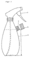
- the device according to the invention is shown in an embodiment as a two-neck bottle.
- the longer bottle neck (7) carrying the hand pump is shaped in such a way that it also serves as a lower handle for the hand pump (2).
- the shorter bottle neck (8) carries at its upper end at a distance (a) from the bottle bottom the filling opening (3), onto which a closure cap (5) containing a concentrate can be screwed.
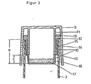
- FIGS 3 and 4 are detailed drawings of embodiments of the closure cap (5), which consists essentially of a screw cap (9) and a cup (10).
- the cup (10) which is preferably made of plastic, has in the upper section an outwardly directed edge (12) which is shaped in such a way that it fits on the upper edge of the filling opening (3) without protruding.
- the height (b) of the rim (12) defines the hanging depth of the cup (10) in the filling opening (3).
- the cup (10) tapers at an annular step (13) designed as a predetermined breaking point.
- the lower edge of the collar (11) serves as an abutting edge on which the ring step (13) sits flush.
- the cup (10) can be sealed with radially circumferential bead-shaped thickenings (14) to the outer circumferential surface of the collar (11) and (15) to the filling opening (3) carrying the sealing cap (5).
- the lower edge of the collar (11) presses on the ring step (13) designed as a predetermined breaking point and separates the cup (10) at height (c), the lower part (16) falling off and the filling material (17) emptied into the vessel (1).
- the lower part (16) of the cup (10) can also be designed as a flat disc, i.e. the predetermined breaking point is located directly at the bottom of the cup (10) or it is part of the cup base.
- FIG. 4 shows a special embodiment of the cup (10), in which the lower part (16) does not fall off when the closure cap (5) and the filling opening (3) are firmly connected, but rather is still attached to the ring step (13) at a point (18) . Since the screw cap (9) has to be screwed in by the distance (d) until it is completely tight, the collar (11) is also pushed down by the distance (d) and pushes the lower part of the cup to the side, so that the Filling material (17) is completely emptied or that a sufficiently large opening remains to wash out the filling material (17) with a diluent placed in the vessel (1) without the partially separated cup (16) serving as a barrier.
- the incomplete tearing off of the bottom (16) can be achieved by simple means, e.g. a partial thickening of the predetermined breaking point (13) in a narrowly limited area, by the choice of a plastic material that can be expanded under pressure loads, or by the fact that the abutting edge of the collar (11) only sits on the ring step (13) at one point.
- a cup (10) in which the bottom (16) can be completely removed it being possible in particular by simple measures to ensure that the opening of the reservoir - i.e. the falling off of the cup base (16) is indicated by a crack or a significant change in the resistance to rotation when the cap (5) is screwed on.
- the cup (10) can be removed when the closure cap (5) is unscrewed and does not get stuck in the filling opening (3). This is achieved when the cup (10) sits firmly on the outer surface of the collar (11) and is less tight against the inner surface of the filling opening (3).
- the reduced tightness of the closure cap (5) can be improved by an annular seal (19) inserted between the collar (11) and the outer screw cap.
- the device according to the invention is handled in such a way that the user fills the vessel (1) with the hand pump (2) through the second opening - the filling opening (3) - first with the diluent (4) - mostly water - and then a cap ( 5) in which the Kon concentrate (17) is screwed on.
- the cup (10) is separated and the concentrate (17) can be mixed with the diluent by shaking, without the user coming into contact with the concentrate (17).
- closure systems can also be used in which part of the filling opening is angular or pointed that the reservoir is closed when the closure cap (5) and filling opening are temporarily closed and is opened when the closure cap (5) and filling opening is firmly closed.
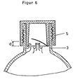
- FIG. 5 shows a closure cap (5) connected to the filling opening (3) in the provisional closure position.
- FIG. 6 which shows the same closure cap in the final closure position, the principle of operation of closure caps (5) is to be explained, in which the reservoir is opened by parts of the filling opening (3) which have an angular or pointed design.
- This type of closure cap which can be connected to the filling opening (3) by means of the thread (23), contains a collar (20) which rises vertically inwards from the base of the cap, the lower end of which is closed by a closure element (21).
- cap base (25), collar (20) and closure element (21) forms the reservoir into which the concentrate (17) is enclosed.
- the end element (21) is preferably a film which is tightly connected to the lower edge of the collar (20).
- one or more mandrels (22) are attached, which are aligned at a distance c from the inner wall parallel to the inner wall with their upper end towards the filling opening.
- the mandrel (22) can also be designed as a continuous ring step (24). This is illustrated by FIGS. 5b and 5c, which show a cross section through the filling opening at the height of the element (22) or (24).
- Figure 5b describes a possible arrangement of two mandrels (22), which are directed at a distance c from the inner wall of the filling opening (3) to the center of the filling opening.
- FIG. 5c relates to an element (24) designed as an annular step, which is likewise oriented at a distance c from the inner wall of the filling opening (3) to the center of the filling opening.
- the filling opening can be made both on the second, shorter neck of a two-neck bottle ( Figure 1) or laterally on the neck of a single-neck bottle carrying the hand pump (2) ( Figure 2), but should always be located below the hand pump (2) that it is arranged at a height between the bottle base and hand pump and thus determines two filling quantities in the device according to the invention.
- Filling quantity 1 is the maximum quantity of diluent (4) that can be filled into the bottle when held vertically.
- Filling quantity 2 is that above the correctly filled in diluent (4) with enclosed air volume.
- the dosage of the concentrate (17) is carried out by the manufacturer of the sealing cap (5) and is precisely matched to the amount of the diluent (4).
- the only requirement placed on the user is to fill the diluent (4) - usually water - through the filling opening (3) up to the level defined by the height a. Due to this simple handling, dosage errors can be excluded.
- the user can only fill the bottle with the diluent (4) - usually water - up to the level a specified by the filling opening (3). Above this level there is an amount of air predetermined by the total volume of the bottle. If the closure cap (5) containing the concentrate (17) is connected to the filling opening, the reservoir opens towards the diluent (4) as described above when the closure is tight. Because the reservoir is then either already immersed in the diluent or is just above it, the diluent (4) can rinse the reservoir and wash out the concentrate (17) even with slight shaking movements.
- filling quantity 2 due to the air included (filling quantity 2), the entire bottle content is mixed turbulently, which results in a particularly rapid and complete mixing of concentrate (17) and diluent (4).
- the ratio of the two filling quantities 2 and 1 is approximately 1:20 to 1: 2 (air to diluent) to ensure thorough mixing.
- a ratio of 1:10 to 1: 5 is preferred.
- the device according to the invention can be started with the device according to the invention immediately after the preparation of the spray liquor. This is achieved because the device according to the invention is constructed as a system which is closed to the outside and in which the concentrate which is available separately from the vessel (1) is enclosed in a reservoir, the opening of the reservoir and the mixing of concentrate and diluent inside the Systems take place and spraying without opening the system is possible so that the user never comes into contact with the concentrate or with foams of the spray mixture. Nevertheless, the device according to the invention enables optimal mixing with exact metering.
- the problem of the removal or the safe storage of the opened packages with pesticide concentrates does not apply to the device according to the invention, since the pesticide is kept safely in the closure cap until the point of use and no influences that destroy the active ingredient, such as light, air humidity, atmospheric oxygen etc. is exposed.
- the crop protection agents can be sprayed as an emulsion, suspension, dispersion or as a solution, and suitable emulsifiers and / or wetting agents can be added to the concentrate.
- sprayable liquids are suitable as diluents, but water is preferred.
- the device according to the invention makes it possible to spray substances which are not stable in solution, for example in water, over a long period of time, nevertheless in the form of dilute solutions, because the spray mixture is only produced shortly before use, but the substance as a concentrate in the form of a storage-stable formulation - run is stable without decomposition.
- Another important advantage of the device according to the invention is that physically unstable multiphase systems can also be used as a crop protection concentrate.
- systems in which two or more immiscible liquid or solid phases occur have hitherto been little known, since precise dosing is impossible if the entire contents of the container are not used at once.
- closure cap (5) remains on the vessel (1) until the spray liquor has been completely used up and the user always prints on this cap (5) via the in the Vessel (1) located means is informed.
- the use of the device according to the invention is not limited to the crop protection area. Rather, it can always be used advantageously if a mixture is prepared from a concentrate and a suitable diluent and is then discharged by spraying.
Description
- Die Erfindung betrifft eine Vorrichtung, mit der Konzentrate, insbesondere Pflanzenschutzmittel- konzentrate sicher und ohne Dosierungsfehler mit einer geeigneten Flüssigkeit auf Anwendungskonzentration verdünnt und durch Spritzen, Sprühen oder Vernebeln ausgebracht werden können.
- Eine der wichtigsten Ausbringungsformen von Pflanzenschutzmitteln ist das Versprühen von wäßrigen Pflanzenschutzmittel lösungen mit Spritzen. Es sind Spritzen unterschiedlicher Größe bekannt, bei denen das Sprühmittel mittels einer handoder motorbetriebenen Pumpe ausgebracht wird. Die Spritzbrühe wird erst kurz vor der Anwendung durch Verdünnen eines Wirkstoffkonzentrates mit Wasser oder einer anderen geeigneten Flüssigkeit hergestellt. Ein wesentlicher Nachteil dieses Verfahrens ist, daß der Anwender beim Mischen der Spritzbrühe mit dem Wirkstoffkonzentrat in Berührung kommt. Zudem sind Fehldosierungen leicht möglich und oftmals werden mehr Mittel ausgebracht, als zur Durchführung der Pflanzenschutzmaßnahme notwendig und sinnvoll sind. Außerdem gibt es Probleme mit der Beseitigung der Pflanzenschutzmittelreste bzw. mit der Aufbewahrung der nicht verbrauchten Pflanzenschutzmittelkonzentrate.
- Die hier geschilderten Nachteile treten besonders bei Kleinanwendern im Haus- und Gartenbereich auf, weil dieser Personenkreis oft nur geringste Mengen Pflanzenschutzmittel benötigt, durch die Vielfalt der von ihm kultivierten Pflanzen aber eine größere Zahl unterschiedlich wirksamer Pflanzenschutzmittel bereithält. So muß der Kleinanwender stets für eine ordnungsgemäße Lagerung bereits angebrochener Packungen von Wirkstoffkonzentraten Sorge tragen.
- Moderne Pflanzenschutzmittel sind so weit entwickelt, daß nur noch geringste Mengen aktiver Substanz benötigt werden, um die erwünschte Wirkung zu erreichen.
- Bei der Anwendung von Pflanzenschutzmitteln im Kleinverbraucherbereich sind zur Herrichtung der hier benötigten geringen Mengen Spritzbrühe (etwa 0,5 bis 10 I) nur noch kleinste Volumina an Lösungsmittelkonzentrat erforderlich. Das Abmessen dieser Konzentratmengen, die je Liter Spritzbrühe oftmals weniger als 1 ml betragen, ist sehr schwierig.
- Meßfehler, die zu Über- und Unterdosierungen führen, sind daher häufig. Eine Verdünnung des Lösungsmittelkonzentrates würde zwar die Genauigkeit beim Abmessen verbessern, hat aber den Nachteil, daß mehr Hilfsstoffe und Lösungsmittel verwendet werden, als zur Durchführung der Pflanzenschutzmaßnahmen erforderlich sind. Zudem sind verdünnte Lösungen instabiler als konzentrierte Lösungen.
- Auch werden Lösungsmittelkonzentrate häufig falsch dosiert, weil viele Anwender überfordert sind, aus den vom Hersteller empfohlenen Anwendungskonzentrationen die dem Fassungsvermögen der Druckspritze entsprechende Dosis an Wirkstoff-Konzentrat zu errechnen.
- Inzwischen werden auch auf Anwendungskonzentration verdünnte wäßrige Pflanzenschutzmittel-Lösungen angeboten, welche in Flaschen mit Pumpenzerstäubern abgefüllt sind. Dadurch sind Fehldosierungen ausgeschaltet und der Anwender kommt mit dem Wirkstoff-Konzentrat nicht in Kontakt.
- Die Lagerstabilität solcher wäßriger Formulierungen ist aber meist unbefriedigend. Zudem ist für derartige Flaschen der Lager- und Transportaufwand hoch, da die Lösungen in der Regel zu über 99 % Wasser enthalten.
- Zur Lösung des Problems der Lagerstabilität und der Dosiergenauigkeit wird in der DE-AS 19 39 086 ein Behälter zur Aufbewahrung und zum Ansesetzen einer Pflanzenschutzmittelspritzbrühe vorgeschlagen.
- In eine das Verdünnungsmittel enthaltende Flasche sind mehrere Becher engesteckt in denen das Konzentrat getrennt von Verdünnungsmittel aufbewahrt ist. Durch das Aufstecken einer Handpumpe durchstößt die Steigleitung der Pumpe die Becherböden von außen nach innen.
- Nach dichtem Verschluß der Handpumpe kann das Konzentrat mit dem Verdünnungsmittel vermischt und dann mit der Handpumpe versprüht werden.
- Mit dieser Vorrichtung ist das Problem mangelhafter Lagerstabilität gelöst, denn Wirkstoff und Verdünnungsmittel sind bis zum Zeitpunkt des Verbrauches voneinander getrennt. Ungelöst bleiben aber folgende Punkte, die wie folgt zusammengefaßt werden können:
- Die Konzentratbecher werden von außen nach innen geöffnet. Es besteht Gefahr unverdünnt auslaufenden Konzentrates.
- Die Steigleitung durchstößt die einzelnen Becherböden nur mit einem Umfang, der durch den Radius der Steigleitung begrenzt ist. Dadurch, und weil die Steigleitung in dieser Offnung verbleibt, können Verdünnungsmittel und Konzentrat nur unvollständig miteinander gemischt werden, besonders dann, wenn das Konzentrat höhere Viskositäten aufweist.
- Dadurch, daß die Steigleitung die Aufgabe besitzt, den Becherboden zu durchstoßen, muß diese eine sehr hohe Festigkeit haben und kann nicht flexibel sein. Dies führt dazu, daB die hergestellte Verdünnung nicht komplett durch Sprühen aus dem Behälter entfernt werden kann. Es verbleibt ein Rest an Verdünnung.
- Vom gesamten Systemaufbau her betrachtet, kann diese Vorrichtung nur dann sinnvoll angewendet werden, wenn Verdünnungsmittel und Konzentrat in einer Flasche zusamen abgepackt angeboten werden.
- Damit sind die vorstehend beschriebenen Probleme des hohen Lager- und Transportaufwandes nicht gelöst.
- Es gibt bisher noch keine voll zufriedenstell lende wiederverwendbare Vorrichtung zur Applikation von Pflanzenschutzmittel-Spritzbrüchen, welche die Gesichtspunkte von größtmöglicher Gebrauchssicherheit, guter Lagerstabilität, geringem Lager- und Transportaufwand sowie guter Mischbarkeit von Konzentrat und Verdünnungsmittel in sich vereinigt.
- Ziel der vorliegenden Erfindung ist es daher, eine Vorrichtung zu schaffen, in der all diese Punkte in einer einzigen Vorrichtung gelöst sind.
- Diese Aufgabe wird erfindungsgemäß durch eine Vorrichtung nach Anspruch 1 gelöst.
- Weitere Einzelheiten, Merkmale und Vorteile der Erfindung ergeben sich aus der Beschreibung und dem in den Zeichnungen rein schematisch dargestellten Ausführungsbeispiel.
- Es zeigen:
- Figur 1: Gefäß (1) mit Handpumpe (2), Füllöffnung (3) und Verschlußkappe (5) in Form einer Zweihalsflasche.
- Figur 2: Gefäß (1) mit Handpumpe (2), Verschlußkappe (5) und seitlich angeordneter Füllöffnung (3)
- Figur 3: Verschlußkappe (5) mit abtrennbarem Becherboden in vorläufiger Verbindung mit der Füllöffnung (3) und
- Figur 4: Verschlußkappe (5) mit abtrennbarem Becherboden bei fester Verbindung der Füllöffnung (3)
- Figur 5: Verschlußkappe (5) in vorläufiger Verbindung mit der Füllöffnung (3) (Figur 5a) sowie zwei Querschnitte durch die Füllöffnung (Figur 5b, 5c) in Höhe der Elemente (22) bzw. (24).
- Figur 6: Verschlußkappe (5) in fester Verbindung mit der Füllöffnung (3)
- Die Wirkungsweise der erfindungsgemäßen Vorrichtung wird zunächst anhand des in Figur 1, 3 und 4 dargestellten Ausführungsbeispiels erläutert:
- Gefäß (1) besitzt zwei Öffnungen, welche in verschiedener Höhe angebracht sind. Die eine Öffnung (6) dient als Befestigungspunkt für die Handpumpe (2).
- In Figur 1 ist die erfindungsgemäße Vorrichtung in einer Ausführungsform als Zweihalsflasche gezeigt. Der die Handpumpe tragende längere Flaschenhals (7) ist so ausgeformt, daß er zugleich als unteres Griffstück für die Handpumpe (2) dient. Der kürzere Flaschenhals (8) trägt an seinem oberen Ende im Abstand (a) vom Flaschenboden die Füllöffnung (3), auf die eine ein Konzentrat enthaltende Verschlußkappe (5) aufgeschraubt werden kann.
- Figur 3 und 4 sind Detailzeichnungen von Ausführungsformen der Verschlußkappe (5), die im wesentlichen aus einer Schraubkappe (9) und einem Becher (10) besteht.
- Im Innern der Schraubkappe befindet sich ein axial vom Boden ausgehender Kragen (11), auf dessen äußere Mantelfläche der Becher (10) aufgesteckt ist. Der vorzugsweise aus Kunststoff bestehende Becher (10) hat im oberen Abschnitt einen auswärtsgerichteten Rand (12), welcher so ausgeformt ist, daß er auf den oberen Rand der Füllöffnung (3) paßt, ohne überzustehen. Die Höhe (b) des Randes (12) definiert die Einhängtiefe des Bechers (10) in die Füllöffnung (3). In seinem unteren Teil verjüngt sich der Becher (10) an einer als Sollbruchstelle ausgebildten Ringstufe (13). Dabei dient der untere Rand des Kragens (11), als Stoßkante, auf dem die Ringstufe (13) bündig aufsitzt. Der Becher (10) kann mit radial umlaufenden wulstförmigen Verdickungen (14) zur äußeren Mantelfläche des Kragens (11) und (15) zu der die Verschlußkappe (5) tragenden Füllöffnung (3) abgedichtet werden. Beim Einschrauben der Verschlußkappe (5) drückt der untere Rand des Kragens (11) auf die als Sollbruchstelle ausgebildete Ringstufe (13) und zertrennt den Becher (10) in der Höhe (c), wobei der untere Teil (16) abfällt und das Füllgut (17) in das Gefäß (1) entleert. Der untere Teil (16) des Bechers (10) kann auch als flache Scheibe ausgebildet sein, d.h. die Sollbruchstelle befindet sich direkt am unteren Rand des Bechers (10) oder sie ist ein Bestandteil des Becherbodens.
- Figur 4 zeigt eine besondere Ausführungsform des Bechers (10), bei der der untere Teil (16) bei fester Verbindung von Verschlußkappe (5) und Füllöffnung (3) nicht abfällt, sondern an einer Stelle (18) der Ringstufe (13) noch anhängt. Da die Schraubkappe (9) bis zum vollständig dichten Sitz um die Strecke (d) eingeschraubt werden muß, wird auch der Kragen (11) um die Strecke (d) nach unten verschoben und drückt den unteren Teil des Bechers zur Seite, so daß das Füllgut (17) vollständig entleert wird oder daß eine hinreichend große Öffnung verbleibt um das Füllgut (17) mit einem im Gefäß (1) vorgelegten Verdünnungsmittel auszuwaschen ohne daß der teilweise abgetrennte Becher (16) als Sperre dienen kann.
- Das unvollständige Abreißen des Bodens (16) kann mit einfachen Mitteln erreicht werden, wie z.B. einer teilweisen Verdickung der Sollbruchstelle (13) in einem eng begrenzten Bereich, durch die Wahl eines unter Druckbelastungen dehnbaren Kunststoffmaterials oder dadurch, daß die Stoßkante des Kragens (11) nur an einer Stelle auf der Ringstufe (13) aufsitzt. Es kann aber auch ein Becher (10) verwendet werden, bei dem der Boden (16) vollständig abtrennbar ist, wobei insbesondere durch einfache Maßnahmen erreicht werden kann, daß das Öffnen des Reservoirs-d.h. das Abfallen des Becherbodens (16)-sich durch ein Knacken oder eine deutliche Änderung des Drehwiderstandes beim Verschrauben der Verschlußkappe (5) anzeigt. Durch einfache Maßnahmen kann sichergestellt werden, daß der Becher (10) beim Herausschrauben der Verschlußkappe (5) mit herausnehmbar ist und nicht in der Füllöffnung (3) stecken bleibt. Dies wird dadurch erreicht, wenn der Becher (10) fest auf der äußeren Mantelfläche des Kragens (11) sitzt und weniger fest an der inneren Fläche der Füllöffnung (3) anliegt. Die Verringerte Dichtigkeit der Verschlußkappe (5), kann durch eine zwischen Kragen (11) und äußere Schraubkappe eingelegte Ringdichtung (19) verbessert werden.
- Die Handhabung der erfindungsgemäßen Vorrichtung geschieht so, daß der Anwender das Gefäß (1) mit der Handpumpe (2) durch die zweite Öffnung - die Füllöffnung (3) - zunächst mit dem Verdünnungsmittel (4) - meist Wasser - füllt und danach eine Verschlußkappe (5) in der das Konzentrat (17) enthalten ist aufschraubt. Beim Verschrauben wird der Becher (10) getrennt und das Konzentrat (17) kann durch Schütteln mit dem Verdünnungsmittel gemischt werden, ohne daß der Anwender mit dem Konzentrat (17) in Berührung kommt.
- Neben den zu der Erläuterung des Wirkungsprinzips anhand der Zeichnungen 3 und 4 beschriebenen Verschlußkappen, bei denen das Reservoir mittels eines kantig ausgebildeten Teils der Verschlußkappe geöffnet wird, können auch Verschlußkappen-Systeme verwendet werden, bei denen ein Teil der Füllöffnung dergestalt kantig oder spitz ausgebildet ist, daß das Reservoir bei vorläufigem Verschluß von Verschlußkappe (5) und Füllöffnung verschlossen und bei festem Verschluß von Verschlußkappe (5) und Füllöffnung geöffnet ist.
- Figur 5 zeigt eine mit der Füllöffnung (3) in vorläufiger Verschlußstellung verbundene Verschlußkappe (5). Anhand dieser Zeichnung und anhand von Figur 6, welche dieselbe Verschlußkappe in endgültiger Verschlußstellung zeigt, soll das Wirkungsprinzip von Verschlußkappen (5) erläutert werden, bei denen das Reservoir durch kantig oder spitz ausgebildete Teile der der Füllöffnung (3) geöffnet wird.
- Dieser Verschlußkappentyp der mittels des Gewindes (23) mit der Füllöffnung (3) verbunden werden kann enthält einen senkrecht vom Kappenboden nach innen rechenden Kragen (20), dessen unteres Ende mit einem Abschlßelement (21) verschlossen ist.
- Der durch die Elemente Kappenboden (25), Kragen (20) und Abschlußelement (21) begrenzte Hohlraum bildet das Reservoir, in welches das Konzentrat (17) eingeschlossen ist.
- Da Abschlußelement (21) ist vorzugsweise eine mit dem unteren Rand des Kragens (20) dicht verbundenen Folie. An der Innenwand der Füllöffnung (3) sind ein oder mehrere Dorne (22) angebracht, die im Abstand c von der Innenwand parallel zur Innenwand mit ihrem oberen Ende zur Füllöffnung hin ausgerichtet sind. Beim Verschrauben der Verschlußkappe (5) bis zum festen Sitz wird das Reservoir um die Strecke d in die Füllöffnung hinein verschoben. Das Element (22) durchtrennt das Element (21) so daß die Verbindung zwischen dem Reservoir und dem Verdünnungsmittel hergestellt ist.
- Der Dorn (22) kann auch als durchlaufende Ringstufe (24) ausgebildet sein. Dies sei anhand der Fig. 5b und 5c verdeutlicht, die einen Querschnitt durch die Füllöffnung in der Höhe des Elements (22) bzw. (24) zeigen.
- Figur 5b beschreibt eine mögliche Anordnung von zwei Dornen (22), die im Abstand c von der Innenwand der Füllöffnung (3) zur Mitte der Füllöffnung hinausgerichtet sind. Figur 5c betrifft ein als Ringstufe ausgebildetes Element (24), welches ebenfalls im Abstand c von der Innenwand der Füllöffnung (3) zur Mitte der Füllöffnung hin ausgerichtet ist.
- Weitere Verschlußkappen (5), die durch Elemente die der Füllöffnung zuzuordnen sind geöffnet werden, sind in der deutschen Gebrauchsmusteranmeldung DE-GB 85 02 007 beschrieben auf die hiermit Bezug genommmen wird.
- Die Füllöffnung kann sowohl auf dem zweiten, kürzeren Hals einer Zweihalsflasche (Figur 1) oder aber seitlich an dem die Handpumpe (2) tragenden Hals einer Einhalsflasche angebracht sein (Figur 2), soll sich aber stets unterhalb der Handpumpe (2) befinden, so daß sie in der Höhe a zwischen Flaschenboden und Handpumpe angeordnet ist und somit zwei Füllmengen in der erfindungsgemäßen Vorrichtung bestimmt.
- Füllmenge 1 ist die bei senkrechter Haltung maximal in die Flasche einfüllbare Menge an Verdünnungsmittel (4).
- Füllmenge 2 ist das über dem vorschriftsmäßig eingefüllten Verdünnungsmittel (4) mit eingeschlossene Luftvolumen.
- Die Vorteile der erfindungsgemäßen Vorrichtung zeigen sich insbesondere bei der Herstellung von Pflanzenschutzmittelspritzbrühen:
- Die Dosierung des Konzentrats (17) wird vom Hersteller der Verschlußkappe (5) durchgeführt und ist genau auf die Menge des Verdünnungsmittels (4) abgestimmt. Die einzige Anforderung die an den Anwender gestellt ist besteht darin, das Verdünnungsmittel (4) - meist Wasser - durch die Füllöffnung (3) bis auf das durch die Höhe a definierte Niveau einzufüllen. Aufgrund dieser einfachen Handhabung können Dosierungsfehler ausgeschlossen werden.
- Der Anwender kann bei bestimmungsgemäßem Gebrauch die Flasche nur bis auf das durch die Füllöffnung (3) vorgegebene Niveau a mit dem Verdünnungsmittel (4) - meist Wasser - füllen. Oberhalb dieses Niveaus befindet sich eine durch das Gesamtvolumen der Flasche vorgegebene Menge an Luft. Wird die das Konzentrat (17) enthaltende Verschlußkappe (5) mit der Füllöffnung verbunden, so öffnet sich bei festem Verschluß wie zuvor beschrieben das Reservoir zum Verdünnungsmittel (4) hin. Weil das Reservoir dann entweder bereits in das Verdünnungsmittel eingetaucht ist oder kurz darüber steht, kann das Verdünnungsmittel (4) bereits bei leichten Schüttelbewegungen das Reservoir durchspülen und das Konzentrat (17) auswaschen. Des weiteren wird durch die mit eingeschlossene Luft (Füllmenge 2) der gesamte Flascheninhalt turbulent durchmischt was eine besonders schnelle und vollständige Durchmischung von Konzentrat (17) und Verdünnungsmittel (4) bewirkt. Das Verhältnis der beiden Füllmengen 2 und 1 beträgt etwa 1:20 bis 1:2 (Luft zu Verdünnungsmittel), um eine gute Durchmischung sicherzustellen. Bevorzugt ist ein Verhältnis von 1:10 bis 1:5.
- Die Verbesserung der Durchmischung von Verdünnungsmittel (4) und Konzentrat (17) durch den Einschluß einer definierten Luftmenge zeigt sich insbesondere dann wenn:
- - geringe Konzentratmengen (17) mit großen Mengen an Verdünnungsmittel (4) mit einander durchmischt werden sollen.
- - Konzentrat (17) und Verdünnungsmittel (4) unterschiedliche Viskosität haben.
- - das Konzentrat (17) als Feststoff (Pulver) vorliegt.
- - das Konzentrat (17) mit dem Verdünnungsmittel (4) trotz Zugabe von Detergentien nur schwer gelöst bzw. benetzt wird.
- - als Produkt der Mischung von Konzentrat (17) und Verdünnungsmittel (4) Micellen des Konzentrates in Verdünnungsmittel erzielt werden sollen.
- Die meisten Pflanzenschutzmittelkonzentrate enthalten Detergentien, die bei turbulenter Durchmischung mit Luft schäumen, wobei diese Schäume noch mehrere Minuten nach dem Mischvorgang nachsteigen. Bei frisch angesetzten Pflanzenschutzmittel-Spritzbrühen muß deshalb mit dem Umfüllen in die Spritze gewartet werden, bis der Schaum gebrochen ist. Demgegenüber kann bei der erfindungsgemäßen Vorrichtung unmittelbar nach dem Ansetzen der Spritzbrühe mit deren Ausbringen begonnen werden. Dies wird erreicht, weil die erfindungsgemäße Vorrichtung als ein nach außen geschlossenes System aufgebaut ist bei dem das vom Gefäß (1) getrennt zur Verfügung stehende Konzentrat in einem Reservoir eingeschlossen ist, wobei das Öffnen des Reservoirs sowie die Vermischung von Konzentrat und Verdünnungsmittel im Innern des Systems stattfinden und auch das Verspühen ohne Öffnen des Systems möglich ist so daß der Anwender zu keinem Zeitpunkt mit dem Konzentrat oder mit Schäumen der Spritzbrühe in Kontakt kommt. Dennoch kann durch die erfindungsgemäße Vorrichtung eine optimale Durchmischung bei exakter Dosierung erzielt werden.
- Die verhesserte Durchmischung von Konzentrat (17) und Verdünnungsmittel (4) in der erfindungsgemäßen Vorrichtung, sowie deren verbesserte Gebrauchssicherheit zeigt sich insbesondere im Vergleich mit der aus der DE-AS 19 39 068 bekannten Vorrichtung. Hier sind Füllöffnung und Spenderöffnung der gleichen Flaschenöffnung zugeordnet. Daher muß die Steigleitung der Handpumpe notwendigerweise das Reservoir zuerst nach außen hin öffnen, bevor es zum Verdünnungsmittel hin geöffnet werden kann. Das Reservoir ist zum Verdünnungsmittel nur in dem Umfang geöffnet, wie es mit der Steigleitung zerstochen werden kann. Weil außerdem die Steigleitung noch in dieser Öffnung verbleibt wird das Ausspülen des Konzentrates erheblich erschwert.
- Das Problem der Beseitigung oder der sicheren Lagerung der angebrochenen Packungen mit Pflanzenschutzmittel-Konzentraten entfällt bei der erfindungsgemäßen Vorrichtung, da bis zum Zeitpunkt des Verbrauchs das Pflanzenschutzmittel in der Verschlußkappe sicher verwahrt ist und keinerlei den Wirkstoff zersetzenden Einflüssen, wie Licht, Luftfeuchtigkeit, Luftsauerstoff etc. ausgesetzt ist. Die Pflanzenschutzmittel können als Emulsion, Suspension, Dispersion oder als Lösung versprüht werden, wobei dem Konzentrat geeignete Emulgier- und/oder Netzmittel zugesetzt werden können.
- Als Verdünnungsmittel sind grundsätzlich alle versprühbaren Flüssigkeiten geeignet, Wasser wird jedoch bevorzugt. Die erfindungsgemäße Vorrichtung ermöglicht es, Stoffe die in Lösung, z.B. in Wasser, über längere Zeit nicht stabil sind, dennoch in Form verdünnter Lösungen zu versprühen, weil die Spritzbrühe erst kurz vor Gebrauch hergestellt wird, der Stoff aber als Konzentrat in Form einer lagerstabilen Formulie- rung unzersetzt haltbar ist.
- Ein weiterer wesentlicher Vorteil der erfindungsgemäßen Vorrichtungliegt darin begründet, daß auch physikalisch instabile Mehrphasensysteme als Pflanzenschutzmittel-Konzentrat Verwendung finden können. In der konventionellen Pflanzenschutztechnik sind Systeme, in denen zwei oder mehrere nicht mischbare flüssige oder feste Phasen auftreten, bisher wenig bekannt, da eine genaue Dosierung unmöglicht ist, wenn nicht der gesamte Inhalt des Gebindes auf einmal verwendet wird.
- Deshalb haben sich entmischende mehrphasige Pflanzenschutzmittel-Konzentrate bisher keine Anwendung gefunden. Bei der erfindungsgemäßen Vorrichtung werden jedoch alle der Verschlußkappe (5) eingefüllten Stoffe in die Spritze umgefüllt. Dabei ist es unerheblich, ob das Konzentrat aus einer homogenen Phase oder aus einem mehrphasigen System besteht.
- Ein weiterer die Gebrauchssicherheit von Pflanzenschutzmittel- Spritzbrühen betreffender Vorteil ist darin zu sehen, daß die Verschlußkappe (5) bis zum vollständigen Verbrauch der Spritzbrühe auf dem Gefäß (1) verbleibt und der Anwender durch Aufdrucke auf dieser Kappe (5) stets über das in dem Gefäß (1) befindliche Mittel informiert ist.
- Die Verwendung der erfindungsgemäßen Vorrichtung ist nicht auf den Pflanzenschutzbereich beschränkt. Vielmehr kann sie stets dann vorteilhaft eingesetzt werden, wenn aus einem Konzentrat und einem geeigneten Verdünnungsmittel eine Mischung hergestellt und dann durch Versprühen ausgetragen wird.
- So ist sie z.B. anwendbar für Mittel zur Desinfektion; zum Aufbringen von Lack- oder Klebefilmen, wobei beispielsweise ein Härter in der Verschlußkappe als Konzentrat Verwendung findet, außerdem für Reinigungs- oder Konservierungsmittel.
- 1 Gefäß
- 2 Handpumpe
- 3 Füllöffnung
- 4 Verdünnungsmittel
- 5 Verschlußkappe
- 6 Öffnung f. Handpumpe
- 7 längerer Flaschenhals
- 8 kurzerer Flaschenhals
- 9 Schraubkappe
- 10 Becher
- 11 Kragen
- 12 auswärts gerichteter Rand
- 13 Ringstufe
- 14 wulstförmige Verdickungen (kragenseitig)
- 15 wulstförmige Verdickungen (Mantelinnenfläche)
- 16 unterer Teil des Bodens
- 17 Füllgut, Konzentrat
- 18 Verdickung der Sollbruchstelle
- 19 Ringdichtung
- 20 Kragen
- 21 Abschlußelement
- 22 Dorn
- 23 äußeres Gewinde
- 24 Ringstufe
- 25 Kappenboden
Claims (8)
dadurch gekennzeichnet, daß
die, Verschlußkappe (5) aus einer Schraubkappe mit einem axial vom Boden der Schraubkappe nach innen reichenden Kragen (1) und einem auf diesen Kragen (11) aufgesteckten Becher (10), der als Reservoir dient, besteht und daß sich der Becher (10) längs einer radial ausgebildeten Ringstufe (13), die als Sollbruchstelle dient, verjüngt, so daß der untere Rand des Kagens (11) ganz oder teilweise als Stoßkante im Innern des Bechers auf dieser Ringstufe (13) aufsitzt und daß der Becher (10) in seinem oberen Abschnitt einen auswärts gerichteten Rand (12) besitzt, der so bemessen ist, daß er paßgenau auf dem oberen Rand der Füllöffnung (3) aufsitzt.
dadurch gekennzeichnet,
daß die Verschlußkappe (5) aus einer Schraubkappe und einem axial vom Boden der Schraubkappe nach innen reichenden Kragen (11) und einem auf diesen Kragen aufgesteckten Becher, der als Reservoir dient, besteht und daß der Boden des Bechers auf dem als Stoßkante dienenden unteren Rand des Kragens (11) aufsitzt und daß der Becher an seinem unteren Rand oder auf seinem Boden eine Sollbruchstelle aufweist und in seinem oberen Abschnitt einen auswärts gerichteten Rand besitzt, der so bemessen ist, daß er paßgenau auf dem oberen Rand der Füllöffnung (3) aufsitzt.
dadurch gekennzeichnet,
daß die Verschlußkappe (5) aus einer Schraubkappe mit einem axial vom Schraubkappenboden nach innen reichenden Kragen (20) und einem mit dem unteren Rand des Kragens (20) dicht abschließenden Abschlußelement (21) besteht, wobei ein oder mehrer von der Innenwand der Füllöffnung (3) ins Innere reichende und zum oberen Rand der Füllöffnung (3) hin ausgerichtete und mit der Wandung der Füllöffnung (3) starr verbundene Dorne (22) oder eine Ringstufe (24) so angeordnet sind, daß bei vorliegender Verbindung von Verschlußkappe (5) und Füllöffnung (3) das Abschlußelement (21) die Dorne (22) oder die Ringstufe (24) nicht berührt und bei fester Verbindung von Verschlußkappe (5) und Füllöffnung (3) die Dorne (22) oder die Ringstufe (24) das in die Füllöffnung hinein verschobene Abschlußelement (21) durchstoßen.
Priority Applications (1)
| Application Number | Priority Date | Filing Date | Title |
|---|---|---|---|
| AT85109266T ATE53555T1 (de) | 1984-08-04 | 1985-07-24 | Misch- und spruehvorrichtung. |
Applications Claiming Priority (2)
| Application Number | Priority Date | Filing Date | Title |
|---|---|---|---|
| DE8423325U DE8423325U1 (de) | 1984-08-04 | 1984-08-04 | Misch- und Sprühvorrichtung |
| DE8423325U | 1984-08-04 |
Publications (3)
| Publication Number | Publication Date |
|---|---|
| EP0170980A2 EP0170980A2 (de) | 1986-02-12 |
| EP0170980A3 EP0170980A3 (en) | 1987-11-11 |
| EP0170980B1 true EP0170980B1 (de) | 1990-06-13 |
Family
ID=6769562
Family Applications (1)
| Application Number | Title | Priority Date | Filing Date |
|---|---|---|---|
| EP19850109266 Expired - Lifetime EP0170980B1 (de) | 1984-08-04 | 1985-07-24 | Misch- und Sprühvorrichtung |
Country Status (13)
| Country | Link |
|---|---|
| US (1) | US4705191A (de) |
| EP (1) | EP0170980B1 (de) |
| JP (1) | JPH0622716B2 (de) |
| AT (1) | ATE53555T1 (de) |
| AU (1) | AU577881B2 (de) |
| CA (1) | CA1308082C (de) |
| DE (2) | DE8423325U1 (de) |
| DK (1) | DK161135C (de) |
| ES (1) | ES295875Y (de) |
| FI (1) | FI85457C (de) |
| FR (1) | FR2568547B1 (de) |
| NZ (1) | NZ212970A (de) |
| ZA (1) | ZA855845B (de) |
Cited By (1)
| Publication number | Priority date | Publication date | Assignee | Title |
|---|---|---|---|---|
| US11052415B2 (en) | 2016-03-10 | 2021-07-06 | Ecolab Usa Inc. | Measured dosing and spray bottle for multi-use applications and associated method of using |
Families Citing this family (95)
| Publication number | Priority date | Publication date | Assignee | Title |
|---|---|---|---|---|
| US4805814A (en) * | 1987-08-03 | 1989-02-21 | National Products Division | Container for liquids having a mounting boss for storage of a removable dispenser |
| US4832230A (en) * | 1987-12-15 | 1989-05-23 | Janowitz C Michael | Threaded cap containing additive for containers |
| US4932563A (en) * | 1988-08-22 | 1990-06-12 | Diamond Lee G | Combined jug and sprayer |
| US4903865A (en) * | 1988-09-19 | 1990-02-27 | Janowitz C Michael | Push button cap containing an additive for containers |
| US4925066A (en) * | 1988-10-26 | 1990-05-15 | Mission Kleensweep Products, Inc. | Combined sprayer and refill container |
| DE3904759A1 (de) * | 1989-02-16 | 1990-08-23 | Hora Landwirt Betrieb | Vorrichtung zum ausbringen von pflanzenschutzmitteln |
| JP2518300Y2 (ja) * | 1989-12-08 | 1996-11-27 | 株式会社吉野工業所 | 液体収納容器付きのポンプ式混合液体吐出容器 |
| JP2537883Y2 (ja) * | 1989-12-25 | 1997-06-04 | 株式会社吉野工業所 | 連結チューブ付きのポンプ式混合液体吐出容器 |
| DE4016282A1 (de) * | 1990-05-21 | 1991-11-28 | Finke Robert Gmbh | Mehrkomponenten-packung |
| US5402916A (en) * | 1993-06-22 | 1995-04-04 | Nottingham Spirk Design Associates | Dual chamber sprayer with metering assembly |
| US5419077A (en) * | 1993-11-08 | 1995-05-30 | Tombarelli; David | Liquid for neutralizing bugs and a method and liquid disbursing device to cover bugs |
| EP0674948A1 (de) * | 1994-03-28 | 1995-10-04 | The Procter & Gamble Company | Nachfüllbare Sprühdose |
| US20030000961A1 (en) * | 1994-07-25 | 2003-01-02 | Klima William L. | Dispenser |
| US5947332A (en) * | 1994-07-25 | 1999-09-07 | Sprayex, Inc. | Rechargeable dispensers |
| WO1996003344A1 (en) * | 1994-07-25 | 1996-02-08 | Klima William L | Rechargeable dispensers |
| US5529216A (en) * | 1994-07-25 | 1996-06-25 | Spraytec Systems | Rechargeable dispensers |
| US5890624A (en) * | 1994-07-25 | 1999-04-06 | Sprayex L.L.C. | Rechargeable dispensers |
| US6319453B1 (en) * | 1994-07-25 | 2001-11-20 | Sprayex, Inc. | Method of making a multiple neck spray bottle |
| US5836479A (en) * | 1994-07-25 | 1998-11-17 | Sprayex L.L.C. | Rechargeable containers and dispensers |
| US5542581A (en) * | 1994-11-25 | 1996-08-06 | Habora; Barbara M. | Dual service sprayer |
| IT237024Y1 (it) * | 1995-07-11 | 2000-08-31 | Coster Tecnologie Speciali Spa | Vaporizzatore di liquidi con tappo di caricamento |
| US5788125A (en) * | 1996-06-10 | 1998-08-04 | Steiner; Edward H. | Sip and spray fluid container assembly |
| GB2317870A (en) * | 1996-10-04 | 1998-04-08 | Naomi Schefrin Stein | Container with openable closure between two compartments |
| AU726880B2 (en) * | 1997-03-27 | 2000-11-23 | Diversey, Inc. | Device for storing a liquid, particularly a dilutable concentrate, co-operable with a spray dispenser |
| IT1293005B1 (it) * | 1997-06-10 | 1999-02-11 | Bernardino Parise | Contenitore per sostanze concentrate in polvere o liquide da porre in soluzione entro un involucro al momento dell'uso |
| USD405008S (en) * | 1997-08-14 | 1999-02-02 | The Procter & Gamble Company | Dispensing package |
| US5839616A (en) * | 1997-08-14 | 1998-11-24 | The Procter & Gamble Company | Blow molded container having pivotal connector for an actuation lever |
| USD418404S (en) * | 1998-07-01 | 2000-01-04 | The Procter & Gamble Company | Dispensing package |
| US6092952A (en) * | 1998-07-22 | 2000-07-25 | Eberle; Jim J. | Bottle mounted applicator for automotive detailing |
| IT244349Y1 (it) * | 1998-11-04 | 2002-03-11 | Maplast Srl | Flacone per prodotti cosmetici farmaceutici per tinture per capelli esimili a componenti separati |
| US6808085B2 (en) * | 1999-07-16 | 2004-10-26 | Ing. Erich Pfeiffer Gmbh | Media dispenser |
| US6398132B1 (en) * | 1999-04-12 | 2002-06-04 | Circulair, Inc. | Cooling device using fan-driven misting with large fill and drinking port |
| US20020148909A1 (en) * | 1999-04-12 | 2002-10-17 | Junkel Eric F. | Cooling device using fan-driven misting with large bottom fill port |
| US6206243B1 (en) | 1999-06-09 | 2001-03-27 | Alterra Holdings Corporation | Collapsible spray bottle |
| US20030038186A1 (en) * | 2000-06-13 | 2003-02-27 | Klima William L. | Rechargeable dispensers |
| US6290100B1 (en) | 2000-06-30 | 2001-09-18 | Canberra Corporation | Concentrate cartridge for a diluting and dispensing container |
| GB2369609B (en) * | 2000-11-04 | 2006-02-08 | Bettix Ltd | Bottle |
| US6938805B2 (en) * | 2001-03-14 | 2005-09-06 | Kenneth Brincat | Refillable bottle and system of reuse |
| US6691892B2 (en) | 2001-03-21 | 2004-02-17 | Chapin Manufacturing, Inc. | Granular pump |
| US7093741B2 (en) * | 2002-04-16 | 2006-08-22 | Andrew Durant | Applicator and integrated concentrate system |
| EP1497187A2 (de) * | 2002-04-16 | 2005-01-19 | Andrew Durant | Auftragsvorrichtung und integriertes konzentratsystem |
| US20050161529A1 (en) * | 2002-04-16 | 2005-07-28 | Andrew Durant | Applicator and integrated concentrate system |
| US7055684B2 (en) * | 2002-05-24 | 2006-06-06 | Anderson Michael R | Dispensing capsule for a liquid container |
| US20040232170A1 (en) * | 2003-05-23 | 2004-11-25 | Jonathan Glick | Anti-monster kit and method of use |
| US20050084583A1 (en) * | 2003-10-17 | 2005-04-21 | Pascal Genini | Pancake bottle |
| AT500486B1 (de) * | 2004-03-05 | 2006-11-15 | Hagleitner Hans Georg | Verfahren zur herstellung verdünnter lösungen |
| US7959040B2 (en) * | 2004-03-18 | 2011-06-14 | Rust-Oleum Netherlands B.V. | Dispensing device for dispensing a product |
| JP2006001610A (ja) * | 2004-06-18 | 2006-01-05 | Sumitomo Chemical Co Ltd | 農薬容器 |
| JP4970040B2 (ja) * | 2004-09-29 | 2012-07-04 | 株式会社吉野工業所 | 二液等混合容器 |
| FR2885356B1 (fr) * | 2005-05-04 | 2010-04-23 | Eric Paul Marcel Dufay | Receptacle pour la distribution d'un produit qu'il contient a l'interieur d'un recipient a goulot |
| ITMI20050191U1 (it) | 2005-05-23 | 2006-11-24 | Pi Esse Plastic S R L | Dispositivo di ricarica per erogatore a spruzzo ricaricabile ed erogatore a spruzzo ricaricabile |
| US8016996B2 (en) | 2006-02-10 | 2011-09-13 | Tennant Company | Method of producing a sparged cleaning liquid onboard a mobile surface cleaner |
| US8025786B2 (en) | 2006-02-10 | 2011-09-27 | Tennant Company | Method of generating sparged, electrochemically activated liquid |
| US8156608B2 (en) * | 2006-02-10 | 2012-04-17 | Tennant Company | Cleaning apparatus having a functional generator for producing electrochemically activated cleaning liquid |
| US7891046B2 (en) * | 2006-02-10 | 2011-02-22 | Tennant Company | Apparatus for generating sparged, electrochemically activated liquid |
| US8025787B2 (en) | 2006-02-10 | 2011-09-27 | Tennant Company | Method and apparatus for generating, applying and neutralizing an electrochemically activated liquid |
| US8012340B2 (en) | 2006-02-10 | 2011-09-06 | Tennant Company | Method for generating electrochemically activated cleaning liquid |
| US8007654B2 (en) | 2006-02-10 | 2011-08-30 | Tennant Company | Electrochemically activated anolyte and catholyte liquid |
| US7836543B2 (en) * | 2006-02-10 | 2010-11-23 | Tennant Company | Method and apparatus for producing humanly-perceptable indicator of electrochemical properties of an output cleaning liquid |
| US8046867B2 (en) * | 2006-02-10 | 2011-11-01 | Tennant Company | Mobile surface cleaner having a sparging device |
| US20090230153A1 (en) * | 2006-07-27 | 2009-09-17 | Knight John B | Dispensing Package and Methods of Using and Making |
| US20080023499A1 (en) * | 2006-07-27 | 2008-01-31 | Knight John B | Dispensing package and methods of using and making |
| US7938258B2 (en) * | 2006-10-05 | 2011-05-10 | E.I.D. Parry (India) Limited | Container assembly |
| US20080121655A1 (en) * | 2006-11-27 | 2008-05-29 | William Schultz | Dispensing systems and methods for liquid materials |
| US20080149585A1 (en) * | 2006-12-20 | 2008-06-26 | Valentine Craig R | Flavor cap |
| FR2912956B1 (fr) * | 2007-02-23 | 2009-11-20 | Lafuente Jose Francis Sanchez | Le kit artistique |
| WO2009046279A2 (en) | 2007-10-04 | 2009-04-09 | Tennant Company | Method and apparatus for neutralizing electrochemically activated liquids |
| US20090120460A1 (en) * | 2007-11-09 | 2009-05-14 | Tennant Company | Soft floor pre-spray unit utilizing electrochemically-activated water and method of cleaning soft floors |
| WO2009149327A2 (en) | 2008-06-05 | 2009-12-10 | Global Opportunities Investment Group, Llc | Fuel combustion method and system |
| WO2009152149A2 (en) * | 2008-06-10 | 2009-12-17 | Tennant Company | Steam cleaner using electrolyzed liquid and method therefor |
| US20090311137A1 (en) * | 2008-06-11 | 2009-12-17 | Tennant Company | Atomizer using electrolyzed liquid and method therefor |
| WO2009155521A1 (en) * | 2008-06-19 | 2009-12-23 | Tennant Company | Tubular electrolysis cell comprising concentric electrodes and corresponding method |
| KR20110031190A (ko) * | 2008-06-19 | 2011-03-24 | 텐난트 컴파니 | 일정한 출력을 갖는 전기분해 디-스케일링 방법 |
| WO2010028031A2 (en) * | 2008-09-02 | 2010-03-11 | Tennant Company | Electrochemically-activated liquid for cosmetic removal |
| US8157131B2 (en) * | 2008-10-15 | 2012-04-17 | Sim Jae K | Spray bottle with refill cartridge |
| US8302816B2 (en) * | 2008-10-15 | 2012-11-06 | Sim Jae K | Spray bottle with refill cartridge |
| US8261943B2 (en) * | 2008-10-15 | 2012-09-11 | Sim Jae K | Spray bottle with refill cartridge |
| US8371315B2 (en) | 2008-12-17 | 2013-02-12 | Tennant Company | Washing systems incorporating charged activated liquids |
| US8967434B2 (en) | 2010-06-24 | 2015-03-03 | L&F Innoventions Llc | Self-adjusting handle for spray bottles |
| US8430137B2 (en) | 2010-08-24 | 2013-04-30 | Jae K. Sim | Refill cap cartridge |
| JP5684549B2 (ja) * | 2010-11-30 | 2015-03-11 | 株式会社吉野工業所 | 液体吐出容器 |
| JP5611788B2 (ja) * | 2010-11-30 | 2014-10-22 | 株式会社吉野工業所 | 液体吐出容器 |
| USD669364S1 (en) | 2011-05-17 | 2012-10-23 | Global Oppurtunities Investment Group, LLC | Spray apparatus |
| US9783339B1 (en) * | 2011-07-25 | 2017-10-10 | LJA Companies, LLC | Reusable dispensing apparatus |
| US8523017B2 (en) | 2011-09-22 | 2013-09-03 | Veltek Associates, Inc. | Mixing and dispensing apparatus |
| US8366023B1 (en) * | 2011-10-05 | 2013-02-05 | Ableman International Co., Ltd. | Handheld sprayer structure |
| DE102012002497A1 (de) * | 2012-02-10 | 2013-08-14 | Fresenius Medical Care Deutschland Gmbh | Verbinder mit einem Behälter zur Herstellung einer individuell angepassten Lösung für die Dialyse |
| US9216431B2 (en) | 2012-06-22 | 2015-12-22 | L&F Innoventions, LLC | Satellite spray bottle use and refill systems |
| US9505015B2 (en) | 2013-05-21 | 2016-11-29 | S. C. Johnson & Son, Inc. | Trigger sprayer with bottle filling conduit |
| US9884148B2 (en) * | 2014-05-30 | 2018-02-06 | Neilmed Pharmaceuticals, Inc. | Angular cap for dispensing liquids |
| MX2017001505A (es) | 2014-08-08 | 2017-05-09 | Colgate Palmolive Co | Sistema de empaquetado, almacenamiento primario y envase de relleno para el mismo. |
| USD802439S1 (en) * | 2015-11-02 | 2017-11-14 | Indian Institute Of Technology, Bombay | Spray bottle assembly |
| CA3040672A1 (en) * | 2018-10-10 | 2020-04-10 | Chapin Manufacturing, Inc. | Mix on demand smart backpack sprayer |
| TWD207428S (zh) * | 2019-06-18 | 2020-10-01 | 瑞士商勞拉斯塔股份有限公司 | 用於衣物掛燙的蒸氣產生器 |
| EP4086008A1 (de) * | 2021-05-04 | 2022-11-09 | Aptar Radolfzell GmbH | Tropfenspender, flüssigkeitsspender und verfahren zur herstellung eines flüssigkeitsspenders |
Family Cites Families (19)
| Publication number | Priority date | Publication date | Assignee | Title |
|---|---|---|---|---|
| US727144A (en) * | 1902-04-15 | 1903-05-05 | Joel W Johnson | Liquid filling and indicating device. |
| FR627048A (fr) * | 1926-01-05 | 1927-09-24 | Pharmagans Pharmaceutisches In | Ampoule |
| FR1039339A (fr) * | 1951-07-03 | 1953-10-06 | Récipient à séparateur, notamment pour produits à conserver isolés et à mélanger au moment de l'utilisation | |
| US3156369A (en) * | 1962-09-19 | 1964-11-10 | Ethicon Inc | Bicameral container |
| GB1083335A (en) * | 1963-05-28 | 1967-09-13 | Calmic Ltd | Storing, mixing and dispensing devices,e.g. for antibiotics |
| DE1939086C3 (de) * | 1969-07-31 | 1975-01-09 | Wolf Geraete Gmbh | Behälter zur Aufbewahrung und zum Ansetzen einer mindestens eine zu lösende Komponente enthaltenden Flüssigkeit |
| US3655096A (en) * | 1969-10-22 | 1972-04-11 | Pillsbury Co | Container for diluting and dispensing material |
| FR2153767A5 (de) * | 1971-09-23 | 1973-05-04 | Gallia Sa Eugene | |
| IT996631B (it) * | 1973-08-31 | 1975-12-10 | Guala R E Sas | Dispositivo di chiusura per flaco ni e simili provvisto di sigillo di garanzia ed incorporante un con tenitore perforabile per sostanze da immettere nel flacone |
| DE2432290A1 (de) * | 1974-07-05 | 1976-01-22 | Erich Wunsch | Verschlossenes kleinbehaeltnis |
| FR2306898A1 (fr) * | 1975-04-08 | 1976-11-05 | Isodio | Dispositif de melange de produits contenus dans des recipients clos |
| US3966089A (en) * | 1975-04-25 | 1976-06-29 | Colgate-Palmolive Company | Diluting and dispensing container |
| DE2638561A1 (de) * | 1976-08-26 | 1978-03-02 | Hago Chemie Gmbh & Co | Vorrichtung zur getrennten aufbewahrung und anschliessenden vermischung fliessfaehiger und/oder loeslicher stoffe |
| IT1090191B (it) * | 1976-10-26 | 1985-06-18 | Colgate Palmolive Co | Confezione per due componenti da mantere separati fino al momento dell'uso |
| GB2095637B (en) * | 1981-03-16 | 1984-10-31 | Macfarlane George William | Liquid dispenser |
| FR2506726A1 (fr) * | 1981-06-01 | 1982-12-03 | Oreal | Dispositif permettant de conditionner une dose de produit additionnel et de la melanger, au moment de l'emploi, a un produit de base |
| US4527740A (en) * | 1982-12-16 | 1985-07-09 | Chevron Research Company | Hose-end aspirator sprayer |
| FR2545006B1 (fr) * | 1983-04-27 | 1985-08-16 | Mancel Patrick | Dispositif pour pulveriser des produits, notamment des peintures |
| DE3462237D1 (en) * | 1983-07-30 | 1987-03-05 | Finke Robert Kg | Two-component package |
-
1984
- 1984-08-04 DE DE8423325U patent/DE8423325U1/de not_active Expired
-
1985
- 1985-07-24 DE DE8585109266T patent/DE3578158D1/de not_active Expired - Fee Related
- 1985-07-24 AT AT85109266T patent/ATE53555T1/de not_active IP Right Cessation
- 1985-07-24 EP EP19850109266 patent/EP0170980B1/de not_active Expired - Lifetime
- 1985-07-29 US US06/760,127 patent/US4705191A/en not_active Expired - Fee Related
- 1985-07-30 JP JP16965185A patent/JPH0622716B2/ja not_active Expired - Fee Related
- 1985-08-02 FR FR8511878A patent/FR2568547B1/fr not_active Expired
- 1985-08-02 CA CA000488034A patent/CA1308082C/en not_active Expired - Lifetime
- 1985-08-02 AU AU45744/85A patent/AU577881B2/en not_active Ceased
- 1985-08-02 NZ NZ212970A patent/NZ212970A/en unknown
- 1985-08-02 ZA ZA855845A patent/ZA855845B/xx unknown
- 1985-08-02 FI FI852984A patent/FI85457C/fi not_active IP Right Cessation
- 1985-08-02 ES ES1985295875U patent/ES295875Y/es not_active Expired
- 1985-08-02 DK DK353185A patent/DK161135C/da not_active IP Right Cessation
Cited By (2)
| Publication number | Priority date | Publication date | Assignee | Title |
|---|---|---|---|---|
| US11052415B2 (en) | 2016-03-10 | 2021-07-06 | Ecolab Usa Inc. | Measured dosing and spray bottle for multi-use applications and associated method of using |
| US11504729B2 (en) | 2016-03-10 | 2022-11-22 | Ecolab Usa Inc. | Measured dosing and spray bottle for multi-use applications and associated method of using |
Also Published As
| Publication number | Publication date |
|---|---|
| AU577881B2 (en) | 1988-10-06 |
| FI85457C (fi) | 1992-04-27 |
| AU4574485A (en) | 1986-02-06 |
| DK161135B (da) | 1991-06-03 |
| DE8423325U1 (de) | 1985-08-14 |
| DK353185A (da) | 1986-02-05 |
| ES295875U (es) | 1987-12-16 |
| DK353185D0 (da) | 1985-08-02 |
| DK161135C (da) | 1991-11-25 |
| ATE53555T1 (de) | 1990-06-15 |
| ZA855845B (en) | 1987-04-29 |
| NZ212970A (en) | 1987-11-27 |
| CA1308082C (en) | 1992-09-29 |
| JPS6142353A (ja) | 1986-02-28 |
| JPH0622716B2 (ja) | 1994-03-30 |
| FI852984A0 (fi) | 1985-08-02 |
| FR2568547A1 (fr) | 1986-02-07 |
| EP0170980A2 (de) | 1986-02-12 |
| FI85457B (fi) | 1992-01-15 |
| DE3578158D1 (de) | 1990-07-19 |
| ES295875Y (es) | 1988-05-16 |
| EP0170980A3 (en) | 1987-11-11 |
| US4705191A (en) | 1987-11-10 |
| FI852984L (fi) | 1986-02-05 |
| FR2568547B1 (fr) | 1988-10-07 |
Similar Documents
| Publication | Publication Date | Title |
|---|---|---|
| EP0170980B1 (de) | Misch- und Sprühvorrichtung | |
| DE69734593T2 (de) | Ausgabevorrichtung für 2-komponenten-substanzen | |
| DE60004166T2 (de) | Spender für chemisch instabile produkte | |
| DE60101508T2 (de) | Einheit zum unmittelbaren Vermischen von zwei Produkten | |
| EP0039309B1 (de) | Vorrichtung zur dosierten Abgabe eines Wirkstoffs | |
| DE19742559C2 (de) | Behälter mit Pumpe | |
| EP0810164B1 (de) | Vorrichtung zum Zubereiten einer Mischung aus einer Wirksubstanz und einem Verdünnungsmittel sowie Verfahren zum Befüllen einer Kartusche für eine derartige Vorrichtung | |
| DE3930090A1 (de) | Druckknopfkappe mit zusatzeinrichtung fuer behaelter | |
| DE2526833A1 (de) | Dosiereinrichtung fuer pulver oder fluessigkeiten | |
| DE2922706A1 (de) | Vorrichtung zur vorbereitungsfreien herstellung einer loesung unter sterilen bedingungen | |
| DE69816336T2 (de) | Aufbewahrungs- und ausgabevorrichtung für ein produkt, mit einer handbetätigten pumpe und lufteinlassfilter | |
| CH710030A2 (de) | Dosiervorrichtung aus Kunststoff, die zur dichtenden Befestigung auf einem Flaschenhals ausgestaltet ist. | |
| DE19641746C2 (de) | Pastenspender | |
| DE60002813T2 (de) | Abgabeeinrichtung einer Zusammensetzung mit Konzentrationsgradienten | |
| DE3535986A1 (de) | System zum zubereiten einer wirksubstanz-loesungsmittel-mischung | |
| DE3208786A1 (de) | Zweikammerbehaeltnis mit zerstoerbarer trennwand | |
| DE19751154C2 (de) | Einrichtung zum Dosieren eines pastenförmigen Produktes | |
| DE2331167C2 (de) | Vorrichtung zum Mischen von in zwei getrennten Räumen enthaltenen Substanzen | |
| DE2113526A1 (de) | Vorrichtung zur Aufbewahrung,zur Mischung und Abgabe von Bestandteilen | |
| WO1993025441A1 (de) | Quetschflasche mit dosiervorrichtung und ausspritzverschluss | |
| DE102018003627A1 (de) | Behälter für Anstrichmittel mit einer nachgiebigen Tasche | |
| DE102022112180A1 (de) | Dosierstation für ein Wasch- oder Reinigungsmittel sowie Verfahren zum Bereitstellen des Wasch- oder Reinigungsmittels | |
| DE837298C (de) | Selbsttaetiger Verschluss fuer Behaelter, die gleichzeitig als Giesser, Verteiler, Dosierer oder Zerstaeuber dienen | |
| DE3605890A1 (de) | Vorrichtung zum dosierten abgeben eines fluessigen produkts in einen fluessigkeitsbehaelter, insbesondere einen wasserbehaelter | |
| DE2319453C3 (de) | Mischbehälter |
Legal Events
| Date | Code | Title | Description |
|---|---|---|---|
| PUAI | Public reference made under article 153(3) epc to a published international application that has entered the european phase |
Free format text: ORIGINAL CODE: 0009012 |
|
| AK | Designated contracting states |
Designated state(s): AT BE CH DE FR GB IT LI LU NL SE |
|
| 17P | Request for examination filed |
Effective date: 19860529 |
|
| PUAL | Search report despatched |
Free format text: ORIGINAL CODE: 0009013 |
|
| AK | Designated contracting states |
Kind code of ref document: A3 Designated state(s): AT BE CH DE FR GB IT LI LU NL SE |
|
| RAP1 | Party data changed (applicant data changed or rights of an application transferred) |
Owner name: SHELL AGRAR GMBH & CO. KG |
|
| 17Q | First examination report despatched |
Effective date: 19890330 |
|
| RAP1 | Party data changed (applicant data changed or rights of an application transferred) |
Owner name: SHELL INTERNATIONALE RESEARCH MAATSCHAPPIJ B.V. |
|
| GRAA | (expected) grant |
Free format text: ORIGINAL CODE: 0009210 |
|
| AK | Designated contracting states |
Kind code of ref document: B1 Designated state(s): AT BE CH DE FR GB IT LI LU NL SE |
|
| REF | Corresponds to: |
Ref document number: 53555 Country of ref document: AT Date of ref document: 19900615 Kind code of ref document: T |
|
| ITF | It: translation for a ep patent filed |
Owner name: ING. C. GREGORJ S.P.A. |
|
| GBT | Gb: translation of ep patent filed (gb section 77(6)(a)/1977) | ||
| REF | Corresponds to: |
Ref document number: 3578158 Country of ref document: DE Date of ref document: 19900719 |
|
| ET | Fr: translation filed | ||
| PLBE | No opposition filed within time limit |
Free format text: ORIGINAL CODE: 0009261 |
|
| STAA | Information on the status of an ep patent application or granted ep patent |
Free format text: STATUS: NO OPPOSITION FILED WITHIN TIME LIMIT |
|
| 26N | No opposition filed | ||
| NLS | Nl: assignments of ep-patents |
Owner name: CELAFLOR GMBH & CO. KG TE INGELHEIM, BONDSREPUBLIE |
|
| ITTA | It: last paid annual fee | ||
| REG | Reference to a national code |
Ref country code: GB Ref legal event code: 732 |
|
| ITPR | It: changes in ownership of a european patent |
Owner name: CESSIONE;CELAFLOR GMBH & CO. KG |
|
| ITPR | It: changes in ownership of a european patent |
Owner name: FUSIONI;CELAFLOR VERWALTUNGS GMBH |
|
| EPTA | Lu: last paid annual fee | ||
| EAL | Se: european patent in force in sweden |
Ref document number: 85109266.8 |
|
| REG | Reference to a national code |
Ref country code: GB Ref legal event code: IF02 |
|
| PGFP | Annual fee paid to national office [announced via postgrant information from national office to epo] |
Ref country code: GB Payment date: 20020731 Year of fee payment: 18 Ref country code: FR Payment date: 20020731 Year of fee payment: 18 Ref country code: DE Payment date: 20020731 Year of fee payment: 18 |
|
| PGFP | Annual fee paid to national office [announced via postgrant information from national office to epo] |
Ref country code: SE Payment date: 20020801 Year of fee payment: 18 Ref country code: NL Payment date: 20020801 Year of fee payment: 18 Ref country code: AT Payment date: 20020801 Year of fee payment: 18 |
|
| PGFP | Annual fee paid to national office [announced via postgrant information from national office to epo] |
Ref country code: CH Payment date: 20020802 Year of fee payment: 18 |
|
| PGFP | Annual fee paid to national office [announced via postgrant information from national office to epo] |
Ref country code: LU Payment date: 20020826 Year of fee payment: 18 |
|
| PGFP | Annual fee paid to national office [announced via postgrant information from national office to epo] |
Ref country code: BE Payment date: 20020904 Year of fee payment: 18 |
|
| PG25 | Lapsed in a contracting state [announced via postgrant information from national office to epo] |
Ref country code: LU Free format text: LAPSE BECAUSE OF NON-PAYMENT OF DUE FEES Effective date: 20030724 Ref country code: GB Free format text: LAPSE BECAUSE OF NON-PAYMENT OF DUE FEES Effective date: 20030724 Ref country code: AT Free format text: LAPSE BECAUSE OF NON-PAYMENT OF DUE FEES Effective date: 20030724 |
|
| PG25 | Lapsed in a contracting state [announced via postgrant information from national office to epo] |
Ref country code: SE Free format text: LAPSE BECAUSE OF NON-PAYMENT OF DUE FEES Effective date: 20030725 |
|
| PG25 | Lapsed in a contracting state [announced via postgrant information from national office to epo] |
Ref country code: LI Free format text: LAPSE BECAUSE OF NON-PAYMENT OF DUE FEES Effective date: 20030731 Ref country code: CH Free format text: LAPSE BECAUSE OF NON-PAYMENT OF DUE FEES Effective date: 20030731 Ref country code: BE Free format text: LAPSE BECAUSE OF NON-PAYMENT OF DUE FEES Effective date: 20030731 |
|
| BERE | Be: lapsed |
Owner name: *CELAFLOR G.M.B.H. Effective date: 20030731 |
|
| PG25 | Lapsed in a contracting state [announced via postgrant information from national office to epo] |
Ref country code: NL Free format text: LAPSE BECAUSE OF NON-PAYMENT OF DUE FEES Effective date: 20040201 |
|
| PG25 | Lapsed in a contracting state [announced via postgrant information from national office to epo] |
Ref country code: DE Free format text: LAPSE BECAUSE OF NON-PAYMENT OF DUE FEES Effective date: 20040203 |
|
| EUG | Se: european patent has lapsed | ||
| REG | Reference to a national code |
Ref country code: CH Ref legal event code: PL |
|
| GBPC | Gb: european patent ceased through non-payment of renewal fee |
Effective date: 20030724 |
|
| PG25 | Lapsed in a contracting state [announced via postgrant information from national office to epo] |
Ref country code: FR Free format text: LAPSE BECAUSE OF NON-PAYMENT OF DUE FEES Effective date: 20040331 |
|
| NLV4 | Nl: lapsed or anulled due to non-payment of the annual fee |
Effective date: 20040201 |
|
| REG | Reference to a national code |
Ref country code: FR Ref legal event code: ST |