EP0170159A2 - Triple conductor concentric cable - Google Patents
Triple conductor concentric cable Download PDFInfo
- Publication number
- EP0170159A2 EP0170159A2 EP85108920A EP85108920A EP0170159A2 EP 0170159 A2 EP0170159 A2 EP 0170159A2 EP 85108920 A EP85108920 A EP 85108920A EP 85108920 A EP85108920 A EP 85108920A EP 0170159 A2 EP0170159 A2 EP 0170159A2
- Authority
- EP
- European Patent Office
- Prior art keywords
- cable according
- inner conductor
- cable
- insulating material
- conductor
- Prior art date
- Legal status (The legal status is an assumption and is not a legal conclusion. Google has not performed a legal analysis and makes no representation as to the accuracy of the status listed.)
- Ceased
Links
Images
Classifications
-
- H—ELECTRICITY
- H01—ELECTRIC ELEMENTS
- H01B—CABLES; CONDUCTORS; INSULATORS; SELECTION OF MATERIALS FOR THEIR CONDUCTIVE, INSULATING OR DIELECTRIC PROPERTIES
- H01B11/00—Communication cables or conductors
- H01B11/02—Cables with twisted pairs or quads
- H01B11/06—Cables with twisted pairs or quads with means for reducing effects of electromagnetic or electrostatic disturbances, e.g. screens
- H01B11/10—Screens specially adapted for reducing interference from external sources
- H01B11/1033—Screens specially adapted for reducing interference from external sources composed of a wire-braided conductor
-
- H—ELECTRICITY
- H01—ELECTRIC ELEMENTS
- H01B—CABLES; CONDUCTORS; INSULATORS; SELECTION OF MATERIALS FOR THEIR CONDUCTIVE, INSULATING OR DIELECTRIC PROPERTIES
- H01B11/00—Communication cables or conductors
- H01B11/18—Coaxial cables; Analogous cables having more than one inner conductor within a common outer conductor
- H01B11/1808—Construction of the conductors
- H01B11/1813—Co-axial cables with at least one braided conductor
Definitions
- the invention relates to a concentric three-wire cable, in particular for ultrasound measurements, with an inner conductor and outer conductors made of braided strand, which are spaced from one another and from the inner conductor by insulating material.
- the outer conductors each consist of several layers and that their direct current resistance is several times smaller than that of the inner conductor.
- the new cable has an extremely high coupling loss.
- the resistance ratio between outer conductors and inner conductors can advantageously be 1: 5 or more and thus considerably exceeds the values of conventional measuring cables, which have a lower coupling loss.
- the outer conductor adjacent to the inner conductor should comprise three or more layers of braided silver-plated copper braid, which are offset from one another to achieve a high degree of coverage. Despite the desired high degree of coverage, good flexibility is achieved.
- the insulating material can consist of polytetrafluoroethylene, the thickness between the inner conductor and the first outer conductor being dependent on the required characteristic impedance of the cable.
- a jacket with approximately the same thickness as the insulating material is recommended as external protection. It is suitably made of polyurethane, which can be colored to make the cable more noticeable or to mark it.
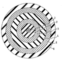
- the construction of the new triax cable with extremely high coupling attenuation with a small diameter ( v 6 mm) and good flexibility as well as a robust design is described in the direction from the inside out.
- the cable consists of an inner conductor 1 made of copper strands 7 x 0.18 silver-plated, ie seven copper wires with a diameter of 0.18 mm, which are silver-plated and twisted together.
- the DC resistance is 100 m ⁇ / m.
- the subsequent dielectric 2 consists of highly insulating material, namely polytetrafluoroethylene, which is extruded onto the inner conductor 1.
- the outer diameter of 1.7 mm corresponds to an insulating material thickness of approximately 0.6 mm. This gives a characteristic impedance of approximately 50 ohms.
- the inner shield 3 comprises three braided shields, which consist of silver-plated copper braid.
- the copper strand is spun in several, for example 16 strands of several, for example 5 or 6 conductors with a diameter of 0.1 mm to form an acute-angled braid.
- the shield 3 has an outer diameter of 3.0 mm and a direct current resistance of 12 m ⁇ / m.
- the inner shield 3 is followed by a second insulation 4. It is also made of extruded polytetrafluoroethylene and has an outer diameter of 3.8 mm.
- the outer shield 5 of the triax cable consists of two braided shields made of silver-plated steel copper wire, which can also achieve a good degree of coverage. 24 beats of 5 or 6 individual conductors with a diameter of 0.13 mm are spun at an acute angle. This results in an outer diameter of 5 mm and a direct current resistance of 17 m ⁇ / m.
- the outer jacket 6 is made of polyurethane. It gives the outside diameter of 6 mm.
- the decisive advantage of the invention lies in the extremely high coupling loss of> 140 dB of the cable. This is achieved through the use of multi-layered umbrellas, which enable a high degree of coverage with low longitudinal resistance and great flexibility.
- the shielding effect relates not only to electrical fields, but also to magnetic fields due to the use of steel copper in the outer shield due to the magnetostatic effect.
- the cable can therefore be used not only for ultrasonic measurements but also in data technology to reduce the sensitivity to interference.
Abstract
Ein konzentrisches Dreileiterkabel umfaßt einen Innenleiter (1) und Außenleiter (3,5) aus geflochtener Litze, die voneinander und von dem Innenleiter (1) durch Isoliermaterial (2,4) distanziert sind. Die Außenleiter (3,5) bestehen jeweils aus mehreren Schichten, deren Gleichstromwiderstand mehrfach kleiner als der des Innenleiters (1 ist. Die Erfindung kommt insbesondere für Kabel für Ultraschallmessungen in Frage.A concentric three-wire cable comprises an inner conductor (1) and outer conductor (3,5) made of braided wire, which are spaced from each other and from the inner conductor (1) by insulating material (2,4). The outer conductors (3, 5) each consist of several layers, the direct current resistance of which is several times smaller than that of the inner conductor (1. The invention is particularly suitable for cables for ultrasonic measurements.
Description
Die Erfindung betrifft ein konzentrisches Dreileiterkabel, insbesondere für Ultraschallmessungen, mit einem Innenleiter und Außenleitern aus geflochtener Litze, die voneinander und von dem Innenleiter durch Isoliermaterial distanziert sind.The invention relates to a concentric three-wire cable, in particular for ultrasound measurements, with an inner conductor and outer conductors made of braided strand, which are spaced from one another and from the inner conductor by insulating material.
Weil vor allem in Kernkraftwerken im Hinblick auf kurze Stillstandszeiten bei wichtigen Prüfungen mit Ultraschall gleichzeitig Reparaturarbeiten stattfinden, die mit Funksprechverkehr verbunden sind oder Lichtbogenschweißen erfordern, ergeben sich recht starke elektrische und/oder elektromagnetische Störfelder. Sie hatten bisher oft zur Folge, daß trotz der Verwendung der oben genannten Dreileiterkabel die Ultraschallprüfungen wegen Störspannungen unterbrochen und zum Beispiel in die Nachtzeiten verlegt werden mußten. Deshalb geht die Erfindung von der Aufgabe aus, durch eine besondere Ausbildung des Kabels die Einkopplung von Störspannungen zu verringern, die Ultraschallmessungen beeinträchtigen können.Because, especially in nuclear power plants with regard to short downtimes, important tests with ultrasound are carried out at the same time as repair work that is connected to radio communication or requires arc welding, there are quite strong electrical and / or electromagnetic interference fields. So far, they have often had the consequence that, despite the use of the three-wire cable mentioned above, the ultrasonic tests had to be interrupted due to interference voltages and, for example, had to be moved to the night. Therefore, the invention is based on the task of reducing the coupling of interference voltages by a special design of the cable, which can impair ultrasonic measurements.
Gemäß der Erfindung ist bei einem Kabel der eingangs genannten Art vorgesehen, daß die Außenleiter jeweils aus mehreren Schichten bestehen und daß ihr Gleichstromwiderstand mehrfach kleiner als der des Innenleiters ist.According to the invention, in the case of a cable of the type mentioned in the introduction, it is provided that the outer conductors each consist of several layers and that their direct current resistance is several times smaller than that of the inner conductor.
Das neue Kabel hat eine extrem hohe Koppeldämpfung.The new cable has an extremely high coupling loss.
Es ist somit unempfindlich gegen die vorgenannten Störeinflüsse. Dennoch kann es mit kleinem Durchmesser und guter Flexibilität ausgebildet werden, wie eingehende Erprobungen gezeigt haben.It is therefore insensitive to the aforementioned interference. Nevertheless, it can be designed with a small diameter and good flexibility, as detailed tests have shown.
Das Widerstandsverhältnis zwischen Außenleitern und Innenleiter kann vorteilhaft 1:5 oder mehr betragen und übersteigt damit erheblich die Werte üblicher Meßkabel, die eine kleinere Koppeldämpfung haben. Dabei sollte der dem Innenleiter benachbarte Außenleiter drei oder mehr Schichten aus geflochtener versilberter Kupferlitze umfassen, die zur Erzielung eines hohen Bedeckungsgrades gegeneinander versetzt sind. Man erreicht damit trotz des erwünschten hohen Bedeckungsgrades eine gute Flexibilität.The resistance ratio between outer conductors and inner conductors can advantageously be 1: 5 or more and thus considerably exceeds the values of conventional measuring cables, which have a lower coupling loss. The outer conductor adjacent to the inner conductor should comprise three or more layers of braided silver-plated copper braid, which are offset from one another to achieve a high degree of coverage. Despite the desired high degree of coverage, good flexibility is achieved.
Die Litze des äußeren Außenleiters besteht dagegen vorzugsweise aus versilbertem Stahlkupferdraht, insbesondere in zwei oder mehr Schichten. Man erreicht damit neben einer elektrischen Abschirmung auch noch eine direkte magnetische Abschirmung, ohne daß die Flexibilität wie bei anderen stahlbewehrten Kabeln beeinträchtigt ist. Dennoch wird auch eine hervorragende mechanische Widerstandsfähigkeit gegen rauhen Betrieb erreicht.In contrast, the strand of the outer outer conductor preferably consists of silver-plated steel copper wire, in particular in two or more layers. In addition to electrical shielding, direct magnetic shielding can also be achieved without the flexibility being impaired, as is the case with other steel-reinforced cables. However, excellent mechanical resistance to rough operation is also achieved.
Das Isoliermaterial kann in bewährter Weise aus Polytetrafluoräthylen bestehen, wobei die Dicke zwischen Innenleiter und erstem Außenleiter abhängig ist von dem geforderten Wellenwiderstand des Kabels. Als äußerer Schutz empfiehlt sich ein Mantel mit annähernd der gleichen Dicke wie das Isoliermaterial. Er besteht zweckmäßig aus Polyurethan, das eingefärbt sein kann, um das Kabel auffälliger zu machen oder zu kennzeichnen.The insulating material can consist of polytetrafluoroethylene, the thickness between the inner conductor and the first outer conductor being dependent on the required characteristic impedance of the cable. A jacket with approximately the same thickness as the insulating material is recommended as external protection. It is suitably made of polyurethane, which can be colored to make the cable more noticeable or to mark it.
Weitere Einzelheiten der Erfindung werden bei der folgenden Beschreibung eines Ausführungsbeispiels anhand der beiliegenden Zeichnung noch näher erläutert, in der ein Kabel nach der Erfindung in einem Querschnitt in größerem Maßstab dargestellt ist.Further details of the invention will be explained in more detail in the following description of an embodiment with reference to the accompanying drawing, in which a cable according to the invention is shown in a cross section on a larger scale.
Der Aufbau des neuen Triaxkabels mit extrem hoher Koppeldämpfung bei kleinem Durchmesser (v 6 mm) und guter Flexibilität sowie robuster Ausführung wird in Richtung von innen nach außen beschrieben. Das Kabel besteht aus einem Innenleiter 1 aus Cu-Litze 7 x 0,18 versilbert, d.h. sieben Kupferdrähten mit 0,18 mm Durchmesser, die versilbert und miteinander verdrillt sind. Der Gleichstromwiderstand ist 100 mΩ/m.The construction of the new triax cable with extremely high coupling attenuation with a small diameter ( v 6 mm) and good flexibility as well as a robust design is described in the direction from the inside out. The cable consists of an inner conductor 1 made of copper strands 7 x 0.18 silver-plated, ie seven copper wires with a diameter of 0.18 mm, which are silver-plated and twisted together. The DC resistance is 100 mΩ / m.
Das nachfolgende Dielektrikum 2 besteht aus hochisolierendem Material, nämlich Polytetrafluoräthylen, das auf den Innenleiter 1 extrudiert ist. Dem Außendurchmesser von 1,7 mm entspricht eine Isoliermaterialdicke von etwa 0,6 mm. Man erhält damit einen Wellenwiderstand von ca. 50 Ohm.The subsequent dielectric 2 consists of highly insulating material, namely polytetrafluoroethylene, which is extruded onto the inner conductor 1. The outer diameter of 1.7 mm corresponds to an insulating material thickness of approximately 0.6 mm. This gives a characteristic impedance of approximately 50 ohms.
Die innere Abschirmung 3 umfaßt drei übereinander geflochtene Schirme, die aus versilberter Kupferlitze bestehen. Die Kupferlitze ist in mehreren, zum Beispiel 16 Schlägen von mehreren, zum Beispiel 5 oder 6 Leitern mit 0,1 mm Durchmesser zu einem spitzwinkligen Geflecht versponnen. Insgesamt ergibt sich für die Abschirmung 3 ein Außendurchmesser von 3,0 mm und ein Gleichstromwiderstand von 12 mΩ/m. Durch diese mehrfachen Abschirmungslagen wird ein sehr guter Bedeckungsgrad bei guter Flexibilität erreicht.The inner shield 3 comprises three braided shields, which consist of silver-plated copper braid. The copper strand is spun in several, for example 16 strands of several, for example 5 or 6 conductors with a diameter of 0.1 mm to form an acute-angled braid. Overall, the shield 3 has an outer diameter of 3.0 mm and a direct current resistance of 12 mΩ / m. These multiple shielding layers achieve a very good degree of coverage with good flexibility.
Der Innenabschirmung 3 folgt eine zweite Isolation 4. Sie besteht ebenfalls aus extrudiertem Polytetrafluoräthylen und hat einen Außendurchmesser von 3,8 mm.The inner shield 3 is followed by a second insulation 4. It is also made of extruded polytetrafluoroethylene and has an outer diameter of 3.8 mm.
Der Außenschirm 5 des Triaxkabels besteht aus zwei übereinander geflochtenen Schirmen aus versilbertem Stahlkupferdraht, die ebenfalls einen guten Bedeckungsgrad erreichen lassen. Dabei sind jeweils 24 Schläge von 5 bzw. 6 Einzelleitern mit 0,13 mm Durchmesser spitzwinklig miteinander versponnen. Dies ergibt einen Außendurchmesser von 5 mm und einen Gleichstromwiderstand von 17 mΩ/m.The
Der äußere Mantel 6 besteht aus Polyurethan. Er ergibt den Außendurchmesser von 6 mm.The outer jacket 6 is made of polyurethane. It gives the outside diameter of 6 mm.
Der entscheidende Vorteil der Erfindung liegt in der extrem hohen Koppeldämpfung von > 140 dB des Kabels. Erreicht wird dies durch die Anwendung mehrschichtiger Schirme, die einen hohen Bedeckungsgrad bei gleichzeitig niedrigem Längswiderstand und großer Flexibilität ermöglichen.The decisive advantage of the invention lies in the extremely high coupling loss of> 140 dB of the cable. This is achieved through the use of multi-layered umbrellas, which enable a high degree of coverage with low longitudinal resistance and great flexibility.
Die Schirmwirkung bezieht sich nicht nur auf elektrische Felder, sondern infolge der Verwendung von Stahlkupfer im äußeren Schirm durch magnetostatische Wirkung auch auf magnetische Felder. Das Kabel ist daher nicht nur bei Ultraschallmessungen sondern auch in der Datentechnik zur Verringerung der Störempfindlichkeit mit Vorteil einsetzbar.The shielding effect relates not only to electrical fields, but also to magnetic fields due to the use of steel copper in the outer shield due to the magnetostatic effect. The cable can therefore be used not only for ultrasonic measurements but also in data technology to reduce the sensitivity to interference.
Claims (8)
dadurch gekennzeichnet ,
daß die Außenleiter (3, 5) jeweils aus mehreren Schichten bestehen und daß ihr Gleichstromwiderstand mehrfach kleiner als der des Innenleiters (1) ist.1. Concentric three-wire cable, in particular for ultrasound measurements, with an inner conductor and outer conductors made of braided strand, which are spaced from one another and from the inner conductor by insulating material,
characterized ,
that the outer conductors (3, 5) each consist of several layers and that their DC resistance is several times smaller than that of the inner conductor (1).
dadurch gekennzeichnet ,
daß das Widerstandsverhältnis 1:5 oder mehr beträgt.2. Cable according to claim 1,
characterized ,
that the resistance ratio is 1: 5 or more.
dadurch gekennzeichnet ,
daß der dem Innenleiter (1) benachbarte Außenleiter (3) drei oder mehr Schichten aus geflochtener versilberter Kupferlitze umfaßt, die zur Erzielung eines hohen Bedeckungsgrades gegeneinander versetzt sind.3. Cable according to claim 1 or 2,
characterized ,
that the inner conductor (1) adjacent outer conductor (3) comprises three or more layers of braided silver-plated copper braid, which are offset from one another to achieve a high degree of coverage.
dadurch gekennzeichnet,
daß die Litze des äußeren Außenleiters (5) aus versilbertem Stahlkupferdraht oder ähnlichem ferromagnetischem Material besteht.4. Cable according to claim 1, 2 or 3,
characterized,
that the strand of the outer outer conductor (5) consists of silver-plated steel copper wire or similar ferromagnetic material.
dadurch gekennzeichnet,
daß das Isoliermaterial (2, 4) aus Polytetrafluoräthylen besteht.5. Cable according to one of claims 1 to 4,
characterized,
that the insulating material (2, 4) consists of polytetrafluoroethylene.
dadurch gekennzeichnet,
daß ein äußerer Mantel (6) aus vorzugsweise eingefärbtem Polyurethan mit mindestens annähernd der gleichen Dicke wie das Isoliermaterial (2,4) vorgesehen ist.6. Cable according to claim 5,
characterized,
that an outer jacket (6) made of preferably colored polyurethane is provided with at least approximately the same thickness as the insulating material (2,4).
dadurch gekennzeichnet,
daß es in der Datentechnik zur Verminderung der Störempfindlichkeit verwendet wird.7. Cable according to claim 1,
characterized,
that it is used in data technology to reduce sensitivity to interference.
dadurch gekennzeichnet,
daß es bei Ultraschallmessungen zur Verminderung der Störempfindlichkeit verwendet wird.8. Cable according to claim 1,
characterized,
that it is used in ultrasonic measurements to reduce sensitivity to interference.
Applications Claiming Priority (2)
| Application Number | Priority Date | Filing Date | Title |
|---|---|---|---|
| DE3428087 | 1984-07-30 | ||
| DE19843428087 DE3428087A1 (en) | 1984-07-30 | 1984-07-30 | CONCENTRIC THREE-WIRE CABLE |
Publications (2)
| Publication Number | Publication Date |
|---|---|
| EP0170159A2 true EP0170159A2 (en) | 1986-02-05 |
| EP0170159A3 EP0170159A3 (en) | 1987-10-07 |
Family
ID=6241940
Family Applications (1)
| Application Number | Title | Priority Date | Filing Date |
|---|---|---|---|
| EP85108920A Ceased EP0170159A3 (en) | 1984-07-30 | 1985-07-16 | Triple conductor concentric cable |
Country Status (7)
| Country | Link |
|---|---|
| US (1) | US4642417A (en) |
| EP (1) | EP0170159A3 (en) |
| JP (1) | JPS6147017A (en) |
| DE (1) | DE3428087A1 (en) |
| DK (1) | DK342885A (en) |
| ES (1) | ES296669Y (en) |
| FI (1) | FI852296L (en) |
Cited By (3)
| Publication number | Priority date | Publication date | Assignee | Title |
|---|---|---|---|---|
| EP2230672A3 (en) * | 2009-03-19 | 2012-06-27 | Sony Corporation | Shielded cable |
| WO2014075780A1 (en) * | 2012-11-13 | 2014-05-22 | Ondal Medical Systems Gmbh | Coaxial cable for the electrical transmission of a radiofrequency and/or high-speed data signal, rotating joint comprising two such coaxial cables, and retaining apparatus comprising at least one such rotating joint |
| CN105719729A (en) * | 2015-01-28 | 2016-06-29 | 深圳金信诺高新技术股份有限公司 | Radio frequency cable internal conductor and half flexible coaxial radio frequency cable |
Families Citing this family (87)
| Publication number | Priority date | Publication date | Assignee | Title |
|---|---|---|---|---|
| JPS62238120A (en) * | 1986-04-07 | 1987-10-19 | Chuo Spring Co Ltd | Control cable and transmission actuating device for automobile using said cable |
| US4868565A (en) * | 1988-01-20 | 1989-09-19 | Schlumberger Technology Corporation | Shielded cable |
| US4965412A (en) * | 1989-04-06 | 1990-10-23 | W. L. Gore & Associates, Inc. | Coaxial electrical cable construction |
| US5043530A (en) * | 1989-07-31 | 1991-08-27 | Champlain Cable Corporation | Electrical cable |
| US5033091A (en) * | 1989-10-12 | 1991-07-16 | Bond Matthew R | Cable interconnection for audio component system |
| CA2045209C (en) * | 1990-06-26 | 1996-02-27 | Toshiaki Yutori | Coaxial cable |
| US5061823A (en) * | 1990-07-13 | 1991-10-29 | W. L. Gore & Associates, Inc. | Crush-resistant coaxial transmission line |
| US5170010A (en) * | 1991-06-24 | 1992-12-08 | Champlain Cable Corporation | Shielded wire and cable with insulation having high temperature and high conductivity |
| US5194838A (en) * | 1991-11-26 | 1993-03-16 | W. L. Gore & Associates, Inc. | Low-torque microwave coaxial cable with graphite disposed between shielding layers |
| US5268534A (en) * | 1992-03-27 | 1993-12-07 | Gailey Brian L | Braided flattened tube conductor |
| US5293001A (en) * | 1992-04-14 | 1994-03-08 | Belden Wire & Cable Company | Flexible shielded cable |
| US5345170A (en) * | 1992-06-11 | 1994-09-06 | Cascade Microtech, Inc. | Wafer probe station having integrated guarding, Kelvin connection and shielding systems |
| US6380751B2 (en) * | 1992-06-11 | 2002-04-30 | Cascade Microtech, Inc. | Wafer probe station having environment control enclosure |
| JP2852847B2 (en) * | 1993-06-04 | 1999-02-03 | 東京特殊電線株式会社 | coaxial cable |
| DE9310993U1 (en) * | 1993-07-22 | 1994-11-17 | Gore W L & Ass Gmbh | Broadband radio frequency-compatible electrical coaxial cable |
| US5457288A (en) * | 1994-02-22 | 1995-10-10 | Olsson; Mark S. | Dual push-cable for pipe inspection |
| US5483020A (en) * | 1994-04-12 | 1996-01-09 | W. L. Gore & Associates, Inc. | Twin-ax cable |
| US5574250A (en) * | 1995-02-03 | 1996-11-12 | W. L. Gore & Associates, Inc. | Multiple differential pair cable |
| US5876326A (en) * | 1995-03-10 | 1999-03-02 | Olympus Optical Co., Ltd. | Electronic endoscope with grounded spirally-wound lead wires |
| US6232789B1 (en) * | 1997-05-28 | 2001-05-15 | Cascade Microtech, Inc. | Probe holder for low current measurements |
| US5561377A (en) * | 1995-04-14 | 1996-10-01 | Cascade Microtech, Inc. | System for evaluating probing networks |
| DE19603215A1 (en) * | 1996-01-30 | 1997-07-31 | Asea Brown Boveri | Busbar system |
| US5914613A (en) * | 1996-08-08 | 1999-06-22 | Cascade Microtech, Inc. | Membrane probing system with local contact scrub |
| US6002263A (en) * | 1997-06-06 | 1999-12-14 | Cascade Microtech, Inc. | Probe station having inner and outer shielding |
| US6091025A (en) | 1997-07-29 | 2000-07-18 | Khamsin Technologies, Llc | Electrically optimized hybird "last mile" telecommunications cable system |
| US6684030B1 (en) | 1997-07-29 | 2004-01-27 | Khamsin Technologies, Llc | Super-ring architecture and method to support high bandwidth digital “last mile” telecommunications systems for unlimited video addressability in hub/star local loop architectures |
| US6246006B1 (en) | 1998-05-01 | 2001-06-12 | Commscope Properties, Llc | Shielded cable and method of making same |
| US6256882B1 (en) | 1998-07-14 | 2001-07-10 | Cascade Microtech, Inc. | Membrane probing system |
| US6239379B1 (en) | 1998-07-29 | 2001-05-29 | Khamsin Technologies Llc | Electrically optimized hybrid “last mile” telecommunications cable system |
| JP2000232957A (en) * | 1999-02-15 | 2000-08-29 | Olympus Optical Co Ltd | Endoscopic device |
| US6578264B1 (en) | 1999-06-04 | 2003-06-17 | Cascade Microtech, Inc. | Method for constructing a membrane probe using a depression |
| US6445202B1 (en) * | 1999-06-30 | 2002-09-03 | Cascade Microtech, Inc. | Probe station thermal chuck with shielding for capacitive current |
| US6838890B2 (en) | 2000-02-25 | 2005-01-04 | Cascade Microtech, Inc. | Membrane probing system |
| US6965226B2 (en) * | 2000-09-05 | 2005-11-15 | Cascade Microtech, Inc. | Chuck for holding a device under test |
| US6914423B2 (en) * | 2000-09-05 | 2005-07-05 | Cascade Microtech, Inc. | Probe station |
| DE10143173A1 (en) | 2000-12-04 | 2002-06-06 | Cascade Microtech Inc | Wafer probe has contact finger array with impedance matching network suitable for wide band |
| SE0100308D0 (en) * | 2001-02-02 | 2001-02-02 | Abb Ab | Induction winding |
| AU2002327490A1 (en) | 2001-08-21 | 2003-06-30 | Cascade Microtech, Inc. | Membrane probing system |
| US6836135B2 (en) * | 2001-08-31 | 2004-12-28 | Cascade Microtech, Inc. | Optical testing device |
| US6777964B2 (en) * | 2002-01-25 | 2004-08-17 | Cascade Microtech, Inc. | Probe station |
| US7352258B2 (en) * | 2002-03-28 | 2008-04-01 | Cascade Microtech, Inc. | Waveguide adapter for probe assembly having a detachable bias tee |
| US6815963B2 (en) * | 2002-05-23 | 2004-11-09 | Cascade Microtech, Inc. | Probe for testing a device under test |
| DE10248821A1 (en) * | 2002-10-19 | 2004-04-29 | Robert Bosch Gmbh | Supply line structure |
| US6847219B1 (en) * | 2002-11-08 | 2005-01-25 | Cascade Microtech, Inc. | Probe station with low noise characteristics |
| US6724205B1 (en) * | 2002-11-13 | 2004-04-20 | Cascade Microtech, Inc. | Probe for combined signals |
| US7250779B2 (en) * | 2002-11-25 | 2007-07-31 | Cascade Microtech, Inc. | Probe station with low inductance path |
| US6861856B2 (en) * | 2002-12-13 | 2005-03-01 | Cascade Microtech, Inc. | Guarded tub enclosure |
| US7221172B2 (en) * | 2003-05-06 | 2007-05-22 | Cascade Microtech, Inc. | Switched suspended conductor and connection |
| US7057404B2 (en) * | 2003-05-23 | 2006-06-06 | Sharp Laboratories Of America, Inc. | Shielded probe for testing a device under test |
| US7492172B2 (en) * | 2003-05-23 | 2009-02-17 | Cascade Microtech, Inc. | Chuck for holding a device under test |
| US7250626B2 (en) * | 2003-10-22 | 2007-07-31 | Cascade Microtech, Inc. | Probe testing structure |
| US6943319B2 (en) * | 2003-11-12 | 2005-09-13 | Msx, Inc | Triaxial heating cable system |
| JP4322638B2 (en) * | 2003-11-20 | 2009-09-02 | 株式会社日立製作所 | Storage device and storage device shielding method |
| US7187188B2 (en) * | 2003-12-24 | 2007-03-06 | Cascade Microtech, Inc. | Chuck with integrated wafer support |
| US7427868B2 (en) * | 2003-12-24 | 2008-09-23 | Cascade Microtech, Inc. | Active wafer probe |
| WO2005121824A2 (en) * | 2004-06-07 | 2005-12-22 | Cascade Microtech, Inc. | Thermal optical chuck |
| US7330041B2 (en) * | 2004-06-14 | 2008-02-12 | Cascade Microtech, Inc. | Localizing a temperature of a device for testing |
| DE202005021386U1 (en) | 2004-07-07 | 2007-11-29 | Cascade Microtech, Inc., Beaverton | Probe with a sensor with membrane suspension |
| EP1628311A1 (en) * | 2004-08-13 | 2006-02-22 | Harada Techno Co. Ltd. | Coaxial Cable |
| US7420381B2 (en) * | 2004-09-13 | 2008-09-02 | Cascade Microtech, Inc. | Double sided probing structures |
| US7535247B2 (en) | 2005-01-31 | 2009-05-19 | Cascade Microtech, Inc. | Interface for testing semiconductors |
| US7656172B2 (en) | 2005-01-31 | 2010-02-02 | Cascade Microtech, Inc. | System for testing semiconductors |
| US20060169897A1 (en) * | 2005-01-31 | 2006-08-03 | Cascade Microtech, Inc. | Microscope system for testing semiconductors |
| JP4865236B2 (en) * | 2005-02-08 | 2012-02-01 | 古河電気工業株式会社 | coaxial cable |
| US7295024B2 (en) * | 2005-02-17 | 2007-11-13 | Xandex, Inc. | Contact signal blocks for transmission of high-speed signals |
| US7449899B2 (en) * | 2005-06-08 | 2008-11-11 | Cascade Microtech, Inc. | Probe for high frequency signals |
| JP5080459B2 (en) * | 2005-06-13 | 2012-11-21 | カスケード マイクロテック インコーポレイテッド | Wideband active / passive differential signal probe |
| US7764072B2 (en) | 2006-06-12 | 2010-07-27 | Cascade Microtech, Inc. | Differential signal probing system |
| US7443186B2 (en) * | 2006-06-12 | 2008-10-28 | Cascade Microtech, Inc. | On-wafer test structures for differential signals |
| US7403028B2 (en) | 2006-06-12 | 2008-07-22 | Cascade Microtech, Inc. | Test structure and probe for differential signals |
| US7723999B2 (en) | 2006-06-12 | 2010-05-25 | Cascade Microtech, Inc. | Calibration structures for differential signal probing |
| US7568946B1 (en) * | 2007-01-16 | 2009-08-04 | Keithley Instruments, Inc. | Triaxial cable with a resistive inner shield |
| US7876114B2 (en) * | 2007-08-08 | 2011-01-25 | Cascade Microtech, Inc. | Differential waveguide probe |
| US7888957B2 (en) * | 2008-10-06 | 2011-02-15 | Cascade Microtech, Inc. | Probing apparatus with impedance optimized interface |
| US8410806B2 (en) | 2008-11-21 | 2013-04-02 | Cascade Microtech, Inc. | Replaceable coupon for a probing apparatus |
| US8319503B2 (en) * | 2008-11-24 | 2012-11-27 | Cascade Microtech, Inc. | Test apparatus for measuring a characteristic of a device under test |
| US9728304B2 (en) * | 2009-07-16 | 2017-08-08 | Pct International, Inc. | Shielding tape with multiple foil layers |
| US20120181059A1 (en) * | 2009-07-24 | 2012-07-19 | Radermacher J Axel | High voltage cable design for electric and hybrid electric vehicles |
| CN102263314A (en) * | 2011-07-12 | 2011-11-30 | 昆山安胜达微波科技有限公司 | High-frequency stationary-phase semisteel radio frequency cable |
| CN102262931A (en) * | 2011-07-12 | 2011-11-30 | 昆山安胜达微波科技有限公司 | Test level cable |
| JP5978509B2 (en) * | 2011-07-25 | 2016-08-24 | 矢崎総業株式会社 | High voltage conductive path and wire harness |
| JP2014143055A (en) * | 2013-01-23 | 2014-08-07 | Nisshin Steel Co Ltd | Coaxial cable having excellent flexibility |
| US20140276066A1 (en) * | 2013-03-12 | 2014-09-18 | Volcano Corporation | Imaging apparatus with reinforced electrical signal transmission member and method of use thereof |
| US10373741B2 (en) * | 2017-05-10 | 2019-08-06 | Creganna Unlimited Company | Electrical cable |
| US11848120B2 (en) | 2020-06-05 | 2023-12-19 | Pct International, Inc. | Quad-shield cable |
| US10950369B1 (en) | 2020-07-20 | 2021-03-16 | Dell Products L.P. | Inverted cable design for high-speed, low loss signal transmission |
| US11894631B2 (en) | 2021-11-24 | 2024-02-06 | Caterpillar Inc. | Concentric conductor |
Citations (3)
| Publication number | Priority date | Publication date | Assignee | Title |
|---|---|---|---|---|
| CA604614A (en) * | 1960-09-06 | Northern Electric Company | Coaxial cable | |
| FR2225817A1 (en) * | 1973-04-13 | 1974-11-08 | Fileca | Multiply-screened coaxial cable has distributed inter-screen impedance - forming lumped series chain with lumped transfer imped as parallel branches |
| US4376920A (en) * | 1981-04-01 | 1983-03-15 | Smith Kenneth L | Shielded radio frequency transmission cable |
Family Cites Families (9)
| Publication number | Priority date | Publication date | Assignee | Title |
|---|---|---|---|---|
| US2376101A (en) * | 1942-04-01 | 1945-05-15 | Ferris Instr Corp | Electrical energy transmission |
| US3163836A (en) * | 1952-04-14 | 1964-12-29 | Sumitomo Electric Industries | Coaxial conductor having parallel connected stranded layers of different pitch for equalizing inductance and current distribution |
| US2669695A (en) * | 1952-09-23 | 1954-02-16 | Breeze Corp | High attenuation shielded lead structure |
| BE534972A (en) * | 1953-03-23 | |||
| US3812283A (en) * | 1971-02-19 | 1974-05-21 | Anaconda Co | Pressure resistant cable |
| US3792409A (en) * | 1973-04-02 | 1974-02-12 | Ransburg Corp | Electrostatic hand gun cable |
| FR2437686A1 (en) * | 1978-09-29 | 1980-04-25 | Mayer Ferdy | LOSS ELECTRIC ELEMENT, SUCH AS WIRE, CABLE AND SCREEN, RESISTANT AND ABSORBENT |
| US4408089A (en) * | 1979-11-16 | 1983-10-04 | Nixon Charles E | Extremely low-attenuation, extremely low radiation loss flexible coaxial cable for microwave energy in the gigaHertz frequency range |
| US4499438A (en) * | 1981-12-07 | 1985-02-12 | Raychem Corporation | High frequency attenuation core and cable |
-
1984
- 1984-07-30 DE DE19843428087 patent/DE3428087A1/en not_active Withdrawn
-
1985
- 1985-06-07 FI FI852296A patent/FI852296L/en not_active Application Discontinuation
- 1985-07-16 EP EP85108920A patent/EP0170159A3/en not_active Ceased
- 1985-07-25 JP JP60165013A patent/JPS6147017A/en active Pending
- 1985-07-25 US US06/759,043 patent/US4642417A/en not_active Expired - Fee Related
- 1985-07-29 DK DK342885A patent/DK342885A/en not_active Application Discontinuation
- 1985-07-30 ES ES1985296669U patent/ES296669Y/en not_active Expired
Patent Citations (3)
| Publication number | Priority date | Publication date | Assignee | Title |
|---|---|---|---|---|
| CA604614A (en) * | 1960-09-06 | Northern Electric Company | Coaxial cable | |
| FR2225817A1 (en) * | 1973-04-13 | 1974-11-08 | Fileca | Multiply-screened coaxial cable has distributed inter-screen impedance - forming lumped series chain with lumped transfer imped as parallel branches |
| US4376920A (en) * | 1981-04-01 | 1983-03-15 | Smith Kenneth L | Shielded radio frequency transmission cable |
Cited By (5)
| Publication number | Priority date | Publication date | Assignee | Title |
|---|---|---|---|---|
| EP2230672A3 (en) * | 2009-03-19 | 2012-06-27 | Sony Corporation | Shielded cable |
| WO2014075780A1 (en) * | 2012-11-13 | 2014-05-22 | Ondal Medical Systems Gmbh | Coaxial cable for the electrical transmission of a radiofrequency and/or high-speed data signal, rotating joint comprising two such coaxial cables, and retaining apparatus comprising at least one such rotating joint |
| CN104782003A (en) * | 2012-11-13 | 2015-07-15 | 欧达尔医疗系统有限责任公司 | Coaxial cable for the electrical transmission of a radiofrequency and/or high-speed data signal, rotating joint comprising two such coaxial cables, and retaining apparatus comprising at least one such rotating joint |
| US9627105B2 (en) | 2012-11-13 | 2017-04-18 | Ondal Medical Systems Gmbh | Coaxial cable for the electrical transmission of a radiofrequency and/or high-speed data signal, rotating joint comprising two such coaxial cables, and retaining apparatus comprising at least one such rotating joint |
| CN105719729A (en) * | 2015-01-28 | 2016-06-29 | 深圳金信诺高新技术股份有限公司 | Radio frequency cable internal conductor and half flexible coaxial radio frequency cable |
Also Published As
| Publication number | Publication date |
|---|---|
| JPS6147017A (en) | 1986-03-07 |
| ES296669U (en) | 1987-12-16 |
| DE3428087A1 (en) | 1986-01-30 |
| FI852296L (en) | 1986-01-31 |
| DK342885A (en) | 1986-01-31 |
| DK342885D0 (en) | 1985-07-29 |
| US4642417A (en) | 1987-02-10 |
| FI852296A0 (en) | 1985-06-07 |
| ES296669Y (en) | 1989-09-01 |
| EP0170159A3 (en) | 1987-10-07 |
Similar Documents
| Publication | Publication Date | Title |
|---|---|---|
| EP0170159A2 (en) | Triple conductor concentric cable | |
| DE3341468C2 (en) | ||
| DE3543106C2 (en) | ||
| DE69937487T2 (en) | CABLE WITH DRILLED CABLE SAVING | |
| EP0619583B1 (en) | Electrical round cable | |
| DE19706753A1 (en) | Flexible and supple cable for handheld medical instruments | |
| DE4214380A1 (en) | TRANSMISSION LINE WITH A FLUID PLEASANT SHEATH | |
| DE2547152A1 (en) | Screened electric cables - provided with PTFE foil unsintered and filled with graphite or carbon fillers for controlled conduction | |
| DE1021042B (en) | Mixture for electrically semiconducting plastic for use in high-voltage high-frequency impulse cables | |
| DE2701233B2 (en) | Shielded power cable | |
| EP1490881B1 (en) | Three-conductor cable | |
| DE3337433A1 (en) | POWER TRANSFER CABLES LIKE SPEAKER CABLES | |
| DE4034548C2 (en) | Automotive windshield antenna for frequencies above the high frequency range | |
| DE914507C (en) | High-voltage cable with a conductor and an overlapping dielectric | |
| DE1046707B (en) | Waveguide transformer | |
| EP0092797B1 (en) | Multi-pole electrical lead | |
| DE3037134A1 (en) | COAXIAL CABLE WITH A BANDPASS FILTER ELEMENT | |
| DE1962316A1 (en) | Electrical line for the transmission of electrical waves | |
| DE3936143A1 (en) | IMPROVED SPEAKER CABLE | |
| DE1085916B (en) | Kryotron, which contains a gate ladder and a control ladder | |
| DE2928727A1 (en) | Termination for medium and high voltage cables - has circular monitoring electrode embedded in insulating ring around conical field control electrode inside insulator | |
| DE2813026A1 (en) | HIGH FREQUENCY TRANSFORMER | |
| DE4312622A1 (en) | Planar heating element on the basis of multiple filaments | |
| DE1900424A1 (en) | Standard setting resistor | |
| DE767806C (en) | High-frequency conductor composed of thin individual conductors |
Legal Events
| Date | Code | Title | Description |
|---|---|---|---|
| PUAI | Public reference made under article 153(3) epc to a published international application that has entered the european phase |
Free format text: ORIGINAL CODE: 0009012 |
|
| AK | Designated contracting states |
Designated state(s): CH DE FR GB IT LI NL SE |
|
| PUAL | Search report despatched |
Free format text: ORIGINAL CODE: 0009013 |
|
| RHK1 | Main classification (correction) |
Ipc: H01B 11/18 |
|
| RAP1 | Party data changed (applicant data changed or rights of an application transferred) |
Owner name: SIEMENS AKTIENGESELLSCHAFT |
|
| AK | Designated contracting states |
Kind code of ref document: A3 Designated state(s): CH DE FR GB IT LI NL SE |
|
| 17P | Request for examination filed |
Effective date: 19871204 |
|
| 17Q | First examination report despatched |
Effective date: 19900402 |
|
| STAA | Information on the status of an ep patent application or granted ep patent |
Free format text: STATUS: THE APPLICATION HAS BEEN REFUSED |
|
| 18R | Application refused |
Effective date: 19901214 |
|
| RIN1 | Information on inventor provided before grant (corrected) |
Inventor name: DORNER, JUERGEN Inventor name: RUTHROF, KLAUS Inventor name: KOERNER, RUDOLF |