EP0168250A2 - Light gauge metal scrap melting system - Google Patents
Light gauge metal scrap melting system Download PDFInfo
- Publication number
- EP0168250A2 EP0168250A2 EP19850304939 EP85304939A EP0168250A2 EP 0168250 A2 EP0168250 A2 EP 0168250A2 EP 19850304939 EP19850304939 EP 19850304939 EP 85304939 A EP85304939 A EP 85304939A EP 0168250 A2 EP0168250 A2 EP 0168250A2
- Authority
- EP
- European Patent Office
- Prior art keywords
- molten metal
- auger
- melting
- scrap
- chamber
- Prior art date
- Legal status (The legal status is an assumption and is not a legal conclusion. Google has not performed a legal analysis and makes no representation as to the accuracy of the status listed.)
- Granted
Links
Images


Classifications
-
- C—CHEMISTRY; METALLURGY
- C22—METALLURGY; FERROUS OR NON-FERROUS ALLOYS; TREATMENT OF ALLOYS OR NON-FERROUS METALS
- C22B—PRODUCTION AND REFINING OF METALS; PRETREATMENT OF RAW MATERIALS
- C22B7/00—Working up raw materials other than ores, e.g. scrap, to produce non-ferrous metals and compounds thereof; Methods of a general interest or applied to the winning of more than two metals
- C22B7/001—Dry processes
- C22B7/003—Dry processes only remelting, e.g. of chips, borings, turnings; apparatus used therefor
-
- Y—GENERAL TAGGING OF NEW TECHNOLOGICAL DEVELOPMENTS; GENERAL TAGGING OF CROSS-SECTIONAL TECHNOLOGIES SPANNING OVER SEVERAL SECTIONS OF THE IPC; TECHNICAL SUBJECTS COVERED BY FORMER USPC CROSS-REFERENCE ART COLLECTIONS [XRACs] AND DIGESTS
- Y02—TECHNOLOGIES OR APPLICATIONS FOR MITIGATION OR ADAPTATION AGAINST CLIMATE CHANGE
- Y02P—CLIMATE CHANGE MITIGATION TECHNOLOGIES IN THE PRODUCTION OR PROCESSING OF GOODS
- Y02P10/00—Technologies related to metal processing
- Y02P10/20—Recycling
-
- Y—GENERAL TAGGING OF NEW TECHNOLOGICAL DEVELOPMENTS; GENERAL TAGGING OF CROSS-SECTIONAL TECHNOLOGIES SPANNING OVER SEVERAL SECTIONS OF THE IPC; TECHNICAL SUBJECTS COVERED BY FORMER USPC CROSS-REFERENCE ART COLLECTIONS [XRACs] AND DIGESTS
- Y10—TECHNICAL SUBJECTS COVERED BY FORMER USPC
- Y10S—TECHNICAL SUBJECTS COVERED BY FORMER USPC CROSS-REFERENCE ART COLLECTIONS [XRACs] AND DIGESTS
- Y10S266/00—Metallurgical apparatus
- Y10S266/901—Scrap metal preheating or melting
Definitions
- the present invention relates generally to the field of remelting metal scrap and specifically to the field of remelting lightweight aluminium scrap such as sheet metal scrap, machine shop turnings, and aluminium beverage cans.
- a primary source of hydrogen and oxygen is the air and fuel gas combination used which is combusted to fire remelting furnaces.
- appropriate steps are taken to minimize the surface areas of reactive scrap metal exposed to reactive gases and means are employed to remove impurities by refining the molten metal with fluxes.
- the combative strategy used to prevent or inhibit the generation of oxides during remelting is generally as follows. Initially, a fluid bath of molten metal is formed in a furnace by remelting high-mass, low-surface area (heavy gauge) materials; then the bath is covered with a protective coating of flux and dross; then additional scrap is remelted by submerging such in the existing molten metal bath. Once the pool of molten metal has been established in the furnace it is brought to a preset level and drained off at a rate which is commensurate with additions of more scrap. The barrier coating which covers the bath is formed by fluxing the surface of the bath. The impurities, aided by the flux, float to the surface to form a crust or "dross" on top of the bath. The dross is in a solid or plastic state.
- skim and dross Directly beneath the dross, is a "skim" of semi-molten, semi-plastic metal which includes varying degrees of impurities.
- the skim and dross are normally removed either continuously or intermittently from the furnace to prevent large buildups, however it is considered beneficial to have some skim and dross on the top of the furnace to act as a barrier to prevent the additional combination of the molten metal underlying it with oxygen and other atmospheric gases.
- the skim and the dross that are removed from the furnace completely solidify and are either discarded or processed to reclaim entrapped metal.
- the melting of scrap metal is an energy intensive process, and additional energy is required to convert and keep the metal scrap in the molten state.
- the form of energy used is heat, generated by an electric or a combustion source.
- the introduction of metal scrap to the heat generating areas is problematic in that great amounts of heat energy are lost both when relatively cold scrap metal is introduced to those heat generating areas and as those heat generating areas are exposed to the colder ambient air during the introduction of the scrap.
- impurities are generated when scrap is melted in intimate contact with fuel gases, combustion gases, and ambient air.
- metal melting furnaces have been redesigned in an attempt to specifically prevent heat loss when the heat generating area is exposed to ambient air, and furthermore to specifically prevent the fuel gases, combustion gases and ambient air from reacting with the melting scrap to form impurities.
- One of the approaches to furnace modification has taken the form of fabricating an additional chamber, or "melting" chamber, exterior to the hearth, out of refractory materials.
- the refractory "walls" separate the burners from the melting chamber. Ports are built through the walls to permit molten metal flow between the melting chamber and the heating chamber. The ports are located below the fluid level normally set for the molten metal.
- the scrap is introduced into the melting chamber where it comes into contact with the molten metal. Using such an approach, the scrap is always secluded from the detrimental effects of the burners and the burners do not lose valuable heat energy to the ambient air.
- Such pumps which are commercially available, are normally made from graphite or other refractory materials which resist deterioration.
- the addition of the molten metal circulation pump to the separate chamber melting furnace system described above enables the melting and the commercial application of this system to the remelting of relatively heavy gauge scrap.
- low-mass, high-surface area (light gauge) metals resulting in increasingly greater quantities of light gauge scrap being available for recycling.
- aluminum for beverage cans there has been a great increase in the use of aluminum for beverage cans. With the remelting of light gauge scrap, additional problems are encountered and new approaches are needed to reduce melt losses to acceptable levels.
- Molten metal is characterized by very high surface tension.
- heavy gauge scrap is dropped into the molten metal and, by gravity, rapidly sinks into the fluid where it melts. Due to the surface tension and the dross and skim on the top of molten metals, it is more difficult to include light gauge scrap into the fluid because of the fact that it tends to "float" for an extended period of time on the surface. Much of the light gauge scrap that is used is lost to oxidation and other chemical reactions as it begins to melt on the surface. It has been recognized that means are needed to quickly overcome the surface tension, thus ways are required to introduce light gauge scrap through the dross and skim into to melt beneath.
- the present invention provides a system for remelting light gauge scrap metals.
- the system includes a remelting furnace which is separated into a heating chamber and a melting chamber. There are no burner means directed at the surface of the molten metal in the melting chamber. Port means are included in a heat resistant separator wall between the heating chamber and the melting chamber which serve to permit the circulation of molten metal from the heating chamber into the melting chamber and then back from the melting chamber into the heating chamber.
- the circulation of the molten metal is provided by molten metal pumping apparatus positioned to direct the flow of molten metal from the heating chamber into the melting chamber.
- Auger means are included within the melting chamber which operate to produce a gravity flow of the surface of the molten metal in the melting chamber, including the light.
- auger 11 is shown in a partially cut-away view.
- Auger 11 comprises three blades 13 and hub 15.
- Auger 11 is generally in the form of an axial flow turbine and each of the three blades is formed as a spiral flute which comprise a spiral section.
- Hub 15 includes a blind bore 17 which is machined with internal threads 19 to accept external matching threads of drive shaft 23. When drive shaft 23 is assembled by threading into hub 15 the assembly is cross-bored 25 and pin 27 is inserted to prevent auger 11 from becoming detached from drive shaft 23 in operation.
- the outer edges 29 of blades 13 are concentrically machined with bore 17 to permit auger 11 to be fitted-into a cylindrical shape.
- Leading edges 31 and trailing edges 33 are machined in parallel planes perpendicular to the outer edges 29 of blades 13.
- the auger 11 requires at least one blade 13 although three are preferable. It is important, however, that the leading edge 31 of each blade 13 extends circumferentially around the outer edge 29 of the auger to the extent that it overlaps the trailing edge 33 of the next adjacent blade 13 as is best shown in Figures 2 and 6. In a situation where a single blade 13 is used, the leading edge 31 of that blade would extend circumferentially around the outer edge 29 of that blade 13 to the extent that it would overlap the trailing edge of that same blade 13.
- an auger drum 35 which is generally a hollow cylindrical section shape, being axially bored and counterbored as shown in that figure.
- Bore 37 is sized to permit drum 35 to be placed over auger 11 as is shown in Figure 5.
- Counterbore 39 is of a lesser size in diameter such that lip 41 is formed. Lip 41 rides on the leading edges 31 of blades 13 as shown in Figure 4.
- Drum 35 is attached to auger 11 by way of refractory cement.
- drum 35 may be cross-bored into the outer edges 29 of auger 11 and a pin inserted, none of which is shown in the drawing figures.
- the combination of auger 11, drive shaft 23 and drum 35, as described hereinabove, are refered to collectively hereinafter as the auger assembly 45.
- FIG. 5 and 6 there is shown an alternative embodiment of the auger assembly of the present invention including a one piece combined auger 11' and drum 35'.
- hub 15' has a bore 37' which extends axially all the way through.
- the bore 37' also includes keyways 47.
- the drive shaft (not shown) is not threaded into hub 15' but, rather, is locked in place by way of keys (not shown) which fit into corresponding keyways in the drive shaft (not shown) and the keyways 47 of hub 15' of Figures 5 and 6, respectively.
- cross-bores 49' may also be used extending through the walls of hub 15' and through the portion of drive shaft 23' which is fitted within the bore 37' of hub 15'.
- the auger assembly is as illustrated and described in regard to Figures 1-4.
- FIGS 7 and 8 show, respectively, an elevational view, in schematic form, of the system of the invention and a plan view, also in schematic form, of the system of the invention.
- Remelting furnace 49 includes a heating chamber 51 and a melting chamber 53. Interposed into and positioned about the center of melting chamber 53 is auger assembly 45 which is rotated by a power drive assembly 55 such as, for example, an electric motor.
- the wall 57 which separates the heating chamber 51 from the melting chamber 53 includes entrance flow port 59 and exit flow port 61.
- Molten metal pump 63 is disposed in heating chamber 51 and positioned such that its operation will produce flow of molten metal into melting chamber 53 through entrance flow port 59 and Lack out of netting chamber 53 into heating chamber 51 through exit flow port 61, followed by a general recirculation of that molten metal back around towards pump 63, as best shown in Figure 8.
- auger assembly 45 is rotated in the direction indicated by arrow 67 in Figure 2.
- the principle of the operation of the auger assembly 45 is that the leading edges 31 come into the first contact with any unit of molten metal and light gauge scrap which are encountered by that auger assembly 45.
- the rotation of auger assembly 45 creates a downwardly spiraled action of the molten metal beneath the surface of the melt.
- the molten metal which is in both melting chamber 53 and the confines of drum 35 flow generally downwardly from auger 11 and into contact with the flow of molten metal which is moving through melting chamber 53 by virtue of the flow created by pump 63.
- the light gauge metal scrap floating on the surface of that metal flows with it by gravity following the path of the fluid as it is spiraled downwardly into the central zone of the melt in melting chamber 53.
- the light metal scrap floating on the surface of that molten metal is physically augered downwardly into the center of the molten metal melt, within the confines of the melting chamber 53, by virtue of the arrangement of the blades 13 of auger 11. The light metal scrap is ultimately forced into contact with the molten metal flowing through melting chamber 53 by virtue of pump 63.
- Auger assembly 45 is positioned relatively near to the molten metal surface 65,_with lip 41 being submerged to the extent necessary to create the gravity flow induced by the downward spiraled flow created by the rotation of auger assembly 45.
- the height of lip 41 in relation to molten metal surface 65 may be varied in relation to the number of revolutions per minute at which auger assembly 45 is rotated.
- Auger assembly 45 is preferably not rotated at a speed which approaches the speed at which substantial quantities of atmospheric gases will be included into the downward spiraled flow of the metal therethrough.
- FIG. 9 An alternate embodiment of the light gauge metal scrap melting system is shown in Figs. 9 and 10.
- auger 11 is used.
- auger drum 69 is merely a hollow cylindrical section shape with a straight inner bore 71 but with no counterbore similar to counterbore 39.
- the inner bore 71 is sized to be slightly larger than the outer edges 29 of blades 13.
- Auger drum 69 is stationarily mounted within melting chamber 53 being fixed to walls 57 by mounting spacers 73 about as shown in Fig. 9.
- Mounting spacers 73 should be made of a refractory or other material which has similar heat resistant properties to those of walls 57.
- Auger drum 69 may be contructed of materials similar to those used for auger drum 35, but may, alternatively, be constructed of refractory or ceramic materials, known to those with skill in the field, with chemical and mechanical properties acceptable for use in high temperature metal melting furnaces.
- auger drum 69 In operation, as auger 11 is rotated, auger drum 69 remains stationary. In all other respects, the operation of the light gauge metal scrap melting system is as been previously described.
Abstract
Description
- The present invention relates generally to the field of remelting metal scrap and specifically to the field of remelting lightweight aluminium scrap such as sheet metal scrap, machine shop turnings, and aluminium beverage cans.
- A major concern of the secondary metal industry is the generation of oxides and gases which become included, entrained or dissolved into the molten metal during the remelting of scrap metal. These oxides are a source of concern in as much as the progeneration of oxides diminishes the proportion of remelted scrap metal which is ultimately marketable as end product. The percent of scrap rendered non-usable because of oxides generated during remelt is termed "melt loss".
- Impurities form during remelting when the extremely reactive liquid metal surface area interfaces with reactive gases such as oxygen and hydrogen. A primary source of hydrogen and oxygen is the air and fuel gas combination used which is combusted to fire remelting furnaces. To combat impurities in the remelting of scrap metals, appropriate steps are taken to minimize the surface areas of reactive scrap metal exposed to reactive gases and means are employed to remove impurities by refining the molten metal with fluxes.
- In the field of remelting scrap metals, the combative strategy used to prevent or inhibit the generation of oxides during remelting is generally as follows. Initially, a fluid bath of molten metal is formed in a furnace by remelting high-mass, low-surface area (heavy gauge) materials; then the bath is covered with a protective coating of flux and dross; then additional scrap is remelted by submerging such in the existing molten metal bath. Once the pool of molten metal has been established in the furnace it is brought to a preset level and drained off at a rate which is commensurate with additions of more scrap. The barrier coating which covers the bath is formed by fluxing the surface of the bath. The impurities, aided by the flux, float to the surface to form a crust or "dross" on top of the bath. The dross is in a solid or plastic state.
- Directly beneath the dross, is a "skim" of semi-molten, semi-plastic metal which includes varying degrees of impurities. The skim and dross are normally removed either continuously or intermittently from the furnace to prevent large buildups, however it is considered beneficial to have some skim and dross on the top of the furnace to act as a barrier to prevent the additional combination of the molten metal underlying it with oxygen and other atmospheric gases. The skim and the dross that are removed from the furnace completely solidify and are either discarded or processed to reclaim entrapped metal.
- The melting of scrap metal is an energy intensive process, and additional energy is required to convert and keep the metal scrap in the molten state. The form of energy used is heat, generated by an electric or a combustion source. The introduction of metal scrap to the heat generating areas is problematic in that great amounts of heat energy are lost both when relatively cold scrap metal is introduced to those heat generating areas and as those heat generating areas are exposed to the colder ambient air during the introduction of the scrap. In addition, impurities are generated when scrap is melted in intimate contact with fuel gases, combustion gases, and ambient air. As a general proposition metal melting furnaces have been redesigned in an attempt to specifically prevent heat loss when the heat generating area is exposed to ambient air, and furthermore to specifically prevent the fuel gases, combustion gases and ambient air from reacting with the melting scrap to form impurities.
- One of the approaches to furnace modification has taken the form of fabricating an additional chamber, or "melting" chamber, exterior to the hearth, out of refractory materials. The refractory "walls" separate the burners from the melting chamber. Ports are built through the walls to permit molten metal flow between the melting chamber and the heating chamber. The ports are located below the fluid level normally set for the molten metal. The scrap is introduced into the melting chamber where it comes into contact with the molten metal. Using such an approach, the scrap is always secluded from the detrimental effects of the burners and the burners do not lose valuable heat energy to the ambient air.
- In attempting to utilize such separate chamber designs for the remelting furnaces, it has been determined that natural convection of the molten metal by itself, through the ports in the walls between the separate chambers, is not adequate to transfer heat at a rate which is sufficient to both maintain the molten metal in the melting chamber in the molten state and to melt the solid phase scrap metal which is being added. Attempts have been made to utilize special refractory compositions which are designed to transfer the heat from the heating chamber into the melting chamber, with limited success, resulting in only relatively small quantities of scrap being successfully added without reducing the melt temperature below acceptable levels. The addition of special molten metal pumps is ultimately required to insure that the temperatures within the melting chambers are maintained high enough so that solidification does not begin to occur.
- Such pumps, which are commercially available, are normally made from graphite or other refractory materials which resist deterioration. The addition of the molten metal circulation pump to the separate chamber melting furnace system described above enables the melting and the commercial application of this system to the remelting of relatively heavy gauge scrap. However, there has been an increasing market use of low-mass, high-surface area (light gauge) metals, resulting in increasingly greater quantities of light gauge scrap being available for recycling. In particular, there has been a great increase in the use of aluminum for beverage cans. With the remelting of light gauge scrap, additional problems are encountered and new approaches are needed to reduce melt losses to acceptable levels.
- Molten metal is characterized by very high surface tension. Generally speaking, in metal remelting furnaces, heavy gauge scrap is dropped into the molten metal and, by gravity, rapidly sinks into the fluid where it melts. Due to the surface tension and the dross and skim on the top of molten metals, it is more difficult to include light gauge scrap into the fluid because of the fact that it tends to "float" for an extended period of time on the surface. Much of the light gauge scrap that is used is lost to oxidation and other chemical reactions as it begins to melt on the surface. It has been recognized that means are needed to quickly overcome the surface tension, thus ways are required to introduce light gauge scrap through the dross and skim into to melt beneath.
- Initially, attempts were made to mechanically push the light gauge scrap under the molten metal surface. Also, attempts have been made to compress the light gauge scrap into large bundles followed by mechanically forcing the large bundle under the molten metal surface. Both of these methods have been unsuccessful due to excessive melt loss and low scrap metal melting and recovery rates. Beyond these initial attempts, improved methods have been developed to introduce the light gauge scrap beneath the molten metal surface in a separate melting chamber type furnace design.
- An example of such an improved system is found in U.S. Patent No. 4,286,985 wherein the molten metal is pumped from the heating chamber and directed into the upper portion of the melting chamber, thus providing both relatively hot molten metal at the upper portion of the molten pool in the melting chamber and creating a tumbling action in that chamber which has the purpose of swirling the scrap on the surface of the melt down into the melt itself.
- Other designs have been introduced which include a variety of pump impeller arrangements designed to be placed ! directly into the melting chamber substantially below the surface level of the molten metal pool. Examples of such designs are found in U.S. Patent Nos. 3,984,234, 4,128,415, and 4,322,245. In all of these designs, the scrap metal floating on the surface of the molten metal is drawn into the center of the molten pool by way of a fluid vortex created by the submerged impeller of the pump in that pool. The pump impellars of such systems serve the additional purpose of circulating the molten metal from the melting chamber into the heating chamber and from the heating chamber back into the melting chamber.
- These systems have proved somewhat successful in that relatively more light gauge metal scrap can be drawn into the melt without exposure to contamination and oxidation as such material is melting. However these systems have not been entirely successful in practice because, when the impellers are driven at a sufficient speed to draw substantially all of the light gauge scrap rapidly down into the molten pool, a severe vortex is created. This severe vortex tends to also draw the surrounding atmospheric gases into the melt by suction. These gases combine readily with the molten metals to form high levels of impurities. This phenomenon is detailed in U.S. Patent 4,322,245 column 4, lines 42-50. Thus there is a need for a system which will positively drive all of the light gauge scrap into the molten metal without inclusion of atmospheric gases and while also providing good molten metal circulation from the heating chamber to the melting chamber.
- The present invention provides a system for remelting light gauge scrap metals. The system includes a remelting furnace which is separated into a heating chamber and a melting chamber. There are no burner means directed at the surface of the molten metal in the melting chamber. Port means are included in a heat resistant separator wall between the heating chamber and the melting chamber which serve to permit the circulation of molten metal from the heating chamber into the melting chamber and then back from the melting chamber into the heating chamber. The circulation of the molten metal is provided by molten metal pumping apparatus positioned to direct the flow of molten metal from the heating chamber into the melting chamber. Auger means are included within the melting chamber which operate to produce a gravity flow of the surface of the molten metal in the melting chamber, including the light. gauge aluminum scrap floating on the surface of that molten metal, downwardly into the portions of the molten metal pool which are below that surface (the central zone at the molten metal pool). Concurrent with the gravity flow, there is produced a mechanical augering which mechanically forces the light gauge scrap metal down into that central zone of the molten metal pool.
- These features, as well as other features of the present invention, will be more completely disclosed and described in the following specification, the accompanying drawings and the appended claims.
-
- Figure 1 illustrates an elevational view of the auger as mounted to a section of the drive shaft with portions cut away.
- Figure 2 illustrates a plan view of the auger as viewed from I-I of Figure 1.
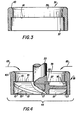
- Figure 3 is an elevational cross-sectional view of the auger drum.
- Figure 4 illustrates the auger assembly including a cross-sectional view of the auger drum and a cut-away view of the auger and drive shaft.
- Figure 5 is an elevational, partly cut-away view of an alternative embodiment of the auger assembly wherein the auger drum and the auger are a single piece.
- Figure 6 is a plan view of the alternate embodiment of the auger assembly as illustrated in Figure 5.
- Figure 7 is an elevational cross-sectional schematic of the light guage metal scrap melting system.
- Figure 8 is a plan view schematic of the light gauge metal scrap melting system.
- Figure 9 is an elevational cross-sectional schematic of an alternate arrangement of the light gauge metal scrap melting system.
- Figure 10 is a plan view schematic of an alternate arrangement of the light gauge metal scrap melting system.
- Referring to Figure 1, auger 11 is shown in a partially cut-away view. Auger 11 comprises three
blades 13 andhub 15. Auger 11 is generally in the form of an axial flow turbine and each of the three blades is formed as a spiral flute which comprise a spiral section.Hub 15 includes ablind bore 17 which is machined withinternal threads 19 to accept external matching threads ofdrive shaft 23. Whendrive shaft 23 is assembled by threading intohub 15 the assembly is cross-bored 25 andpin 27 is inserted to prevent auger 11 from becoming detached fromdrive shaft 23 in operation. - Referring to Figure 2, the
outer edges 29 ofblades 13 are concentrically machined withbore 17 to permit auger 11 to be fitted-into a cylindrical shape. Leadingedges 31 and trailingedges 33 are machined in parallel planes perpendicular to theouter edges 29 ofblades 13. - In the present invention, the auger 11 requires at least one
blade 13 although three are preferable. It is important, however, that the leadingedge 31 of eachblade 13 extends circumferentially around theouter edge 29 of the auger to the extent that it overlaps the trailingedge 33 of the nextadjacent blade 13 as is best shown in Figures 2 and 6. In a situation where asingle blade 13 is used, the leadingedge 31 of that blade would extend circumferentially around theouter edge 29 of thatblade 13 to the extent that it would overlap the trailing edge of thatsame blade 13. - Referring to Figure 3, there is illustrated an
auger drum 35 which is generally a hollow cylindrical section shape, being axially bored and counterbored as shown in that figure.Bore 37 is sized to permitdrum 35 to be placed over auger 11 as is shown in Figure 5.Counterbore 39 is of a lesser size in diameter such thatlip 41 is formed.Lip 41 rides on theleading edges 31 ofblades 13 as shown in Figure 4. - As illustrated in Figures 3 and 4, the upper edge of the drum is machined to
radius 43.Drum 35 is attached to auger 11 by way of refractory cement. Alternatively, drum 35 may be cross-bored into theouter edges 29 of auger 11 and a pin inserted, none of which is shown in the drawing figures. The combination of auger 11,drive shaft 23 anddrum 35, as described hereinabove, are refered to collectively hereinafter as theauger assembly 45. - Referring to Figures 5 and 6 there is shown an alternative embodiment of the auger assembly of the present invention including a one piece combined auger 11' and drum 35'. There is an additional difference in this alternative design in that hub 15' has a bore 37' which extends axially all the way through. Referring to Figure 6, the bore 37' also includes
keyways 47. In this alternative embodiment, the drive shaft (not shown) is not threaded into hub 15' but, rather, is locked in place by way of keys (not shown) which fit into corresponding keyways in the drive shaft (not shown) and thekeyways 47 of hub 15' of Figures 5 and 6, respectively. In addition, cross-bores 49' may also be used extending through the walls of hub 15' and through the portion of drive shaft 23' which is fitted within the bore 37' of hub 15'. In all other respects, the auger assembly is as illustrated and described in regard to Figures 1-4. - Figures 7 and 8 show, respectively, an elevational view, in schematic form, of the system of the invention and a plan view, also in schematic form, of the system of the invention.
Remelting furnace 49 includes aheating chamber 51 and amelting chamber 53. Interposed into and positioned about the center of meltingchamber 53 isauger assembly 45 which is rotated by a power drive assembly 55 such as, for example, an electric motor. Thewall 57 which separates theheating chamber 51 from themelting chamber 53 includesentrance flow port 59 andexit flow port 61.Molten metal pump 63 is disposed inheating chamber 51 and positioned such that its operation will produce flow of molten metal intomelting chamber 53 throughentrance flow port 59 and Lack out of nettingchamber 53 intoheating chamber 51 throughexit flow port 61, followed by a general recirculation of that molten metal back around towardspump 63, as best shown in Figure 8. - In Figure 7. light
gauge metal scrap 65 is shown disposed on the surface of the molten metal pool within meltingchamber 53. The level of themolten metal surface 65 is maintained at an elevational height which is higher thanlip 51 ofauger assembly 45 such that the molten metal in themelting chamber 53 will flow over thelip 41 ofdrum 35 and flow down through thebore 37 thereof. This flow pattern is schematically represented in Figure 4 with the numeral 65 representing the molten metal surface and the direction of gravity flow of the surface area of the molten metal. - In operation,
auger assembly 45 is rotated in the direction indicated byarrow 67 in Figure 2. The principle of the operation of theauger assembly 45, is that the leadingedges 31 come into the first contact with any unit of molten metal and light gauge scrap which are encountered by thatauger assembly 45. The rotation ofauger assembly 45 creates a downwardly spiraled action of the molten metal beneath the surface of the melt. The molten metal which is in both meltingchamber 53 and the confines ofdrum 35, flow generally downwardly from auger 11 and into contact with the flow of molten metal which is moving throughmelting chamber 53 by virtue of the flow created bypump 63. The flow of molten metal produced by the rotation of auger 11 andauger assembly 45 reduces the level of molten metal withinauger assembly 45, above auger 11, as confined bydrum 35. Thus, molten metal from the surrounding portions of meltingchamber 53 flows by way of gravity overlip 41 into the confines ofdrum 35. - As the molten metal flows over
lip 41 ofauger assembly 45 by way of gravity, the light gauge metal scrap floating on the surface of that metal flows with it by gravity following the path of the fluid as it is spiraled downwardly into the central zone of the melt in meltingchamber 53. In addition and concurrently, the light metal scrap floating on the surface of that molten metal is physically augered downwardly into the center of the molten metal melt, within the confines of themelting chamber 53, by virtue of the arrangement of theblades 13 of auger 11. The light metal scrap is ultimately forced into contact with the molten metal flowing throughmelting chamber 53 by virtue ofpump 63. The downward spiraled flow created by the rotation ofauger assembly 45 needs only to be vigorous enough to create a lowering of the surface level of the molten metal within the confines ofdrum 35.Auger assembly 45 is positioned relatively near to themolten metal surface 65,_with lip 41 being submerged to the extent necessary to create the gravity flow induced by the downward spiraled flow created by the rotation ofauger assembly 45. Within the scope of the present invention, the height oflip 41 in relation tomolten metal surface 65 may be varied in relation to the number of revolutions per minute at whichauger assembly 45 is rotated.Auger assembly 45 is preferably not rotated at a speed which approaches the speed at which substantial quantities of atmospheric gases will be included into the downward spiraled flow of the metal therethrough. - An alternate embodiment of the light gauge metal scrap melting system is shown in Figs. 9 and 10. In this alternate embodiment auger 11 is used. However a slightly different design of
auger drum 69 is used in that it is merely a hollow cylindrical section shape with a straight inner bore 71 but with no counterbore similar tocounterbore 39. Theinner bore 71 is sized to be slightly larger than theouter edges 29 ofblades 13.Auger drum 69 is stationarily mounted withinmelting chamber 53 being fixed towalls 57 by mountingspacers 73 about as shown in Fig. 9. Mountingspacers 73 should be made of a refractory or other material which has similar heat resistant properties to those ofwalls 57.Auger drum 69 may be contructed of materials similar to those used forauger drum 35, but may, alternatively, be constructed of refractory or ceramic materials, known to those with skill in the field, with chemical and mechanical properties acceptable for use in high temperature metal melting furnaces. - In operation, as auger 11 is rotated,
auger drum 69 remains stationary. In all other respects, the operation of the light gauge metal scrap melting system is as been previously described.
Claims (13)
Priority Applications (1)
| Application Number | Priority Date | Filing Date | Title |
|---|---|---|---|
| AT85304939T ATE54337T1 (en) | 1984-07-10 | 1985-07-10 | MELTING SYSTEM FOR LIGHT METAL SCRAP. |
Applications Claiming Priority (2)
| Application Number | Priority Date | Filing Date | Title |
|---|---|---|---|
| US06/629,525 US4598899A (en) | 1984-07-10 | 1984-07-10 | Light gauge metal scrap melting system |
| US629525 | 1984-07-10 |
Publications (3)
| Publication Number | Publication Date |
|---|---|
| EP0168250A2 true EP0168250A2 (en) | 1986-01-15 |
| EP0168250A3 EP0168250A3 (en) | 1986-09-17 |
| EP0168250B1 EP0168250B1 (en) | 1990-07-04 |
Family
ID=24523370
Family Applications (1)
| Application Number | Title | Priority Date | Filing Date |
|---|---|---|---|
| EP19850304939 Expired - Lifetime EP0168250B1 (en) | 1984-07-10 | 1985-07-10 | Light gauge metal scrap melting system |
Country Status (9)
| Country | Link |
|---|---|
| US (1) | US4598899A (en) |
| EP (1) | EP0168250B1 (en) |
| JP (1) | JPS6134123A (en) |
| AT (1) | ATE54337T1 (en) |
| AU (1) | AU567222B2 (en) |
| BR (1) | BR8503285A (en) |
| CA (1) | CA1248753A (en) |
| DE (1) | DE3578534D1 (en) |
| NO (1) | NO852756L (en) |
Cited By (26)
| Publication number | Priority date | Publication date | Assignee | Title |
|---|---|---|---|---|
| EP0448724A1 (en) * | 1989-10-14 | 1991-10-02 | Hitachi Metals, Ltd. | Melting apparatus of cutting scrap |
| GB2266896A (en) * | 1992-04-24 | 1993-11-17 | Miyamoto Kogyosho Kk | Process and apparatus for melting aluminium alloy scraps |
| EP2006627A1 (en) * | 2007-06-21 | 2008-12-24 | Paul V. Cooper | Transferring molten metal from one structure to another |
| US8075837B2 (en) | 2003-07-14 | 2011-12-13 | Cooper Paul V | Pump with rotating inlet |
| US8178037B2 (en) | 2002-07-12 | 2012-05-15 | Cooper Paul V | System for releasing gas into molten metal |
| US8361379B2 (en) | 2002-07-12 | 2013-01-29 | Cooper Paul V | Gas transfer foot |
| US8529828B2 (en) | 2002-07-12 | 2013-09-10 | Paul V. Cooper | Molten metal pump components |
| WO2015171399A1 (en) * | 2014-05-09 | 2015-11-12 | Altek L.L.C. | System and method for melting light gauge metal stock |
| US9643247B2 (en) | 2007-06-21 | 2017-05-09 | Molten Metal Equipment Innovations, Llc | Molten metal transfer and degassing system |
| US9657578B2 (en) | 2009-08-07 | 2017-05-23 | Molten Metal Equipment Innovations, Llc | Rotary degassers and components therefor |
| US9855600B2 (en) | 2007-06-21 | 2018-01-02 | Molten Metal Equipment Innovations, Llc | Molten metal transfer system and rotor |
| US9862026B2 (en) | 2007-06-21 | 2018-01-09 | Molten Metal Equipment Innovations, Llc | Method of forming transfer well |
| US9903383B2 (en) | 2013-03-13 | 2018-02-27 | Molten Metal Equipment Innovations, Llc | Molten metal rotor with hardened top |
| US9909808B2 (en) | 2007-06-21 | 2018-03-06 | Molten Metal Equipment Innovations, Llc | System and method for degassing molten metal |
| US9982945B2 (en) | 2007-06-21 | 2018-05-29 | Molten Metal Equipment Innovations, Llc | Molten metal transfer vessel and method of construction |
| US10052688B2 (en) | 2013-03-15 | 2018-08-21 | Molten Metal Equipment Innovations, Llc | Transfer pump launder system |
| US10126058B2 (en) | 2013-03-14 | 2018-11-13 | Molten Metal Equipment Innovations, Llc | Molten metal transferring vessel |
| US10138892B2 (en) | 2014-07-02 | 2018-11-27 | Molten Metal Equipment Innovations, Llc | Rotor and rotor shaft for molten metal |
| US10267314B2 (en) | 2016-01-13 | 2019-04-23 | Molten Metal Equipment Innovations, Llc | Tensioned support shaft and other molten metal devices |
| US10274256B2 (en) | 2007-06-21 | 2019-04-30 | Molten Metal Equipment Innovations, Llc | Vessel transfer systems and devices |
| US10309725B2 (en) | 2009-09-09 | 2019-06-04 | Molten Metal Equipment Innovations, Llc | Immersion heater for molten metal |
| US10428821B2 (en) | 2009-08-07 | 2019-10-01 | Molten Metal Equipment Innovations, Llc | Quick submergence molten metal pump |
| US10947980B2 (en) | 2015-02-02 | 2021-03-16 | Molten Metal Equipment Innovations, Llc | Molten metal rotor with hardened blade tips |
| US11149747B2 (en) | 2017-11-17 | 2021-10-19 | Molten Metal Equipment Innovations, Llc | Tensioned support post and other molten metal devices |
| US11358217B2 (en) | 2019-05-17 | 2022-06-14 | Molten Metal Equipment Innovations, Llc | Method for melting solid metal |
| US11873845B2 (en) | 2021-05-28 | 2024-01-16 | Molten Metal Equipment Innovations, Llc | Molten metal transfer device |
Families Citing this family (41)
| Publication number | Priority date | Publication date | Assignee | Title |
|---|---|---|---|---|
| US4747583A (en) * | 1985-09-26 | 1988-05-31 | Gordon Eliott B | Apparatus for melting metal particles |
| US4685822A (en) * | 1986-05-15 | 1987-08-11 | Union Carbide Corporation | Strengthened graphite-metal threaded connection |
| JP2554510B2 (en) * | 1987-11-17 | 1996-11-13 | 三建産業 株式会社 | Non-ferrous metal chip melting device |
| US4940214A (en) * | 1988-08-23 | 1990-07-10 | Gillespie & Powers, Inc. | Apparatus for generating a vortex in a melt |
| US4884786A (en) * | 1988-08-23 | 1989-12-05 | Gillespie & Powers, Inc. | Apparatus for generating a vortex in a melt |
| US5143357A (en) * | 1990-11-19 | 1992-09-01 | The Carborundum Company | Melting metal particles and dispersing gas with vaned impeller |
| US5268020A (en) * | 1991-12-13 | 1993-12-07 | Claxton Raymond J | Dual impeller vortex system and method |
| US5308045A (en) * | 1992-09-04 | 1994-05-03 | Cooper Paul V | Scrap melter impeller |
| US5597289A (en) * | 1995-03-07 | 1997-01-28 | Thut; Bruno H. | Dynamically balanced pump impeller |
| WO1997026101A1 (en) * | 1996-01-17 | 1997-07-24 | Metaullics Systems Co. L.P. | Improved molten metal charge well |
| JP2796274B2 (en) * | 1996-08-12 | 1998-09-10 | 川崎重工業株式会社 | Melting furnace and melting method |
| US5944496A (en) * | 1996-12-03 | 1999-08-31 | Cooper; Paul V. | Molten metal pump with a flexible coupling and cement-free metal-transfer conduit connection |
| US6036745A (en) * | 1997-01-17 | 2000-03-14 | Metaullics Systems Co., L.P. | Molten metal charge well |
| US5951243A (en) * | 1997-07-03 | 1999-09-14 | Cooper; Paul V. | Rotor bearing system for molten metal pumps |
| US6019576A (en) * | 1997-09-22 | 2000-02-01 | Thut; Bruno H. | Pumps for pumping molten metal with a stirring action |
| US6027685A (en) * | 1997-10-15 | 2000-02-22 | Cooper; Paul V. | Flow-directing device for molten metal pump |
| US6093000A (en) | 1998-08-11 | 2000-07-25 | Cooper; Paul V | Molten metal pump with monolithic rotor |
| US6887425B2 (en) * | 1998-11-09 | 2005-05-03 | Metaullics Systems Co., L.P. | Shaft and post assemblies for molten metal apparatus |
| AU760328B2 (en) | 1998-11-09 | 2003-05-15 | Metaullics Systems Co., L.P. | Shaft and post assemblies for molten metal pumping apparatus |
| EP1522735B1 (en) * | 1998-11-09 | 2006-12-20 | Pyrotek, Inc. | Shaft and post assemblies for molten metal pumping apparatus |
| US6074455A (en) * | 1999-01-27 | 2000-06-13 | Metaullics Systems Co., L.P. | Aluminum scrap melting process and apparatus |
| US6303074B1 (en) | 1999-05-14 | 2001-10-16 | Paul V. Cooper | Mixed flow rotor for molten metal pumping device |
| US6602462B2 (en) * | 1999-09-30 | 2003-08-05 | Alain Renaud Boulet | Auger pump for handling magnesium and magnesium alloys |
| US6689310B1 (en) | 2000-05-12 | 2004-02-10 | Paul V. Cooper | Molten metal degassing device and impellers therefor |
| US6723276B1 (en) | 2000-08-28 | 2004-04-20 | Paul V. Cooper | Scrap melter and impeller |
| US6717026B2 (en) * | 2001-02-27 | 2004-04-06 | Clean Technologies International Corporation | Molten metal reactor utilizing molten metal flow for feed material and reaction product entrapment |
| US7731891B2 (en) | 2002-07-12 | 2010-06-08 | Cooper Paul V | Couplings for molten metal devices |
| US7906068B2 (en) | 2003-07-14 | 2011-03-15 | Cooper Paul V | Support post system for molten metal pump |
| US7453177B2 (en) * | 2004-11-19 | 2008-11-18 | Magnadrive Corporation | Magnetic coupling devices and associated methods |
| US7556766B2 (en) * | 2005-11-15 | 2009-07-07 | Alcoa Inc. | Controlled free vortex scrap ingester and molten metal pump |
| ES2528114T3 (en) | 2006-01-26 | 2015-02-04 | Digimet 2013 Sl | Waste treatment method |
| US20080184848A1 (en) * | 2006-08-23 | 2008-08-07 | La Sorda Terence D | Vapor-Reinforced Expanding Volume of Gas to Minimize the Contamination of Products Treated in a Melting Furnace |
| US20090064821A1 (en) * | 2006-08-23 | 2009-03-12 | Air Liquide Industrial U.S. Lp | Vapor-Reinforced Expanding Volume of Gas to Minimize the Contamination of Products Treated in a Melting Furnace |
| US8613884B2 (en) | 2007-06-21 | 2013-12-24 | Paul V. Cooper | Launder transfer insert and system |
| US8535603B2 (en) | 2009-08-07 | 2013-09-17 | Paul V. Cooper | Rotary degasser and rotor therefor |
| US8449814B2 (en) | 2009-08-07 | 2013-05-28 | Paul V. Cooper | Systems and methods for melting scrap metal |
| US8444911B2 (en) | 2009-08-07 | 2013-05-21 | Paul V. Cooper | Shaft and post tensioning device |
| US8714914B2 (en) | 2009-09-08 | 2014-05-06 | Paul V. Cooper | Molten metal pump filter |
| KR101735425B1 (en) * | 2015-12-14 | 2017-05-16 | (주)디에스리퀴드 | System and method for aluminium black dross recycling |
| CN109642773B (en) | 2016-08-29 | 2020-11-20 | 派瑞泰克有限公司 | Waste immersion device |
| CN216712212U (en) * | 2021-12-20 | 2022-06-10 | 中信戴卡股份有限公司 | Aluminum alloy material smelting device |
Citations (9)
| Publication number | Priority date | Publication date | Assignee | Title |
|---|---|---|---|---|
| US1729631A (en) * | 1921-10-28 | 1929-10-01 | Aluminum Co Of America | Process of reclaiming scrap metals |
| US3276758A (en) * | 1963-04-24 | 1966-10-04 | North American Aviation Inc | Metal melting furnace system |
| DE2140412B2 (en) * | 1970-08-13 | 1974-07-18 | Juan Blas Arnao Sitges Menendez | Refining process for the extraction of zinc from hard zinc, zinc-containing scrap and zinc-containing waste and device for carrying out the process |
| US3873305A (en) * | 1974-04-08 | 1975-03-25 | Aluminum Co Of America | Method of melting particulate metal charge |
| US3984234A (en) * | 1975-05-19 | 1976-10-05 | Aluminum Company Of America | Method and apparatus for circulating a molten media |
| US3997336A (en) * | 1975-12-12 | 1976-12-14 | Aluminum Company Of America | Metal scrap melting system |
| US4128415A (en) * | 1977-12-09 | 1978-12-05 | Aluminum Company Of America | Aluminum scrap reclamation |
| US4286985A (en) * | 1980-03-31 | 1981-09-01 | Aluminum Company Of America | Vortex melting system |
| US4322245A (en) * | 1980-01-09 | 1982-03-30 | Claxton Raymond J | Method for submerging entraining, melting and circulating metal charge in molten media |
Family Cites Families (7)
| Publication number | Priority date | Publication date | Assignee | Title |
|---|---|---|---|---|
| US1522765A (en) * | 1922-12-04 | 1925-01-13 | Metals Refining Company | Apparatus for melting scrap metal |
| US2038221A (en) * | 1935-01-10 | 1936-04-21 | Western Electric Co | Method of and apparatus for stirring materials |
| US2515478A (en) * | 1944-11-15 | 1950-07-18 | Owens Corning Fiberglass Corp | Apparatus for increasing the homogeneity of molten glass |
| US2488447A (en) * | 1948-03-12 | 1949-11-15 | Glenn M Tangen | Amalgamator |
| US3400923A (en) * | 1964-05-15 | 1968-09-10 | Aluminium Lab Ltd | Apparatus for separation of materials from liquid |
| CA1226738A (en) * | 1983-03-14 | 1987-09-15 | Robert J. Ormesher | Metal scrap reclamation system |
| GB8308449D0 (en) * | 1983-03-28 | 1983-05-05 | Alcan Int Ltd | Melting scrap metal |
-
1984
- 1984-07-10 US US06/629,525 patent/US4598899A/en not_active Expired - Lifetime
-
1985
- 1985-06-21 CA CA000484846A patent/CA1248753A/en not_active Expired
- 1985-07-02 AU AU44484/85A patent/AU567222B2/en not_active Ceased
- 1985-07-08 JP JP14845685A patent/JPS6134123A/en active Granted
- 1985-07-09 NO NO852756A patent/NO852756L/en unknown
- 1985-07-09 BR BR8503285A patent/BR8503285A/en not_active IP Right Cessation
- 1985-07-10 AT AT85304939T patent/ATE54337T1/en not_active IP Right Cessation
- 1985-07-10 DE DE8585304939T patent/DE3578534D1/en not_active Expired - Fee Related
- 1985-07-10 EP EP19850304939 patent/EP0168250B1/en not_active Expired - Lifetime
Patent Citations (9)
| Publication number | Priority date | Publication date | Assignee | Title |
|---|---|---|---|---|
| US1729631A (en) * | 1921-10-28 | 1929-10-01 | Aluminum Co Of America | Process of reclaiming scrap metals |
| US3276758A (en) * | 1963-04-24 | 1966-10-04 | North American Aviation Inc | Metal melting furnace system |
| DE2140412B2 (en) * | 1970-08-13 | 1974-07-18 | Juan Blas Arnao Sitges Menendez | Refining process for the extraction of zinc from hard zinc, zinc-containing scrap and zinc-containing waste and device for carrying out the process |
| US3873305A (en) * | 1974-04-08 | 1975-03-25 | Aluminum Co Of America | Method of melting particulate metal charge |
| US3984234A (en) * | 1975-05-19 | 1976-10-05 | Aluminum Company Of America | Method and apparatus for circulating a molten media |
| US3997336A (en) * | 1975-12-12 | 1976-12-14 | Aluminum Company Of America | Metal scrap melting system |
| US4128415A (en) * | 1977-12-09 | 1978-12-05 | Aluminum Company Of America | Aluminum scrap reclamation |
| US4322245A (en) * | 1980-01-09 | 1982-03-30 | Claxton Raymond J | Method for submerging entraining, melting and circulating metal charge in molten media |
| US4286985A (en) * | 1980-03-31 | 1981-09-01 | Aluminum Company Of America | Vortex melting system |
Cited By (69)
| Publication number | Priority date | Publication date | Assignee | Title |
|---|---|---|---|---|
| EP0448724A1 (en) * | 1989-10-14 | 1991-10-02 | Hitachi Metals, Ltd. | Melting apparatus of cutting scrap |
| EP0448724A4 (en) * | 1989-10-14 | 1992-04-22 | Hitachi Metals, Ltd. | Melting apparatus of cutting scrap |
| US5135202A (en) * | 1989-10-14 | 1992-08-04 | Hitachi Metals, Ltd. | Apparatus for melting down chips |
| GB2266896A (en) * | 1992-04-24 | 1993-11-17 | Miyamoto Kogyosho Kk | Process and apparatus for melting aluminium alloy scraps |
| US5385338A (en) * | 1992-04-24 | 1995-01-31 | Miyamoto Kogyosho Co., Ltd. | Apparatus for melting aluminum alloy scraps |
| GB2266896B (en) * | 1992-04-24 | 1995-06-14 | Miyamoto Kogyosho Kk | Process and apparatus for melting aluminium alloy scraps |
| US8110141B2 (en) | 2002-07-12 | 2012-02-07 | Cooper Paul V | Pump with rotating inlet |
| US8440135B2 (en) | 2002-07-12 | 2013-05-14 | Paul V. Cooper | System for releasing gas into molten metal |
| US8178037B2 (en) | 2002-07-12 | 2012-05-15 | Cooper Paul V | System for releasing gas into molten metal |
| US8529828B2 (en) | 2002-07-12 | 2013-09-10 | Paul V. Cooper | Molten metal pump components |
| US8361379B2 (en) | 2002-07-12 | 2013-01-29 | Cooper Paul V | Gas transfer foot |
| US8075837B2 (en) | 2003-07-14 | 2011-12-13 | Cooper Paul V | Pump with rotating inlet |
| US9862026B2 (en) | 2007-06-21 | 2018-01-09 | Molten Metal Equipment Innovations, Llc | Method of forming transfer well |
| US9982945B2 (en) | 2007-06-21 | 2018-05-29 | Molten Metal Equipment Innovations, Llc | Molten metal transfer vessel and method of construction |
| US11759854B2 (en) | 2007-06-21 | 2023-09-19 | Molten Metal Equipment Innovations, Llc | Molten metal transfer structure and method |
| US9643247B2 (en) | 2007-06-21 | 2017-05-09 | Molten Metal Equipment Innovations, Llc | Molten metal transfer and degassing system |
| EP2006627A1 (en) * | 2007-06-21 | 2008-12-24 | Paul V. Cooper | Transferring molten metal from one structure to another |
| US11185916B2 (en) | 2007-06-21 | 2021-11-30 | Molten Metal Equipment Innovations, Llc | Molten metal transfer vessel with pump |
| US9855600B2 (en) | 2007-06-21 | 2018-01-02 | Molten Metal Equipment Innovations, Llc | Molten metal transfer system and rotor |
| US10345045B2 (en) | 2007-06-21 | 2019-07-09 | Molten Metal Equipment Innovations, Llc | Vessel transfer insert and system |
| US11167345B2 (en) | 2007-06-21 | 2021-11-09 | Molten Metal Equipment Innovations, Llc | Transfer system with dual-flow rotor |
| US9909808B2 (en) | 2007-06-21 | 2018-03-06 | Molten Metal Equipment Innovations, Llc | System and method for degassing molten metal |
| US9925587B2 (en) | 2007-06-21 | 2018-03-27 | Molten Metal Equipment Innovations, Llc | Method of transferring molten metal from a vessel |
| US8337746B2 (en) | 2007-06-21 | 2012-12-25 | Cooper Paul V | Transferring molten metal from one structure to another |
| US11130173B2 (en) | 2007-06-21 | 2021-09-28 | Molten Metal Equipment Innovations, LLC. | Transfer vessel with dividing wall |
| US10072891B2 (en) | 2007-06-21 | 2018-09-11 | Molten Metal Equipment Innovations, Llc | Transferring molten metal using non-gravity assist launder |
| US11103920B2 (en) | 2007-06-21 | 2021-08-31 | Molten Metal Equipment Innovations, Llc | Transfer structure with molten metal pump support |
| US11020798B2 (en) | 2007-06-21 | 2021-06-01 | Molten Metal Equipment Innovations, Llc | Method of transferring molten metal |
| US10562097B2 (en) | 2007-06-21 | 2020-02-18 | Molten Metal Equipment Innovations, Llc | Molten metal transfer system and rotor |
| US10195664B2 (en) | 2007-06-21 | 2019-02-05 | Molten Metal Equipment Innovations, Llc | Multi-stage impeller for molten metal |
| US10458708B2 (en) | 2007-06-21 | 2019-10-29 | Molten Metal Equipment Innovations, Llc | Transferring molten metal from one structure to another |
| US10274256B2 (en) | 2007-06-21 | 2019-04-30 | Molten Metal Equipment Innovations, Llc | Vessel transfer systems and devices |
| US10352620B2 (en) | 2007-06-21 | 2019-07-16 | Molten Metal Equipment Innovations, Llc | Transferring molten metal from one structure to another |
| US9657578B2 (en) | 2009-08-07 | 2017-05-23 | Molten Metal Equipment Innovations, Llc | Rotary degassers and components therefor |
| US10428821B2 (en) | 2009-08-07 | 2019-10-01 | Molten Metal Equipment Innovations, Llc | Quick submergence molten metal pump |
| US10570745B2 (en) | 2009-08-07 | 2020-02-25 | Molten Metal Equipment Innovations, Llc | Rotary degassers and components therefor |
| US10309725B2 (en) | 2009-09-09 | 2019-06-04 | Molten Metal Equipment Innovations, Llc | Immersion heater for molten metal |
| US10641279B2 (en) | 2013-03-13 | 2020-05-05 | Molten Metal Equipment Innovations, Llc | Molten metal rotor with hardened tip |
| US11391293B2 (en) | 2013-03-13 | 2022-07-19 | Molten Metal Equipment Innovations, Llc | Molten metal rotor with hardened top |
| US9903383B2 (en) | 2013-03-13 | 2018-02-27 | Molten Metal Equipment Innovations, Llc | Molten metal rotor with hardened top |
| US10302361B2 (en) | 2013-03-14 | 2019-05-28 | Molten Metal Equipment Innovations, Llc | Transfer vessel for molten metal pumping device |
| US10126058B2 (en) | 2013-03-14 | 2018-11-13 | Molten Metal Equipment Innovations, Llc | Molten metal transferring vessel |
| US10126059B2 (en) | 2013-03-14 | 2018-11-13 | Molten Metal Equipment Innovations, Llc | Controlled molten metal flow from transfer vessel |
| US10052688B2 (en) | 2013-03-15 | 2018-08-21 | Molten Metal Equipment Innovations, Llc | Transfer pump launder system |
| US10322451B2 (en) | 2013-03-15 | 2019-06-18 | Molten Metal Equipment Innovations, Llc | Transfer pump launder system |
| US10307821B2 (en) | 2013-03-15 | 2019-06-04 | Molten Metal Equipment Innovations, Llc | Transfer pump launder system |
| WO2015171399A1 (en) * | 2014-05-09 | 2015-11-12 | Altek L.L.C. | System and method for melting light gauge metal stock |
| US9803922B2 (en) | 2014-05-09 | 2017-10-31 | Altek L.L.C. | System and method for melting light gauge scrap |
| US11286939B2 (en) | 2014-07-02 | 2022-03-29 | Molten Metal Equipment Innovations, Llc | Rotor and rotor shaft for molten metal |
| US10138892B2 (en) | 2014-07-02 | 2018-11-27 | Molten Metal Equipment Innovations, Llc | Rotor and rotor shaft for molten metal |
| US10465688B2 (en) | 2014-07-02 | 2019-11-05 | Molten Metal Equipment Innovations, Llc | Coupling and rotor shaft for molten metal devices |
| US11939994B2 (en) | 2014-07-02 | 2024-03-26 | Molten Metal Equipment Innovations, Llc | Rotor and rotor shaft for molten metal |
| US10947980B2 (en) | 2015-02-02 | 2021-03-16 | Molten Metal Equipment Innovations, Llc | Molten metal rotor with hardened blade tips |
| US11933324B2 (en) | 2015-02-02 | 2024-03-19 | Molten Metal Equipment Innovations, Llc | Molten metal rotor with hardened blade tips |
| US10267314B2 (en) | 2016-01-13 | 2019-04-23 | Molten Metal Equipment Innovations, Llc | Tensioned support shaft and other molten metal devices |
| US10641270B2 (en) | 2016-01-13 | 2020-05-05 | Molten Metal Equipment Innovations, Llc | Tensioned support shaft and other molten metal devices |
| US11098719B2 (en) | 2016-01-13 | 2021-08-24 | Molten Metal Equipment Innovations, Llc | Tensioned support shaft and other molten metal devices |
| US11098720B2 (en) | 2016-01-13 | 2021-08-24 | Molten Metal Equipment Innovations, Llc | Tensioned rotor shaft for molten metal |
| US11519414B2 (en) | 2016-01-13 | 2022-12-06 | Molten Metal Equipment Innovations, Llc | Tensioned rotor shaft for molten metal |
| US11149747B2 (en) | 2017-11-17 | 2021-10-19 | Molten Metal Equipment Innovations, Llc | Tensioned support post and other molten metal devices |
| US11358216B2 (en) | 2019-05-17 | 2022-06-14 | Molten Metal Equipment Innovations, Llc | System for melting solid metal |
| US11759853B2 (en) | 2019-05-17 | 2023-09-19 | Molten Metal Equipment Innovations, Llc | Melting metal on a raised surface |
| US11858037B2 (en) | 2019-05-17 | 2024-01-02 | Molten Metal Equipment Innovations, Llc | Smart molten metal pump |
| US11858036B2 (en) | 2019-05-17 | 2024-01-02 | Molten Metal Equipment Innovations, Llc | System and method to feed mold with molten metal |
| US11931803B2 (en) | 2019-05-17 | 2024-03-19 | Molten Metal Equipment Innovations, Llc | Molten metal transfer system and method |
| US11931802B2 (en) | 2019-05-17 | 2024-03-19 | Molten Metal Equipment Innovations, Llc | Molten metal controlled flow launder |
| US11471938B2 (en) | 2019-05-17 | 2022-10-18 | Molten Metal Equipment Innovations, Llc | Smart molten metal pump |
| US11358217B2 (en) | 2019-05-17 | 2022-06-14 | Molten Metal Equipment Innovations, Llc | Method for melting solid metal |
| US11873845B2 (en) | 2021-05-28 | 2024-01-16 | Molten Metal Equipment Innovations, Llc | Molten metal transfer device |
Also Published As
| Publication number | Publication date |
|---|---|
| BR8503285A (en) | 1986-04-01 |
| EP0168250A3 (en) | 1986-09-17 |
| NO852756L (en) | 1986-01-13 |
| EP0168250B1 (en) | 1990-07-04 |
| AU4448485A (en) | 1986-01-16 |
| ATE54337T1 (en) | 1990-07-15 |
| US4598899A (en) | 1986-07-08 |
| JPS6134123A (en) | 1986-02-18 |
| DE3578534D1 (en) | 1990-08-09 |
| CA1248753A (en) | 1989-01-17 |
| JPH0432132B2 (en) | 1992-05-28 |
| AU567222B2 (en) | 1987-11-12 |
Similar Documents
| Publication | Publication Date | Title |
|---|---|---|
| US4598899A (en) | Light gauge metal scrap melting system | |
| EP1070149B1 (en) | Metal scrap submergence system for scrap charging/melting well of furnace | |
| US6074455A (en) | Aluminum scrap melting process and apparatus | |
| US8449814B2 (en) | Systems and methods for melting scrap metal | |
| EP2839232B1 (en) | Molten metal scrap submergence apparatus | |
| KR850000876B1 (en) | Apparatus for refining molten metal | |
| JPH06511461A (en) | melting equipment | |
| US4518424A (en) | Metal scrap reclamation system | |
| US4486228A (en) | Metal scrap reclamation system | |
| CN211177920U (en) | Sainuo top-blown furnace | |
| EP0119094B1 (en) | Metal scrap reclamation system | |
| CN105986130A (en) | Tin slag reduction device | |
| US4356033A (en) | Process for refining metals by drossing procedures | |
| RU2806567C1 (en) | Device for dipping scrap and mixing molten metal in a furnace and system for processing molten metal | |
| US20230055448A1 (en) | Mechanical auger recirculation well | |
| RU2238990C1 (en) | Device for degassing and refining melts of metals and their alloys (versions) | |
| US20230037016A1 (en) | Molten lead scrap submergence apparatus | |
| CN115461587A (en) | Waste immersion device and molten metal recovery system | |
| NO772138L (en) | PROCEDURES FOR REFINING MELTED METAL | |
| RU30751U1 (en) | Device for degassing and refining molten metals and their alloys (options) | |
| Gallo et al. | Forced Circulation and Molten Transfer for Aluminum Melting Furnaces-The 357 Concept | |
| JPH1030884A (en) | Crucible furnace type aluminum melting equipment | |
| US20180017329A1 (en) | Vortex well inerting | |
| JPH10318680A (en) | Crucible and crucible furnace | |
| KR900003348Y1 (en) | Machine for treatmeting of al ash |
Legal Events
| Date | Code | Title | Description |
|---|---|---|---|
| PUAI | Public reference made under article 153(3) epc to a published international application that has entered the european phase |
Free format text: ORIGINAL CODE: 0009012 |
|
| AK | Designated contracting states |
Designated state(s): AT BE CH DE FR GB IT LI LU NL SE |
|
| PUAL | Search report despatched |
Free format text: ORIGINAL CODE: 0009013 |
|
| AK | Designated contracting states |
Kind code of ref document: A3 Designated state(s): AT BE CH DE FR GB IT LI LU NL SE |
|
| 17P | Request for examination filed |
Effective date: 19870216 |
|
| 17Q | First examination report despatched |
Effective date: 19880505 |
|
| RAP1 | Party data changed (applicant data changed or rights of an application transferred) |
Owner name: STEMCOR CORPORATION |
|
| GRAA | (expected) grant |
Free format text: ORIGINAL CODE: 0009210 |
|
| AK | Designated contracting states |
Kind code of ref document: B1 Designated state(s): AT BE CH DE FR GB IT LI LU NL SE |
|
| REF | Corresponds to: |
Ref document number: 54337 Country of ref document: AT Date of ref document: 19900715 Kind code of ref document: T |
|
| REF | Corresponds to: |
Ref document number: 3578534 Country of ref document: DE Date of ref document: 19900809 |
|
| ET | Fr: translation filed | ||
| ITF | It: translation for a ep patent filed |
Owner name: STUDIO ING. ALFREDO RAIMONDI |
|
| BERE | Be: lapsed |
Owner name: STEMCOR CORP. Effective date: 19900731 |
|
| PLBE | No opposition filed within time limit |
Free format text: ORIGINAL CODE: 0009261 |
|
| STAA | Information on the status of an ep patent application or granted ep patent |
Free format text: STATUS: NO OPPOSITION FILED WITHIN TIME LIMIT |
|
| 26N | No opposition filed | ||
| ITTA | It: last paid annual fee | ||
| PGFP | Annual fee paid to national office [announced via postgrant information from national office to epo] |
Ref country code: NL Payment date: 19930731 Year of fee payment: 9 |
|
| PGFP | Annual fee paid to national office [announced via postgrant information from national office to epo] |
Ref country code: GB Payment date: 19930806 Year of fee payment: 9 |
|
| PGFP | Annual fee paid to national office [announced via postgrant information from national office to epo] |
Ref country code: FR Payment date: 19930808 Year of fee payment: 9 |
|
| PGFP | Annual fee paid to national office [announced via postgrant information from national office to epo] |
Ref country code: AT Payment date: 19930820 Year of fee payment: 9 |
|
| PGFP | Annual fee paid to national office [announced via postgrant information from national office to epo] |
Ref country code: SE Payment date: 19930824 Year of fee payment: 9 Ref country code: CH Payment date: 19930824 Year of fee payment: 9 |
|
| PGFP | Annual fee paid to national office [announced via postgrant information from national office to epo] |
Ref country code: DE Payment date: 19930825 Year of fee payment: 9 |
|
| PGFP | Annual fee paid to national office [announced via postgrant information from national office to epo] |
Ref country code: LU Payment date: 19931001 Year of fee payment: 9 |
|
| PGFP | Annual fee paid to national office [announced via postgrant information from national office to epo] |
Ref country code: BE Payment date: 19931028 Year of fee payment: 9 |
|
| EPTA | Lu: last paid annual fee | ||
| PG25 | Lapsed in a contracting state [announced via postgrant information from national office to epo] |
Ref country code: LU Free format text: LAPSE BECAUSE OF NON-PAYMENT OF DUE FEES Effective date: 19940710 Ref country code: GB Effective date: 19940710 Ref country code: AT Effective date: 19940710 |
|
| PG25 | Lapsed in a contracting state [announced via postgrant information from national office to epo] |
Ref country code: SE Effective date: 19940711 |
|
| PG25 | Lapsed in a contracting state [announced via postgrant information from national office to epo] |
Ref country code: LI Effective date: 19940731 Ref country code: CH Effective date: 19940731 Ref country code: BE Effective date: 19940731 |
|
| BERE | Be: lapsed |
Owner name: STEMCOR CORP. Effective date: 19940731 |
|
| EUG | Se: european patent has lapsed |
Ref document number: 85304939.3 Effective date: 19950210 |
|
| PG25 | Lapsed in a contracting state [announced via postgrant information from national office to epo] |
Ref country code: NL Effective date: 19950201 |
|
| GBPC | Gb: european patent ceased through non-payment of renewal fee |
Effective date: 19940710 |
|
| NLV4 | Nl: lapsed or anulled due to non-payment of the annual fee | ||
| PG25 | Lapsed in a contracting state [announced via postgrant information from national office to epo] |
Ref country code: FR Effective date: 19950331 |
|
| REG | Reference to a national code |
Ref country code: CH Ref legal event code: PL |
|
| PG25 | Lapsed in a contracting state [announced via postgrant information from national office to epo] |
Ref country code: DE Effective date: 19950401 |
|
| EUG | Se: european patent has lapsed |
Ref document number: 85304939.3 |
|
| REG | Reference to a national code |
Ref country code: FR Ref legal event code: ST |