EP0167166A2 - Method of providing raster information for a graphics display - Google Patents
Method of providing raster information for a graphics display Download PDFInfo
- Publication number
- EP0167166A2 EP0167166A2 EP85108294A EP85108294A EP0167166A2 EP 0167166 A2 EP0167166 A2 EP 0167166A2 EP 85108294 A EP85108294 A EP 85108294A EP 85108294 A EP85108294 A EP 85108294A EP 0167166 A2 EP0167166 A2 EP 0167166A2
- Authority
- EP
- European Patent Office
- Prior art keywords
- graphics
- display
- band
- identification
- list
- Prior art date
- Legal status (The legal status is an assumption and is not a legal conclusion. Google has not performed a legal analysis and makes no representation as to the accuracy of the status listed.)
- Granted
Links
Images


Classifications
-
- G—PHYSICS
- G06—COMPUTING; CALCULATING OR COUNTING
- G06K—GRAPHICAL DATA READING; PRESENTATION OF DATA; RECORD CARRIERS; HANDLING RECORD CARRIERS
- G06K15/00—Arrangements for producing a permanent visual presentation of the output data, e.g. computer output printers
- G06K15/02—Arrangements for producing a permanent visual presentation of the output data, e.g. computer output printers using printers
- G06K15/10—Arrangements for producing a permanent visual presentation of the output data, e.g. computer output printers using printers by matrix printers
-
- G—PHYSICS
- G06—COMPUTING; CALCULATING OR COUNTING
- G06K—GRAPHICAL DATA READING; PRESENTATION OF DATA; RECORD CARRIERS; HANDLING RECORD CARRIERS
- G06K2215/00—Arrangements for producing a permanent visual presentation of the output data
- G06K2215/0002—Handling the output data
- G06K2215/0062—Handling the output data combining generic and host data, e.g. filling a raster
- G06K2215/0065—Page or partial page composition
Definitions
- the present invention relates to a method of providing pixel information for a hard copy graphics presentation, and particularly to such a method requiring a minimum bit map memory space and operating in conjunction with a hard copy device to avoid delay in providing raster information.
- the information relative to objects for display may be received as a series of high level commands, each indicating the type of graphics object to be displayed and its position.
- Such command may indicate a line is to be drawn including the origin of the line and its length in x and y coordinates.
- the graphics device then typically "pixelates” this information or “draws” elemental or dot portions of the line for entry into a pixel bit map memory.
- the pixel bit map memory is scanned or read out to provide an eventual display, using an ink jet copier or the like.
- bit map is ordinarily calculated or written before the presentation of each strip in order to be responsive to the graphics commands received.
- bit map may be determined again and again, but only successive strips of the bit map would actually be "laid in” to the bit map memory. This involves considerable computing capability to provide the repeated bit map information.
- the commands from a processor or the like which describe graphics objects to be written in a display, are placed in a display list, and the display list is divided into band sublists corresponding to narrow strips or bands of a display.
- the display list is divided into band sublists corresponding to narrow strips or bands of a display.
- the graphics objects are pixelated within a band until it is determined that a particular object crosses from such band to a next band. For crossing objects, a separate crossing list is formed, linking objects into a further band, and this crossing list is merged with the band sublist of such further band whereby the crossing objects, and objects beginning in the further band, can be later pixelated.
- graphics may be input on a fairly high level basis and pixelated piecemeal for strip output allowing the use of a much smaller bit map memory than heretofore required, and allowing the initiation of a printing operation prior to the pixelation of the total display.
- a graphics display which is composed of a multiplicity of dots or "pixels" ,2, disposed in rows such as row 3.
- the rows are "drawn" or imprinted by a means indicated at 4 which may correspond to the electron beam in a cathode-ray-tube, but which in the case of a hard copy printer may correspond to an ink jet or a plurality of ink jets for imprinting individual dots or pixels.
- the number of pixels is actually substantially greater than in the illustration, typically numbering 4,000 pixels for the long dimension of the display by 2,000 pixels for the narrower dimension, and the pixels may be imprinted in various colors or combinations of colors.
- Such a display is typically computer generated, i.e. is formed in response to a plurality of high level commands which specify the graphics object or objects to be printed.
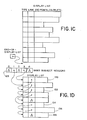
- a command is shown which comprises the designation for a straight line on the display.
- the numbers Xl and Y1 indicate the origin of the line, while Delta X and Delta Y indicate the x and y length components of the line, as further depicted by line 125 in Fig. 11.
- Other information in the command suitably comprises the type of graphics object, e.g. line, panel, character, rectangle, or the like.
- the link field will be hereinafter more fully described.
- the style field may indicate whether the line is dashed or not, the width field specifies the thickness of the line, and the color pattern field identifies the color of the line.
- the specific software for drawing a line or similar object on a screen or copier in response to a command is well known to those skilled in the art.
- Fig. 1B illustrates a graphics system to which the present invention pertains and includes a processor 5 coupled by an address bus and a data bus, 9a and 9b respectively, to processor memory 6.
- the processor in a specific instance was a type 68000.
- a bit map memory comprising a first portion 7a and a second portion 7b that are utilized alternatively to cause ink jet printer 8 to write strips or bands of the display, for example the bands as illustrated in Fig. 1G.
- band or strip pixel information is alternately written into bit map memory portions 7a and 7b. While one section of the bit map memory is read out into the ink jet printer apparatus, the other section is receiving pixel information from the processor.
- the processor operates in two passes. First, all the graphics commands are received and listed. The list is subdivided into band sublists which correspond to tne bands or strips of the display. Then in a second pass, rather than pixelate the entire picture at once (which would require an enormous memory map), pixelation occurs for just one strip or band at a time. In the specific example, a strip comprised thirty-two lines such as pixel line 3 in Fig. lA, out of a total of about 2,000 lines.
- Each band sublist of the overall display list contains the graphic objects (commands similar to that shown in Fig. 11) which begin in a particular band. For example if a line begins in band 10 and continues to band 15, then it is contained only in the band 10 sublist. For the determination of which sublist into which a given graphics object is to be inserted, the lowest X value of the object is determined and the object is sorted into the sublist corresponding thereto.
- the pixelation is driven by a band sublist.
- the graphics objects are fetched from the list one at a time, and pixelated into the bit map memory.
- a draw line routine may be employed which would require the end point and the length of the line.
- the line is clipped if it extends beyond the current band, and for this purpose, the starting and ending values for the given band are also fetched.
- a display list is illustrated schematically in Fig. 1C.
- the sequential ordering implies precedence, with objects being "drawn over" other objects which preceed them in the sequential list.
- the display list contains plural sublists, for example the band sublists for the separate bands to be pixelated and imprinted as hereinbefore mentioned.
- Each graphics object command in the list has a link field, in addition to the other graphics fields, wherein this link field enables the particular graphics object to be linked into a sublist.
- the end of display list pointer points to the last graphics object in the display list. At the time the graphics object in inserted into the display list (during the first pass), it is also linked into one of the band lists, and exactly one band list, namely the list corresponding to the band where the particular graphics object starts.
- band sublist header 1 starts each of the sublists, i.e. an individual header may point to a particular graphics object which is linked with further graphics objects to form a list.
- band sublist header 3 in Fig. 1D points to graphics object 130 which designates, in its link field, the graphics object 132.
- graphics object 132 is linked to objects 134, 136, and 138 in order.
- band sublist header 1 similarly starts a second sublist.
- the display list 140 is further provided with "current" pointers 142 for the band sublists.
- a current pointer exists for each of the band sublists and these pointers are here shown pointing to the end of each sublist.
- the header will start each band sublist, and the current band pointer will move along, pointing to the "next" object.
- crossing headers and pointers are employed for managing the crossover of a graphic from one band to another.
- These headers and pointers pertain to crossing sublists, namely a cross-out sublist and a cross-in sublist. These crossing sublists are designated relative to the band that is being considered at a given time.
- a cross-out sublist indicates graphics objects that are going on to the next band
- a cross-in sublist indicates graphics objects coming from a previous band.
- a graphics object may be deleted from a band sublist and inserted into either of these crossing sublists, with a given graphics object residing at one time in only one sublist.
- a crossing list like the band sublists, is wholly contained in the display list and operation thereof is hereinafter more fully described in connection with the actual procedure.
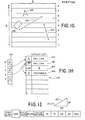
- FIG. 1G illustrating the overall organization of the graphics display to be presented, such graphics display is divided, for purposes of illustration, into nine bands which are numbered 0 to 8 along the "X" axis, i.e. the shorter axis of the display.
- the display is provided to the printer, piecemeal, as each of the bands are first entered into one of the pixel bit map memory sections 7a, 7b and then output to the printer.
- the X direction of the display is actually about 2,000 pixels and the Y direction of the display is actually about 4,000 pixels in a specific example, and the display is divided into bands of thirty-two scan lines each.
- the illustration of the display in Fig. 1G is divided into nine bands merely for ease of illustration.
- Four graphics objects are to be placed in the display of Fig. 1G, a straight line 144, a straight line 146, a rectangle or area 148, and a character 150.
- Band header array 154 contains one entry or pointer for each of the bands.
- the header for band 0 is NIL since no graphics object exists in band 0.
- the header for band 1, on the other hand, points to graphics object 144.
- the link field of graphics object 144 is NIL because no other graphics object starts in band 1.
- the band header for band 2 is NIL inasmuch as no graphics object starts in band 2.
- the band header for band 3 points to graphics object 146 in the display list since this graphics object starts in band 3, while the link field for object 146 points to graphics object 148 on the display list, thereby forming a band sublist including graphics objects 146 and 148.
- the band header for band 6 will point to graphics object 150.
- a header pointer points to the start of each band sublist.
- a line for example line 144
- a crossing list which means a cross-out pointer is set to point to graphics object 144.
- a crossing list now contains one item, i.e. graphics object 144.
- band 2 is indicated as empty so far as its band sublist is concerned, but a merge is done with the graphics object that crossed in, i.e. line 144. If other objects were contained in the band sublist for band 2, they would be merged in and pixelated into the bit map.
- the band sublist includes two items, line 146 and rectangle 148, and the crossing list also includes one item, i.e. line 144. Therefore these three items are pixelated into the bit map for band 3. As we exit band 3, two items are added to the crossing list, namely line 146 and rectangle 148.
- one object is in one list only.
- the object may be broken out of one list, i.e. the band sublist, and placed into another list, i.e. the crossing list, but it will only occur in one list at a time.
- the crossing list and the band sublist will point at two different places in the display list, and so both pointers are followed, always doing whatever occurs first physically in the display list.
- the display list being a sequential list, dictates the precedence.
- the crossing list and the band list together describe the objects that are actually active (that is the object or objects in the particular band).
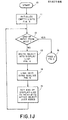
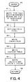
- the program starts at 10 and initializes empty lists in block 11, i.e. for setting the lists to an empty condition (further described in connection with Fig. 3). Thereafter, decision block 12 is entered and if the input (e.g. from a host processor) has ended, the program proceeds to the second pass of the program (Fig.2). Otherwise the next graphics object is written into a display list in block 13 (further described in Fig. 4). In block 14 the particular graphics object is linked into a band sublist (Fig. 5). After block 14, the end of display 'list pointer in Fig. 1C is advanced to the next byte after the object just added to indicate where available memory is. This corresponds to the end of the display list. The procedure continues receiving input information and placing the information into memory.
- the procedure is entered at 30, and in block 31 the end of display list pointer (as illustrated in Fig. 1C) is set to the first byte of the display list.
- the header (128 in Fig. 1D) is set to NIL for each band
- the current band pointer (142 in Fig lE) is set to the band header for each band.
- the object is written into the display list as illustrated in.Fig. 4.
- the type field for the graphics object is written, then the link field, color field, endpoint field, and the Delta X and Delta Y fields in blocks 42 through 45.
- the program of Fig. 5 is then entered at 50 to link the object into a band sublist.
- the "leftmost" coordinate of the graphics object (the lowest X coordinate thereof) is determined.
- the "bandnum" (band number) is set equal to the lowest value of X from block 51 divided by the number of scan lines per band, thirty-two in the present example. This results in the selection of the particular band in which this object starts.
- the link field of the object pointed to by the current band pointer is set to point to the end of display list pointer.
- the link of the last object in this band is set to point to the new object, i.e. the pointer is set to the object that is about to be added.
- the current band pointer is set to point to the end of display list or the location where another object will be added. The procedure of Fig. 1J is continued until all of the graphics objects have been added to the display list.
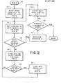
- the second pass which is called scan conversion or pixelation, is entered at 20.
- the band sublists are reset to the front of the list in block 21.
- Reference Fig. 6. This involves the setting of various pointers such as next primitive, cross-in and cross-out as further described in connection with Fig. 6.
- a value is assigned to the next object pointer as further described in Fig. 8.
- decision block 23 if the next object pointer is equal to NIL, block 28 is entered and bandnum, or the number of current band, is advanced by one. If the band number is greater that the total number of bands, the routine is completed. If it is not, the next band sublist is started as indicated in block 26 and further explained in connection with FIg. 7.
- next object pointer is other than NIL
- the object is pixelated so far as it is within the band, and this is further described in connection with Fig. 12.
- a test is made as to whether the object crosses into the next band and if it doesn't, return is made to block 21. If it does, a link is provided into a cross-out list as further described in connection with Fig. 11. 1
- the procedure is entered at 60 and in block 61 the next primitive, which corresponds to the current pointer employed during the first pass, is set to point to the object pointed to by the first band list header, thereby requiring the next primitive pointer to point to the top of the band sublist.
- bandnum is set equal to the first of the bands, for starting, and in block 63 the cross-in header is set to NIL.
- the current cross-in pointer is set to point to the cross-in header.
- the cross-out header is set to NIL and the current cross-out pointer is set to point to the cross-out header.
- the procedure of Fig. 6 merely initializes the three lists, the band sublist, the cross-in list, and the cross-out list.
- next band sublist is started, assuming there was not a further object in the present band.
- the next primitive is set to point to the object pointed to by the header for the band list for the current bandnum.
- the cross-out list is terminated by setting the link field of the object pointed to by current cross-out to NIL. Thus the end of the cross-out list is marked.
- a cross-in header is set to the cross-out header for transferring from cross-out to cross-in for the next band.
- the current cross-in pointer is set to point to the cross-in header for starting a list.
- the cross-out header is set to NIL.
- the current cross-out is set to point to the cross-out header in block 76.
- the cross-out list has been transferred to the cross-in list, and a new empty cross-out list is started. Also next primitive points to the band sublist for the next band.
- decision block 81 determines whether the next primitive is NIL. If it is, it is determined in block 86 whether the current cross-in is NIL. If both are true, the next object pointer is set to NIL in block 87. However, if the next primitive is not NIL, decision block 82 is entered and the determination is made whether the current cross-in is NIL. If the current cross-in is NIL, indicating no extensions of objects from the previous band, the program proceeds on to select from the band list in block 84.
- the program proceeds to block 85 to select from the cross-list as further described in Fig. 10. Also, if the current cross-in is not NIL at the output of block 82, block 83 is entered where it is determined whether the address of the next primitive is less than the address of the current cross-in. This determination enables the "writing over" of one graphics object on another, and specifically enables the most recently received graphics object to write over a previous graphics object. If the output from block 83 is yes, the band list is selected in Fig. 9, and if it is not, selection is made from the cross-list of Fig. 10. Next object is set to point to the graphics object to be pixelated.
- next object i.e. the pointer to the object currently being pixelated
- next primitive is set to the link field of the object pointed to by next primitive.
- advance is made down the list by one, i.e. the next primitive pointer is advanced by one and next object is set to next primitive.
- a value has been given to next object determining what will be pixelated next.
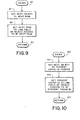
- Fig. 10 The procedure of Fig. 10 is very similar to that of Fig. 9 but concerns the cross-in list.
- next object is set to the current cross-in pointer and in block 102 the current cross-in pointer is set to the link field of the object pointed to by current cross-in.
- advance is thereby made to the next object down and determination for an object to be pixelated has been made.
- DDA is used to color pixels in the bit map.
- the object can then be drawn.
- the pixels may be executed in colors via the words that are coded into the pixel bit map memory in a well understood manner, and DDA or a digital differential analyzer may be used to maintain the average positioning of pixels around the desired line or object to be drawn.
- the current . value of DDA is retained in the object field between bands.
- neither the use of DDA to prevent line errors, or pixelation in a manner to achieve color is necessary for the operation of the present invention. For instance, pixelation can occur directly in black and white.
- an end of band indication is given by block 121 and return is made to block 25 in Fig. 2.
- a link is provided into the cross-out list.
- the link field of the object pointed to by the current-cross out is set to point to next object.
- the current cross-out is set to point to next object. The object is thereby linked to the end of the cross-out list and the pointer is advanced.
- the pixelation of this particular object is discontinued inasmuch as there is no memory space beyond the band edge.
- the object is taken from the band list and added to the end of the cross-out list.
- Current cross-out which will be pointing to the previous object in the cross-out list will be advanced so that it points to the new object reaching the band edge.
- the link field of the previous object in the list will be made to point to the new object thereby adding the new object to the cross-out list.
- the cross-out header points to the first item in the cross-out list and does not advance.
- the cross-out header and the cross-out pointer will point to the same object.
- the cross-in header is made equal to the previous cross-out header and the previous cross-out header is made NIL.
- the current cross-in pointer will point to the top of the list. The current cross-in pointer will then be used to traverse the cross-in list for pixelation (for crossing objects), in the same manner as the cross-out pointer was used to build the list.
- crossing list concept is utilized without requiring more than the storage space for five additional items, i.e. the cross-out header and pointer, the cross-in header and pointer, and the next primitive pointer.
- the lists for crossing are an integral part of the display list itself.
Abstract
Description
- The present invention relates to a method of providing pixel information for a hard copy graphics presentation, and particularly to such a method requiring a minimum bit map memory space and operating in conjunction with a hard copy device to avoid delay in providing raster information.
- In graphics display devices the information relative to objects for display may be received as a series of high level commands, each indicating the type of graphics object to be displayed and its position. Thus, such command may indicate a line is to be drawn including the origin of the line and its length in x and y coordinates. The graphics device then typically "pixelates" this information or "draws" elemental or dot portions of the line for entry into a pixel bit map memory. The pixel bit map memory is scanned or read out to provide an eventual display, using an ink jet copier or the like.
- Conventionally, all of the commands would be received for the drawing of various objects, and all of these objects would be pixelated and "laid in" to a large bit map memory before the copier starts its operation. This involves a considerable delay in loading the bit map memory before hard copy print out can begin.
- Although it is possible to portray a portion or strip of the display, thereby requiring a much smaller memory space for the bit map, nevertheless the whole bit map is ordinarily calculated or written before the presentation of each strip in order to be responsive to the graphics commands received. Thus, the bit map may be determined again and again, but only successive strips of the bit map would actually be "laid in" to the bit map memory. This involves considerable computing capability to provide the repeated bit map information.
- In accordance with the present invention in a particular embodiment thereof, the commands from a processor or the like, which describe graphics objects to be written in a display, are placed in a display list, and the display list is divided into band sublists corresponding to narrow strips or bands of a display. After the determination of the bands into which certain graphics objects are initially located, the printing or display of the information may begin. Many graphics objects would, of course, extend across a number of bands and for that reason it has been heretofore thought necessary or desirable to pixelate the entire display before execution. In the method according to the present invention, the graphics objects are pixelated within a band until it is determined that a particular object crosses from such band to a next band. For crossing objects, a separate crossing list is formed, linking objects into a further band, and this crossing list is merged with the band sublist of such further band whereby the crossing objects, and objects beginning in the further band, can be later pixelated.
- In the above manner, graphics may be input on a fairly high level basis and pixelated piecemeal for strip output allowing the use of a much smaller bit map memory than heretofore required, and allowing the initiation of a printing operation prior to the pixelation of the total display.
- It is accordingly an object of the present invention to provide an improved method of supplying raster information for a graphics display, which method is responsive to high level graphics commands, but which employs a relatively small graphics bit map memory space.
- It is a further object of the present invention to provide an improved method of supplying raster information for a graphics display wherein a hard copy printer or the like may begin operation before the total input of graphics commands for the display has been pixelated or inserted in bit map memory.
- The subject matter of the present invention is particularly pointed out and distinctly claimed in the concluding portion of this specification. However, both the organization and method of operation, together with further advantages and objects thereof, may best be understood by reference to the following description taken in connection with accompanying drawings wherein like reference characters in general refer to like elements.
-
- Fig. 1A is a schematic view of a graphics image as produced by a multiplicity of pixels,
- Fig. 1B is a block diagram of processor operated printer apparatus for using the method according to the present invention,
- Fig. 1C is an illustration of a graphics display list,
- Fig. 1D is a further view of the aforementioned display list in conjunction with an array of band sublist headers,
- Fig. 1E is an illustration of the aforementioned list as further provided with an array of band current pointers,
- Fig. 1F illustrates the aforementioned list in conjunction with crossing headers and pointers for crossing lists,
- Fig. 1G is an illustrative drawing for further explaining the operation of the display list,
- Fig. 1H is a further depiction of the aforementioned display list as responsive to the graphics illustrated in Fig. 1G,
- Fig. 11 illustrates an input graphics command, and
- Figs. 1J through 12 comprise flow charts illustrating the procedure according to the present invention.
- Referring to the drawings and particularly to Fig. lA , a graphics display is illustrated which is composed of a multiplicity of dots or "pixels" ,2, disposed in rows such as
row 3. The rows are "drawn" or imprinted by a means indicated at 4 which may correspond to the electron beam in a cathode-ray-tube, but which in the case of a hard copy printer may correspond to an ink jet or a plurality of ink jets for imprinting individual dots or pixels. The number of pixels is actually substantially greater than in the illustration, typically numbering 4,000 pixels for the long dimension of the display by 2,000 pixels for the narrower dimension, and the pixels may be imprinted in various colors or combinations of colors. - Such a display is typically computer generated, i.e. is formed in response to a plurality of high level commands which specify the graphics object or objects to be printed. For example referring to Fig. 11, one such command is shown which comprises the designation for a straight line on the display. The numbers Xl and Y1 indicate the origin of the line, while Delta X and Delta Y indicate the x and y length components of the line, as further depicted by
line 125 in Fig. 11. Other information in the command suitably comprises the type of graphics object, e.g. line, panel, character, rectangle, or the like. The link field will be hereinafter more fully described. The style field may indicate whether the line is dashed or not, the width field specifies the thickness of the line, and the color pattern field identifies the color of the line. The specific software for drawing a line or similar object on a screen or copier in response to a command is well known to those skilled in the art. - Fig. 1B illustrates a graphics system to which the present invention pertains and includes a
processor 5 coupled by an address bus and a data bus, 9a and 9b respectively, toprocessor memory 6. The processor in a specific instance was a type 68000. Further included is a bit map memory comprising a first portion 7a and asecond portion 7b that are utilized alternatively to causeink jet printer 8 to write strips or bands of the display, for example the bands as illustrated in Fig. 1G. According to the method of the present invention, band or strip pixel information is alternately written into bitmap memory portions 7a and 7b. While one section of the bit map memory is read out into the ink jet printer apparatus, the other section is receiving pixel information from the processor. - The processor operates in two passes. First, all the graphics commands are received and listed. The list is subdivided into band sublists which correspond to tne bands or strips of the display. Then in a second pass, rather than pixelate the entire picture at once (which would require an enormous memory map), pixelation occurs for just one strip or band at a time. In the specific example, a strip comprised thirty-two lines such as
pixel line 3 in Fig. lA, out of a total of about 2,000 lines. - Each band sublist of the overall display list contains the graphic objects (commands similar to that shown in Fig. 11) which begin in a particular band. For example if a line begins in
band 10 and continues to band 15, then it is contained only in theband 10 sublist. For the determination of which sublist into which a given graphics object is to be inserted, the lowest X value of the object is determined and the object is sorted into the sublist corresponding thereto. - In the second pass, the pixelation is driven by a band sublist. The graphics objects are fetched from the list one at a time, and pixelated into the bit map memory. For example, a draw line routine may be employed which would require the end point and the length of the line. The line is clipped if it extends beyond the current band, and for this purpose, the starting and ending values for the given band are also fetched.
- It is noted, during the second pass, when the information for an object indicates coordinates beyond the edge of the current band, a separate crossing sublist is established to contain the object command. This crossing list is merged with the band list for an ensuing band. Thus the line information is added to the next band at the proper location for continuing the line when the next band or strip is placed in bit map memory. Of course, during execution of the next band, only the object coordinates occurring in the next band (within its starting and ending values) are actually pixelated.
- A display list is illustrated schematically in Fig. 1C. The sequential ordering implies precedence, with objects being "drawn over" other objects which preceed them in the sequential list. The display list contains plural sublists, for example the band sublists for the separate bands to be pixelated and imprinted as hereinbefore mentioned. Each graphics object command in the list has a link field, in addition to the other graphics fields, wherein this link field enables the particular graphics object to be linked into a sublist. The end of display list pointer points to the last graphics object in the display list. At the time the graphics object in inserted into the display list (during the first pass), it is also linked into one of the band lists, and exactly one band list, namely the list corresponding to the band where the particular graphics object starts.
- In particular, the device coordinate space is divided into n bands. An array of
band headers 128 in Fig. 1D starts each of the sublists, i.e. an individual header may point to a particular graphics object which is linked with further graphics objects to form a list. For example,band sublist header 3 in Fig. 1D points to graphics object 130 which designates, in its link field, the graphics object 132. In turn, graphics object 132 is linked toobjects band sublist header 1 similarly starts a second sublist. - Referring to Fig. IE, the
display list 140 is further provided with "current"pointers 142 for the band sublists. A current pointer exists for each of the band sublists and these pointers are here shown pointing to the end of each sublist. Ordinarily, the header will start each band sublist, and the current band pointer will move along, pointing to the "next" object. - In addition to the headers and pointers hereinbefore described, crossing headers and pointers are employed for managing the crossover of a graphic from one band to another. (See Fig. 1F.) These headers and pointers pertain to crossing sublists, namely a cross-out sublist and a cross-in sublist. These crossing sublists are designated relative to the band that is being considered at a given time. Thus, a cross-out sublist indicates graphics objects that are going on to the next band, and a cross-in sublist indicates graphics objects coming from a previous band. A graphics object may be deleted from a band sublist and inserted into either of these crossing sublists, with a given graphics object residing at one time in only one sublist.
- During scan conversion or pixelation, if an object is encountered that crosses into the next band, the object is placed in the cross-out list and this cross-out list will be formed as a chain of all items that extend into the next band. Thus the commands for crossing objects will be linked together as the cross-out list. A crossing list, like the band sublists, is wholly contained in the display list and operation thereof is hereinafter more fully described in connection with the actual procedure.
- A simplified example of the listing operation will be given with respect to Figs. IG and 1H. Referring to Fig. 1G, illustrating the overall organization of the graphics display to be presented, such graphics display is divided, for purposes of illustration, into nine bands which are numbered 0 to 8 along the "X" axis, i.e. the shorter axis of the display. The display is provided to the printer, piecemeal, as each of the bands are first entered into one of the pixel bit
map memory sections 7a, 7b and then output to the printer. The X direction of the display is actually about 2,000 pixels and the Y direction of the display is actually about 4,000 pixels in a specific example, and the display is divided into bands of thirty-two scan lines each. The illustration of the display in Fig. 1G is divided into nine bands merely for ease of illustration. Four graphics objects are to be placed in the display of Fig. 1G, astraight line 144, astraight line 146, a rectangle orarea 148, and acharacter 150. - Referring now to Fig. 1H, the input commands for these objects have been listed in
display list 152.Band header array 154 contains one entry or pointer for each of the bands. The header for band 0 is NIL since no graphics object exists in band 0. The header forband 1, on the other hand, points to graphics object 144. The link field of graphics object 144 is NIL because no other graphics object starts inband 1. The band header forband 2 is NIL inasmuch as no graphics object starts inband 2. The band header forband 3 points to graphics object 146 in the display list since this graphics object starts inband 3, while the link field forobject 146 points to graphics object 148 on the display list, thereby forming a band sublist including graphics objects 146 and 148. The band header forband 6 will point to graphics object 150. Thus, a header pointer points to the start of each band sublist. - If a line, for
example line 144, doesn't terminate inband 1 during pixelation, it is linked into a crossing list which means a cross-out pointer is set to point to graphics object 144. A crossing list now contains one item, i.e. graphics object 144. Now going on toband 2,band 2 is indicated as empty so far as its band sublist is concerned, but a merge is done with the graphics object that crossed in, i.e.line 144. If other objects were contained in the band sublist forband 2, they would be merged in and pixelated into the bit map. - For
band 3, the band sublist includes two items,line 146 andrectangle 148, and the crossing list also includes one item, i.e.line 144. Therefore these three items are pixelated into the bit map forband 3. As we exitband 3, two items are added to the crossing list, namelyline 146 andrectangle 148. - As we proceed out of
band 4, it is seen thatline 144 no longer crosses. Therefore the crossing list is modified to contain only the two objects, that isline 146 andrectangle 148, while theline 144 falls away. - At any one time, one object is in one list only. As we pixelate, the object may be broken out of one list, i.e. the band sublist, and placed into another list, i.e. the crossing list, but it will only occur in one list at a time.
- There is an implicit precedence in the order that commands are received from the. processor regarding printing of one item "on top of" another. The crossing list and the band sublist will point at two different places in the display list, and so both pointers are followed, always doing whatever occurs first physically in the display list. The display list, being a sequential list, dictates the precedence. The crossing list and the band list together describe the objects that are actually active (that is the object or objects in the particular band).
- Reference will now be made to the flow charts of Figs. 1J through 12 describing operation of the present system. In addition to the previous definitions, the following variables have the following meanings in the flow charts:
- Next-object = a pointer to the object currently being pixelated.
- Next-primitive = a pointer to the next object in the current band sublist during pixelation. (This is similar to the current band list pointers as described in connection with Fig. lE.)
- Bandnum = the number of the current band.
- Referring to Fig. 1J, illustrating the first pass of the process, the program starts at 10 and initializes empty lists in block 11, i.e. for setting the lists to an empty condition (further described in connection with Fig. 3). Thereafter,
decision block 12 is entered and if the input (e.g. from a host processor) has ended, the program proceeds to the second pass of the program (Fig.2). Otherwise the next graphics object is written into a display list in block 13 (further described in Fig. 4). Inblock 14 the particular graphics object is linked into a band sublist (Fig. 5). Afterblock 14, the end of display 'list pointer in Fig. 1C is advanced to the next byte after the object just added to indicate where available memory is. This corresponds to the end of the display list. The procedure continues receiving input information and placing the information into memory. - Referring more particularly to Fig. 3, pertaining to initialization for emptying the lists for initial set up, the procedure is entered at 30, and in
block 31 the end of display list pointer (as illustrated in Fig. 1C) is set to the first byte of the display list. Inblock 32 the header (128 in Fig. 1D) is set to NIL for each band, and inblock 33 the current band pointer (142 in Fig lE) is set to the band header for each band. Return is then made to the program of Fig. 1. As further input is received, the object is written into the display list as illustrated in.Fig. 4. After entering the procedure at 40 in Fig. 4, the type field for the graphics object is written, then the link field, color field, endpoint field, and the Delta X and Delta Y fields inblocks 42 through 45. - The program of Fig. 5 is then entered at 50 to link the object into a band sublist. In
block 51 the "leftmost" coordinate of the graphics object (the lowest X coordinate thereof) is determined. (For example, see Fig 1G.) Inblock 52 the "bandnum" (band number) is set equal to the lowest value of X fromblock 51 divided by the number of scan lines per band, thirty-two in the present example. This results in the selection of the particular band in which this object starts. - In
block 53 the link field of the object pointed to by the current band pointer is set to point to the end of display list pointer. In other words, the link of the last object in this band is set to point to the new object, i.e. the pointer is set to the object that is about to be added. Inblock 54, the current band pointer is set to point to the end of display list or the location where another object will be added. The procedure of Fig. 1J is continued until all of the graphics objects have been added to the display list. - Referring to Fig. 2, the second pass, which is called scan conversion or pixelation, is entered at 20. The band sublists are reset to the front of the list in
block 21. (Reference Fig. 6.) This involves the setting of various pointers such as next primitive, cross-in and cross-out as further described in connection with Fig. 6. In the following block, 22, a value is assigned to the next object pointer as further described in Fig. 8. Indecision block 23, if the next object pointer is equal to NIL, block 28 is entered and bandnum, or the number of current band, is advanced by one. If the band number is greater that the total number of bands, the routine is completed. If it is not, the next band sublist is started as indicated in block 26 and further explained in connection with FIg. 7. Returning to block 23 if the next object pointer is other than NIL, the object is pixelated so far as it is within the band, and this is further described in connection with Fig. 12. Afterblock 24, a test is made as to whether the object crosses into the next band and if it doesn't, return is made to block 21. If it does, a link is provided into a cross-out list as further described in connection with Fig. 11. 1 - Now returning to Fig. 6, representing general resetting for the start of pixelation, the procedure is entered at 60 and in
block 61 the next primitive, which corresponds to the current pointer employed during the first pass, is set to point to the object pointed to by the first band list header, thereby requiring the next primitive pointer to point to the top of the band sublist. Inblock 62, bandnum is set equal to the first of the bands, for starting, and inblock 63 the cross-in header is set to NIL. Likewise inblock 64 the current cross-in pointer is set to point to the cross-in header. Further inblocks - Referring to Fig. 7, the next band sublist is started, assuming there was not a further object in the present band. In
block 71, the next primitive is set to point to the object pointed to by the header for the band list for the current bandnum. Inblock 72 the cross-out list is terminated by setting the link field of the object pointed to by current cross-out to NIL. Thus the end of the cross-out list is marked. In block 73 a cross-in header is set to the cross-out header for transferring from cross-out to cross-in for the next band. In block 74 the current cross-in pointer is set to point to the cross-in header for starting a list. Inblock 75 the cross-out header is set to NIL. Then the current cross-out is set to point to the cross-out header inblock 76. By the procedure of Fig. 7 the cross-out list has been transferred to the cross-in list, and a new empty cross-out list is started. Also next primitive points to the band sublist for the next band. - Referring now to Fig. 8, describing the merging of two lists, the band list and the cross-in list, and the determination of which object to pixelate next, first it is determined in
decision block 81 whether the next primitive is NIL. If it is, it is determined inblock 86 whether the current cross-in is NIL. If both are true, the next object pointer is set to NIL inblock 87. However, if the next primitive is not NIL,decision block 82 is entered and the determination is made whether the current cross-in is NIL. If the current cross-in is NIL, indicating no extensions of objects from the previous band, the program proceeds on to select from the band list inblock 84. If the current cross-in is not NIL, as determined inblock 86, the program proceeds to block 85 to select from the cross-list as further described in Fig. 10. Also, if the current cross-in is not NIL at the output ofblock 82, block 83 is entered where it is determined whether the address of the next primitive is less than the address of the current cross-in. This determination enables the "writing over" of one graphics object on another, and specifically enables the most recently received graphics object to write over a previous graphics object. If the output fromblock 83 is yes, the band list is selected in Fig. 9, and if it is not, selection is made from the cross-list of Fig. 10. Next object is set to point to the graphics object to be pixelated. - Referring to Fig. 9, block 91, the pointer, next object, i.e. the pointer to the object currently being pixelated, is set to next primitive, the pointer to the next object in the current band sublist. In the following block, 92, the next primitive is set to the link field of the object pointed to by next primitive. In other words, advance is made down the list by one, i.e. the next primitive pointer is advanced by one and next object is set to next primitive. A value has been given to next object determining what will be pixelated next.
- The procedure of Fig. 10 is very similar to that of Fig. 9 but concerns the cross-in list. In block 101, next object is set to the current cross-in pointer and in block 102 the current cross-in pointer is set to the link field of the object pointed to by current cross-in. In Fig. 10 advance is thereby made to the next object down and determination for an object to be pixelated has been made.
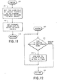
- Referring now to Fig. 12 pertaining to the pixelation of an object within the band, for X values within the current band (block 121) DDA is used to color pixels in the bit map. The object can then be drawn. The pixels may be executed in colors via the words that are coded into the pixel bit map memory in a well understood manner, and DDA or a digital differential analyzer may be used to maintain the average positioning of pixels around the desired line or object to be drawn. The current . value of DDA is retained in the object field between bands. However, neither the use of DDA to prevent line errors, or pixelation in a manner to achieve color, is necessary for the operation of the present invention. For instance, pixelation can occur directly in black and white. For X values that are not within the band, i.e. when the end of the band is reached, an end of band indication is given by
block 121 and return is made to block 25 in Fig. 2. - Now referring to Fig. 11, if a crossing was made into the next band as indicated by
block 25 in Fig. 2, a link is provided into the cross-out list. In block 111 the link field of the object pointed to by the current-cross out is set to point to next object. Inblock 112 the current cross-out is set to point to next object. The object is thereby linked to the end of the cross-out list and the pointer is advanced. - Considering further the operation of crossing an object from one band to another, when pixelation proceeds to the end of a band, the pixelation of this particular object is discontinued inasmuch as there is no memory space beyond the band edge. However, the object is taken from the band list and added to the end of the cross-out list. Current cross-out which will be pointing to the previous object in the cross-out list will be advanced so that it points to the new object reaching the band edge. The link field of the previous object in the list will be made to point to the new object thereby adding the new object to the cross-out list. It will be understood the cross-out header points to the first item in the cross-out list and does not advance. If there is only one object in the list, the cross-out header and the cross-out pointer will point to the same object. When the next band is to be pixelated, the cross-in header is made equal to the previous cross-out header and the previous cross-out header is made NIL. The current cross-in pointer will point to the top of the list. The current cross-in pointer will then be used to traverse the cross-in list for pixelation (for crossing objects), in the same manner as the cross-out pointer was used to build the list.
- It will be observed that the crossing list concept is utilized without requiring more than the storage space for five additional items, i.e. the cross-out header and pointer, the cross-in header and pointer, and the next primitive pointer. The lists for crossing, like the band lists, are an integral part of the display list itself.
- There follows a listing of the program hereinbefore illustrated in Figs. 1J through 12 and described in connection therewith.
- While a preferred embodiment of the present invention has been shown and described, it will be apparent to those skilled in the art that many changes and and modifications may be made without departing from the invention in its broader aspects. The appended claims are therefore intended to cover all such changes and modifications as fall within the true spirit and scope of the invention.
Claims (9)
Applications Claiming Priority (2)
| Application Number | Priority Date | Filing Date | Title |
|---|---|---|---|
| US06/628,182 US4660029A (en) | 1984-07-06 | 1984-07-06 | Method of providing raster information for a graphics display employing linked lists |
| US628182 | 1996-04-04 |
Publications (3)
| Publication Number | Publication Date |
|---|---|
| EP0167166A2 true EP0167166A2 (en) | 1986-01-08 |
| EP0167166A3 EP0167166A3 (en) | 1986-03-26 |
| EP0167166B1 EP0167166B1 (en) | 1990-08-22 |
Family
ID=24517820
Family Applications (1)
| Application Number | Title | Priority Date | Filing Date |
|---|---|---|---|
| EP85108294A Expired - Lifetime EP0167166B1 (en) | 1984-07-06 | 1985-07-04 | Method of providing raster information for a graphics display |
Country Status (5)
| Country | Link |
|---|---|
| US (1) | US4660029A (en) |
| EP (1) | EP0167166B1 (en) |
| JP (1) | JPS6136869A (en) |
| CA (1) | CA1235535A (en) |
| DE (1) | DE3579266D1 (en) |
Cited By (10)
| Publication number | Priority date | Publication date | Assignee | Title |
|---|---|---|---|---|
| FR2594241A1 (en) * | 1986-02-10 | 1987-08-14 | Intel Corp | DATA DISPLAY PROCESSOR ON DISPLAY SCREEN AND DATA DISPLAY METHOD USING THE DEVICE |
| DE3707112A1 (en) * | 1986-03-05 | 1987-11-26 | Minolta Camera Kk | DRAWING IMAGE CIRCUIT |
| GB2223383A (en) * | 1988-10-03 | 1990-04-04 | Sun Microsystems Inc | Graphic generation and storage |
| DE4139484A1 (en) * | 1990-11-30 | 1992-06-04 | Hitachi Ltd | Printing control system - allows data to be organised in sets that can be organised in different layout forms |
| EP0530955A1 (en) | 1991-07-09 | 1993-03-10 | Canon Kabushiki Kaisha | Image processing method and apparatus |
| EP0530954A1 (en) * | 1991-07-09 | 1993-03-10 | Canon Kabushiki Kaisha | Image processing method and apparatus |
| EP0530953A1 (en) * | 1991-07-09 | 1993-03-10 | Canon Kabushiki Kaisha | Image processing method and apparatus |
| US5261032A (en) * | 1988-10-03 | 1993-11-09 | Robert Rocchetti | Method for manipulation rectilinearly defined segmnts to form image shapes |
| EP0578256A1 (en) * | 1992-07-10 | 1994-01-12 | Microsoft Corporation | System and method of printer banding |
| EP0702328A3 (en) * | 1994-09-16 | 1996-10-30 | Canon Kk | Object based rendering system |
Families Citing this family (28)
| Publication number | Priority date | Publication date | Assignee | Title |
|---|---|---|---|---|
| SE454224B (en) * | 1985-04-10 | 1988-04-11 | Lundstrom Jan Erik | SCREEN UNIT FOR PRESENTATION OF GRAPHIC INFORMATION |
| US4980845A (en) * | 1985-08-23 | 1990-12-25 | Snap-On Tools Corporation | Digital engine analyzer |
| US5282269A (en) * | 1985-09-27 | 1994-01-25 | Oce-Nederland B.V. | Raster image memory |
| JPS62145369A (en) * | 1985-12-20 | 1987-06-29 | Hitachi Ltd | Graphic data retrieving method |
| US4852019A (en) * | 1986-01-31 | 1989-07-25 | Computer Associates International, Inc. | Method and system for retrieval of stored graphs |
| US4967375A (en) * | 1986-03-17 | 1990-10-30 | Star Technologies, Inc. | Fast architecture for graphics processor |
| US5182709A (en) * | 1986-03-31 | 1993-01-26 | Wang Laboratories, Inc. | System for parsing multidimensional and multidirectional text into encoded units and storing each encoded unit as a separate data structure |
| US4777486A (en) * | 1986-05-09 | 1988-10-11 | A-Squared Systems | Video signal receiver for computer graphics system |
| JPS63106080A (en) * | 1986-06-27 | 1988-05-11 | Hitachi Ltd | Picture display system |
| US5230066A (en) * | 1986-09-19 | 1993-07-20 | Mitsubishi Denki Kabushiki Kaisha | Microcomputer |
| US4818932A (en) * | 1986-09-25 | 1989-04-04 | Tektronix, Inc. | Concurrent memory access system |
| US4905168A (en) * | 1986-10-15 | 1990-02-27 | Atari Games Corporation | Object processing for video system using slips and linked list |
| JPS63222864A (en) * | 1987-03-12 | 1988-09-16 | Fujitsu Ltd | Page printer control |
| US4845631A (en) * | 1987-03-31 | 1989-07-04 | Rockwell International Corporation | Scrolling image memory for high speed avionics moving map display |
| US4825381A (en) * | 1987-03-31 | 1989-04-25 | Rockwell International Corporation | Moving map display |
| US4896275A (en) * | 1987-07-10 | 1990-01-23 | Bull Hn Information Systems Inc. | Full page graphics image display data reduction |
| JP2630605B2 (en) * | 1987-07-29 | 1997-07-16 | 三菱電機株式会社 | Curved surface creation method |
| US4928243A (en) * | 1987-10-06 | 1990-05-22 | Preco Industries, Inc. | Method and system for printing graphics and text from vector-based computer aided source information |
| US4929099A (en) * | 1988-01-19 | 1990-05-29 | Qume Corporation | Multi-line serial printer |
| US4954970A (en) * | 1988-04-08 | 1990-09-04 | Walker James T | Video overlay image processing apparatus |
| US5012434A (en) * | 1989-02-21 | 1991-04-30 | Siemens Aktiengesellschaft | Apparatus and method for selective rotation of data printed by a matrix printer |
| US5206629A (en) * | 1989-02-27 | 1993-04-27 | Texas Instruments Incorporated | Spatial light modulator and memory for digitized video display |
| JPH0753454B2 (en) * | 1990-07-06 | 1995-06-07 | 株式会社日立製作所 | Text information processing device |
| US5278954A (en) * | 1990-09-11 | 1994-01-11 | Analogic Corporation | System for and method of storing image data processed in multiple stages |
| US5613053A (en) | 1992-01-21 | 1997-03-18 | Compaq Computer Corporation | Video graphics controller with automatic starting for line draws |
| EP0623232B1 (en) * | 1992-01-21 | 1996-04-17 | Compaq Computer Corporation | Video graphics controller with improved calculation capabilities |
| US5500928A (en) * | 1993-03-01 | 1996-03-19 | Xionics Document Technologies, Inc. | Digital printing system and process using adaptive compression |
| JP3116732B2 (en) * | 1994-07-27 | 2000-12-11 | セイコーエプソン株式会社 | Lossless bitmap image compression method and method |
Citations (5)
| Publication number | Priority date | Publication date | Assignee | Title |
|---|---|---|---|---|
| EP0005034A2 (en) * | 1978-04-24 | 1979-10-31 | Xerox Corporation | Electronic image processing system |
| US4300206A (en) * | 1977-06-30 | 1981-11-10 | International Business Machines Corporation | Flexible text and image generator for a raster printer |
| GB2119982A (en) * | 1982-05-10 | 1983-11-23 | Xerox Corp | Printer |
| EP0048625B1 (en) * | 1980-09-22 | 1985-02-20 | Xerox Corporation | Printer interface unit with data transformation |
| EP2005034A1 (en) * | 2006-03-31 | 2008-12-24 | Robert Bosch GmbH | Gear wheel which is indented or corrugated in the direction of the circumference |
Family Cites Families (5)
| Publication number | Priority date | Publication date | Assignee | Title |
|---|---|---|---|---|
| JPS5533203A (en) * | 1978-08-30 | 1980-03-08 | Hitachi Ltd | Graphic generator of raster-scanning type display unit |
| US4203107A (en) * | 1978-11-08 | 1980-05-13 | Zentec Corporation | Microcomputer terminal system having a list mode operation for the video refresh circuit |
| US4249172A (en) * | 1979-09-04 | 1981-02-03 | Honeywell Information Systems Inc. | Row address linking control system for video display terminal |
| US4458330A (en) * | 1981-05-13 | 1984-07-03 | Intergraph Corporation | Banded vector to raster converter |
| US4496976A (en) * | 1982-12-27 | 1985-01-29 | Rockwell International Corporation | Reduced memory graphics-to-raster scan converter |
-
1984
- 1984-07-06 US US06/628,182 patent/US4660029A/en not_active Expired - Lifetime
-
1985
- 1985-06-25 CA CA000485129A patent/CA1235535A/en not_active Expired
- 1985-07-04 DE DE8585108294T patent/DE3579266D1/en not_active Expired - Fee Related
- 1985-07-04 EP EP85108294A patent/EP0167166B1/en not_active Expired - Lifetime
- 1985-07-05 JP JP14815185A patent/JPS6136869A/en active Pending
Patent Citations (5)
| Publication number | Priority date | Publication date | Assignee | Title |
|---|---|---|---|---|
| US4300206A (en) * | 1977-06-30 | 1981-11-10 | International Business Machines Corporation | Flexible text and image generator for a raster printer |
| EP0005034A2 (en) * | 1978-04-24 | 1979-10-31 | Xerox Corporation | Electronic image processing system |
| EP0048625B1 (en) * | 1980-09-22 | 1985-02-20 | Xerox Corporation | Printer interface unit with data transformation |
| GB2119982A (en) * | 1982-05-10 | 1983-11-23 | Xerox Corp | Printer |
| EP2005034A1 (en) * | 2006-03-31 | 2008-12-24 | Robert Bosch GmbH | Gear wheel which is indented or corrugated in the direction of the circumference |
Non-Patent Citations (1)
| Title |
|---|
| IBM TECHNICAL DISCLOSURE BULLETIN, vol. 24, no. 4, September 1981, pages 1938-1939, Armonk, US; G.I. FINDLEY et al.: "Character position control appartus" * |
Cited By (22)
| Publication number | Priority date | Publication date | Assignee | Title |
|---|---|---|---|---|
| FR2594241A1 (en) * | 1986-02-10 | 1987-08-14 | Intel Corp | DATA DISPLAY PROCESSOR ON DISPLAY SCREEN AND DATA DISPLAY METHOD USING THE DEVICE |
| DE3707112A1 (en) * | 1986-03-05 | 1987-11-26 | Minolta Camera Kk | DRAWING IMAGE CIRCUIT |
| DE3707112C3 (en) * | 1986-03-05 | 1995-02-09 | Minolta Camera Kk | Character image generation circuit |
| GB2223383B (en) * | 1988-10-03 | 1993-03-31 | Sun Microsystems Inc | Method and apparatus for image manipulation |
| US5261032A (en) * | 1988-10-03 | 1993-11-09 | Robert Rocchetti | Method for manipulation rectilinearly defined segmnts to form image shapes |
| AU624137B2 (en) * | 1988-10-03 | 1992-06-04 | Sun Microsystems, Inc. | Method and apparatus for image manipulation |
| GB2223383A (en) * | 1988-10-03 | 1990-04-04 | Sun Microsystems Inc | Graphic generation and storage |
| DE4139484A1 (en) * | 1990-11-30 | 1992-06-04 | Hitachi Ltd | Printing control system - allows data to be organised in sets that can be organised in different layout forms |
| US5615316A (en) * | 1990-11-30 | 1997-03-25 | Hitachi, Ltd. | Printing control method and apparatus |
| US5379368A (en) * | 1990-11-30 | 1995-01-03 | Hitachi, Ltd. | Printing control method and apparatus |
| EP0530955A1 (en) | 1991-07-09 | 1993-03-10 | Canon Kabushiki Kaisha | Image processing method and apparatus |
| EP0530954A1 (en) * | 1991-07-09 | 1993-03-10 | Canon Kabushiki Kaisha | Image processing method and apparatus |
| EP0530953A1 (en) * | 1991-07-09 | 1993-03-10 | Canon Kabushiki Kaisha | Image processing method and apparatus |
| US5517317A (en) * | 1991-07-09 | 1996-05-14 | Canon Kabushiki Kaisha | Image processing method and apparatus which selectively develop coded recording information into bit image data |
| US5825994A (en) * | 1991-07-09 | 1998-10-20 | Canon Kabushiki Kaisha | Image processing method and apparatus |
| US5757948A (en) * | 1991-07-09 | 1998-05-26 | Canon Kabushiki Kaisha | Method and device for processing coded record information to obtain bit image data |
| EP0578256A1 (en) * | 1992-07-10 | 1994-01-12 | Microsoft Corporation | System and method of printer banding |
| US5604847A (en) * | 1992-07-10 | 1997-02-18 | Microsoft Corporation | System and method of printer banding |
| US5588095A (en) * | 1992-07-10 | 1996-12-24 | Microsoft Corporation | System and method of printer banding |
| US5577173A (en) * | 1992-07-10 | 1996-11-19 | Microsoft Corporation | System and method of printer banding |
| EP0702328A3 (en) * | 1994-09-16 | 1996-10-30 | Canon Kk | Object based rendering system |
| US5912672A (en) * | 1994-09-16 | 1999-06-15 | Canon Kabushiki Kaisha | Object based rendering system for the rendering of images using edge based object descriptions and setable level indicators |
Also Published As
| Publication number | Publication date |
|---|---|
| JPS6136869A (en) | 1986-02-21 |
| DE3579266D1 (en) | 1990-09-27 |
| EP0167166A3 (en) | 1986-03-26 |
| EP0167166B1 (en) | 1990-08-22 |
| US4660029A (en) | 1987-04-21 |
| CA1235535A (en) | 1988-04-19 |
Similar Documents
| Publication | Publication Date | Title |
|---|---|---|
| US4660029A (en) | Method of providing raster information for a graphics display employing linked lists | |
| US7999971B2 (en) | Optimization techniques during processing of print jobs | |
| EP0115584B1 (en) | Image producing apparatus and methods of processing image-representing signals for use by such apparatus | |
| JP2790285B2 (en) | Full page graphics image display data compression method and apparatus | |
| EP0438038B1 (en) | Graphics processor | |
| US5404233A (en) | Method for smoothing image | |
| US6582046B1 (en) | Method and device for image processing | |
| US4887228A (en) | Method for filling surface parts of an image with a surface pattern | |
| US5553205A (en) | System and method of transferring a bit-mapped image using raster columns | |
| US4555763A (en) | Method and apparatus for storage and accessing of characters, and electronic printer employing same | |
| EP0940975A2 (en) | Printing of hybrid images, including halftoning | |
| EP0229539B1 (en) | Color plotter controller | |
| US5889931A (en) | Image output method and apparatus thereof | |
| JP3285930B2 (en) | Image processing device | |
| US5159666A (en) | Apparatus and a method for enlarging dot matrix data | |
| JP3085175B2 (en) | Drawing equipment | |
| US6504543B1 (en) | Polygon drawing method and polygon drawing apparatus | |
| EP1398688A2 (en) | Information processing apparatus, image formation apparatus, drawing processing method | |
| EP0009662B1 (en) | Method and apparatus for storing and reconstructing chinese-like characters | |
| EP0146714A2 (en) | Method and system for creating visual displays of data from an input data set | |
| US5016190A (en) | Development of raster scan images from independent cells of imaged data | |
| AU7876887A (en) | Printer character generator | |
| JP2000013601A (en) | Print information processor and device and method for generating intermediate data | |
| JPH0239818B2 (en) | ||
| JP3089906B2 (en) | Drawing equipment |
Legal Events
| Date | Code | Title | Description |
|---|---|---|---|
| PUAI | Public reference made under article 153(3) epc to a published international application that has entered the european phase |
Free format text: ORIGINAL CODE: 0009012 |
|
| AK | Designated contracting states |
Designated state(s): DE FR GB NL |
|
| PUAL | Search report despatched |
Free format text: ORIGINAL CODE: 0009013 |
|
| AK | Designated contracting states |
Kind code of ref document: A3 Designated state(s): DE FR GB NL |
|
| 17P | Request for examination filed |
Effective date: 19860424 |
|
| 17Q | First examination report despatched |
Effective date: 19880715 |
|
| GRAA | (expected) grant |
Free format text: ORIGINAL CODE: 0009210 |
|
| AK | Designated contracting states |
Kind code of ref document: B1 Designated state(s): DE FR GB NL |
|
| ET | Fr: translation filed | ||
| REF | Corresponds to: |
Ref document number: 3579266 Country of ref document: DE Date of ref document: 19900927 |
|
| PLBE | No opposition filed within time limit |
Free format text: ORIGINAL CODE: 0009261 |
|
| STAA | Information on the status of an ep patent application or granted ep patent |
Free format text: STATUS: NO OPPOSITION FILED WITHIN TIME LIMIT |
|
| 26N | No opposition filed | ||
| PGFP | Annual fee paid to national office [announced via postgrant information from national office to epo] |
Ref country code: GB Payment date: 19920617 Year of fee payment: 8 Ref country code: DE Payment date: 19920617 Year of fee payment: 8 |
|
| PGFP | Annual fee paid to national office [announced via postgrant information from national office to epo] |
Ref country code: FR Payment date: 19920728 Year of fee payment: 8 |
|
| PGFP | Annual fee paid to national office [announced via postgrant information from national office to epo] |
Ref country code: NL Payment date: 19920731 Year of fee payment: 8 |
|
| PG25 | Lapsed in a contracting state [announced via postgrant information from national office to epo] |
Ref country code: GB Effective date: 19930704 |
|
| PG25 | Lapsed in a contracting state [announced via postgrant information from national office to epo] |
Ref country code: NL Effective date: 19940201 |
|
| GBPC | Gb: european patent ceased through non-payment of renewal fee |
Effective date: 19930704 |
|
| NLV4 | Nl: lapsed or anulled due to non-payment of the annual fee | ||
| PG25 | Lapsed in a contracting state [announced via postgrant information from national office to epo] |
Ref country code: FR Effective date: 19940331 |
|
| PG25 | Lapsed in a contracting state [announced via postgrant information from national office to epo] |
Ref country code: DE Effective date: 19940401 |
|
| REG | Reference to a national code |
Ref country code: FR Ref legal event code: ST |