EP0164561A2 - Flow control valve - Google Patents
Flow control valve Download PDFInfo
- Publication number
- EP0164561A2 EP0164561A2 EP85105467A EP85105467A EP0164561A2 EP 0164561 A2 EP0164561 A2 EP 0164561A2 EP 85105467 A EP85105467 A EP 85105467A EP 85105467 A EP85105467 A EP 85105467A EP 0164561 A2 EP0164561 A2 EP 0164561A2
- Authority
- EP
- European Patent Office
- Prior art keywords
- pressure
- port
- valve
- valve seat
- poppet
- Prior art date
- Legal status (The legal status is an assumption and is not a legal conclusion. Google has not performed a legal analysis and makes no representation as to the accuracy of the status listed.)
- Granted
Links
Images

Classifications
-
- F—MECHANICAL ENGINEERING; LIGHTING; HEATING; WEAPONS; BLASTING
- F16—ENGINEERING ELEMENTS AND UNITS; GENERAL MEASURES FOR PRODUCING AND MAINTAINING EFFECTIVE FUNCTIONING OF MACHINES OR INSTALLATIONS; THERMAL INSULATION IN GENERAL
- F16K—VALVES; TAPS; COCKS; ACTUATING-FLOATS; DEVICES FOR VENTING OR AERATING
- F16K31/00—Actuating devices; Operating means; Releasing devices
- F16K31/12—Actuating devices; Operating means; Releasing devices actuated by fluid
- F16K31/42—Actuating devices; Operating means; Releasing devices actuated by fluid by means of electrically-actuated members in the supply or discharge conduits of the fluid motor
-
- F—MECHANICAL ENGINEERING; LIGHTING; HEATING; WEAPONS; BLASTING
- F15—FLUID-PRESSURE ACTUATORS; HYDRAULICS OR PNEUMATICS IN GENERAL
- F15B—SYSTEMS ACTING BY MEANS OF FLUIDS IN GENERAL; FLUID-PRESSURE ACTUATORS, e.g. SERVOMOTORS; DETAILS OF FLUID-PRESSURE SYSTEMS, NOT OTHERWISE PROVIDED FOR
- F15B21/00—Common features of fluid actuator systems; Fluid-pressure actuator systems or details thereof, not covered by any other group of this subclass
- F15B21/08—Servomotor systems incorporating electrically operated control means
-
- Y—GENERAL TAGGING OF NEW TECHNOLOGICAL DEVELOPMENTS; GENERAL TAGGING OF CROSS-SECTIONAL TECHNOLOGIES SPANNING OVER SEVERAL SECTIONS OF THE IPC; TECHNICAL SUBJECTS COVERED BY FORMER USPC CROSS-REFERENCE ART COLLECTIONS [XRACs] AND DIGESTS
- Y10—TECHNICAL SUBJECTS COVERED BY FORMER USPC
- Y10T—TECHNICAL SUBJECTS COVERED BY FORMER US CLASSIFICATION
- Y10T137/00—Fluid handling
- Y10T137/8593—Systems
- Y10T137/86389—Programmer or timer
- Y10T137/86405—Repeating cycle
- Y10T137/86421—Variable
-
- Y—GENERAL TAGGING OF NEW TECHNOLOGICAL DEVELOPMENTS; GENERAL TAGGING OF CROSS-SECTIONAL TECHNOLOGIES SPANNING OVER SEVERAL SECTIONS OF THE IPC; TECHNICAL SUBJECTS COVERED BY FORMER USPC CROSS-REFERENCE ART COLLECTIONS [XRACs] AND DIGESTS
- Y10—TECHNICAL SUBJECTS COVERED BY FORMER USPC
- Y10T—TECHNICAL SUBJECTS COVERED BY FORMER US CLASSIFICATION
- Y10T137/00—Fluid handling
- Y10T137/8593—Systems
- Y10T137/86389—Programmer or timer
- Y10T137/86445—Plural, sequential, valve actuations
- Y10T137/86461—Variable cycle
-
- Y—GENERAL TAGGING OF NEW TECHNOLOGICAL DEVELOPMENTS; GENERAL TAGGING OF CROSS-SECTIONAL TECHNOLOGIES SPANNING OVER SEVERAL SECTIONS OF THE IPC; TECHNICAL SUBJECTS COVERED BY FORMER USPC CROSS-REFERENCE ART COLLECTIONS [XRACs] AND DIGESTS
- Y10—TECHNICAL SUBJECTS COVERED BY FORMER USPC
- Y10T—TECHNICAL SUBJECTS COVERED BY FORMER US CLASSIFICATION
- Y10T137/00—Fluid handling
- Y10T137/8593—Systems
- Y10T137/87265—Dividing into parallel flow paths with recombining
- Y10T137/87298—Having digital flow controller
-
- Y—GENERAL TAGGING OF NEW TECHNOLOGICAL DEVELOPMENTS; GENERAL TAGGING OF CROSS-SECTIONAL TECHNOLOGIES SPANNING OVER SEVERAL SECTIONS OF THE IPC; TECHNICAL SUBJECTS COVERED BY FORMER USPC CROSS-REFERENCE ART COLLECTIONS [XRACs] AND DIGESTS
- Y10—TECHNICAL SUBJECTS COVERED BY FORMER USPC
- Y10T—TECHNICAL SUBJECTS COVERED BY FORMER US CLASSIFICATION
- Y10T137/00—Fluid handling
- Y10T137/8593—Systems
- Y10T137/87265—Dividing into parallel flow paths with recombining
- Y10T137/8741—With common operator
-
- Y—GENERAL TAGGING OF NEW TECHNOLOGICAL DEVELOPMENTS; GENERAL TAGGING OF CROSS-SECTIONAL TECHNOLOGIES SPANNING OVER SEVERAL SECTIONS OF THE IPC; TECHNICAL SUBJECTS COVERED BY FORMER USPC CROSS-REFERENCE ART COLLECTIONS [XRACs] AND DIGESTS
- Y10—TECHNICAL SUBJECTS COVERED BY FORMER USPC
- Y10T—TECHNICAL SUBJECTS COVERED BY FORMER US CLASSIFICATION
- Y10T137/00—Fluid handling
- Y10T137/8593—Systems
- Y10T137/87265—Dividing into parallel flow paths with recombining
- Y10T137/87507—Electrical actuator
Definitions
- the present invention relates to a flow control valve, and more particularly, to a quite new flow control valve 3esigned to control a flux of the fluid in response to the number of input pulses.
- Flow control valves designed to control a flux of the fluid in response to an electric signal have heretofore been known, however, such conventional types of flow control valves were generally so constructed that initially a sawtooth-wave-form pulse signal and a variable reference level pulse signal are both sent to a comparator circuit and then the valve is opened when the level of said sawtooth-wave-form pulse signal is larger than that of reference level pulse signal. That is, these types of flow control valves are generally to control the flux of fluid by a so-called pulse width modulation system.
- the present invention is proposed in view of the status quo like this and aims at providing an entirely new flow control valve designed to exactly control the flux of fluid in response to the pulse frequency.
- the flow control valve under the present invention is so designed that a valve seat opened and closed by a poppet is each provided at "IN”- and "OUT"- port sides of a fluid passage routing from the "IN"-port to the "OUT"-port and, said each poppet to open and close said each valve seat is actuated by differential pressure of the pressurized fluid applied to pressure chambers arranged opposite to each other and, said correspondent poppet is actuated to apply the pressure to said pressure chamber of said "IN”-port side to open said correspondent valve seat according to a timing synchronized with the pulse signal of variable frequency sent from a pulse oscillator and, said correspondent poppet is also actuated to apply the pressure to said pressure chamber of said "OUT"-port side to close said correspondent valve seat in accordance with a timing just at that time when the predetermined time lapsed away and, the flux flowing from "IN"-port to "OUT”-port can thereby be controlled exactly by controlling a frequency of the pulse signal.
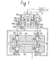
- FIG.1 a structural diagram showing an ideal embodiment of the present invention is illustrated therein.
- a pair of fluid passages 4a & 4b are arranged in parallel to each other between "IN"-port 2 and "OUT"-port 3 of the valve body 1.
- valve seat 9a located on the way from “IN”- port 2 to the fluid passage 4a is opened or closed by a poppet 5a and, a valve seat 9b located on the way from “IN”-port 2 to the passage 4b is opened or closed by a poppet 5b.
- a valve seat 12a located on the way from the passage 4a to "OUT"-port 3 is opened or closed by a poppet 6a and, a valve seat 12b located on the way from the passage 4b to "OUT"-port 3 is opened or closed by a poppet 6b likewise.
- the pilot pressure is applied to the pressure chambers 8a & llb and the valve seats 9a & 12b are both closed and further the pilot pressure is applied to the pressure chamber 8b in response to the fact that a pulse signal reflected on another polarity at a state where the valve seats 9b & 12a are opened and .then the pilot pressure is applied to the pressure chamber 11a after keeping a predetermined time lag, the operating oil will flow from "IN"-port 2 to "OUT"-port 3 through the passage 4a for a period of time until the valve seat 12a is closed after the valve seat 9a has been opened.
- the present embodiment is so contrived that a changeover between the supply of pilot pressure to the pressure chambers 8a & 11b and the supply of pilot pressure to the pressure chambers 8b & lla is carried out correspondingly by a polar inversion of the pulse emitted from a pulse oscillator 13 generating a variable frequency and also a time lag until the pilot pressure is supplied to the pressure chamber lib after the pilot pressure has been supplied to the pressure chamber 8a is set by a diametral control of the orifice 14 and in addition a time lag until the pilot pressure is supplied to the pressure chamber lla after the pilot pressure has been supplied to the pressure chamber 8b is set by a diametral control of the orifice 15 and thereby the flux flowing from "IN"-port 2 to "OUT"-port 3 can be controlled by the frequency of pulse signal emitted from the pulse oscillator 13.
- the present invention will then be described as for a mechanism and its composition for carrying out a changeover of the pilot pressure and a setting of the time lag.
- a drive pin 17 is illustrated therein, which is, e.g., made of a ferromagnetic body with a low residual magnetism like a soft iron and supported at its central portion to be freely oscillatable to a pin 16 of the valve body 1.
- a pair of coils 18a & 18b are wound up to said drive pin 17. Each one end of these coils 18a & 18b is OR-connected and led to the ground and another each one end of said coils is also OR-connected and led to an output of the pulse oscillator 13.
- the coils 18a & 18b are so wound up to the drive pin 17 that, when the output of the pulse oscillator 13 is in the state of plus, the left end of said drive pin 17 is "N"-pole and the right end of the same is “S"-pole and also, when the output of the pulse oscillator 13 is minus, the left end of the drive pin 17 is "S"-pole and the right end of the same is “N"-pole.
- numeric numbers 19a & 19b in Fig.1 denote each a pilot valve fixed to the valve body 1.
- up-down pins 20a & 20b are inserted to be freely ascendable and descendable and the top ends of said up-down pins 20a & 20b reach respectively the left and right end portions of said drive pin 17.
- the pilot valve 19a is-to conduct or shut off the passage between pressure lines 21a and 22a.
- the up-down pin 20a is actuated to push down a sphere 23 against the pilot pressure, the passage between pressure lines 21a and 22a will be shut off.
- the pilot pressure sent through the pilot valve 19a is supplied to the pressure chamber 8a through the pressure line 22a and then sent to the pressure chamber llb after a time lag determined by the diametral control of the orifice 14 has lapsed away.
- the pilot valve 19b is to conduct or shut off the passage between pressure lines 21b and 22b.
- the up-down pin 20b is actuated to push down the sphere 23b against the pilot pressure, the passage between pressure lines 21b and 22b will be shut off.
- the pilot pressure sent through the pilot valve 19b is supplied to the pressure chamber 8b through the pressure line 22b and then sent to the pressure chamber 11a after the time lag determined by the diametral control of the orifice 15.
- the numeric number 24 shows a pilot pressure source, and four permanent magnets 25a, 25b, 25c and 25d are arranged facing their different poles respectively inwards on and under both ends of the drive pin 17.
- the present invention will then be described as for an action of the embodiment by reference to a timing chart of Fig.2.
- the type (a) shows a pattern of the pulse signal generated by the pulse oscillator 13
- the type (b) shows a pattern of the time "T” which the operating oil passes through the fluid passage 4b
- the type (c) shows a pattern of the time "T” which the operating oil passes through the fluid passage 4a respectively.
- the up-down pin 20a acts to push down the sphere 23a against the pilot pressure, so that the passage between pressure lines 21a and 22a will be shut off. Also, as the sphere 23b is pushed down by the pilot pressure and the passage between pressure lines 21b and 22b is conducted, the pilot pressure will come to be supplied to the pressure chambers 8b and 11a of the valve body.l. Therefore, in the initial stage, as shown in Fig.l, the poppet 5a acts to open the valve seat 9a but the poppet 6a acts to close the valve seat 12a, so that the operating oil cannot flow from "IN"-port 2 to "OUT"-port 3 through the fluid passage 4a. Also, the poppet 6b acts to open the valve seat 12b but the poppet 5b acts to close the valve seat 9b, so that the operating oil cannot flow from "IN"-port 2 to "OUT”-port 3 through the fluid passage 4b.
- the pilot pressure is sent to the pressure chamber 8a and then sent to the same llb after the time lag "T" set by the diametral control of the orifice 14 has lapsed away.
- valve seat 9a When the pilot pressure is applied to the pressure chamber 8a, the valve seat 9a will be closed and at the same time the pressure chamber 8b will be opened.
- the valve seat 12b As the valve seat 12b is opened until the time lag "T" set by the diametral control of the orifice 14 lapses away, the operating oil will come to flow from "IN"-port 2 to "OUT"-port 3 through the fluid passage 4b within the range of time "T” shown in Fig.2 (b). And, the valve seat 12b is closed by the pilot pressure applied to the pressure chamber 11b after the time "T" set by the diametral control of the orifice 14 has lapsed away, so that the operating oil flowing through the fluid passage 4b ceases its flow completely.
- the poppets 5a and 6b act to close the valve seats 9a and 12b and at the same time the poppets 5b and 6a continue to act to open the valve seats 9b and 12a respectively.
- the up-down pin 20a works to push down the sphere 23a against the pilot pressure, so that the passage between pressure lines 21a and 22a is shut off and in consequence the pilot pressure cannot be applied to both of the pressure chambers 8a and 11b. And, at the same time as the sphere 23a is pushed down by the action of the up-down pin 20a, the sphere 23b is pushed up by the pilot pressure and the passage between pressure lines 21b and 22b comes to conduction.
- valve seat 9b When the pilot pressure is applied to the pressure chamber 8b, the valve seat 9b will be shut off, and at the same time the valve seat 9a will be opened. And, as the valve seat 12a continues to be opened until the time "T" set by the diametral control of the orifice 15 lapses away, the operating oil flows from "IN"-port 2 to "OUT"-port 3 through the fluid passage 4a within the range of the time "T” shown in Fig.2 (c).
- the present embodiment is so contrived that, when a polarity of the pulse generated by the pulse oscillator 13 is inversed from minus to plus, the operating oil flows through the fluid passage 4b until a very short time "T" set by the diametral control of the orifice 14 lapses away as shown in Fig.2 (b) and also when a polarity of the pulse generated by the pulse oscillator 13 is inversed from plus to minus, the operating oil flows through the fluid passage 4a until a very short time "T" set by the diametral control of the orifice 15 lapses away. Namely, the operating oil flows only for a period of the time "T" whenever a polarity of the pulse is inversed.
- a flux per pulse of the operating oil flowing from "IN"-port 2 to "OUT”-port 3 is determined in proportion to a length of the very short time "T" for which the fluid passage 4a or 4b is opened, and said very short time “T” is set by the diametral control of the orifices 14 and 15. Accordingly, if the aforesaid time lag "T" is preset by controlling a diameter of the orifices 14 and 15, the flux per one pulse of the operating oil flowing from "IN"-port 2 to "OUT”-port 3 can be determined uniformly.
- a flux per unit time (e.g., 1 second) of the operating oil flowing from "IN"-port 2 to "OUT"-port 3 is given by a value which is obtained by multiplying the flux per pulse of the operating oil by the number of pulses per unit time (e.g.,1 second)
- the flux per unit time (e.g., 1 second) can be controlled exactly.
- time lag "T" from the moment when the pilot pressure is applied to the pressure chamber 8a or 8b to the moment when the pilot pressure is applied to the pressure chamber 11b or 11a is set by the diametral control of the orifices 14 and 15 is shown therein, however, any method is available, provided that the time lag "T" from the moment when the pilot pressure is applied to the pressure chamber 8a or 8b to the moment when it is applied to the pressure chamber 11b or lla can be set exactly. For instance, it is also allowable to electrically set the time lag in an electric circuit by controlling a charge time of condenser or the like.
- pilot pressure obtained from a single pilot pressure source through the changeover between pilot valves 19a and 19b is supplied to either of the pressure chambers 8a & 11b or the same 8b & 11a is shown therein, however, it is also justifiable that an independent pilot pressure source is provided for each of pilot valves 19a & 19b or for each of pressure chambers 8a & 8b and the same lla & 11b and the time lag "T" is contrived to be set by a delay circuit in which "CR" or the like is built.
- an ideal control characteristic can be obtained by adjusting not only a frequency of the pulse oscillator but also an output voltage of the same or by carrying out a diametral adjustment of the orifice.
- an accurate flow control can be attained by controlling the pulse frequency. And, as a leakage of the operating oil can completely be prevented through the engagement of poppet and valve seat, the flux per pulse can exactly be controlled.
- the present invention makes it needless to use a highly mechanized control technique like a flux feedback and so on ; besides makes it possible to simplify its control mechanism to the full extent.
- the present flow control valve can display its function most satisfactorily as a drive means for an equipment having a large reaction force.
Abstract
Description
- The present invention relates to a flow control valve, and more particularly, to a quite new flow control valve 3esigned to control a flux of the fluid in response to the number of input pulses.
- Flow control valves designed to control a flux of the fluid in response to an electric signal have heretofore been known, however, such conventional types of flow control valves were generally so constructed that initially a sawtooth-wave-form pulse signal and a variable reference level pulse signal are both sent to a comparator circuit and then the valve is opened when the level of said sawtooth-wave-form pulse signal is larger than that of reference level pulse signal. That is, these types of flow control valves are generally to control the flux of fluid by a so-called pulse width modulation system.
- Consequently, in such conventional flow control valves, an electric circuit was especially sophisticated, while their responsive performances and controllable accuracies were not always satisfiable for users from the reason of structural limitation of the valve body to be used.
- The present invention is proposed in view of the status quo like this and aims at providing an entirely new flow control valve designed to exactly control the flux of fluid in response to the pulse frequency.
- To sum up, the flow control valve under the present invention is so designed that a valve seat opened and closed by a poppet is each provided at "IN"- and "OUT"- port sides of a fluid passage routing from the "IN"-port to the "OUT"-port and, said each poppet to open and close said each valve seat is actuated by differential pressure of the pressurized fluid applied to pressure chambers arranged opposite to each other and, said correspondent poppet is actuated to apply the pressure to said pressure chamber of said "IN"-port side to open said correspondent valve seat according to a timing synchronized with the pulse signal of variable frequency sent from a pulse oscillator and, said correspondent poppet is also actuated to apply the pressure to said pressure chamber of said "OUT"-port side to close said correspondent valve seat in accordance with a timing just at that time when the predetermined time lapsed away and, the flux flowing from "IN"-port to "OUT"-port can thereby be controlled exactly by controlling a frequency of the pulse signal.
-
- Fig.l is a structural diagram of the mechanism showing an embodiment of the present invention, and
- Fig.2 is an operational timing chart of the embodiment shown in Fig.l.
- In these drawings, each numeric number denotes ;

- The present invention will now be described in more details by reference to the accompanying drawings as for its embodiment.
- Initially, referring to Fig.1, a structural diagram showing an ideal embodiment of the present invention is illustrated therein. A pair of
fluid passages 4a & 4b are arranged in parallel to each other between "IN"-port 2 and "OUT"-port 3 of thevalve body 1. - And, a valve seat 9a located on the way from "IN"- port 2 to the
fluid passage 4a is opened or closed by apoppet 5a and, a valve seat 9b located on the way from "IN"-port 2 to thepassage 4b is opened or closed by apoppet 5b. Also, avalve seat 12a located on the way from thepassage 4a to "OUT"-port 3 is opened or closed by apoppet 6a and, avalve seat 12b located on the way from thepassage 4b to "OUT"-port 3 is opened or closed by apoppet 6b likewise. - Thereupon, linking the
poppet 5a with the same 5b by a pin 7 and also floating them insidepressure chambers 8a & 8b arranged opposite to each other by a differential pressure between said facingchambers poppet 5b when thepoppet 5a acts to close the valve seat 9a and also to close the valve seat 9b by thepoppet 5b when thepoppet 5a acts to open the valve seat 9a. Accordingly, such events that both of the valve seats 9a and 9b are simultaneously closed or opened can be avoided. - In the same way, linking the
poppet 6a with the same 6b by the pin 10 and floating them inside the pressure chambers lla & 1Tb arranged opposite to each other by the differential pressure between said facingchambers 11a & llb will make it possible to open thevalve seat 12b by thepoppet 6b when thepoppet 6a acts to close thevalve seat 12a and also to close thevalve seat 12b by thepoppet 6b when thepoppet 6a acts to open thevalve seat 12a. Consequently, such events that both of thevalve seats 12a & 12b are simultaneously closed or opend can be avoided. - Accordingly, if a pilot pressure is applied to the
pressure chambers 8b & lla and the valve seats 9b & 12a are both closed and further the pilot pressure is applied to thepressure chamber 8a in response to the fact that a pulse signal reflected on a certain polarity at a state where the valve seats 9a & 12b are opend and then the pilot pressure is applied to the pressure chamber llb after keeping a predetermined time lag, an operating oil will flow from "IN"-port 2 to "OUT"-port 3 through thepassage 4b for a period of time until thevalve seat 12b is closed after the valve seat 9b has been opened. - In the same way, if the pilot pressure is applied to the
pressure chambers 8a & llb and the valve seats 9a & 12b are both closed and further the pilot pressure is applied to thepressure chamber 8b in response to the fact that a pulse signal reflected on another polarity at a state where the valve seats 9b & 12a are opened and .then the pilot pressure is applied to thepressure chamber 11a after keeping a predetermined time lag, the operating oil will flow from "IN"-port 2 to "OUT"-port 3 through thepassage 4a for a period of time until thevalve seat 12a is closed after the valve seat 9a has been opened. - Accordingly, the present embodiment is so contrived that a changeover between the supply of pilot pressure to the
pressure chambers 8a & 11b and the supply of pilot pressure to thepressure chambers 8b & lla is carried out correspondingly by a polar inversion of the pulse emitted from apulse oscillator 13 generating a variable frequency and also a time lag until the pilot pressure is supplied to the pressure chamber lib after the pilot pressure has been supplied to thepressure chamber 8a is set by a diametral control of theorifice 14 and in addition a time lag until the pilot pressure is supplied to the pressure chamber lla after the pilot pressure has been supplied to thepressure chamber 8b is set by a diametral control of theorifice 15 and thereby the flux flowing from "IN"-port 2 to "OUT"-port 3 can be controlled by the frequency of pulse signal emitted from thepulse oscillator 13. - Therefore, the present invention will then be described as for a mechanism and its composition for carrying out a changeover of the pilot pressure and a setting of the time lag.
- Initially, referring to Fig.l, a
drive pin 17 is illustrated therein, which is, e.g., made of a ferromagnetic body with a low residual magnetism like a soft iron and supported at its central portion to be freely oscillatable to apin 16 of thevalve body 1. A pair ofcoils 18a & 18b are wound up to said drivepin 17. Each one end of thesecoils 18a & 18b is OR-connected and led to the ground and another each one end of said coils is also OR-connected and led to an output of thepulse oscillator 13. - Incidentally, the
coils 18a & 18b are so wound up to thedrive pin 17 that, when the output of thepulse oscillator 13 is in the state of plus, the left end of saiddrive pin 17 is "N"-pole and the right end of the same is "S"-pole and also, when the output of thepulse oscillator 13 is minus, the left end of thedrive pin 17 is "S"-pole and the right end of the same is "N"-pole. - In this connection, the
numeric numbers 19a & 19b in Fig.1 denote each a pilot valve fixed to thevalve body 1. Into thesepilot valves 19a & 19b, up-down pins 20a & 20b are inserted to be freely ascendable and descendable and the top ends of said up-down pins 20a & 20b reach respectively the left and right end portions of saiddrive pin 17. - Incidentally, the
pilot valve 19a is-to conduct or shut off the passage betweenpressure lines sphere 23 against the pilot pressure, the passage betweenpressure lines sphere 23a is pushed up by the pilot pressure, the passage betweenpressure lines pilot valve 19a is supplied to thepressure chamber 8a through thepressure line 22a and then sent to the pressure chamber llb after a time lag determined by the diametral control of theorifice 14 has lapsed away. - Also, the
pilot valve 19b is to conduct or shut off the passage betweenpressure lines pin 20b is actuated to push down thesphere 23b against the pilot pressure, the passage betweenpressure lines sphere 23b is pushed up by the pilot pressure, the passage betweenpressure lines pilot valve 19b is supplied to thepressure chamber 8b through thepressure line 22b and then sent to thepressure chamber 11a after the time lag determined by the diametral control of theorifice 15. - In passing, the
numeric number 24 shows a pilot pressure source, and fourpermanent magnets drive pin 17. - Well, the present invention will then be described as for an action of the embodiment by reference to a timing chart of Fig.2. In fig.2, the type (a) shows a pattern of the pulse signal generated by the
pulse oscillator 13, the type (b) shows a pattern of the time "T" which the operating oil passes through thefluid passage 4b and the type (c) shows a pattern of the time "T" which the operating oil passes through thefluid passage 4a respectively. - Now, let it be supposed that a polarity of the pulse generated by the
pulse oscillator 13 is minus at its initial stage, as shown in Fig.2 (a). - As has been noted previously, when the output polarity of the
pulse oscillator 13 is minus, the left end of thedrive pin 17 is "S"-pole and the right end of the same is "N"-pole. Consequently, thedrive pin 17 will naturally turn counterclockwise centering thepin 16 and, its left end will come to be attracted to thepermanent magnet 25b and its right end to themagnet 25c. - Accordingly, in the initial stage, as shown in Fig.1, the up-down pin 20a acts to push down the
sphere 23a against the pilot pressure, so that the passage betweenpressure lines sphere 23b is pushed down by the pilot pressure and the passage betweenpressure lines pressure chambers poppet 5a acts to open the valve seat 9a but thepoppet 6a acts to close thevalve seat 12a, so that the operating oil cannot flow from "IN"-port 2 to "OUT"-port 3 through thefluid passage 4a. Also, thepoppet 6b acts to open thevalve seat 12b but thepoppet 5b acts to close the valve seat 9b, so that the operating oil cannot flow from "IN"-port 2 to "OUT"-port 3 through thefluid passage 4b. - Therefore, in this state, the fluid passage between "IN"-port 2 and "OUT"-port 3 comes to be shut off.
- In this state, when a polarity of the pulse generated by the
pulse oscillator 13 is inversed and turns to plus, a polarity of thedrive pin 17 is also inversed and its left end turns to "N"-pole and its right end to "S"-pole, and then said left end is attracted to thepermanent magnet 25a and said right end to the same 25d respectively. - Consequently, as the up-down
pin 20b acts to push down thesphere 23b against the pilot pressure, the passage betweenpressure lines pressure chambers 8b and lla. And, at the same time as thesphere 23b is pushed down by the action of the up-downpin 20b, thesphere 23a is pushed up by the pilot pressure and the passage betweenpressure lines - Thus, when the passage between
pressure lines pressure chamber 8a and then sent to the same llb after the time lag "T" set by the diametral control of theorifice 14 has lapsed away. - Now, when the pilot pressure is applied to the
pressure chamber 8a, the valve seat 9a will be closed and at the same time thepressure chamber 8b will be opened. As thevalve seat 12b is opened until the time lag "T" set by the diametral control of theorifice 14 lapses away, the operating oil will come to flow from "IN"-port 2 to "OUT"-port 3 through thefluid passage 4b within the range of time "T" shown in Fig.2 (b). And, thevalve seat 12b is closed by the pilot pressure applied to thepressure chamber 11b after the time "T" set by the diametral control of theorifice 14 has lapsed away, so that the operating oil flowing through thefluid passage 4b ceases its flow completely. After this, until a polarity of the pulse generated by thepulse oscillator 13 is inversed, thepoppets valve seats 9a and 12b and at the same time thepoppets valve seats 9b and 12a respectively. - Next, in the state where the pilot pressure is thus applied to the
pressure chambers pulse oscillator 13 is re- inversed and turns to minus, the left end of thedrive pin 17 will come to "S"-pole and the right end of the same to "N"-pole and then the left end of thedrive pin 17 is attracted to thepermanent magnet 25b and its right end to the same 25c respectively. - Accordingly, the up-down pin 20a works to push down the
sphere 23a against the pilot pressure, so that the passage betweenpressure lines pressure chambers sphere 23a is pushed down by the action of the up-down pin 20a, thesphere 23b is pushed up by the pilot pressure and the passage betweenpressure lines - And, when the passage between
pressure lines pressure chamber 8b and then sent to the same 11a after the time lag "T" set by the diametral control of theorifice 15 has lapsed away. - When the pilot pressure is applied to the
pressure chamber 8b, the valve seat 9b will be shut off, and at the same time the valve seat 9a will be opened. And, as thevalve seat 12a continues to be opened until the time "T" set by the diametral control of theorifice 15 lapses away, the operating oil flows from "IN"-port 2 to "OUT"-port 3 through thefluid passage 4a within the range of the time "T" shown in Fig.2 (c). - And, when the time "T" set by the diametral control of the
orifice 15 lapses away, the pilot pressure will be applied to the pressure chamber lla and thevalve seat 12a will thereby be closed and in consequence the flow of the operating oil through thefluid passage 4a ceases completely. And, until a polarity of the pulse generated by thepulse oscillator 13 is then inversed, thepoppets valve seats 9b and 12a respectively and also thepoppets valve seats 9a and 12b. - In this way, the present embodiment is so contrived that, when a polarity of the pulse generated by the
pulse oscillator 13 is inversed from minus to plus, the operating oil flows through thefluid passage 4b until a very short time "T" set by the diametral control of theorifice 14 lapses away as shown in Fig.2 (b) and also when a polarity of the pulse generated by thepulse oscillator 13 is inversed from plus to minus, the operating oil flows through thefluid passage 4a until a very short time "T" set by the diametral control of theorifice 15 lapses away. Namely, the operating oil flows only for a period of the time "T" whenever a polarity of the pulse is inversed. - And, a flux per pulse of the operating oil flowing from "IN"-port 2 to "OUT"-port 3 is determined in proportion to a length of the very short time "T" for which the
fluid passage orifices orifices - And, as a flux per unit time (e.g., 1 second) of the operating oil flowing from "IN"-port 2 to "OUT"-port 3 is given by a value which is obtained by multiplying the flux per pulse of the operating oil by the number of pulses per unit time (e.g.,1 second), if a frequency of the pulse generated by the
pulse oscillator 13 is controlled by a time constants of saidoscillator 13, the flux per unit time (e.g., 1 second) can be controlled exactly. - In the aforementioned embodiment, such an example that the
fluid passages 4a & 4b are arranged in parallel to each other and the operating oil is displaced in both cases where a polarity of the pulse is inversed from plus to minus and vice versa is shown, however, the flux control can be accomplished by controlling the pulse frequency even if either of thefluid passages - Also, in the aforementioned embodiment, an example that the up-down
pins 20a and 20b are raised or lowered through the oscillation centering thepin 16 and a changeover of the pilot pressure is performed is shown therein, however, there is no objection even in lifting up or down thepins 20a and 20b with the use of, e.g., individually independent solenoid. - Moreover, in the abovenoted embodiment, an example that the time lag "T" from the moment when the pilot pressure is applied to the
pressure chamber pressure chamber orifices pressure chamber pressure chamber 11b or lla can be set exactly. For instance, it is also allowable to electrically set the time lag in an electric circuit by controlling a charge time of condenser or the like. - Furthermore, in the foregoing embodiment, an example that the pilot pressure obtained from a single pilot pressure source through the changeover between
pilot valves pressure chambers 8a & 11b or the same 8b & 11a is shown therein, however, it is also justifiable that an independent pilot pressure source is provided for each ofpilot valves 19a & 19b or for each ofpressure chambers 8a & 8b and the same lla & 11b and the time lag "T" is contrived to be set by a delay circuit in which "CR" or the like is built. - Yet further, it will easily be understood from the foregoing embodiment that an ideal control characteristic can be obtained by adjusting not only a frequency of the pulse oscillator but also an output voltage of the same or by carrying out a diametral adjustment of the orifice.
- As has been understood from the above, according to the present invention, an accurate flow control can be attained by controlling the pulse frequency. And, as a leakage of the operating oil can completely be prevented through the engagement of poppet and valve seat, the flux per pulse can exactly be controlled. Thus, the present invention makes it needless to use a highly mechanized control technique like a flux feedback and so on ; besides makes it possible to simplify its control mechanism to the full extent.
- Moreover, as it is possible to arrest a so-called reaction force exactly through the engagement of poppet and valve seat, the present flow control valve can display its function most satisfactorily as a drive means for an equipment having a large reaction force.
Claims (1)
- A flow control valve characterized by such a contrivance that :a valve seat opened and closed by a poppet is each provided at "IN"- and "OUT"-port sides on a fluid passage routing from the "IN"-port to the "OUT" port,each poppet to open and close said each valve seat is actuated by a differential pressure applied to pressure chambers arranged opposite to each other, andsaid correspondent poppets act to apply a pressure to the pressure chamber of said "IN"-port side to open said correspondent valve seats in accordance with a timing synchronized with a pulse signal of variable frequency and, said correspondent poppets also act to apply the pressure to the pressure chamber of said "OUT"-port side to close said correspondent valve seats in accordance with a timing at that time when the predetermined time lapsed away.
Applications Claiming Priority (2)
| Application Number | Priority Date | Filing Date | Title |
|---|---|---|---|
| JP59122588A JPS612985A (en) | 1984-06-14 | 1984-06-14 | Flow control valve |
| JP122588/84 | 1984-06-14 |
Publications (3)
| Publication Number | Publication Date |
|---|---|
| EP0164561A2 true EP0164561A2 (en) | 1985-12-18 |
| EP0164561A3 EP0164561A3 (en) | 1987-12-02 |
| EP0164561B1 EP0164561B1 (en) | 1990-08-08 |
Family
ID=14839634
Family Applications (1)
| Application Number | Title | Priority Date | Filing Date |
|---|---|---|---|
| EP85105467A Expired - Lifetime EP0164561B1 (en) | 1984-06-14 | 1985-05-04 | Flow control valve |
Country Status (6)
| Country | Link |
|---|---|
| US (1) | US4609011A (en) |
| EP (1) | EP0164561B1 (en) |
| JP (1) | JPS612985A (en) |
| KR (1) | KR920002316B1 (en) |
| DE (1) | DE3579049D1 (en) |
| SU (1) | SU1412602A3 (en) |
Cited By (1)
| Publication number | Priority date | Publication date | Assignee | Title |
|---|---|---|---|---|
| CN107091369A (en) * | 2017-05-10 | 2017-08-25 | 宁波兴茂电子科技有限公司 | A kind of pilot valve discharge characteristic test device and its application method |
Families Citing this family (7)
| Publication number | Priority date | Publication date | Assignee | Title |
|---|---|---|---|---|
| JPS63303276A (en) * | 1987-05-30 | 1988-12-09 | Aida Eng Ltd | Valve mechanism |
| US4951459A (en) * | 1988-08-30 | 1990-08-28 | Allied-Signal Inc. | Methods for metering fluid and apparatus for use therewith |
| US6534003B1 (en) * | 1999-04-02 | 2003-03-18 | Ethicon, Inc. | Valve and a method of using a valve |
| US6058956A (en) * | 1997-08-25 | 2000-05-09 | Baker, Jr.; G. Paul | Cycling self checking block valve |
| US6763832B1 (en) * | 1999-04-27 | 2004-07-20 | Loma Linda University Medical Center | Device and method for the administration of oxygen |
| KR101478066B1 (en) * | 2013-04-15 | 2015-01-06 | 주식회사 만도 | Apparatus of controlling solenoid valve and control method of thereof |
| US20160084405A1 (en) * | 2014-09-24 | 2016-03-24 | George Paul Baker, Jr. | Online full stroke testing overpressurization safety relief valve |
Citations (6)
| Publication number | Priority date | Publication date | Assignee | Title |
|---|---|---|---|---|
| US2800885A (en) * | 1954-12-30 | 1957-07-30 | Ibm | Hydraulic control apparatus |
| GB869105A (en) * | 1958-12-08 | 1961-05-31 | Rech Etudes Prod | Improved hydraulic actuators |
| FR1470343A (en) * | 1965-12-28 | 1967-02-24 | Generator of periodic fluid signals, applicable in particular to the control of a breathing mask | |
| GB1083944A (en) * | 1964-10-22 | 1967-09-20 | Zd Y Prumyslove Automatisace | A pneumatic trigger circuit with a single input |
| US4161264A (en) * | 1977-06-17 | 1979-07-17 | Johnson Bryan E | Fluid metering and mixing device having inlet and outlet valves |
| US4281584A (en) * | 1978-06-01 | 1981-08-04 | Deutsche Forschungs- Und Versuchsanstalt Fur Luft- U. Raumfahrt | Electro-hydraulic regulating drive and a fast-switching magnetic valve for use therein |
Family Cites Families (2)
| Publication number | Priority date | Publication date | Assignee | Title |
|---|---|---|---|---|
| AT242459B (en) * | 1962-11-24 | 1965-09-27 | Teves Kg Alfred | Current regulator |
| CH520876A (en) * | 1971-07-30 | 1972-03-31 | Luwa Ag | Pneumatic control |
-
1984
- 1984-06-14 JP JP59122588A patent/JPS612985A/en active Granted
-
1985
- 1985-05-02 US US06/729,629 patent/US4609011A/en not_active Expired - Fee Related
- 1985-05-04 DE DE8585105467T patent/DE3579049D1/en not_active Expired - Fee Related
- 1985-05-04 EP EP85105467A patent/EP0164561B1/en not_active Expired - Lifetime
- 1985-05-17 KR KR1019850003381A patent/KR920002316B1/en not_active IP Right Cessation
- 1985-06-13 SU SU853910505A patent/SU1412602A3/en active
Patent Citations (6)
| Publication number | Priority date | Publication date | Assignee | Title |
|---|---|---|---|---|
| US2800885A (en) * | 1954-12-30 | 1957-07-30 | Ibm | Hydraulic control apparatus |
| GB869105A (en) * | 1958-12-08 | 1961-05-31 | Rech Etudes Prod | Improved hydraulic actuators |
| GB1083944A (en) * | 1964-10-22 | 1967-09-20 | Zd Y Prumyslove Automatisace | A pneumatic trigger circuit with a single input |
| FR1470343A (en) * | 1965-12-28 | 1967-02-24 | Generator of periodic fluid signals, applicable in particular to the control of a breathing mask | |
| US4161264A (en) * | 1977-06-17 | 1979-07-17 | Johnson Bryan E | Fluid metering and mixing device having inlet and outlet valves |
| US4281584A (en) * | 1978-06-01 | 1981-08-04 | Deutsche Forschungs- Und Versuchsanstalt Fur Luft- U. Raumfahrt | Electro-hydraulic regulating drive and a fast-switching magnetic valve for use therein |
Cited By (2)
| Publication number | Priority date | Publication date | Assignee | Title |
|---|---|---|---|---|
| CN107091369A (en) * | 2017-05-10 | 2017-08-25 | 宁波兴茂电子科技有限公司 | A kind of pilot valve discharge characteristic test device and its application method |
| CN107091369B (en) * | 2017-05-10 | 2023-06-30 | 宁波兴茂电子科技有限公司 | Pilot valve flow characteristic testing device and application method thereof |
Also Published As
| Publication number | Publication date |
|---|---|
| US4609011A (en) | 1986-09-02 |
| EP0164561B1 (en) | 1990-08-08 |
| JPS612985A (en) | 1986-01-08 |
| SU1412602A3 (en) | 1988-07-23 |
| KR860000492A (en) | 1986-01-29 |
| DE3579049D1 (en) | 1990-09-13 |
| KR920002316B1 (en) | 1992-03-21 |
| EP0164561A3 (en) | 1987-12-02 |
| JPH0326306B2 (en) | 1991-04-10 |
Similar Documents
| Publication | Publication Date | Title |
|---|---|---|
| RU2074990C1 (en) | Distributing valve unit | |
| US3443585A (en) | Magnetically operated multi-valve assembly | |
| EP0164561A2 (en) | Flow control valve | |
| GB2400161A (en) | Hydraulic valve with force feedback spring | |
| JPS6415584A (en) | Control valve | |
| EP0366960A3 (en) | Operation-monitored valve | |
| JPS6474371A (en) | Electromagnetically operable valve gear | |
| GB578799A (en) | Improvements in devices for recocking and firing automatic guns | |
| JPH0456911B2 (en) | ||
| EP0038128A1 (en) | Electro-hydraulic servo activator system | |
| US5419369A (en) | Solenoid operated pressure control valve | |
| US5503174A (en) | Process for actuating a slide valve designed as a magnetic valve, magnetic valve for carrying out said process | |
| JPH0477840B2 (en) | ||
| JPS57127177A (en) | Flow controlling device | |
| JPS62220783A (en) | Solenoid-operated flow regulating valve | |
| JPS6221830Y2 (en) | ||
| SU1201804A1 (en) | Device for controlling pressure in chamber | |
| JPS6447693A (en) | Damper for two-wheel barrow | |
| US10073470B1 (en) | High speed, broad range electro pneumatic flow control valve | |
| JPS60231082A (en) | Flow control device of flow control valve | |
| JPS60196474A (en) | Poppet type flow control valve | |
| JPS5683675A (en) | 2-port, 2-position switching valve | |
| JPS5950284A (en) | Multi-stage electromagnetic control valve | |
| JPS63318301A (en) | Fluid controller | |
| JPS5673202A (en) | Remote-controlled valve system |
Legal Events
| Date | Code | Title | Description |
|---|---|---|---|
| PUAI | Public reference made under article 153(3) epc to a published international application that has entered the european phase |
Free format text: ORIGINAL CODE: 0009012 |
|
| AK | Designated contracting states |
Designated state(s): CH DE FR GB IT LI SE |
|
| PUAL | Search report despatched |
Free format text: ORIGINAL CODE: 0009013 |
|
| AK | Designated contracting states |
Kind code of ref document: A3 Designated state(s): CH DE FR GB IT LI SE |
|
| 17P | Request for examination filed |
Effective date: 19880504 |
|
| 17Q | First examination report despatched |
Effective date: 19890420 |
|
| RAP3 | Party data changed (applicant data changed or rights of an application transferred) |
Owner name: AIDA ENGINEERING, LTD. |
|
| ITF | It: translation for a ep patent filed |
Owner name: ING. ZINI MARANESI & C. S.R.L. |
|
| GRAA | (expected) grant |
Free format text: ORIGINAL CODE: 0009210 |
|
| AK | Designated contracting states |
Kind code of ref document: B1 Designated state(s): CH DE FR GB IT LI SE |
|
| PG25 | Lapsed in a contracting state [announced via postgrant information from national office to epo] |
Ref country code: SE Free format text: THE PATENT HAS BEEN ANNULLED BY A DECISION OF A NATIONAL AUTHORITY Effective date: 19900808 Ref country code: LI Effective date: 19900808 Ref country code: CH Effective date: 19900808 |
|
| REF | Corresponds to: |
Ref document number: 3579049 Country of ref document: DE Date of ref document: 19900913 |
|
| ET | Fr: translation filed | ||
| REG | Reference to a national code |
Ref country code: CH Ref legal event code: PL |
|
| ITTA | It: last paid annual fee | ||
| PLBE | No opposition filed within time limit |
Free format text: ORIGINAL CODE: 0009261 |
|
| STAA | Information on the status of an ep patent application or granted ep patent |
Free format text: STATUS: NO OPPOSITION FILED WITHIN TIME LIMIT |
|
| 26N | No opposition filed | ||
| PGFP | Annual fee paid to national office [announced via postgrant information from national office to epo] |
Ref country code: DE Payment date: 19920529 Year of fee payment: 10 |
|
| PGFP | Annual fee paid to national office [announced via postgrant information from national office to epo] |
Ref country code: GB Payment date: 19930423 Year of fee payment: 9 |
|
| PGFP | Annual fee paid to national office [announced via postgrant information from national office to epo] |
Ref country code: FR Payment date: 19930511 Year of fee payment: 9 |
|
| PG25 | Lapsed in a contracting state [announced via postgrant information from national office to epo] |
Ref country code: GB Effective date: 19940504 |
|
| GBPC | Gb: european patent ceased through non-payment of renewal fee |
Effective date: 19940504 |
|
| PG25 | Lapsed in a contracting state [announced via postgrant information from national office to epo] |
Ref country code: FR Effective date: 19950131 |
|
| REG | Reference to a national code |
Ref country code: FR Ref legal event code: ST |
|
| PG25 | Lapsed in a contracting state [announced via postgrant information from national office to epo] |
Ref country code: DE Effective date: 19960201 |