EP0162368A2 - Injection gas-generating device, particularly for charging mineral oil from its underground reservoirs - Google Patents
Injection gas-generating device, particularly for charging mineral oil from its underground reservoirs Download PDFInfo
- Publication number
- EP0162368A2 EP0162368A2 EP85105564A EP85105564A EP0162368A2 EP 0162368 A2 EP0162368 A2 EP 0162368A2 EP 85105564 A EP85105564 A EP 85105564A EP 85105564 A EP85105564 A EP 85105564A EP 0162368 A2 EP0162368 A2 EP 0162368A2
- Authority
- EP
- European Patent Office
- Prior art keywords
- gas
- thermal energy
- energy generation
- air separation
- compressor
- Prior art date
- Legal status (The legal status is an assumption and is not a legal conclusion. Google has not performed a legal analysis and makes no representation as to the accuracy of the status listed.)
- Withdrawn
Links
Images


Classifications
-
- B—PERFORMING OPERATIONS; TRANSPORTING
- B01—PHYSICAL OR CHEMICAL PROCESSES OR APPARATUS IN GENERAL
- B01J—CHEMICAL OR PHYSICAL PROCESSES, e.g. CATALYSIS OR COLLOID CHEMISTRY; THEIR RELEVANT APPARATUS
- B01J19/00—Chemical, physical or physico-chemical processes in general; Their relevant apparatus
- B01J19/14—Production of inert gas mixtures; Use of inert gases in general
-
- E—FIXED CONSTRUCTIONS
- E21—EARTH DRILLING; MINING
- E21B—EARTH DRILLING, e.g. DEEP DRILLING; OBTAINING OIL, GAS, WATER, SOLUBLE OR MELTABLE MATERIALS OR A SLURRY OF MINERALS FROM WELLS
- E21B43/00—Methods or apparatus for obtaining oil, gas, water, soluble or meltable materials or a slurry of minerals from wells
- E21B43/16—Enhanced recovery methods for obtaining hydrocarbons
- E21B43/166—Injecting a gaseous medium; Injecting a gaseous medium and a liquid medium
- E21B43/168—Injecting a gaseous medium
-
- F—MECHANICAL ENGINEERING; LIGHTING; HEATING; WEAPONS; BLASTING
- F01—MACHINES OR ENGINES IN GENERAL; ENGINE PLANTS IN GENERAL; STEAM ENGINES
- F01K—STEAM ENGINE PLANTS; STEAM ACCUMULATORS; ENGINE PLANTS NOT OTHERWISE PROVIDED FOR; ENGINES USING SPECIAL WORKING FLUIDS OR CYCLES
- F01K23/00—Plants characterised by more than one engine delivering power external to the plant, the engines being driven by different fluids
- F01K23/02—Plants characterised by more than one engine delivering power external to the plant, the engines being driven by different fluids the engine cycles being thermally coupled
- F01K23/06—Plants characterised by more than one engine delivering power external to the plant, the engines being driven by different fluids the engine cycles being thermally coupled combustion heat from one cycle heating the fluid in another cycle
- F01K23/064—Plants characterised by more than one engine delivering power external to the plant, the engines being driven by different fluids the engine cycles being thermally coupled combustion heat from one cycle heating the fluid in another cycle in combination with an industrial process, e.g. chemical, metallurgical
-
- F—MECHANICAL ENGINEERING; LIGHTING; HEATING; WEAPONS; BLASTING
- F25—REFRIGERATION OR COOLING; COMBINED HEATING AND REFRIGERATION SYSTEMS; HEAT PUMP SYSTEMS; MANUFACTURE OR STORAGE OF ICE; LIQUEFACTION SOLIDIFICATION OF GASES
- F25J—LIQUEFACTION, SOLIDIFICATION OR SEPARATION OF GASES OR GASEOUS OR LIQUEFIED GASEOUS MIXTURES BY PRESSURE AND COLD TREATMENT OR BY BRINGING THEM INTO THE SUPERCRITICAL STATE
- F25J3/00—Processes or apparatus for separating the constituents of gaseous or liquefied gaseous mixtures involving the use of liquefaction or solidification
- F25J3/02—Processes or apparatus for separating the constituents of gaseous or liquefied gaseous mixtures involving the use of liquefaction or solidification by rectification, i.e. by continuous interchange of heat and material between a vapour stream and a liquid stream
- F25J3/04—Processes or apparatus for separating the constituents of gaseous or liquefied gaseous mixtures involving the use of liquefaction or solidification by rectification, i.e. by continuous interchange of heat and material between a vapour stream and a liquid stream for air
- F25J3/04006—Providing pressurised feed air or process streams within or from the air fractionation unit
- F25J3/04012—Providing pressurised feed air or process streams within or from the air fractionation unit by compression of warm gaseous streams; details of intake or interstage cooling
- F25J3/04018—Providing pressurised feed air or process streams within or from the air fractionation unit by compression of warm gaseous streams; details of intake or interstage cooling of main feed air
-
- F—MECHANICAL ENGINEERING; LIGHTING; HEATING; WEAPONS; BLASTING
- F25—REFRIGERATION OR COOLING; COMBINED HEATING AND REFRIGERATION SYSTEMS; HEAT PUMP SYSTEMS; MANUFACTURE OR STORAGE OF ICE; LIQUEFACTION SOLIDIFICATION OF GASES
- F25J—LIQUEFACTION, SOLIDIFICATION OR SEPARATION OF GASES OR GASEOUS OR LIQUEFIED GASEOUS MIXTURES BY PRESSURE AND COLD TREATMENT OR BY BRINGING THEM INTO THE SUPERCRITICAL STATE
- F25J3/00—Processes or apparatus for separating the constituents of gaseous or liquefied gaseous mixtures involving the use of liquefaction or solidification
- F25J3/02—Processes or apparatus for separating the constituents of gaseous or liquefied gaseous mixtures involving the use of liquefaction or solidification by rectification, i.e. by continuous interchange of heat and material between a vapour stream and a liquid stream
- F25J3/04—Processes or apparatus for separating the constituents of gaseous or liquefied gaseous mixtures involving the use of liquefaction or solidification by rectification, i.e. by continuous interchange of heat and material between a vapour stream and a liquid stream for air
- F25J3/04006—Providing pressurised feed air or process streams within or from the air fractionation unit
- F25J3/04012—Providing pressurised feed air or process streams within or from the air fractionation unit by compression of warm gaseous streams; details of intake or interstage cooling
- F25J3/0403—Providing pressurised feed air or process streams within or from the air fractionation unit by compression of warm gaseous streams; details of intake or interstage cooling of nitrogen
-
- F—MECHANICAL ENGINEERING; LIGHTING; HEATING; WEAPONS; BLASTING
- F25—REFRIGERATION OR COOLING; COMBINED HEATING AND REFRIGERATION SYSTEMS; HEAT PUMP SYSTEMS; MANUFACTURE OR STORAGE OF ICE; LIQUEFACTION SOLIDIFICATION OF GASES
- F25J—LIQUEFACTION, SOLIDIFICATION OR SEPARATION OF GASES OR GASEOUS OR LIQUEFIED GASEOUS MIXTURES BY PRESSURE AND COLD TREATMENT OR BY BRINGING THEM INTO THE SUPERCRITICAL STATE
- F25J3/00—Processes or apparatus for separating the constituents of gaseous or liquefied gaseous mixtures involving the use of liquefaction or solidification
- F25J3/02—Processes or apparatus for separating the constituents of gaseous or liquefied gaseous mixtures involving the use of liquefaction or solidification by rectification, i.e. by continuous interchange of heat and material between a vapour stream and a liquid stream
- F25J3/04—Processes or apparatus for separating the constituents of gaseous or liquefied gaseous mixtures involving the use of liquefaction or solidification by rectification, i.e. by continuous interchange of heat and material between a vapour stream and a liquid stream for air
- F25J3/04006—Providing pressurised feed air or process streams within or from the air fractionation unit
- F25J3/04109—Arrangements of compressors and /or their drivers
- F25J3/04115—Arrangements of compressors and /or their drivers characterised by the type of prime driver, e.g. hot gas expander
- F25J3/04121—Steam turbine as the prime mechanical driver
-
- F—MECHANICAL ENGINEERING; LIGHTING; HEATING; WEAPONS; BLASTING
- F25—REFRIGERATION OR COOLING; COMBINED HEATING AND REFRIGERATION SYSTEMS; HEAT PUMP SYSTEMS; MANUFACTURE OR STORAGE OF ICE; LIQUEFACTION SOLIDIFICATION OF GASES
- F25J—LIQUEFACTION, SOLIDIFICATION OR SEPARATION OF GASES OR GASEOUS OR LIQUEFIED GASEOUS MIXTURES BY PRESSURE AND COLD TREATMENT OR BY BRINGING THEM INTO THE SUPERCRITICAL STATE
- F25J3/00—Processes or apparatus for separating the constituents of gaseous or liquefied gaseous mixtures involving the use of liquefaction or solidification
- F25J3/02—Processes or apparatus for separating the constituents of gaseous or liquefied gaseous mixtures involving the use of liquefaction or solidification by rectification, i.e. by continuous interchange of heat and material between a vapour stream and a liquid stream
- F25J3/04—Processes or apparatus for separating the constituents of gaseous or liquefied gaseous mixtures involving the use of liquefaction or solidification by rectification, i.e. by continuous interchange of heat and material between a vapour stream and a liquid stream for air
- F25J3/04006—Providing pressurised feed air or process streams within or from the air fractionation unit
- F25J3/04109—Arrangements of compressors and /or their drivers
- F25J3/04115—Arrangements of compressors and /or their drivers characterised by the type of prime driver, e.g. hot gas expander
- F25J3/04127—Gas turbine as the prime mechanical driver
-
- F—MECHANICAL ENGINEERING; LIGHTING; HEATING; WEAPONS; BLASTING
- F25—REFRIGERATION OR COOLING; COMBINED HEATING AND REFRIGERATION SYSTEMS; HEAT PUMP SYSTEMS; MANUFACTURE OR STORAGE OF ICE; LIQUEFACTION SOLIDIFICATION OF GASES
- F25J—LIQUEFACTION, SOLIDIFICATION OR SEPARATION OF GASES OR GASEOUS OR LIQUEFIED GASEOUS MIXTURES BY PRESSURE AND COLD TREATMENT OR BY BRINGING THEM INTO THE SUPERCRITICAL STATE
- F25J3/00—Processes or apparatus for separating the constituents of gaseous or liquefied gaseous mixtures involving the use of liquefaction or solidification
- F25J3/02—Processes or apparatus for separating the constituents of gaseous or liquefied gaseous mixtures involving the use of liquefaction or solidification by rectification, i.e. by continuous interchange of heat and material between a vapour stream and a liquid stream
- F25J3/04—Processes or apparatus for separating the constituents of gaseous or liquefied gaseous mixtures involving the use of liquefaction or solidification by rectification, i.e. by continuous interchange of heat and material between a vapour stream and a liquid stream for air
- F25J3/04006—Providing pressurised feed air or process streams within or from the air fractionation unit
- F25J3/04109—Arrangements of compressors and /or their drivers
- F25J3/04139—Combination of different types of drivers mechanically coupled to the same compressor, possibly split on multiple compressor casings
-
- F—MECHANICAL ENGINEERING; LIGHTING; HEATING; WEAPONS; BLASTING
- F25—REFRIGERATION OR COOLING; COMBINED HEATING AND REFRIGERATION SYSTEMS; HEAT PUMP SYSTEMS; MANUFACTURE OR STORAGE OF ICE; LIQUEFACTION SOLIDIFICATION OF GASES
- F25J—LIQUEFACTION, SOLIDIFICATION OR SEPARATION OF GASES OR GASEOUS OR LIQUEFIED GASEOUS MIXTURES BY PRESSURE AND COLD TREATMENT OR BY BRINGING THEM INTO THE SUPERCRITICAL STATE
- F25J3/00—Processes or apparatus for separating the constituents of gaseous or liquefied gaseous mixtures involving the use of liquefaction or solidification
- F25J3/02—Processes or apparatus for separating the constituents of gaseous or liquefied gaseous mixtures involving the use of liquefaction or solidification by rectification, i.e. by continuous interchange of heat and material between a vapour stream and a liquid stream
- F25J3/04—Processes or apparatus for separating the constituents of gaseous or liquefied gaseous mixtures involving the use of liquefaction or solidification by rectification, i.e. by continuous interchange of heat and material between a vapour stream and a liquid stream for air
- F25J3/04521—Coupling of the air fractionation unit to an air gas-consuming unit, so-called integrated processes
- F25J3/04563—Integration with a nitrogen consuming unit, e.g. for purging, inerting, cooling or heating
- F25J3/04569—Integration with a nitrogen consuming unit, e.g. for purging, inerting, cooling or heating for enhanced or tertiary oil recovery
-
- F—MECHANICAL ENGINEERING; LIGHTING; HEATING; WEAPONS; BLASTING
- F25—REFRIGERATION OR COOLING; COMBINED HEATING AND REFRIGERATION SYSTEMS; HEAT PUMP SYSTEMS; MANUFACTURE OR STORAGE OF ICE; LIQUEFACTION SOLIDIFICATION OF GASES
- F25J—LIQUEFACTION, SOLIDIFICATION OR SEPARATION OF GASES OR GASEOUS OR LIQUEFIED GASEOUS MIXTURES BY PRESSURE AND COLD TREATMENT OR BY BRINGING THEM INTO THE SUPERCRITICAL STATE
- F25J3/00—Processes or apparatus for separating the constituents of gaseous or liquefied gaseous mixtures involving the use of liquefaction or solidification
- F25J3/02—Processes or apparatus for separating the constituents of gaseous or liquefied gaseous mixtures involving the use of liquefaction or solidification by rectification, i.e. by continuous interchange of heat and material between a vapour stream and a liquid stream
- F25J3/04—Processes or apparatus for separating the constituents of gaseous or liquefied gaseous mixtures involving the use of liquefaction or solidification by rectification, i.e. by continuous interchange of heat and material between a vapour stream and a liquid stream for air
- F25J3/04521—Coupling of the air fractionation unit to an air gas-consuming unit, so-called integrated processes
- F25J3/04563—Integration with a nitrogen consuming unit, e.g. for purging, inerting, cooling or heating
- F25J3/04575—Integration with a nitrogen consuming unit, e.g. for purging, inerting, cooling or heating for a gas expansion plant, e.g. dilution of the combustion gas in a gas turbine
-
- F—MECHANICAL ENGINEERING; LIGHTING; HEATING; WEAPONS; BLASTING
- F25—REFRIGERATION OR COOLING; COMBINED HEATING AND REFRIGERATION SYSTEMS; HEAT PUMP SYSTEMS; MANUFACTURE OR STORAGE OF ICE; LIQUEFACTION SOLIDIFICATION OF GASES
- F25J—LIQUEFACTION, SOLIDIFICATION OR SEPARATION OF GASES OR GASEOUS OR LIQUEFIED GASEOUS MIXTURES BY PRESSURE AND COLD TREATMENT OR BY BRINGING THEM INTO THE SUPERCRITICAL STATE
- F25J3/00—Processes or apparatus for separating the constituents of gaseous or liquefied gaseous mixtures involving the use of liquefaction or solidification
- F25J3/02—Processes or apparatus for separating the constituents of gaseous or liquefied gaseous mixtures involving the use of liquefaction or solidification by rectification, i.e. by continuous interchange of heat and material between a vapour stream and a liquid stream
- F25J3/04—Processes or apparatus for separating the constituents of gaseous or liquefied gaseous mixtures involving the use of liquefaction or solidification by rectification, i.e. by continuous interchange of heat and material between a vapour stream and a liquid stream for air
- F25J3/04521—Coupling of the air fractionation unit to an air gas-consuming unit, so-called integrated processes
- F25J3/04593—The air gas consuming unit is also fed by an air stream
-
- F—MECHANICAL ENGINEERING; LIGHTING; HEATING; WEAPONS; BLASTING
- F25—REFRIGERATION OR COOLING; COMBINED HEATING AND REFRIGERATION SYSTEMS; HEAT PUMP SYSTEMS; MANUFACTURE OR STORAGE OF ICE; LIQUEFACTION SOLIDIFICATION OF GASES
- F25J—LIQUEFACTION, SOLIDIFICATION OR SEPARATION OF GASES OR GASEOUS OR LIQUEFIED GASEOUS MIXTURES BY PRESSURE AND COLD TREATMENT OR BY BRINGING THEM INTO THE SUPERCRITICAL STATE
- F25J2215/00—Processes characterised by the type or other details of the product stream
- F25J2215/02—Mixing or blending of fluids to yield a certain product
-
- F—MECHANICAL ENGINEERING; LIGHTING; HEATING; WEAPONS; BLASTING
- F25—REFRIGERATION OR COOLING; COMBINED HEATING AND REFRIGERATION SYSTEMS; HEAT PUMP SYSTEMS; MANUFACTURE OR STORAGE OF ICE; LIQUEFACTION SOLIDIFICATION OF GASES
- F25J—LIQUEFACTION, SOLIDIFICATION OR SEPARATION OF GASES OR GASEOUS OR LIQUEFIED GASEOUS MIXTURES BY PRESSURE AND COLD TREATMENT OR BY BRINGING THEM INTO THE SUPERCRITICAL STATE
- F25J2245/00—Processes or apparatus involving steps for recycling of process streams
- F25J2245/42—Processes or apparatus involving steps for recycling of process streams the recycled stream being nitrogen
Definitions
- the invention relates to a device according to the preamble of claim 1.
- Nitrogen e.g. Nitrogen or a mixture of nitrogen and carbon dioxide obtained by burning hydrocarbons.
- the gas must be able to be produced inexpensively in large quantities.
- nitrogen for the stated purpose, which is obtained by separating air into oxygen and nitrogen using an air separation plant.
- the energy requirement for generating a nominal volume unit of nitrogen is lower than for generating a standard volume unit of combustion gas according to the previously described method.
- an air separation plant requires higher investments than a combustion gas plant of the same capacity.
- Nitrogen or a mixture of nitrogen and carbon dioxide obtained from combustion gas has long been used in technology for other purposes, especially for inerting plants which process combustible substances or at all for displacing or diluting atmospheric oxygen.
- Known devices for generating these gases have mainly been developed as inert gas generators.
- the use of combustion inert gas is preferred due to the lower investment costs, if the special application does not require pure nitrogen.
- air separation is more advantageous because of the lower energy consumption per quantity of inert gas generated.
- the invention has for its object to provide a device of the type specified in the preamble of claim 1, which makes it possible to produce large amounts of injection gas inexpensively and with little energy.
- This object is achieved in a first variant of the invention with the features specified in the characterizing part of patent claim 1 and in a second variant with the features specified in the characterizing part of claim 2.
- the device according to the invention represents a combination of a thermal energy generation plant and an air separation plant.
- the thermal energy generation plant generates the energy for the operation of the air separation plant.
- Each of the two systems can be optimized for the respective application.
- the device according to the invention has a significantly lower energy requirement than if the same amount of gas in the form of nitrogen were generated with an air separation plant. Also in terms of investment costs, the combined device according to the invention is cheaper than an air separation plant that provides the same amount of gas exclusively with a thermal energy generation plant.
- the advantage of lower energy consumption already arises when the gas mixture generated is released without pressure (e.g. for use as an inert gas), but it is even more pronounced when the gas mixture is discharged in a compressed manner, as is always necessary for the deoiling of oil deposits. In this case, the gas mixture can also be compressed with the energy provided by the thermal energy generation system, as specified in patent claims 4 and 5.
- Gas turbines that can be used as a thermal energy generation system are operated with a large excess of air.
- the combustion gas (exhaust gas) of a normal gas turbine is therefore unsuitable for obtaining a nitrogen / carbon dioxide mixture because. it too much Contains oxygen.
- the problem is solved in that a part of the cooled exhaust gases is returned to the gas turbine, so that the gas turbine sucks in a mixture of air and exhaust gas.
- the air: exhaust gas ratio can be set so that the oxygen contained in the gas mixture drawn in is completely set in the combustion chamber of the gas turbine.
- Claims 10 and 11 relate to variants in which the air separation plant supplies the nitrogen fraction with superatmospheric pressure, the pressure being used for further compression or for injection into the combustion chamber.
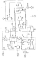
- the gas turbine 10 according to FIG. 1 consists in a known manner of an air compressor 11, one (or more) Combustion chambers 13 and a turbine part 12. Combustion gases are generated in the combustion chamber from compressed air and fuel and are expanded in the turbine to perform work.
- An air filter 14 is arranged in front of the air inlet of the air compressor 11, through which the air L is sucked in.
- the fuel B is supplied to the combustion chamber 13 via the fuel cleaning device 15.
- the exhaust line 16 is connected to an additional burner 17, to which cleaned fuel is also supplied.
- Oxygen which may be contained in the exhaust gases, is converted in the additional burner 17.
- the exhaust gases leaving the additional burner 17 are fed to the waste heat boiler 18, which is a heat exchanger.
- the exhaust gases give off heat to the heating coil 19 of a steam cycle.
- the heating coils 19 consist of feed water preheaters, boiler tubes and steam superheaters, with a steam drum - omitted in the drawing - being interposed.
- an afterburning device 20 is provided which converts the rest of oxygen.
- the exhaust gases are then fed to the manifold 23 via a gas cooler 21 and a gas cleaning device 22.
- the heating coil 19 is part of the steam circuit, which contains the steam turbines 24 and 25 in parallel. Each turbine 24 or 25 is followed by a condenser 26 or 27, which is connected via a return line 28 to the inlet of the heating coil 19. The outlet of the heating coil 19 is connected via the steam line 30 to the inlets of the steam turbines 24 and 25.
- the gas turbine 10 forms, together with the additional burner 17 and the waste heat boiler 18, the thermal energy generation system 10, 17, 18.
- the afterburning device 20 is connected to the waste heat boiler, so that the temperature of the exhaust gas corresponds to the optimum temperature for the afterburning reaction. Following the afterburning, the exhaust gas returns to the waste heat boiler 18 for further cooling.
- the shaft of the steam turbine 25 drives the air compressor 31 of the air separation unit 32.
- the suction line of the air compressor 31 is connected to an air inlet L via an air filter 33.
- the air separation unit 32 contains, in addition to the air compressor 31, the air separation part 34, one outlet O of which supplies the oxygen fraction and the other outlet N of which the nitrogen fraction N of the air.
- the nitrogen fraction N is fed to the manifold 23 and mixed there with the flue gas.
- the manifold 23 leads to a compressor 35, which is driven by the output shaft of the gas turbine 10 and compresses the mixture consisting of exhaust gas and nitrogen in a first stage.
- the mixture is compressed in a further compressor 36 in a second stage and then fed to the product outlet P.
- the compressor 36 is driven by the output shaft of the steam turbine 24.
- a portion of the mixture of exhaust gas and inert gas can be fed from the compressor 35 to the combustion chamber 13 via the line 37 shown in broken lines in order to enable combustion in the combustion chamber in the reaction zone and to increase the temperature in the reaction zone of the combustion chamber.
- the Line 37 leads into the flame-distant end of the combustion chamber 13 or into the connection between the combustion chamber 13 and the turbine part 12.
- a portion of the cooled exhaust gases is branched off behind the gas cooler 21 and introduced into the air intake line of the air compressor 11 via line 38.
- the gas turbine 10 thus draws in a mixture of air and exhaust gas in order to reduce the excess air or to replace part of the mass flow required with exhaust gases.
- the thermal energy generation system 10, 17, 18 delivers mechanical energy to the compressor 35 and on the other hand thermal energy to the steam circuit in order to provide the injection gas generated at the required pressure P and to the compressor 31 of the air separation system 32 to operate.
- the various measures given can ensure that the mixture consisting of a mixture of exhaust gases and nitrogen is free of oxygen. This is based on a complete conversion of the sucked-in oxygen in the different combustion chambers and by suitable design of the combustion chambers.
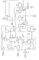
- FIGS. 2 to 4 are largely the same as that of Fig. 1, so that the following explanations are limited to the respective differences.
- the nitrogen fraction N of the air separation plant 32 is not input into the intake side of the compressor 35, but rather into an intermediate stage of this compressor. This is because the air separation unit supplies the nitrogen fraction with a superatmospheric pressure. In this case, the nitrogen is mixed with the exhaust gases in the compressor 35.
- FIG. 3 is particularly suitable if an air separation plant is used which supplies the nitrogen fraction with a higher residual oxygen content.
- air separation plants operate according to a relatively simple process and they are less expensive than air separation plants which supply the nitrogen with high purity.
- the nitrogen fraction N is not supplied to a manifold, but rather to the line 38 which leads to the inlet of the air compressor 11 of the gas turbine 10.
- the nitrogen fraction with the residual oxygen content mixes with the intake air L and takes part in the combustion reaction.
- the oxygen throughput of the gas turbine is reduced, since part of the sucked-in gases consists of nitrogen.
- the nitrogen passes through the gas turbine 10 and is subsequently found in the exhaust gases.
- a portion of the nitrogen supplied to line 38 may be diverted to be supplied to compressor 35.
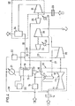
- an air separation plant 32 is again used, which supplies the nitrogen or a nitrogen-rich fraction with residual oxygen under superatmospheric pressure.
- the nitrogen fraction N is fed to the combustion chamber 13 of the gas turbine 10, either an inlet on the flame side (solid line) or an inlet remote from the flame or the connecting line between the combustion chamber 13 and the turbine part 12 (dash-dotted line).
- the fraction is injected near the flame if the fraction contains oxygen.
- the proportion of oxygen is converted during combustion.
- the injection takes place in the area far from the flame when the nitrogen fraction is essentially pure.
- the turbine inlet temperature is significantly reduced by injecting inert gas. In any case, the nitrogen that is supplied to the combustion chamber 13 gets into the exhaust gases.
- Fig. 5 shows an embodiment in which this water is used to be discharged as steam condensate D in addition to the product gas P.
- the water W is discharged from an intercooler 39 of the compressor 35 and fed to an evaporator 38, which is contained in the waste heat boiler 18 in addition to the heating coils 19.
- the vapor D leaving the evaporator 38 can be pressed into the petroleum deposit in addition to the product gas P, or can be used for other purposes in the oil field.
- the water W coming from the intercooler 39 is also supplied to the evaporator 38, which water is obtained behind the cooler 21. In this way, this is ent in the combustion of hydrocarbons standing water is first converted into steam and then discharged.
- FIG. 6 is the same as that of FIG. 5, except that the vapor leaving the evaporator 38 is not removed but is returned to the combustion chamber 13. In this case there is a closed water / steam cycle in which demineralized circulates.
- the steam supplied to the combustion chamber 13 supplements the fuel / air volume, so that the gas turbine 10 can be operated with a lower air throughput.
- a special separating tank for separating gas and condensate is provided in practice instead of the branching shown.
- a combined device with cooler and separator function can also be used.
- blowing steam into the gas turbine brings not only an improvement in efficiency, but also further advantages: the injected steam can be used like recirculated exhaust gas or generated gas mixture.
- the combustion temperature in the combustion chamber 13 can be increased.
- Subsequent mixing with the injected steam reduces the turbine inlet temperature to the permissible level.
- Steam injection can be used to optimally adapt the performance of the steam and gas turbines to the compressors to be driven.
- the gas generation plant according to the invention can be adapted to different requirements, namely with regard to the use of all known air separation plants (whether they release pure nitrogen or nitrogen containing residual oxygen, atmospheric or pressurized nitrogen) and with regard to different gas quantities and discharge pressures (be it that one or more housing compression systems are required or different types of compressors, such as axial, radial or piston compressors to be combined) by the performance of the gas turbines, steam turbines or other engines on the one hand and the work machine on the other hand can be coordinated.
Abstract
Description
Die Erfindung betrifft eine Vorrichtung nach dem Gherbegriff des Patentanspruchs 1.The invention relates to a device according to the preamble of claim 1.
Es ist bekannt, zur Steigerung der Ausbeute von Öllagerstätten bestimmte Gase, wie z.B. Stickstoff oder ein durch Verbrennen von Kohlenwasserstoffen gewonnenes Gemisch aus Stickstoff und Kohlendioxid einzupressen. Das Gas muß in großen Mengen kostengünstig erzeugt werden können.It is known to use certain gases such as e.g. Nitrogen or a mixture of nitrogen and carbon dioxide obtained by burning hydrocarbons. The gas must be able to be produced inexpensively in large quantities.
Konventionelle Anlagen zur Erzeugung von Verbrennungsgas für den genannten Zweck bestehen in der Regel aus einer Brennkammer und einer Kühleinrichtung für das in der Brennkammer erzeugte Abgas. Es ist auch bekannt, als Verbrennungseinrichtung eine Gasturbine mit geschlossenem Kreislauf zu verwenden, die dazu dient, einen Kompressor für die Abgase anzutreiben (DE-OS 32 28 091). Obwohl hierbei die mechanische Energie der das Abgas erzeugenden Gasturbine ausgenutzt wird, um ein weiteres Aggregat anzutreiben, ist die Gasausbeute im Verhältnis zur aufgewandten Energie immer noch sehr gering.Conventional systems for the production of combustion gas for the stated purpose generally consist of a combustion chamber and a cooling device for the exhaust gas generated in the combustion chamber. It is also known to use a gas turbine with a closed circuit as the combustion device, which serves to drive a compressor for the exhaust gases (DE-OS 32 28 091). Although here the mechanical energy of the gas turbine generating the exhaust gas is used to To drive another unit, the gas yield in relation to the energy used is still very low.
Es ist ferner bekannt, für den genannten Zweck Stickstoff zu verwenden, der durch Zerlegen von Luft in Sauerstoff und Stickstoff mit einer Luftzerlegungsanlage gewonnen wird. Dabei ist der Energiebedarf zur Erzeugung einer Nonnvoluneneinheit Stickstoff geringer als zur Erzeugung einer Normvolumeneinheit Verbrennungsgas nach dem zuvor beschriebenen Verfahren. Andererseits erfordert eine Luftzerlegungsanlage höhere Investitionen als eine Verbrennungsgasanlage gleicher Kapazität.It is also known to use nitrogen for the stated purpose, which is obtained by separating air into oxygen and nitrogen using an air separation plant. The energy requirement for generating a nominal volume unit of nitrogen is lower than for generating a standard volume unit of combustion gas according to the previously described method. On the other hand, an air separation plant requires higher investments than a combustion gas plant of the same capacity.
Stickstoff oder aus Verbrennungsgas gewonnenes Gemisch aus Stickstoff und Kohlendioxid wird in der Technik seit langem für sonstige Zwecke benutzt, besonders zum Inertisieren von Anlagen, die brennbare Stoffe verarbeiten oder überhaupt zum Verdrängen oder Verdünnen des Luftsauerstoffes. Bekannte Vorrichtungen zur Erzeugung dieser Gase wurden vorwiegend als Inertgaserzeuger entwickelt. Für kleinere Mengen wird wegen der geringeren Investitionskosten die Anwendung von Verbrennungsinertgas (Abgas) bevorzugt, wenn der spezielle Anwendungsfall nicht reinen Stickstoff verlangt. Für größere Mengen, insbesondere, wenn nicht nur gelegentlicher sondern kontinuierlicher Bedarf besteht, ist die Luftzerlegung wegen des geringeren Energieverbrauchs pro erzeugter Inertgasmenge vorteilhafter.Nitrogen or a mixture of nitrogen and carbon dioxide obtained from combustion gas has long been used in technology for other purposes, especially for inerting plants which process combustible substances or at all for displacing or diluting atmospheric oxygen. Known devices for generating these gases have mainly been developed as inert gas generators. For smaller quantities, the use of combustion inert gas (exhaust gas) is preferred due to the lower investment costs, if the special application does not require pure nitrogen. For larger quantities, especially if there is not only occasional but continuous need, air separation is more advantageous because of the lower energy consumption per quantity of inert gas generated.
Der Erfindung liegt die Aufgabe zugrunde, eine Vorrichtung der im Oberbegriff des Patentanspruchs 1 angegebenen Art zu schaffen, die es ermöglicht, große Mengen von Injektionsgas kostengünstig und mit geringem Energieaufwand zu erzeugen. Die Lösung dieser Aufgabe erfolgt bei einer ersten Variante der Erfindung mit den im kennzeichnenden Teil des Patentanspruchs 1 angegebenen Merkmalen und bei einer zweiten Variante mit den im kennzeichnenden Teil des Anspruchs 2 angegebenen Merkmalen.The invention has for its object to provide a device of the type specified in the preamble of claim 1, which makes it possible to produce large amounts of injection gas inexpensively and with little energy. This object is achieved in a first variant of the invention with the features specified in the characterizing part of patent claim 1 and in a second variant with the features specified in the characterizing part of claim 2.
Die erfindungsgemäße Vorrichtung stellt eine Kombination aus einer thermischen Energieerzeugungsanlage und einer Luftzerlegungsanlage dar. Dabei erzeugt die thermische Energieerzeugungsanlage die Energie für den Betrieb der Luftzerlegungsanlage. Jede der beiden Anlagen kann für den jeweiligen Anwendungsfall optimiert werden. Die erfindungsgemäße Vorrichtung hat einen deutlich geringeren Energiebedarf als wenn dieselbe Gasmenge in Form von Stickstoff mit einer Luftzerlegungsanlage erzeugt würde. Auch hinsichtlich der Investitionskosten ist die erfindungsgemäße kombinierte Vorrichtung günstiger als eine Luftzerlegungsanlage, die dieselbe Gasmenge ausschließlich mit einer thermischen Energieerzeugungsanlage bereitstellt. Der Vorteil des geringeren Energieverbrauchs ergibt sich bereits dann, wenn das erzeugte Gasgemisch (z.B. zur Verwendung als Inertgas) drucklos abgegeben wird, er ist jedoch noch ausgeprägter, wenn das Gasgemisch verdichtet abgegeben wird, wie es zur Entölung von Erdöllagerstätten immer erforderlich ist. In diesem Fall kann auch die Verdichtung des Gasgemisches mit der von der thermischen Energieerzeugungsanlage bereitgestellten Energie erfolgen, wie es in den Patentansprüchen 4 und 5 angegeben ist.The device according to the invention represents a combination of a thermal energy generation plant and an air separation plant. The thermal energy generation plant generates the energy for the operation of the air separation plant. Each of the two systems can be optimized for the respective application. The device according to the invention has a significantly lower energy requirement than if the same amount of gas in the form of nitrogen were generated with an air separation plant. Also in terms of investment costs, the combined device according to the invention is cheaper than an air separation plant that provides the same amount of gas exclusively with a thermal energy generation plant. The advantage of lower energy consumption already arises when the gas mixture generated is released without pressure (e.g. for use as an inert gas), but it is even more pronounced when the gas mixture is discharged in a compressed manner, as is always necessary for the deoiling of oil deposits. In this case, the gas mixture can also be compressed with the energy provided by the thermal energy generation system, as specified in patent claims 4 and 5.
Gasturbinen, die als thermische Energieerzeugungsanlage benutzt werden können, werden mit hohem Luftüberschuß gefahren. Das Verbrennungsgas (Abgas) einer normalen Gasturbine ist daher zur Gewinnung eines Stickstoff/ Kohlendioxid-Gemisches nicht geeignet, weil. es zuviel Sauerstoff enthält. Nach Patentanspruch 6 wird das Problem dadurch gelöst, daß ein Teil der gekühlten Abgase zu der Gasturbine zurückgeführt wird, so daß die Gasturbine ein Gemisch aus Luft und Abgas ansaugt. Das Verhältnis Luft: Abgas kann so eingestellt werden, daß der in dem angesaugten Gasgemisch enthaltene Sauerstoff in der Brennkammer der Gasturbine restlos ungesetzt wird.Gas turbines that can be used as a thermal energy generation system are operated with a large excess of air. The combustion gas (exhaust gas) of a normal gas turbine is therefore unsuitable for obtaining a nitrogen / carbon dioxide mixture because. it too much Contains oxygen. According to claim 6, the problem is solved in that a part of the cooled exhaust gases is returned to the gas turbine, so that the gas turbine sucks in a mixture of air and exhaust gas. The air: exhaust gas ratio can be set so that the oxygen contained in the gas mixture drawn in is completely set in the combustion chamber of the gas turbine.
Eine andere Möglichkeit besteht darin, daß der Gasturbine ein Abhitze-Kessel mit Zusatzbrenner nachgeschaltet ist, wobei der restliche Sauerstoff in dem Zusatzbrenner umgesetzt wird. Infolge des hohen Luft- überschusses einer normalen Gasturbine muß ein überwiegender Anteil der Energieerzeugung auf den zusatzgefeuerten Abhitze-Kessel verlagert werden, um allen Sauerstoff zu beseitigen. Die Energieerzeugung als ganzes erhält somit eher den Charakter eines Dampfkessels mit vorgeschalteter Gasturbine. Durch Kombination der vorher beschriebenen Abgasrückführung mit einem zusatzbefeuerten Abhitzekessel kann das Verhältnis Gasturbinenleistung:Dampfturbinenleistung in jeder gewünschten Weise eingestellt und dadurch an die Leistungsaufnahme der verwendeten Maschinen angepaßt werden.Another possibility is that the gas turbine is followed by a waste heat boiler with an additional burner, the remaining oxygen being converted in the additional burner. As a result of the high air surplus of a normal gas turbine, a major part of the energy generation has to be shifted to the additional fired waste heat boiler in order to remove all oxygen. The generation of energy as a whole thus takes on the character of a steam boiler with an upstream gas turbine. By combining the previously described exhaust gas recirculation with an additional fired waste heat boiler, the ratio of gas turbine power: steam turbine power can be set in any desired manner and can thus be adapted to the power consumption of the machines used.
Wenn aller Sauerstoff innerhalb des Gasturbinenprozesses umgesetzt werden soll und hohe Anforderungen an die Reinheit des Gasgemisches gestellt werden, dann können gemäß Patentanspruch 8 verdichtete Abgas oder erzeugtes Gasgemisch in das flammenferne Ende der Brennkammer oder auch in den. Verbindungskanal zwischen Brennkammer und Turbine eingeblasen werden. Diese Maßnahme ermöglicht es, in der Brennkammer eine höhere Temperatur einzustellen als bei einer normalen Gasturbine, und dadurch die Verbrennungsreaktion zu begünstigen. Nach dem Vermischen des in der Brennkammer entstandenen Verbrennungsgases mit dem eingeblasenen Gas ist die Gastemperatur gerade so hoch wie für die Turbine zulässig ist. Bei den derzeitigen Gasturbinen kann diese Temperatur bis nahe 1000°C betragen.If all oxygen is to be implemented within the gas turbine process and high demands are placed on the purity of the gas mixture, then compressed exhaust gas or gas mixture produced can be placed in the flame-distant end of the combustion chamber or in the. Connection channel between the combustion chamber and turbine are blown. This measure makes it possible to set a higher temperature in the combustion chamber than in a normal gas turbine, and thereby favoring the combustion reaction. After mixing the combustion gas generated in the combustion chamber with the injected gas, the gas temperature is just as high as is permissible for the turbine. In current gas turbines, this temperature can be up to close to 1000 ° C.
Die Patentansprüche 10 und 11 beziehen sich auf Varianten, bei denen die Luftzerlegungsanlage die Stickstoff-Fraktion mit überatmosphärischem Druck liefert, wobei der Druck für die weitere Verdichtung oder zum Injizieren in die Brennkammer ausgenutzt wird.
Im folgenden werden unter Bezugnahme auf die Zeichnungen Ausführungsbeispiele der Erfindung näher erläutert.Exemplary embodiments of the invention are explained in more detail below with reference to the drawings.
Es zeigen:
- Fig. 1 ein Diagramm eines Ausführungsbeispiels der ersten Variante der Vorrichtung,
- Fig. 2 ein weiteres Ausführungsbeispiel der ersten Variante,
- Fig. 3 ein Ausführungsbeispiel der zweiten Variante,
- Fig. 4 ein weiteres Ausführungsbeispiel der zweiten Variante und
- Fig. 5 und 6 Ausführungsbeispiele mit zusätzlicher Dampferzeugung.
- 1 is a diagram of an embodiment of the first variant of the device,
- 2 shows another embodiment of the first variant,
- 3 shows an embodiment of the second variant,
- F ig. 4 shows a further exemplary embodiment of the second variant and
- 5 and 6 embodiments with additional steam generation.
Die Gasturbine 10 gemäß Fig. 1 besteht in bekannter Weise aus einem Luftkompressor 11, einer (oder mehreren) Brennkammern 13 und einem Turbinenteil 12. In der Brennkammer entstehen aus Druckluft und Brennstoff Verbrennungsgase, die in der Turbine arbeitsleistend entspannt werden. Vor dem Lufteinlaß des Luftkompressors 11 ist ein Luftfilter 14 angeordnet, durch den die Luft L angesaugt wird. Der Brennstoff B wird der Brennkammer 13 über die Brennstoff reinigungsvorrichtung 15 zugeführt.The
Da das Abgas der Gasturbine 10 noch unverbrauchten Sauerstoff enthalten kann, ist die Abgasleitung 16 mit einem Zusatzbrenner 17 verbunden, dem ebenfalls gereinigter Kraftstoff zugeführt wird. In dem Zusatzbrenner 17 wird Sauerstoff, der in den Abgasen enthalten sein kann, umgesetzt. Die den Zusatzbrenner 17 verlassenden Abgase werden dem Abhitzekessel 18 zugeführt, bei dem es sich um einen Wärmetauscher handelt. Die Abgase geben hier Wärme an die Heizschlange 19 eines Dampfkreislaufs ab. Die Heizschlangen 19 bestehen aus Speisewasservorwärmer, Siederohren und Dampfüberhitzer, wobei eine - in der Zeichnung weggelassene Dampftronmel dazwischengeschaltet ist. Zusätzlich ist noch eine Nachverbrennungsvorrichtung 20 vorgesehen, die den Rest Sauerstoff umsetzt. Die Abgase werden dann über einen Gaskühler 21 und eine Gasreinigungsvorrichtung 22 der Sammelleitung 23 zugeführt.Since the exhaust gas from the
Die Heizschlange 19 ist Bestandteil des Dampfkreislaufs, der die Dampfturbinen 24 und 25 in Parallelschaltung enthält. Jeder Turbine 24 bzw. 25 ist ein Kondensator 26 bzw. 27 nachgeschaltet, der über eine Rücklaufleitung 28 mit dem Einlaß der Heizschlange 19 verbunden ist. Der Auslaß der Heizschlange 19 ist über die Dampfleitung 30 mit den Einlässen der Dampfturbinen 24 und 25 verbunden.The
Die Gasturbine 10 bildet zusammen mit dem Zusatzbrenner 17 und der Abhitzekessel 18 die thermische Energieerzeugungsanlage 10, 17, 18. Die Nachverbrennungsvorrichtung 20 steht mit dem Abhitzekessel in Verbindung, derart daß die Temperatur des Abgases der optimalen Temperatur für die Nachverbrennungsreaktion entspricht. Im Anschluß an die Nachverbrennung geht das Abgas zur weiteren Kühlung in den Abhitzekessel 18 zurück.The
Die Welle der Dampfturbine 25 treibt den Luftkompressor 31 der Luftzerlegungsanlage 32. Die Ansaugleitung des Luftkompressors 31 ist über einen Luftfilter 33 mit einem Lufteinlaß L verbunden. Die Luftzerlegungsanlage 32 enthält außer dem Luftkompressor 31 den Luftzerlegungsteil 34, dessen einer Auslaß O die Sauerstoff-Fraktion und dessen anderer Auslaß N die Stickstoff-Fraktion N der Luft liefert. Die Stickstoff-Fraktion N wird der Sammelleitung 23 zugeführt und dort mit dem Rauchgas vermischt.The shaft of the
Die Sammelleitung 23 führt zu einem Kompressor 35, der von der Ausgangswelle der Gasturbine 10 angetrieben wird und das aus Abgas und Stickstoff bestehende Gemisch in einer ersten Stufe verdichtet. Das Gemisch wird in einem weiteren Kompressor 36 in einer zweiten Stufe verdichtet und anschließend dem Produktauslaß P zugeführt. Der Kompressor 36 wird von der Ausgangswelle der Dampfturbine 24 angetrieben.The manifold 23 leads to a
über die strichpunktiert dargestellte Leitung 37 kann ein Teil des Gemisches aus Abgas und Inertgas von dem Kompressor 35 der Brennkammer 13 zugeführt werden, um in der Reaktionszone der Brennkammer eine sauerstoffreichere Verbrennung zu ermöglichen und die Temperatur in der Reaktionszone der Brennkammer zu erhöhen. Die Leitung 37 führt in das flammenferne Ende der Brennkammer 13 oder in die Verbindung zwischen Brennkammer 13 und Turbinenteil 12 hinein.A portion of the mixture of exhaust gas and inert gas can be fed from the
Ferner wird hinter dem Gaskühler 21 ein Teil der gekühlten Abgase abgezweigt und über Leitung 38 in die Luftansaugleitung des Luftkompressors 11 eingeführt. Die Gasturbine 10 saugt somit ein Gemisch aus Luft und Abgas an, um den Luftüberschuß zu verringern bzw. um einen Teil des benötigten Massenstromes durch Abgase zu ersetzen.Furthermore, a portion of the cooled exhaust gases is branched off behind the
Aus der obigen Beschreibung ergibt sich, daß die thermische Energieerzeugungsanlage 10,17,18 einerseits mechanische Energie an den Kompressor 35 und andererseits thermische Energie an den Dampfkreislauf abgibt, um das erzeugte Injektionsgas mit dem erforderlichen Druck P bereitzustellen, und um den Kompressor 31 der Luftzerlegungsanlage 32 zu betreiben. Durch die verschiedenen angegebenen Maßnahmen kann erreicht werden, daß das aus einer Mischung von Abgasen und Stickstoff bestehende Gemisch frei von Sauerstoff ist. Dies beruht auf einer vollständigen Umsetzung des angesaugten Sauerstoffs in den verschiedenen Brennräumen und durch geeignete Ausgestaltung der Brennräume.From the above description it follows that the thermal
Eine Vergleichsberechnung für die Erzeugung von 200.000 m Gas pro Stunde ergibt folgendes Verhältnis:
- a:b:c:=975:750:600.
- a: b: c: = 975: 750: 600.
Hierin stellt a den Energieaufwand dar, der sich ergibt, wenn die gesamte Gasmenge aus Abgas besteht, b den Energieaufwand, wenn die gesamte Gasmenge aus Stickstoff besteht, der durch Luftzerlegung gewonnen wird, und c ist der Energieaufwand bei der Herstellung des Gasgemisches mit der beschriebenen Vorrichtung.Herein represents a the energy expenditure which results when the total gas quantity consists of exhaust gas, b the energy expenditure when the entire gas quantity consists of nitrogen, which is obtained by air separation, and c is the energy expenditure in the production of the gas mixture with the device described.
Die Ausführungsbeispiele der Fign. 2 bis 4 gleichen weitgehend demjenigen von Fig. 1, so daß die nachfolgenden Erläuterungen sich auf die jeweiligen Unterschiede beschränken.The exemplary embodiments of FIGS. 2 to 4 are largely the same as that of Fig. 1, so that the following explanations are limited to the respective differences.
Bei dem Ausführungsbeispiel der Fig. 2 wird die Stick-stoff-Fraktion N der Luftzerlegungsanlage 32 nicht in die Ansaugseite des Kompressors 35 eingegeben, sondern in eine Zwischenstufe dieses Kompressors. Dies liegt daran, daß die Luftzerlegungsanlage die Stickstoffraktion mit einem überatmosphärischen Druck liefert. In diesem Fall erfolgt die Vermischung des Stickstoffs mit den Abgasen in dem Kompressor 35.In the exemplary embodiment in FIG. 2, the nitrogen fraction N of the
Die Ausführungsform der Fig. 3 ist dann besonders geeignet, wenn eine Luftzerlegungsanlage verwendet wird, die die Stickstoff-Fraktion mit höherem Rest-Sauerstoffgehalt liefert. Solche Luftzerlegungsanlagen arbeiten nach einem relativ einfachen Verfahren und sie sind kostengünstiger als Luftzerlegungsanlagen, die den Stickstoff mit hoher Reinheit liefern. Gemäß Fig. 3 wird die Stickstoff-Fraktion N nicht einer Sammelleitung zugeführt, sondern der Leitung 38, die zu dem Einlaß des Luftkompressors 11 der Gasturbine 10 führt. Die Stickstoff-Fraktion mit dem Restsauerstoffgehalt vermischt sich mit der angesaugten Luft L und nimmt an der Verbrennungsreaktion teil. Dadurch wird der Sauerstoffdurchsatz der Gasturbine verrinert, indem ein Teil der angesaugten Gase aus Stickstoff besteht. Der Stickstoff durchläuft die Gasturbine 10 und findet sich nachfolgend in den Abgasen wieder. Ein Teil des Stickstoffs, der der Leitung 38 zugeführt wird, kann abgezweigt werden, um dem Kompressor 35 zugeführt zu werden.The embodiment of FIG. 3 is particularly suitable if an air separation plant is used which supplies the nitrogen fraction with a higher residual oxygen content. Such air separation plants operate according to a relatively simple process and they are less expensive than air separation plants which supply the nitrogen with high purity. 3, the nitrogen fraction N is not supplied to a manifold, but rather to the
Bei dem Ausführungsbeispiel der Fig. 4 wird wiederum eine Luftzerlegungsanlage 32 benutzt, die den Stickstoff oder eine stickstoffreiche Fraktion mit RestSauerstoff unter überatmosphärischem Druck liefert. Die Stickstoff-Fraktion N wird hierbei der Brennkammer 13 der Gasturbine 10 zugeführt und zwar entweder einem flammenseitigen Einlaß (durchgezogene Linie) oder einem flamraenfernen Einlaß bzw. der Verbindungsleitung zwischen Brennkammer 13 und Turbinenteil 12 (strichpunktierte Linie). Die Injektion der Fraktion erfolgt in Flammennähe, wenn die Fraktion einen Sauerstoffanteil enthält. Der Sauerstoffanteil wird bei der Verbrennung umgesetzt. Dagegen erfolgt die Injektion im flammenfernen Bereich, wenn die Stickstoff-Fraktion im wesentlichen rein ist. Durch das Injizieren von Inertgas wird die Turbineneinlaßtemperatur wesentlich herabgesetzt. In jedem Fall gelangt der Stickstoff, der der Brennkammer 13 zugeführt wird, in die Abgase.In the embodiment of FIG. 4, an
Bei der Verbrennung von Kohlenwasserstoffen entsteht Wasser, das hinter dem Kühler 21 und hinter dem Zwischenkühler des Kompressors 35 anfällt. Fig. 5 zeigt ein Ausführungsbeispiel, bei dem dieses Wasser benutzt wird, um als Dampfkondensat D zusätzlich zu dem Produktgas P abgeführt zu werden. Aus einem Zwischenkühler 39 des Kompressors 35 wird das Wasser W abgeführt und einem Verdampfer 38 zugeführt, der zusätzlich zu den Heizschlangen 19 im Abhitzekessel 18 enthalten ist. Der den Verdampfer 38 verlassende Dampf D kann zusätzlich zu dem Produktgas P in die Erdöllagerstätte eingepreßt werden, oder für sonstige Zwecke im Ölfeld Verwendung finden. Dem Verdampfer 38 wird außerdem vom Zwischenkühler 39 kommenden Wasser auch das Wasser W zugeführt, das hinter dem Kühler 21 anfällt. Auf diese Weise wird das bei der Verbrennung der Kohlenwasserstoffe entstehende Wasser zunächst in Dampf umgesetzt und anschließend abgeführt.When hydrocarbons are burned, water is produced which is produced behind the cooler 21 and behind the intercooler of the
Das Ausführungsbeispiel der Fig. 6 gleicht demjenigen der Fig. 5, mit Ausnahme der Tatsache, daß der den Verdampfer 38 verlassende Dampf nicht abgeführt, sondern in die Brennkammer 13 zurückgeführt wird. In diesem Fall existiert ein geschlossener Wasser/Dampf-Kreislauf, in dem demineralisiertes zirkuliert. Der der Brennkammer 13 zugeführte Dampf ergänzt das Brennstoff/Luft-Volumen, so daß die Gasturbine 10 mit geringerem Luftdurchsatz betrieben werden kann.The embodiment of FIG. 6 is the same as that of FIG. 5, except that the vapor leaving the
In den Fig. 5 und 6 wird in der Praxis anstelle der dargstellten Leitungsverzweigung ein besonderer Abscheidebehälter zum Trennen von Gasund Kondensat vorgesehen. Es kann auch ein kombiniertes Gerät mit Kühler-und Abscheider-Funktion benutzt werden.5 and 6, a special separating tank for separating gas and condensate is provided in practice instead of the branching shown. A combined device with cooler and separator function can also be used.
In Verbindung mit der Gaserzeugungsvorrichtung bringt das Einblasen von Dampf in die Gasturbine neben einer Verbesserung des Wirkungsgrades noch weitere Vorteile: Der eingeblasene Dampf kann wie rückgeführtes Abgas bzw. erzeugtes Gasgemisch verwendet werden. Die Verbrennungstemperatur in der Brennkammer 13 kann erhöht werden. Durch anschließendes Vermischen mit dem eingeblasenen Dampf wird die Turbineneintrittstemperatur auf die zulässige Höhe reduziert. In dem man den einzublasenden Dampf im Abhitzekessel 18 erzeugt, entzieht man die dafür nötige Wärme dem Dampfkreislauf. Es wird also Leistung von den Dampfturbinen zur Gasturbine verlagert. Die Dampfeinblasung kann dazu verwendet werden, die Leistungen der Dampf- und Gasturbinen optimal an die anzutreibenden Kompressoren anzupassen.In connection with the gas generating device, blowing steam into the gas turbine brings not only an improvement in efficiency, but also further advantages: the injected steam can be used like recirculated exhaust gas or generated gas mixture. The combustion temperature in the
Durch Kombination der Merkmale der verschiedenen Abwandlungen kann die erfindungsgemäße Gaserzeugungsanlage an unterschiedliche Erfordernisse angepaßt werden, nämlich hinsichtlich des Einsatzes aller bekannten Luftzerlegungsanlagen' (sei es daß diese reinen oder Restsauerstoff enthaltenden Stickstoff, atmosphärischen oder unter Überdruck stehenden Stickstoff abgeben) und hinsichtlich verschiedener Gasmengen und Abgabedrücke (sei es daß ein oder mehrgehäusige Verdichtungsanlagen erforderlich sind oder verschiedene Verdichtertypen, wie Axial-, Radial- oder Kolbenkompressoren zu kombinieren sind) indem die Leistungen der Gasturbinen, Dampfturbinen oder sonstigen Kraftmaschinen einerseits und der Arbeitsmaschine andererseits aufeinander abgestimmt werden können.By combining the features of the various modifications, the gas generation plant according to the invention can be adapted to different requirements, namely with regard to the use of all known air separation plants (whether they release pure nitrogen or nitrogen containing residual oxygen, atmospheric or pressurized nitrogen) and with regard to different gas quantities and discharge pressures (be it that one or more housing compression systems are required or different types of compressors, such as axial, radial or piston compressors to be combined) by the performance of the gas turbines, steam turbines or other engines on the one hand and the work machine on the other hand can be coordinated.
Claims (13)
dadurch gekennzeichnet,
daß eine Luftzerlegungsanlage (32) mit der thermischen Energieerzeugungsanlage (10,17,18) derart gekoppelt ist, daß diese die Energie für den Antrieb der Luftzerlegungsanlage (32) liefert und daß eine Stickstoff-Fraktion (N) der Luftzerlegungsanlage (32) und mindestens ein Teil des Abgases einer gemeinsamen Sammeleinrichtung (23) zugeführt werden.1. Device for generating injection gas, preferably for driving petroleum out of deposits, with a thermal energy generation system (10, 17, 18, 19, 24-29) which is fed with fuel (B) and generates exhaust gases,
characterized,
that an air separation plant (32) is coupled to the thermal energy generation plant (10, 17, 18) in such a way that it supplies the energy for driving the air separation plant (32) and that a nitrogen fraction (N) of the air separation plant (32) and at least part of the exhaust gas is fed to a common collecting device (23).
Applications Claiming Priority (2)
| Application Number | Priority Date | Filing Date | Title |
|---|---|---|---|
| DE19843418699 DE3418699A1 (en) | 1984-05-19 | 1984-05-19 | DEVICE FOR GENERATING INJECTION GAS, PREFERRED FOR DRIVING OIL OUT OF WAREHOUSE |
| DE3418699 | 1984-05-19 |
Publications (2)
| Publication Number | Publication Date |
|---|---|
| EP0162368A2 true EP0162368A2 (en) | 1985-11-27 |
| EP0162368A3 EP0162368A3 (en) | 1986-11-12 |
Family
ID=6236328
Family Applications (1)
| Application Number | Title | Priority Date | Filing Date |
|---|---|---|---|
| EP85105564A Withdrawn EP0162368A3 (en) | 1984-05-19 | 1985-05-07 | Injection gas-generating device, particularly for charging mineral oil from its underground reservoirs |
Country Status (3)
| Country | Link |
|---|---|
| EP (1) | EP0162368A3 (en) |
| DE (1) | DE3418699A1 (en) |
| NO (1) | NO851960L (en) |
Cited By (7)
| Publication number | Priority date | Publication date | Assignee | Title |
|---|---|---|---|---|
| EP0592059A1 (en) * | 1992-10-07 | 1994-04-13 | MANNESMANN Aktiengesellschaft | Process and system for compressing a gas |
| WO1999064719A2 (en) * | 1998-05-29 | 1999-12-16 | Naturkraft As | Process of preparing a gas composition and use thereof |
| WO2002103157A1 (en) * | 2001-06-15 | 2002-12-27 | The Petroleum Oil And Gas Corporation Of South Africa (Proprietary) Limited | Process for the recovery of oil from a natural oil reservoir |
| WO2005024188A2 (en) * | 2003-09-11 | 2005-03-17 | Ormat Technologies Inc. | Method of and apparatus for pressurizing gas flowing in a pipeline |
| FR2906879A1 (en) * | 2007-02-06 | 2008-04-11 | Air Liquide | Installation for producing a mixture of nitrogen and carbon dioxide for injection into a subterranean hydrocarbon reservoir comprises an air separator, an oxygen consumption unit, a carbon dioxide separator and a mixer |
| FR2938635A1 (en) * | 2008-11-18 | 2010-05-21 | Air Liquide | Oxygen and fluid i.e. water, producing method, involves sending compressed air to cryogenic distillation air separation apparatus, and sending water for assisted recovery of hydrocarbon e.g. petrol, after vaporization of water |
| WO2014137647A1 (en) * | 2013-03-08 | 2014-09-12 | Exxonmobil Upstream Research Company | Processing exhaust for use in enhanced oil recovery |
Families Citing this family (1)
| Publication number | Priority date | Publication date | Assignee | Title |
|---|---|---|---|---|
| US7874141B2 (en) * | 2007-11-16 | 2011-01-25 | General Electric Company | Auxiliary fluid source for an EGR purge system |
Citations (6)
| Publication number | Priority date | Publication date | Assignee | Title |
|---|---|---|---|---|
| US3579308A (en) * | 1969-09-25 | 1971-05-18 | Inert Gas Corp | Apparatus for manufacturing high pressure inert gas |
| US4344486A (en) * | 1981-02-27 | 1982-08-17 | Standard Oil Company (Indiana) | Method for enhanced oil recovery |
| GB2117053A (en) * | 1982-02-18 | 1983-10-05 | Boc Group Plc | Gas turbines and engines |
| US4434613A (en) * | 1981-09-02 | 1984-03-06 | General Electric Company | Closed cycle gas turbine for gaseous production |
| GB2140873A (en) * | 1983-06-03 | 1984-12-05 | Gen Electric | Closed-cycle gas turbine chemical processor |
| EP0127825A2 (en) * | 1983-06-03 | 1984-12-12 | Siemens Aktiengesellschaft | Integrated coal gasification power plant |
-
1984
- 1984-05-19 DE DE19843418699 patent/DE3418699A1/en not_active Withdrawn
-
1985
- 1985-05-07 EP EP85105564A patent/EP0162368A3/en not_active Withdrawn
- 1985-05-15 NO NO851960A patent/NO851960L/en unknown
Patent Citations (6)
| Publication number | Priority date | Publication date | Assignee | Title |
|---|---|---|---|---|
| US3579308A (en) * | 1969-09-25 | 1971-05-18 | Inert Gas Corp | Apparatus for manufacturing high pressure inert gas |
| US4344486A (en) * | 1981-02-27 | 1982-08-17 | Standard Oil Company (Indiana) | Method for enhanced oil recovery |
| US4434613A (en) * | 1981-09-02 | 1984-03-06 | General Electric Company | Closed cycle gas turbine for gaseous production |
| GB2117053A (en) * | 1982-02-18 | 1983-10-05 | Boc Group Plc | Gas turbines and engines |
| GB2140873A (en) * | 1983-06-03 | 1984-12-05 | Gen Electric | Closed-cycle gas turbine chemical processor |
| EP0127825A2 (en) * | 1983-06-03 | 1984-12-12 | Siemens Aktiengesellschaft | Integrated coal gasification power plant |
Cited By (18)
| Publication number | Priority date | Publication date | Assignee | Title |
|---|---|---|---|---|
| EP0592059A1 (en) * | 1992-10-07 | 1994-04-13 | MANNESMANN Aktiengesellschaft | Process and system for compressing a gas |
| CN1053258C (en) * | 1992-10-07 | 2000-06-07 | 哈罗德·文策尔 | Method and apparatus for compression of gas medium |
| WO1999064719A2 (en) * | 1998-05-29 | 1999-12-16 | Naturkraft As | Process of preparing a gas composition and use thereof |
| WO1999064719A3 (en) * | 1998-05-29 | 2001-06-07 | Naturkraft As | Process of preparing a gas composition and use thereof |
| US6595291B1 (en) | 1998-05-29 | 2003-07-22 | Naturkraft As | Process of preparing a gas composition and use thereof |
| WO2002103157A1 (en) * | 2001-06-15 | 2002-12-27 | The Petroleum Oil And Gas Corporation Of South Africa (Proprietary) Limited | Process for the recovery of oil from a natural oil reservoir |
| EA005363B1 (en) * | 2001-06-15 | 2005-02-24 | Дзе Петролеум Ойл Энд Гэс Корпорейшн Оф Саут Эфрика (Пропрайэтери) Лимитед | Process for the recovery of oil from national oil reservoir |
| US7077202B2 (en) | 2001-06-15 | 2006-07-18 | The Petroleum Oil and Gas Corporation of South Africa (Proprietary Limited) | Process for the recovery of oil from a natural oil reservoir |
| WO2005024188A3 (en) * | 2003-09-11 | 2005-04-21 | Ormat Technologies Inc | Method of and apparatus for pressurizing gas flowing in a pipeline |
| WO2005024188A2 (en) * | 2003-09-11 | 2005-03-17 | Ormat Technologies Inc. | Method of and apparatus for pressurizing gas flowing in a pipeline |
| US7950214B2 (en) | 2003-09-11 | 2011-05-31 | Ormat Technologies Inc. | Method of and apparatus for pressurizing gas flowing in a pipeline |
| FR2906879A1 (en) * | 2007-02-06 | 2008-04-11 | Air Liquide | Installation for producing a mixture of nitrogen and carbon dioxide for injection into a subterranean hydrocarbon reservoir comprises an air separator, an oxygen consumption unit, a carbon dioxide separator and a mixer |
| FR2938635A1 (en) * | 2008-11-18 | 2010-05-21 | Air Liquide | Oxygen and fluid i.e. water, producing method, involves sending compressed air to cryogenic distillation air separation apparatus, and sending water for assisted recovery of hydrocarbon e.g. petrol, after vaporization of water |
| WO2014137647A1 (en) * | 2013-03-08 | 2014-09-12 | Exxonmobil Upstream Research Company | Processing exhaust for use in enhanced oil recovery |
| CN105189942A (en) * | 2013-03-08 | 2015-12-23 | 埃克森美孚上游研究公司 | Processing exhaust for use in enhanced oil recovery |
| AU2014226412B2 (en) * | 2013-03-08 | 2016-06-23 | Exxonmobil Upstream Research Company | Processing exhaust for use in enhanced oil recovery |
| US9784140B2 (en) | 2013-03-08 | 2017-10-10 | Exxonmobil Upstream Research Company | Processing exhaust for use in enhanced oil recovery |
| CN105189942B (en) * | 2013-03-08 | 2018-03-30 | 埃克森美孚上游研究公司 | Emission is handled to improve oil recovery |
Also Published As
| Publication number | Publication date |
|---|---|
| DE3418699A1 (en) | 1985-11-21 |
| NO851960L (en) | 1985-11-20 |
| EP0162368A3 (en) | 1986-11-12 |
Similar Documents
| Publication | Publication Date | Title |
|---|---|---|
| EP0150340B1 (en) | Method of operating a combined gas/steam turbine power plant | |
| DE602004011762T2 (en) | METHOD FOR OPERATING A GAS TURBINE GROUP | |
| CH666253A5 (en) | DEVICE FOR CHEMICAL PRODUCTION OF CARBON DIOXIDE. | |
| EP0076529B1 (en) | Nox reduction for gas turbines by water injection into the combustion chamber | |
| CH698466A2 (en) | Combustion system with gas turbine and oxygen source. | |
| EP0148973A2 (en) | Combined gas-turbine-steam turbine plant with preconnected coal gasification plant | |
| EP0311877A2 (en) | Method and cylinder head for admitting fuel to a piston engine | |
| DE3702654A1 (en) | METHOD FOR OPERATING A GAS TURBINE PLANT WITH LOW-VALUE FUEL | |
| EP0162368A2 (en) | Injection gas-generating device, particularly for charging mineral oil from its underground reservoirs | |
| DE60214174T2 (en) | METHOD AND APPARATUS FOR GENERATING ELECTRICAL ENERGY THROUGH A GAS TURBINE PROVIDED WITH AN AIR DECOMPOSITION PLANT | |
| DE60005580T2 (en) | Gas turbine engine | |
| EP0462458B1 (en) | Method to increase the compressor pressure ratio of a gas turbine plant | |
| DE3139209A1 (en) | "METHOD FOR OPERATING A COMBINED GAS-VAPOR TURBINE PLANT AND PLANT FOR CARRYING OUT THE METHOD | |
| DE2332698A1 (en) | PROCEDURE FOR OPERATING A GAS TURBINE SYSTEM AND GAS TURBINE SYSTEM EQUIPPED FOR THE PROCESS | |
| EP0137152B1 (en) | Method of operating a gas turbine plant combined with a fuel gasification plant | |
| DE112004000994T5 (en) | Method of obtaining ultra-low NOx emissions from gas turbines operating at high turbine inlet temperatures | |
| EP0597325A1 (en) | Method of compressor intercooling | |
| EP0272410A2 (en) | Steam generator with fluidised-bed combustion | |
| EP0916836A2 (en) | Device for admitting vapour to the intake air of a combustion engine | |
| DE3419560A1 (en) | Method for the operation of a gas turbine plant and plant for the method | |
| DE112006001974B4 (en) | Method for operating a gas turbine and gas turbine for carrying out the method | |
| EP0917620B1 (en) | Internal combustion engine with extended working cycle | |
| WO2002038927A1 (en) | Method for operating a gas turbine system, and a corresponding system | |
| DE2837714A1 (en) | Compact gas turbine unit - uses turbine exhaust to evaporate pressurised water, resulting steam being introduced in compressor outlet line to turbine | |
| DE3734959C2 (en) |
Legal Events
| Date | Code | Title | Description |
|---|---|---|---|
| PUAI | Public reference made under article 153(3) epc to a published international application that has entered the european phase |
Free format text: ORIGINAL CODE: 0009012 |
|
| AK | Designated contracting states |
Designated state(s): AT BE CH FR GB IT LI NL SE |
|
| PUAL | Search report despatched |
Free format text: ORIGINAL CODE: 0009013 |
|
| AK | Designated contracting states |
Kind code of ref document: A3 Designated state(s): AT BE CH FR GB IT LI NL SE |
|
| STAA | Information on the status of an ep patent application or granted ep patent |
Free format text: STATUS: THE APPLICATION IS DEEMED TO BE WITHDRAWN |
|
| 18D | Application deemed to be withdrawn |
Effective date: 19870513 |
|
| RIN1 | Information on inventor provided before grant (corrected) |
Inventor name: LEHMANN, ERICH, DIPL.-ING. |