EP0161809A1 - Overcoated recording elements having amorphous dye and binder optical recording layers - Google Patents
Overcoated recording elements having amorphous dye and binder optical recording layers Download PDFInfo
- Publication number
- EP0161809A1 EP0161809A1 EP85302603A EP85302603A EP0161809A1 EP 0161809 A1 EP0161809 A1 EP 0161809A1 EP 85302603 A EP85302603 A EP 85302603A EP 85302603 A EP85302603 A EP 85302603A EP 0161809 A1 EP0161809 A1 EP 0161809A1
- Authority
- EP
- European Patent Office
- Prior art keywords
- recording
- layer
- binder
- dye
- overcoat
- Prior art date
- Legal status (The legal status is an assumption and is not a legal conclusion. Google has not performed a legal analysis and makes no representation as to the accuracy of the status listed.)
- Granted
Links
Images

Classifications
-
- G—PHYSICS
- G11—INFORMATION STORAGE
- G11B—INFORMATION STORAGE BASED ON RELATIVE MOVEMENT BETWEEN RECORD CARRIER AND TRANSDUCER
- G11B7/00—Recording or reproducing by optical means, e.g. recording using a thermal beam of optical radiation by modifying optical properties or the physical structure, reproducing using an optical beam at lower power by sensing optical properties; Record carriers therefor
- G11B7/24—Record carriers characterised by shape, structure or physical properties, or by the selection of the material
- G11B7/241—Record carriers characterised by shape, structure or physical properties, or by the selection of the material characterised by the selection of the material
- G11B7/242—Record carriers characterised by shape, structure or physical properties, or by the selection of the material characterised by the selection of the material of recording layers
- G11B7/244—Record carriers characterised by shape, structure or physical properties, or by the selection of the material characterised by the selection of the material of recording layers comprising organic materials only
- G11B7/246—Record carriers characterised by shape, structure or physical properties, or by the selection of the material characterised by the selection of the material of recording layers comprising organic materials only containing dyes
-
- G—PHYSICS
- G11—INFORMATION STORAGE
- G11B—INFORMATION STORAGE BASED ON RELATIVE MOVEMENT BETWEEN RECORD CARRIER AND TRANSDUCER
- G11B7/00—Recording or reproducing by optical means, e.g. recording using a thermal beam of optical radiation by modifying optical properties or the physical structure, reproducing using an optical beam at lower power by sensing optical properties; Record carriers therefor
- G11B7/24—Record carriers characterised by shape, structure or physical properties, or by the selection of the material
- G11B7/241—Record carriers characterised by shape, structure or physical properties, or by the selection of the material characterised by the selection of the material
- G11B7/252—Record carriers characterised by shape, structure or physical properties, or by the selection of the material characterised by the selection of the material of layers other than recording layers
- G11B7/254—Record carriers characterised by shape, structure or physical properties, or by the selection of the material characterised by the selection of the material of layers other than recording layers of protective topcoat layers
- G11B7/2548—Record carriers characterised by shape, structure or physical properties, or by the selection of the material characterised by the selection of the material of layers other than recording layers of protective topcoat layers consisting essentially of inorganic materials
-
- G—PHYSICS
- G11—INFORMATION STORAGE
- G11B—INFORMATION STORAGE BASED ON RELATIVE MOVEMENT BETWEEN RECORD CARRIER AND TRANSDUCER
- G11B7/00—Recording or reproducing by optical means, e.g. recording using a thermal beam of optical radiation by modifying optical properties or the physical structure, reproducing using an optical beam at lower power by sensing optical properties; Record carriers therefor
- G11B7/24—Record carriers characterised by shape, structure or physical properties, or by the selection of the material
- G11B7/241—Record carriers characterised by shape, structure or physical properties, or by the selection of the material characterised by the selection of the material
- G11B7/252—Record carriers characterised by shape, structure or physical properties, or by the selection of the material characterised by the selection of the material of layers other than recording layers
- G11B7/257—Record carriers characterised by shape, structure or physical properties, or by the selection of the material characterised by the selection of the material of layers other than recording layers of layers having properties involved in recording or reproduction, e.g. optical interference layers or sensitising layers or dielectric layers, which are protecting the recording layers
-
- G—PHYSICS
- G11—INFORMATION STORAGE
- G11B—INFORMATION STORAGE BASED ON RELATIVE MOVEMENT BETWEEN RECORD CARRIER AND TRANSDUCER
- G11B7/00—Recording or reproducing by optical means, e.g. recording using a thermal beam of optical radiation by modifying optical properties or the physical structure, reproducing using an optical beam at lower power by sensing optical properties; Record carriers therefor
- G11B7/24—Record carriers characterised by shape, structure or physical properties, or by the selection of the material
- G11B7/241—Record carriers characterised by shape, structure or physical properties, or by the selection of the material characterised by the selection of the material
- G11B7/252—Record carriers characterised by shape, structure or physical properties, or by the selection of the material characterised by the selection of the material of layers other than recording layers
- G11B7/258—Record carriers characterised by shape, structure or physical properties, or by the selection of the material characterised by the selection of the material of layers other than recording layers of reflective layers
- G11B7/2585—Record carriers characterised by shape, structure or physical properties, or by the selection of the material characterised by the selection of the material of layers other than recording layers of reflective layers based on aluminium
-
- Y—GENERAL TAGGING OF NEW TECHNOLOGICAL DEVELOPMENTS; GENERAL TAGGING OF CROSS-SECTIONAL TECHNOLOGIES SPANNING OVER SEVERAL SECTIONS OF THE IPC; TECHNICAL SUBJECTS COVERED BY FORMER USPC CROSS-REFERENCE ART COLLECTIONS [XRACs] AND DIGESTS
- Y10—TECHNICAL SUBJECTS COVERED BY FORMER USPC
- Y10S—TECHNICAL SUBJECTS COVERED BY FORMER USPC CROSS-REFERENCE ART COLLECTIONS [XRACs] AND DIGESTS
- Y10S430/00—Radiation imagery chemistry: process, composition, or product thereof
- Y10S430/146—Laser beam
Definitions
- This invention relates to recording elements having overcoated amorphous optical recording layers of a dye and a binder.
- Recording elements in which information is recorded by thermally deforming an optical recording layer of a dye and a binder are known. Such elements are useful in rapidly recording large amounts of digital information in a small area. These elements are also useful in recording video information.
- Recording on an optical recording element is accomplished by a beam of high energy-density radiation such as a laser beam.
- the laser beam is focused onto the surface-of the optical recording layer of the element.
- the recording layer absorbs energy from the laser so that a small portion of the layer is deformed.
- the deformation may be in the form of pits, holes or other changes in the material.
- This technique of optical recording on a heat-deformable recording layer is usually referred to in the optical recording art as "ablative recording”.
- the layers are an amorphous mixture of a dye and a binder. It is desirable to protect such layers during laser writing and reading processes.
- U.S. Patent 4,388,400 discloses the ceramic protective layers coated over metal recording layers. The thickness of the gro- tective layers are in the range of 0.01 ⁇ m to Sum. However, ceramic protective layers having thicknesses over most of the upper part of this thickness range have a deleterious effect upon the laser write sensitivity, upon the carrier-to-noise ratio (CNR) and recording linearity (variation of length of recorded deformations with laser on time) of optical recording layers of the type disclosed in U.S. Patent 4,380,769.
- CNR carrier-to-noise ratio
- a recording element comprising an amorphous optical recording layer of a dye and a binder characterized in that a ceramic overcoat having a thickness up to 0.05pm is coated over the recording layer.
- the range of thickness of the thin ceramic overcoat used in this invention is only 1.0 percent of the 5 ⁇ m wide range for ceramic overcoats disclosed in the prior art.
- the recording elements of this invention having thin ceramic overcoats up to 0.05 ⁇ m suffer essentially no loss in recording sensitivity. Recorded information on the elements have excellent carrier-to-noise ratio (CNR) and linearity. Moreover, diode lasers can be used to record and readback recorded information.
- CNR carrier-to-noise ratio
- diode lasers can be used to record and readback recorded information.
- the invention provides a recording element useful for high-quality, high-information density recordings.
- "High-quality recording” as used herein is defined as a recording which, when read back, has a carrier-to-noise ratio at a 30 KHZ slot- noise bandwidth greater than or equal to 40 decibels and few imperfections or dropouts.
- Figure 1 shows a schematic apparatus for recording and reading back information on the recording elements of the invention.
- Figures 2 and 3 show a cross section of a recording element of the invention before and after recording respectively.
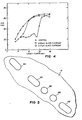
- Figure 4 shows CNR versus laser power curves for a control and the ceramic overcoated recording elements of Examples 1 and 2 infra.
- Figure 5 is a drawing of a scanning electon micrograph of the pits formed in
- Figure 1 shows apparatus for recording information on a recording element 16 and for playing back information therefrom.
- Recording element 16 comprises, as shown in Figure 2, an overcoat layer 41, an amorphous optical recording layer of a dye and a binder 42, reflecting layer 43, surface smoothing layer 44 and substrate 45.
- the intensity of a diode recording beam 10 is modulated in accordance with information to be recorded on recording element 16.
- the modulated laser beam is collected by a lens 14 and collimated by a lens 18 and is directed by means of mirror elements 20, 23 and 24 to a high numerical aperture lens 26 which focuses the modulated laser beam to a recording spot 28 on the recording element 16.
- the recording element 16 is spun at a constant rate, e.g., 1800 rotations per minute (rpm). As a result, a track of information 30 is recorded on the optical recording layer 42 and recording element 16 resulting in an information bearing recording element.
- the recording spot 28 is caused (by means not shown) to scan radially inward across the recording element 16, thereby causing information deformations to be recorded along a spiral track that extends from an outer radius R to an inner radius R i .
- the sizes and spacings of the recorded information marks vary in accordance with the information content of the recording laser drive signal, as well as with radial position on the recording element 16.
- the optical recording layer deforms to form pits surrounded by a sharply defined ridge.
- the ceramic overcoat forms a dome-like structure over the pit.
- Figure 3 is a cross section of recording element 16 after information has been recorded showing a pit 46 and the associated dome 47.
- “sharply defined ridge” is meant that the ridge and hole/depression have noticeable boundaries and that, as measured in the plane of the undeformed outer surface of the layer and in the direction of relative motion, if any, between the recording beam and the layer, the width of the ridge is less than or equal to the breadth of the hole/depression. This includes the case where the ridge itself is not noticeable but the bole/depression is sharply defined.
- the now information bearing record element 16 is spun at the same rate as it was spun during the recording process.
- a laser beam 22 from a readout laser is expanded in diameter by means of lenses 34 and 36.
- the optical path of the readout laser beam is folded by a beam splitter 21 and mirrors 23 and 24 so that the readout laser beam is focused to a playback spot on the recording element 16 by the high numerical aperture lens 26.
- the recording disk 16 is assumed to be of the reflective type so that the radiation forming the playback spot is reflected back through the high numerical aperture lens 26 after interacting with the information marks recorded on the optical element 16.
- a lens 38 directs reflected laser radiation -which has been diverted by the prism beamsplitter onto a detector 40 which produces an electrical playback signal in response to temporal variations in the irradiance of the reflected laser radiation falling on the detector.
- Useful ceramic overcoat materials are transparent at the read and write laser wavelength(s). Such overcoats should also have
- the overcoat material should be as stable as possible.
- Useful ceramic materials include aluminum oxide, silicon monoxide SiO, Al 2 O 3 , silicon dioxide Si0 2 , silica glass such as Schott-Glass. (available from Schott Glass Company), quartz and magnesium fluoride (MgF 2 ).
- Useful recording layers are the subject of U.S. Patent 4,380,769.
- the layers are amorphous dye-binder layers having an absorption factor greater than 20.
- the "absorption factor" of the amorphous material is defined as the product of the weight fraction of dye included in the amorphous material and the molar extinction coefficient of the dye at the wavelength of the recording beam of choice, divided by the molecular weight of the dye (MW), and having the units of liter per gm-cm.
- optical recording layer 42 preferably should have a very high optical density, i.e., an absorption factor of 20 or greater at the wavelength of the recording beam of choice, in order to be able to absorb sufficient energy from the recording beam to undergo proper thermal deformation.
- absorption factor is thickness-independent, while for a given dye-binder composition optical density is thickness-dependent. However, if the composition has an absorption factor greater than 20, even thin layers have a high density.
- the layer 42 has a glass transition temperature significantly higher than room temperature and lower than the temperature which is imparted during recording to a point on the layer by the recording beam of choice. Otherwise, the layer 42 is not able to retain the thermal deformation pattern after recording or is not capable of being recorded upon at all.
- a useful range of glass transition temperatures for layer 42 is preferably between about 40°C and about 150 s C, although higher and lower glass transition temperature materials are also useful.
- the support for the element is either reflective or transparent.
- both sides of the support are optionally reflective and an optical recording layer, along with its associated ceramaic overcoat layer, is coated on both sides of the support.
- the support itself is any of a wide variety of materials including glass, a self-supporting plastic such as poly(ethylene terepbtbalate), cellulose acetate, poly(methyl methacrylate), poly(vinyl chloride) and polystyrene, or a metal such as an aluminum sheet. It is desirable that the support have a relatively high melting point in order to avoid deformation of the support during recording.
- the support is desirably very smooth to minimize noise and dropouts in the recording-playback process.
- the support is coated with a smoothing layer prior to the coating of the reflective surface and the other layers of the optical recording element described herein.
- the composition which is used for the smoothing layer is preferably a low-viscosity, polymerizable fluid which is coated on the surface of the support. Following coating, polymerization of the fluid produces a surface on the support which appears smooth under microscopic examination. The support is then made reflective by vacuum metalization of the smooth surface such as by evaporating aluminum onto the smoothed surface of the support.
- An especially useful polymerizable fluid comprises photopolymerizable monomers.
- the monomers or mixtures of monomers are low-viscosity fluids in the absence of a solvent.
- Useful polymerizable fluid compositions are described in U.S. Patent 4,092,173 and U.S. Patent 4,171,979.
- the thickness of the optical recording layer 42 is preferably less then 0.45um. While high-absorption-factor layers of conventional thickness, i.e., 1-10um or greater, produce excellent recordings which are readable with a nonabsorbed read beam, exceptionally thin layers provide further improvements in carrier-to-noise ratio: For example, for a given material, recorded information played back from a layer with a thickness less then 0.45 ⁇ m usually has a carrier-to-noise ratio which is as many as 3 decibels greater than the playback from a 2 ⁇ m layer. In particularly preferred embodiments of the invention, layer 42 is less than 0.35 ⁇ m thick.
- the selected dye must be compatible with the binder.
- compatible is meant that the dye is capable of being mixed with the binder in sufficient concentration to provide the required absorption factor without crystallizing after the layer is dried.
- Layer 42 must be amorphous.
- the mixture generally comprises 1 part binder or mixture of binders by weight and 1 part dye or mixture of dyes by weight, but in some cases it is desirable to increase or decrease the proportion of binder in the mixture. In some cases, it is also useful to include a plasticizer in the mixture to achieve the desired deformation capabilities.
- the amorphous material is soluble in an organic solvent such as cyclohexanone, acetone, benzene or xylene.
- Useful binders are, for example, cellulose acetate butyrates, cellulose nitrate, polystyrenes, polysulfooamfdes, polycarbonates, cellulose nitrate, hydroabietyl alcohol (sold by the Hercules Chemical Co. as Abitol" AUK 257), poly(ethyl methacrylate), poly(vinyl butyral) and combinations and derivatives thereof.
- the preferred binder is a material comprising a mixture of non-polymeric compounds.
- the mixture is a) amorphous, b) solid at about 20°C, and c) comprises at least two different compounds each having at least two linking components joining one multivalent organic nucleus with at least two organic nuclei wherein at least one of the multivalent organic nuclei is a multicyclic or aromatic nucleus. Examples of such binders are presented in Table I.
- Such binders are the subject of U.S. Patent 4,499,165.
- the dye is chosen for its compatibility with the binder of choice, as discussed above, and for high absorptivity at the wavelength of the recording beam of choice. Innumerable dyes are available. Many such dyes are disclosed in U.S. patents 4,415,621 and 4,380,769 and Research Disclosure, Item 21638, April 1982, page 117, published by Industrial Opportunities, Ltd. 13-14 Homewell, Havent, Hampshire, England.
- Especially useful dyes include the metal dithiene dyes of the aforementioned Research Disclosure. Examples of such dyes are presented in Table II.
- Another group of preferred dyes are oxoindolizium dyes. Examples of such dyes are present in Table III.
- Laser write sensitivity of the overcoated recording elements 16 of the invention, compared to an unovercoated control, was determined by determining the laser power needed in each instance to write, i.e., form the proper pits to achieve the CNR obtained with the unovercoated control.
- Laser read/write performance of uncoated and ceramic overcoated optical recording layer 42 was determined by measuring carrier-to-noise ratio and bit error rate 'to determine the linearity of a recording.
- recordings and readback were carried out on the following basic optical recording element.
- the element was used as a control without a ceramic overcoat and as an example of the invention when overcoated with a ceramic material at a thickness less than 0.05pm.
- the overcoating was carried out by vacuum deposition.
- a 300-mm-diameter circular glass substrate was spin-coated with a surface-smoothing composition by flooding the glass substrate with the smoothing composition at low rpm (about 80-100 rpm) and then leveling the coating by advancing the speed to about 500 rpm.
- the surface-smoothing composition comprised: The coated and dried surface-smoothing composition was cured by irradiating with a 3000-watt pulsed xenon arc lamp at 18 inches for 4 minutes.
- the thus smoothed surface of the substrate was then coated with a 0.05 ⁇ m thick reflecting layer of aluminum by vapor deposition.
- a coating composition comprising a 1:1 mixture of a dye, or a mixture of dyes, and a binder dissolved in bromobenzene were prepared.
- the coating composition was spin coated on the reflecting layer at a low rpm and then leveled at about 800 rpm.
- the recording elements were ready for use as a control or overcoated to form an element of this invention.
- Overcoating of the element was carried out by vacuum deposition.
- Recordings were carried out using a 830 nm diode laser with the recording element 16 revolving at 1800 rpm. A carrier signal of 8.8 MHz was recorded. To determine carrier-to-noise ratio, the record bearing element was played back while being spun at the recording spin rate. The readout was carried out with a He-Ne laser.
- Example 1 0.01 ⁇ m Glass Overcoat
- Optical Recording Element No. 1 was used in this example.
- the carrier-to-noise ratio in decibels was determined for a control recording element without an overcoat and with 0.01 ⁇ m Schott-Glass * overcoat.
- the carrier-to-noise ratio was determined by recording at a series of laser powers and measuring CNR at each power level. Those results are shown in the curves of Figure 4. Those curves show that between laser powers of about 12 to 16 mW excellent carrier-to-noise ratios in excess of 60 are achieved for both the control and the overcoated sample.
- Figure 4 also shows that when readback is obtained through the use of a laser that is absorbed by the recording medium, the laser power which will accomplish the reading without damaging the recorded information, is more easily defined. That is the curve of CNR versus the laser power of Figure 4 shows that the 0.01 ⁇ m glass overcoated recording element has a sharper slope between about 6 and 8 mW than that of the control. This means that one is better able to choose a read-back power along the slope of the curve which is less likely to cause damage to the recorded information compared to the control.
- the types are FM encoded and digital.
- Digital data are first coded according to various types of codes available, such as Miller code or (2, 7) code. These coded data signals control the amount of time the pulsed recording diode laser is on and off according to the data pattern. The laser on and off times then determine the laser recorded pit length and pit to pit spacing. So, during digital recording, pits of various lengths are formed. The length of pit must vary linearly with laser on time. For example, if a laser is on for a time t and the recorded pit length is t, then pit length should be nl for a laser on time of nt.
- Figure 5 is a reproduction of a scanning electron photomicrograph which shows the linearity of the recordings made on the 0.01 ⁇ glass overcoated recording element.
- Pit 48 for which the recording laser pulse length was 0.200usec. at 450 rpm is exactly 0.5 times the length of pits 49 which were recorded with 0.400 ⁇ sec. pulses.
- bit error rate was determined.
- the bit error rate was determined with a Schlumberger 721 Telemetry bit error rate detector and MFM encoding. This measurement resulted in a determination that the 0.01 ⁇ m glass overcoat exhibited four bit errors in 14761 sixteen bit words. This bit error rate was the same for the control. Thus, the glass overcoat had no detrimental effect on the bit error rate in digital recordings. This bit error rate data is also evidence that the recordings were linear as described hereinbefore.
- Example 2 0.05 ⁇ m Glass Overcoat
- Optical Recording Element No. 1 was used in this example. Recording (laser writing) and playback (laser read) was conducted as in Example 1. Playback showed that the 0.05um Scbott-Glass overcoated sample provided high quality recordings with the carrier-to-noise ratio greater than 60 decibels in the laser power range of 12-16 mW. This result is also shown in Figure 4. This result shows that a 0.05pm overcoat does not have a significant deleterious effect on laser write sensitivity. Again, it can be seen from Figure 4 that the sharp slope of the CNR versus laser power curve for the 0.05 ⁇ m Schott-Glass overcoated sample is sharper than that of the control. Thus, one is able to choose a laser which is absorbed by the recorded information for read-back which falls along the sharp slope and thereby runs less risk of damaging the recorded information than in the case of the control.
- Example 1 Recording Element No. 1 was used in this example with 0.005pm MgF 2 overcoat. The effect of the MgF 2 overcoat on carrier-to-noise ratio was determined as in Example 1. Recording and playback were carried out on a MgF 2 overcoated basic recording element described above. The CNR results show essentially no loss in laser write sensitivity and laser read performance compared to the control of Example 1.
- Comparative Examples 4-5 show the adverse effect on recording linearity when overcoats thicker than 0.05pm are used.
- Example 4 A 0.1 ⁇ m Glass Overcoat
- Example 5 A 0.3 ⁇ m Glass Overcoat
Abstract
Description
- This invention relates to recording elements having overcoated amorphous optical recording layers of a dye and a binder.
- Recording elements in which information is recorded by thermally deforming an optical recording layer of a dye and a binder are known. Such elements are useful in rapidly recording large amounts of digital information in a small area. These elements are also useful in recording video information.
- Recording on an optical recording element is accomplished by a beam of high energy-density radiation such as a laser beam. The laser beam is focused onto the surface-of the optical recording layer of the element. The recording layer absorbs energy from the laser so that a small portion of the layer is deformed. The deformation may be in the form of pits, holes or other changes in the material. This technique of optical recording on a heat-deformable recording layer is usually referred to in the optical recording art as "ablative recording".
- Generally, there is continuous relative motion between the laser beam and the layer so that as the laser is pulse modulated, discrete deformations of varying sizes are created in the layer. The sizes and spacing of these deformations constitute the encoded information.
- Especially useful optical recording layers are disclosed in U.S. Patent 4,380,769. The layers are an amorphous mixture of a dye and a binder. It is desirable to protect such layers during laser writing and reading processes. U.S. Patent 4,388,400 discloses the ceramic protective layers coated over metal recording layers. The thickness of the gro- tective layers are in the range of 0.01µm to Sum. However, ceramic protective layers having thicknesses over most of the upper part of this thickness range have a deleterious effect upon the laser write sensitivity, upon the carrier-to-noise ratio (CNR) and recording linearity (variation of length of recorded deformations with laser on time) of optical recording layers of the type disclosed in U.S. Patent 4,380,769.
- It is an object of this invention to provide recording elements having an amorphous recording layer of a dye and a binder overcoated with a protective layer which eliminates or minimizes the deleterious effects.of prior art overcoated optical recording layers.
- This objective has been achieved with a recording element comprising an amorphous optical recording layer of a dye and a binder characterized in that a ceramic overcoat having a thickness up to 0.05pm is coated over the recording layer. The range of thickness of the thin ceramic overcoat used in this invention is only 1.0 percent of the 5µm wide range for ceramic overcoats disclosed in the prior art.
- The recording elements of this invention having thin ceramic overcoats up to 0.05µm suffer essentially no loss in recording sensitivity. Recorded information on the elements have excellent carrier-to-noise ratio (CNR) and linearity. Moreover, diode lasers can be used to record and readback recorded information.
- Also, the invention provides a recording element useful for high-quality, high-information density recordings. "High-quality recording" as used herein is defined as a recording which, when read back, has a carrier-to-noise ratio at a 30 KHZ slot- noise bandwidth greater than or equal to 40 decibels and few imperfections or dropouts.
- Figure 1 shows a schematic apparatus for recording and reading back information on the recording elements of the invention. Figures 2 and 3 show a cross section of a recording element of the invention before and after recording respectively. Figure 4 shows CNR versus laser power curves for a control and the ceramic overcoated recording elements of Examples 1 and 2 infra. Figure 5 is a drawing of a scanning electon micrograph of the pits formed in
- Figure 1 shows apparatus for recording information on a
recording element 16 and for playing back information therefrom.Recording element 16 comprises, as shown in Figure 2, anovercoat layer 41, an amorphous optical recording layer of a dye and abinder 42, reflectinglayer 43,surface smoothing layer 44 andsubstrate 45. In response to a drive signal, the intensity of adiode recording beam 10 is modulated in accordance with information to be recorded onrecording element 16. The modulated laser beam is collected by alens 14 and collimated by alens 18 and is directed by means ofmirror elements numerical aperture lens 26 which focuses the modulated laser beam to arecording spot 28 on therecording element 16. - During recording, the
recording element 16 is spun at a constant rate, e.g., 1800 rotations per minute (rpm). As a result, a track ofinformation 30 is recorded on theoptical recording layer 42 and recordingelement 16 resulting in an information bearing recording element. As recording continues, therecording spot 28 is caused (by means not shown) to scan radially inward across therecording element 16, thereby causing information deformations to be recorded along a spiral track that extends from an outer radius R to an inner radius Ri. The sizes and spacings of the recorded information marks vary in accordance with the information content of the recording laser drive signal, as well as with radial position on therecording element 16. - When the recordings are carried out on the ceramic overcoated optical elements of the present invention, the optical recording layer deforms to form pits surrounded by a sharply defined ridge. In addition, the ceramic overcoat forms a dome-like structure over the pit. Figure 3 is a cross section of
recording element 16 after information has been recorded showing a pit 46 and the associateddome 47. By "sharply defined ridge" is meant that the ridge and hole/depression have noticeable boundaries and that, as measured in the plane of the undeformed outer surface of the layer and in the direction of relative motion, if any, between the recording beam and the layer, the width of the ridge is less than or equal to the breadth of the hole/depression. This includes the case where the ridge itself is not noticeable but the bole/depression is sharply defined. - During the readback process, the now information bearing
record element 16 is spun at the same rate as it was spun during the recording process. Alaser beam 22 from a readout laser is expanded in diameter by means oflenses beam splitter 21 andmirrors 23 and 24 so that the readout laser beam is focused to a playback spot on therecording element 16 by the highnumerical aperture lens 26. Therecording disk 16 is assumed to be of the reflective type so that the radiation forming the playback spot is reflected back through the highnumerical aperture lens 26 after interacting with the information marks recorded on theoptical element 16. (In the case of a transmissive optical element, the playback optical system would be arranged so that the playback spot would pass through the optical disk in order to interact with recorded information marks.) Alens 38 directs reflected laser radiation -which has been diverted by the prism beamsplitter onto adetector 40 which produces an electrical playback signal in response to temporal variations in the irradiance of the reflected laser radiation falling on the detector. - Useful ceramic overcoat materials are transparent at the read and write laser wavelength(s). Such overcoats should also have
- 1) low thermal diffusivity to avoid heat loss to the overcoat during recording;
- 2) low adhesion to the optical recording layer;
- 3) high viscosity under high temperature to avoid excessive flow during pit formation; and
- 4) be coatable in a continuous, homogenous film on the optical recording layer.
- Desirably, the overcoat material should be as stable as possible. Useful ceramic materials include aluminum oxide, silicon monoxide SiO, Al2O3, silicon dioxide Si02, silica glass such as Schott-Glass. (available from Schott Glass Company), quartz and magnesium fluoride (MgF2).
- Useful recording layers are the subject of U.S. Patent 4,380,769. The layers are amorphous dye-binder layers having an absorption factor greater than 20. The "absorption factor" of the amorphous material is defined as the product of the weight fraction of dye included in the amorphous material and the molar extinction coefficient of the dye at the wavelength of the recording beam of choice, divided by the molecular weight of the dye (MW), and having the units of liter per gm-cm.
- Thus,
optical recording layer 42 preferably should have a very high optical density, i.e., an absorption factor of 20 or greater at the wavelength of the recording beam of choice, in order to be able to absorb sufficient energy from the recording beam to undergo proper thermal deformation. (It will be readily appreciated that absorption factor is thickness-independent, while for a given dye-binder composition optical density is thickness-dependent. However, if the composition has an absorption factor greater than 20, even thin layers have a high density.) Thelayer 42 has a glass transition temperature significantly higher than room temperature and lower than the temperature which is imparted during recording to a point on the layer by the recording beam of choice. Otherwise, thelayer 42 is not able to retain the thermal deformation pattern after recording or is not capable of being recorded upon at all. A useful range of glass transition temperatures forlayer 42 is preferably between about 40°C and about 150sC, although higher and lower glass transition temperature materials are also useful. - Depending upon the desired mode of reading the recording element of the present invention, the support for the element is either reflective or transparent. In the case of a reflective support, both sides of the support are optionally reflective and an optical recording layer, along with its associated ceramaic overcoat layer, is coated on both sides of the support. The support itself is any of a wide variety of materials including glass, a self-supporting plastic such as poly(ethylene terepbtbalate), cellulose acetate, poly(methyl methacrylate), poly(vinyl chloride) and polystyrene, or a metal such as an aluminum sheet. It is desirable that the support have a relatively high melting point in order to avoid deformation of the support during recording. The support is desirably very smooth to minimize noise and dropouts in the recording-playback process. In certain preferred embodiments, the support is coated with a smoothing layer prior to the coating of the reflective surface and the other layers of the optical recording element described herein.
- The composition which is used for the smoothing layer is preferably a low-viscosity, polymerizable fluid which is coated on the surface of the support. Following coating, polymerization of the fluid produces a surface on the support which appears smooth under microscopic examination. The support is then made reflective by vacuum metalization of the smooth surface such as by evaporating aluminum onto the smoothed surface of the support. An especially useful polymerizable fluid comprises photopolymerizable monomers. Preferably, the monomers or mixtures of monomers are low-viscosity fluids in the absence of a solvent. Useful polymerizable fluid compositions are described in U.S. Patent 4,092,173 and U.S. Patent 4,171,979.
- The thickness of the
optical recording layer 42 is preferably less then 0.45um. While high-absorption-factor layers of conventional thickness, i.e., 1-10um or greater, produce excellent recordings which are readable with a nonabsorbed read beam, exceptionally thin layers provide further improvements in carrier-to-noise ratio: For example, for a given material, recorded information played back from a layer with a thickness less then 0.45µm usually has a carrier-to-noise ratio which is as many as 3 decibels greater than the playback from a 2µm layer. In particularly preferred embodiments of the invention,layer 42 is less than 0.35µm thick. - The selected dye must be compatible with the binder. By "compatible" is meant that the dye is capable of being mixed with the binder in sufficient concentration to provide the required absorption factor without crystallizing after the layer is dried.
Layer 42 must be amorphous. The mixture generally comprises 1 part binder or mixture of binders by weight and 1 part dye or mixture of dyes by weight, but in some cases it is desirable to increase or decrease the proportion of binder in the mixture. In some cases, it is also useful to include a plasticizer in the mixture to achieve the desired deformation capabilities. In preferred embodiments, the amorphous material is soluble in an organic solvent such as cyclohexanone, acetone, benzene or xylene. - Useful binders are, for example, cellulose acetate butyrates, cellulose nitrate, polystyrenes, polysulfooamfdes, polycarbonates, cellulose nitrate, hydroabietyl alcohol (sold by the Hercules Chemical Co. as Abitol" AUK 257), poly(ethyl methacrylate), poly(vinyl butyral) and combinations and derivatives thereof. The preferred binder is a material comprising a mixture of non-polymeric compounds. The mixture is a) amorphous, b) solid at about 20°C, and c) comprises at least two different compounds each having at least two linking components joining one multivalent organic nucleus with at least two organic nuclei wherein at least one of the multivalent organic nuclei is a multicyclic or aromatic nucleus. Examples of such binders are presented in Table I.


- Such binders are the subject of U.S. Patent 4,499,165.
- The dye is chosen for its compatibility with the binder of choice, as discussed above, and for high absorptivity at the wavelength of the recording beam of choice. Innumerable dyes are available. Many such dyes are disclosed in U.S. patents 4,415,621 and 4,380,769 and Research Disclosure, Item 21638, April 1982, page 117, published by Industrial Opportunities, Ltd. 13-14 Homewell, Havent, Hampshire, England.
- Especially useful dyes include the metal dithiene dyes of the aforementioned Research Disclosure. Examples of such dyes are presented in Table II.

- Another group of preferred dyes are oxoindolizium dyes. Examples of such dyes are present in Table III.

- The following examples are presented to illustrate the effect of ceramic overcoats on the laser write sensitivity and on the laser read/write performance of recording elements as reflected in carrier-to-noise ratios and linearity of recording from bit error rate measurements.
- Laser write sensitivity of the
overcoated recording elements 16 of the invention, compared to an unovercoated control, was determined by determining the laser power needed in each instance to write, i.e., form the proper pits to achieve the CNR obtained with the unovercoated control. - Laser read/write performance of uncoated and ceramic overcoated
optical recording layer 42 was determined by measuring carrier-to-noise ratio and bit error rate 'to determine the linearity of a recording. To carry out the foregoing measurements, recordings and readback were carried out on the following basic optical recording element. The element was used as a control without a ceramic overcoat and as an example of the invention when overcoated with a ceramic material at a thickness less than 0.05pm. The overcoating was carried out by vacuum deposition. - Three different recording elements were prepared as follows. A 300-mm-diameter circular glass substrate was spin-coated with a surface-smoothing composition by flooding the glass substrate with the smoothing composition at low rpm (about 80-100 rpm) and then leveling the coating by advancing the speed to about 500 rpm. The surface-smoothing composition comprised:

- The thus smoothed surface of the substrate was then coated with a 0.05µm thick reflecting layer of aluminum by vapor deposition.
- A coating composition comprising a 1:1 mixture of a dye, or a mixture of dyes, and a binder dissolved in bromobenzene were prepared. The coating composition was spin coated on the reflecting layer at a low rpm and then leveled at about 800 rpm.
- Using the above procedure, two different recording elements were prepared which were identical except for the optical recording layers. The layers bad the following composition:
- 1 part of a 1:1 mixture of dyes 2 and 3 from Table II plus 1 part of binder 1 from Table 1
- 1 part dye 3 from Table III plus 1 part of binder 3 from Table I.
- After drying, the recording elements were ready for use as a control or overcoated to form an element of this invention. Overcoating of the element was carried out by vacuum deposition.
- Recordings were carried out using a 830 nm diode laser with the
recording element 16 revolving at 1800 rpm. A carrier signal of 8.8 MHz was recorded. To determine carrier-to-noise ratio, the record bearing element was played back while being spun at the recording spin rate. The readout was carried out with a He-Ne laser. - Optical Recording Element No. 1 was used in this example. The carrier-to-noise ratio in decibels was determined for a control recording element without an overcoat and with 0.01µm Schott-Glass* overcoat. The carrier-to-noise ratio was determined by recording at a series of laser powers and measuring CNR at each power level. Those results are shown in the curves of Figure 4. Those curves show that between laser powers of about 12 to 16 mW excellent carrier-to-noise ratios in excess of 60 are achieved for both the control and the overcoated sample. While the carrier-to-noise ratio of the control is slightly higher than that of the overcoated element, the difference is only about 4-5 decibels indicating essentially no effect on the carrier-to-noise ratio by the 0.01µm Schott-Glass overcoat. In both cases high quality recordings are achieved. These measurements also show that the sensitivity of the control and the 0.01 Schott-Glass overcoated element are substantially equivalent in that a high CNR was achieved with both elements using the same amount of laser power.
- Figure 4 also shows that when readback is obtained through the use of a laser that is absorbed by the recording medium, the laser power which will accomplish the reading without damaging the recorded information, is more easily defined. That is the curve of CNR versus the laser power of Figure 4 shows that the 0.01µm glass overcoated recording element has a sharper slope between about 6 and 8 mW than that of the control. This means that one is better able to choose a read-back power along the slope of the curve which is less likely to cause damage to the recorded information compared to the control.
- Basically there are two types of information which can be stored on recording elements of the type described herein. The types are FM encoded and digital. Digital data are first coded according to various types of codes available, such as Miller code or (2, 7) code. These coded data signals control the amount of time the pulsed recording diode laser is on and off according to the data pattern. The laser on and off times then determine the laser recorded pit length and pit to pit spacing. So, during digital recording, pits of various lengths are formed. The length of pit must vary linearly with laser on time. For example, if a laser is on for a time t and the recorded pit length is t, then pit length should be nℓ for a laser on time of nt. Figure 5 is a reproduction of a scanning electron photomicrograph which shows the linearity of the recordings made on the 0.01µµ glass overcoated recording element.
Pit 48 for which the recording laser pulse length was 0.200usec. at 450 rpm is exactly 0.5 times the length ofpits 49 which were recorded with 0.400µsec. pulses. - This linear behavior is obtained because ceramic overcoats up to 0.05pm thick do not impede the flow of the
heated recording layer 42 during pit formstion. The overcoat forms adome 47 over the pit, allowing the recording medium to flow into rims. - To determine the effect of the 0.01µm glass overcoat on bit error rate, and therefore the utility of ceramic overcoated optical recording elements for pulse modulated encoded digital recordings, the bit error rate was determined. The bit error rate was determined with a Schlumberger 721 Telemetry bit error rate detector and MFM encoding. This measurement resulted in a determination that the 0.01µm glass overcoat exhibited four bit errors in 14761 sixteen bit words. This bit error rate was the same for the control. Thus, the glass overcoat had no detrimental effect on the bit error rate in digital recordings. This bit error rate data is also evidence that the recordings were linear as described hereinbefore.
- Optical Recording Element No. 1 was used in this example. Recording (laser writing) and playback (laser read) was conducted as in Example 1. Playback showed that the 0.05um Scbott-Glass overcoated sample provided high quality recordings with the carrier-to-noise ratio greater than 60 decibels in the laser power range of 12-16 mW. This result is also shown in Figure 4. This result shows that a 0.05pm overcoat does not have a significant deleterious effect on laser write sensitivity. Again, it can be seen from Figure 4 that the sharp slope of the CNR versus laser power curve for the 0.05µm Schott-Glass overcoated sample is sharper than that of the control. Thus, one is able to choose a laser which is absorbed by the recorded information for read-back which falls along the sharp slope and thereby runs less risk of damaging the recorded information than in the case of the control.
- Recording Element No. 1 was used in this example with 0.005pm MgF2 overcoat. The effect of the MgF2 overcoat on carrier-to-noise ratio was determined as in Example 1. Recording and playback were carried out on a MgF2 overcoated basic recording element described above. The CNR results show essentially no loss in laser write sensitivity and laser read performance compared to the control of Example 1.
- Comparative Examples 4-5 show the adverse effect on recording linearity when overcoats thicker than 0.05pm are used.
- Recording Element No. 2 was used in this example with a O.lpm Schott-Glass overcoat. The maximum carrier-to-noise ratio obtainable was less than 40 decibels at 1800 rpm with 8.8 MHz frequency on a glass support at a radius of 100 mm with 16 mW diode laser power. Using the standard digital recording conditions (5 Mb/sec, Miller Coded data, at disk speed 450 rpm, R-100 mm) the O.lpm Schott-Glass overcoated element could not be read back successfully. Bit error ratio could not be determined because of signal distortions and nonlinearities in laser recording caused by the O.lpm Schott-Glass overcoat.
- Recording Element No. 2 was used in this example with a 0.3µm Schott-Glassovercoat. The maximum carrier-to-noise ratio was measured as 50 decibels at 1800 rpm, 8.8 MHz frequency on a glass substrate disk at a radius of 100 mm with 16 mW diode laser power. Under usual digital recording conditions (5 Mb/sec. Miller coded data, disk speed 450 rpm, radius 100 mm) bit error ratio measurements could not be performed because of nonlinearity in laser recordings with a 0.3um overcoat.
Claims (8)
Applications Claiming Priority (2)
| Application Number | Priority Date | Filing Date | Title |
|---|---|---|---|
| US06/600,643 US4538159A (en) | 1984-04-16 | 1984-04-16 | Ceramic overcoated optical recording element |
| US600643 | 1984-04-16 |
Publications (2)
| Publication Number | Publication Date |
|---|---|
| EP0161809A1 true EP0161809A1 (en) | 1985-11-21 |
| EP0161809B1 EP0161809B1 (en) | 1989-03-15 |
Family
ID=24404467
Family Applications (1)
| Application Number | Title | Priority Date | Filing Date |
|---|---|---|---|
| EP85302603A Expired EP0161809B1 (en) | 1984-04-16 | 1985-04-15 | Overcoated recording elements having amorphous dye and binder optical recording layers |
Country Status (5)
| Country | Link |
|---|---|
| US (1) | US4538159A (en) |
| EP (1) | EP0161809B1 (en) |
| JP (1) | JPS60253036A (en) |
| CA (1) | CA1229915A (en) |
| DE (1) | DE3568887D1 (en) |
Cited By (2)
| Publication number | Priority date | Publication date | Assignee | Title |
|---|---|---|---|---|
| EP0392355A2 (en) * | 1989-04-11 | 1990-10-17 | BASF Aktiengesellschaft | Optical-recording medium |
| EP0451718A1 (en) * | 1990-04-07 | 1991-10-16 | MITSUI TOATSU CHEMICALS, Inc. | Compact disk-write once type optical recording media |
Families Citing this family (10)
| Publication number | Priority date | Publication date | Assignee | Title |
|---|---|---|---|---|
| US4757472A (en) * | 1986-12-31 | 1988-07-12 | Tecon Memory, Inc. | Electrophotographic optical memory system |
| JPH0798421B2 (en) * | 1987-06-09 | 1995-10-25 | 富士写真フイルム株式会社 | Optical information recording medium |
| DE68923777T2 (en) * | 1988-12-29 | 1996-05-02 | Sony Corp | Optical recording medium. |
| JP3130930B2 (en) * | 1990-09-24 | 2001-01-31 | イーストマン・コダック・カンパニー | Method for overwriting information on optical disk media |
| US5343458A (en) * | 1992-09-15 | 1994-08-30 | Samsung Electronics Co., Ltd. | Method of storing digital video, audio and control information on an an optical storage medium |
| DE69319883T2 (en) * | 1992-09-15 | 1998-12-24 | Samsung Electronics Co Ltd | MULTIPLEX SYSTEM FOR VIDEO |
| US5363200A (en) * | 1992-09-15 | 1994-11-08 | Samsung Electronics Co., Ltd. | Buffering method and system for resonant scanner used to read and write data with respect to a storage medium |
| US5321684A (en) * | 1992-09-15 | 1994-06-14 | Sri International | Bidirectional sinusoidal scanning system |
| JPH09306030A (en) * | 1996-05-10 | 1997-11-28 | Sony Corp | Recording medium |
| US6191384B1 (en) | 1998-05-05 | 2001-02-20 | Tapematic S.P.A. | Apparatus for trimming dye coated on a recordable disc substrate and related method |
Citations (5)
| Publication number | Priority date | Publication date | Assignee | Title |
|---|---|---|---|---|
| US4069487A (en) * | 1974-12-26 | 1978-01-17 | Canon Kabushiki Kaisha | Recording member and process for recording |
| US4242689A (en) * | 1977-09-19 | 1980-12-30 | Rca Corporation | Ablative optical recording medium |
| DE3139718A1 (en) * | 1980-10-06 | 1982-05-19 | Fuji Photo Film Co., Ltd., Minami-Ashigara, Kanagawa | HEAT RECORDING MATERIAL |
| US4380769A (en) * | 1977-12-19 | 1983-04-19 | Eastman Kodak Company | Element for recording by thermal deformation |
| US4446223A (en) * | 1982-06-24 | 1984-05-01 | Eastman Kodak Company | Recording and information record elements comprising oxoindolizine and oxoindolizinium dyes |
Family Cites Families (6)
| Publication number | Priority date | Publication date | Assignee | Title |
|---|---|---|---|---|
| FR2355337A1 (en) * | 1976-06-18 | 1978-01-13 | Thomson Brandt | Optical read-write system for disc memories - has disc sandwiched between covers to prevent errors due to dust particles or surface scratches (NL 20.12.77) |
| US4101907A (en) * | 1977-08-29 | 1978-07-18 | Rca Corporation | Overcoat structure for optical video disc |
| US4300143A (en) * | 1977-08-29 | 1981-11-10 | Rca Corporation | Thin protective overcoat layer for optical video disc |
| JPS5613534A (en) * | 1979-07-16 | 1981-02-09 | Toshiba Corp | Optical recording body and its manufacture |
| US4268840A (en) * | 1979-07-27 | 1981-05-19 | Xerox Corporation | Optical recording member |
| US4314262A (en) * | 1980-02-04 | 1982-02-02 | Xerox Corporation | Optical data recording medium |
-
1984
- 1984-04-16 US US06/600,643 patent/US4538159A/en not_active Expired - Fee Related
- 1984-08-03 CA CA000460305A patent/CA1229915A/en not_active Expired
-
1985
- 1985-04-15 JP JP60078641A patent/JPS60253036A/en active Pending
- 1985-04-15 DE DE8585302603T patent/DE3568887D1/en not_active Expired
- 1985-04-15 EP EP85302603A patent/EP0161809B1/en not_active Expired
Patent Citations (5)
| Publication number | Priority date | Publication date | Assignee | Title |
|---|---|---|---|---|
| US4069487A (en) * | 1974-12-26 | 1978-01-17 | Canon Kabushiki Kaisha | Recording member and process for recording |
| US4242689A (en) * | 1977-09-19 | 1980-12-30 | Rca Corporation | Ablative optical recording medium |
| US4380769A (en) * | 1977-12-19 | 1983-04-19 | Eastman Kodak Company | Element for recording by thermal deformation |
| DE3139718A1 (en) * | 1980-10-06 | 1982-05-19 | Fuji Photo Film Co., Ltd., Minami-Ashigara, Kanagawa | HEAT RECORDING MATERIAL |
| US4446223A (en) * | 1982-06-24 | 1984-05-01 | Eastman Kodak Company | Recording and information record elements comprising oxoindolizine and oxoindolizinium dyes |
Non-Patent Citations (2)
| Title |
|---|
| APPLIED PHYSICS LETTERS, vol. 38, no. 11, 1st June 1981, New York, USA; A.E. BELL et al. "Reversible optical recording in trilayer structures", pages 920-921 * |
| RESEARCH DISCLOSURE, no. 216, April 1982, Havant, Hampshire, GB; pages 117-118 * |
Cited By (3)
| Publication number | Priority date | Publication date | Assignee | Title |
|---|---|---|---|---|
| EP0392355A2 (en) * | 1989-04-11 | 1990-10-17 | BASF Aktiengesellschaft | Optical-recording medium |
| EP0392355A3 (en) * | 1989-04-11 | 1991-05-22 | BASF Aktiengesellschaft | Optical-recording medium |
| EP0451718A1 (en) * | 1990-04-07 | 1991-10-16 | MITSUI TOATSU CHEMICALS, Inc. | Compact disk-write once type optical recording media |
Also Published As
| Publication number | Publication date |
|---|---|
| EP0161809B1 (en) | 1989-03-15 |
| DE3568887D1 (en) | 1989-04-20 |
| CA1229915A (en) | 1987-12-01 |
| JPS60253036A (en) | 1985-12-13 |
| US4538159A (en) | 1985-08-27 |
Similar Documents
| Publication | Publication Date | Title |
|---|---|---|
| US4527173A (en) | Erasable, reusable optical recording element and method | |
| JPH0415112B2 (en) | ||
| JPH0613238B2 (en) | Optical information recording medium | |
| EP0161809B1 (en) | Overcoated recording elements having amorphous dye and binder optical recording layers | |
| EP0474311A1 (en) | Optical data recording medium, method for writing and reading data and apparatus for recording data | |
| US5283094A (en) | Optical recording medium | |
| EP0996123B1 (en) | Optical recording medium and optical recording method | |
| EP0193388B1 (en) | Optical recording and information elements | |
| JP2617523B2 (en) | Optical data storage element | |
| EP0204876A1 (en) | Optical data storage medium having a highly reflective organic information layer | |
| JP3543464B2 (en) | Optical recording medium and information recording method | |
| JP3649062B2 (en) | Optical recording medium and optical recording method | |
| JPH02232832A (en) | Information recording medium | |
| EP0237873B1 (en) | Optical recording medium | |
| JP3073266B2 (en) | Manufacturing method of optical recording medium | |
| JP3434524B2 (en) | Optical recording medium | |
| JP3141998B2 (en) | Information recording medium | |
| JPH05147356A (en) | Optical recording medium | |
| JPH0524360A (en) | Light recording medium | |
| Jones et al. | Organic Materials for Optical Data Storage | |
| JPH0251391B2 (en) | ||
| JPS6163939A (en) | Information storage device | |
| JPH0251392B2 (en) | ||
| JPS6137475A (en) | Optical recording element | |
| JPH0373385A (en) | Information recording medium |
Legal Events
| Date | Code | Title | Description |
|---|---|---|---|
| PUAI | Public reference made under article 153(3) epc to a published international application that has entered the european phase |
Free format text: ORIGINAL CODE: 0009012 |
|
| AK | Designated contracting states |
Designated state(s): DE FR GB NL |
|
| 17P | Request for examination filed |
Effective date: 19860421 |
|
| 17Q | First examination report despatched |
Effective date: 19880725 |
|
| GRAA | (expected) grant |
Free format text: ORIGINAL CODE: 0009210 |
|
| AK | Designated contracting states |
Kind code of ref document: B1 Designated state(s): DE FR GB NL |
|
| REF | Corresponds to: |
Ref document number: 3568887 Country of ref document: DE Date of ref document: 19890420 |
|
| ET | Fr: translation filed | ||
| PLBE | No opposition filed within time limit |
Free format text: ORIGINAL CODE: 0009261 |
|
| STAA | Information on the status of an ep patent application or granted ep patent |
Free format text: STATUS: NO OPPOSITION FILED WITHIN TIME LIMIT |
|
| 26N | No opposition filed | ||
| PGFP | Annual fee paid to national office [announced via postgrant information from national office to epo] |
Ref country code: GB Payment date: 19910315 Year of fee payment: 7 |
|
| PGFP | Annual fee paid to national office [announced via postgrant information from national office to epo] |
Ref country code: DE Payment date: 19910410 Year of fee payment: 7 |
|
| PGFP | Annual fee paid to national office [announced via postgrant information from national office to epo] |
Ref country code: FR Payment date: 19910415 Year of fee payment: 7 |
|
| PGFP | Annual fee paid to national office [announced via postgrant information from national office to epo] |
Ref country code: NL Payment date: 19910430 Year of fee payment: 7 |
|
| PG25 | Lapsed in a contracting state [announced via postgrant information from national office to epo] |
Ref country code: GB Effective date: 19920415 |
|
| PG25 | Lapsed in a contracting state [announced via postgrant information from national office to epo] |
Ref country code: NL Effective date: 19921101 |
|
| GBPC | Gb: european patent ceased through non-payment of renewal fee | ||
| NLV4 | Nl: lapsed or anulled due to non-payment of the annual fee | ||
| PG25 | Lapsed in a contracting state [announced via postgrant information from national office to epo] |
Ref country code: FR Effective date: 19921230 |
|
| PG25 | Lapsed in a contracting state [announced via postgrant information from national office to epo] |
Ref country code: DE Effective date: 19930101 |
|
| REG | Reference to a national code |
Ref country code: FR Ref legal event code: ST |