EP0158823A2 - Process and device for purifying exhaust gases - Google Patents
Process and device for purifying exhaust gases Download PDFInfo
- Publication number
- EP0158823A2 EP0158823A2 EP85102807A EP85102807A EP0158823A2 EP 0158823 A2 EP0158823 A2 EP 0158823A2 EP 85102807 A EP85102807 A EP 85102807A EP 85102807 A EP85102807 A EP 85102807A EP 0158823 A2 EP0158823 A2 EP 0158823A2
- Authority
- EP
- European Patent Office
- Prior art keywords
- discharge
- reactor
- electrode
- electrodes
- plasma
- Prior art date
- Legal status (The legal status is an assumption and is not a legal conclusion. Google has not performed a legal analysis and makes no representation as to the accuracy of the status listed.)
- Withdrawn
Links
Images
Classifications
-
- B—PERFORMING OPERATIONS; TRANSPORTING
- B01—PHYSICAL OR CHEMICAL PROCESSES OR APPARATUS IN GENERAL
- B01D—SEPARATION
- B01D53/00—Separation of gases or vapours; Recovering vapours of volatile solvents from gases; Chemical or biological purification of waste gases, e.g. engine exhaust gases, smoke, fumes, flue gases, aerosols
- B01D53/34—Chemical or biological purification of waste gases
- B01D53/46—Removing components of defined structure
- B01D53/60—Simultaneously removing sulfur oxides and nitrogen oxides
-
- B—PERFORMING OPERATIONS; TRANSPORTING
- B01—PHYSICAL OR CHEMICAL PROCESSES OR APPARATUS IN GENERAL
- B01D—SEPARATION
- B01D53/00—Separation of gases or vapours; Recovering vapours of volatile solvents from gases; Chemical or biological purification of waste gases, e.g. engine exhaust gases, smoke, fumes, flue gases, aerosols
- B01D53/32—Separation of gases or vapours; Recovering vapours of volatile solvents from gases; Chemical or biological purification of waste gases, e.g. engine exhaust gases, smoke, fumes, flue gases, aerosols by electrical effects other than those provided for in group B01D61/00
-
- B—PERFORMING OPERATIONS; TRANSPORTING
- B01—PHYSICAL OR CHEMICAL PROCESSES OR APPARATUS IN GENERAL
- B01D—SEPARATION
- B01D53/00—Separation of gases or vapours; Recovering vapours of volatile solvents from gases; Chemical or biological purification of waste gases, e.g. engine exhaust gases, smoke, fumes, flue gases, aerosols
- B01D53/34—Chemical or biological purification of waste gases
- B01D53/46—Removing components of defined structure
- B01D53/54—Nitrogen compounds
-
- B—PERFORMING OPERATIONS; TRANSPORTING
- B03—SEPARATION OF SOLID MATERIALS USING LIQUIDS OR USING PNEUMATIC TABLES OR JIGS; MAGNETIC OR ELECTROSTATIC SEPARATION OF SOLID MATERIALS FROM SOLID MATERIALS OR FLUIDS; SEPARATION BY HIGH-VOLTAGE ELECTRIC FIELDS
- B03C—MAGNETIC OR ELECTROSTATIC SEPARATION OF SOLID MATERIALS FROM SOLID MATERIALS OR FLUIDS; SEPARATION BY HIGH-VOLTAGE ELECTRIC FIELDS
- B03C3/00—Separating dispersed particles from gases or vapour, e.g. air, by electrostatic effect
- B03C3/34—Constructional details or accessories or operation thereof
- B03C3/38—Particle charging or ionising stations, e.g. using electric discharge, radioactive radiation or flames
-
- B—PERFORMING OPERATIONS; TRANSPORTING
- B03—SEPARATION OF SOLID MATERIALS USING LIQUIDS OR USING PNEUMATIC TABLES OR JIGS; MAGNETIC OR ELECTROSTATIC SEPARATION OF SOLID MATERIALS FROM SOLID MATERIALS OR FLUIDS; SEPARATION BY HIGH-VOLTAGE ELECTRIC FIELDS
- B03C—MAGNETIC OR ELECTROSTATIC SEPARATION OF SOLID MATERIALS FROM SOLID MATERIALS OR FLUIDS; SEPARATION BY HIGH-VOLTAGE ELECTRIC FIELDS
- B03C3/00—Separating dispersed particles from gases or vapour, e.g. air, by electrostatic effect
- B03C3/34—Constructional details or accessories or operation thereof
- B03C3/40—Electrode constructions
- B03C3/60—Use of special materials other than liquids
-
- Y—GENERAL TAGGING OF NEW TECHNOLOGICAL DEVELOPMENTS; GENERAL TAGGING OF CROSS-SECTIONAL TECHNOLOGIES SPANNING OVER SEVERAL SECTIONS OF THE IPC; TECHNICAL SUBJECTS COVERED BY FORMER USPC CROSS-REFERENCE ART COLLECTIONS [XRACs] AND DIGESTS
- Y02—TECHNOLOGIES OR APPLICATIONS FOR MITIGATION OR ADAPTATION AGAINST CLIMATE CHANGE
- Y02A—TECHNOLOGIES FOR ADAPTATION TO CLIMATE CHANGE
- Y02A50/00—TECHNOLOGIES FOR ADAPTATION TO CLIMATE CHANGE in human health protection, e.g. against extreme weather
- Y02A50/20—Air quality improvement or preservation, e.g. vehicle emission control or emission reduction by using catalytic converters
Definitions
- the invention relates to a method for cleaning exhaust gases according to the preamble of claim 1 and to an apparatus for performing the method.
- Such a method is suitable for cleaning NO x , S0 2 and dust-containing exhaust gases of all kinds, regardless of whether they come from an internal combustion engine or an incineration plant.
- the invention is therefore based on the object of demonstrating a method with which NO x , S0 2 and dust Exhaust gases of any kind can be cleaned very cheaply.
- the method according to the invention it is possible to chemically convert the proportions of NO x and SO 2 contained in the exhaust gas.
- NO in particular can be reduced and S0 2 -oxidized or both gases can be oxidized.
- the intermediates formed in this reaction for example H 2 SO 4 or HN0 3, can be condensed or converted into ammonium sulfate or ammonium nitrate by adding ammonia.
- Other additives with an oxidizing or reducing character are also possible.
- the dust contained in the exhaust gas is separated from the exhaust gas with the aid of the electrical field that is formed.
- a reactor which has two flat electrodes which are arranged parallel to one another at a defined distance.
- One of the two electrodes is coated on its side facing the second electrode with a dielectric material, preferably glass.
- a direct or pulsed alternating voltage is applied to the two electrodes in such a way that multiple, locally delimited discharge zones are formed, in particular small plasma zones. Because of these discharge zones this becomes cleaning exhaust gas sent at least partially.
- the second electrode opposite the dielectric layer of the first electrode is provided with holes through which the exhaust gas can be introduced between the two electrodes. It is also possible to design the second electrode as closed and to introduce the exhaust gas to be cleaned parallel to the longitudinal axis of the two electrodes into the area between them.
- the two electrodes forming the reactor are rectangular. Additions in the form of ammonia or other oxidizing or reducing chemical compounds can be introduced into the reactor, in particular into the area between the electrodes or in front of or behind them, via one or more lines.
- the second electrode opposite the dielectric layer can be designed as a movable endless belt which has a brush-like surface.
- a direct voltage is applied between the two electrodes, in particular when a negative voltage is applied to this movable electrode, the dust contained in the exhaust gas is moved towards this electrode and is picked up by its brush-like surface. The dust can be washed out of the brush-like surface, vacuumed or scraped off by it.
- plasma sources such as microwaves, high-frequency waves, arc or corona discharges can also be used to generate such discharge zones.
- the method according to the invention can also be used for the selective denitrification of previously desulfurized exhaust gases.
- the reactor is connected behind the desulfurization plant.
- the electrons used to purify the exhaust gas in the reactor according to the invention do not require high acceleration energy.
- the use of vacuum electron guns for generating electrons with high energy is therefore not necessary, so that the cleaning of the exhaust gas can be carried out very inexpensively.
- the discharge between the electrodes of the reactor takes place with a very low power density. For cleaning large amounts of flue gas, areas are required which have the dimension of the cross section of the flue gas line.
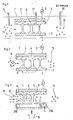
- the reactor 1 is shown schematically in FIG. In the embodiment shown here, it is formed by two electrodes 2 and 3, which are arranged vertically and area-wide from each other at a distance of a few millimeters.
- the two electrodes 2 and 3 are preferably rectangular and made of flat metal plates.
- the first electrode 2 is provided on its side facing the second electrode 2 with a dielectric layer 4, which in the exemplary embodiment shown here is made of glass.
- the two electrodes 2 and 3 are connected to a positive direct current source, one of the two electrodes 2 and 3 being connected to ground. Instead of a direct voltage or direct current source, a pulsed voltage can also be connected to the two electrodes.
- a plurality of small locally delimited, separate discharge zones 6 occurs between the two electrodes 2 and 3, in particular between the dielectric layer 4 and the second electrode 3.
- the exhaust gas 10 to be cleaned is introduced between the electrodes 2 and 3 and supplied to the discharge zones 6.
- the exhaust gas 10 to be cleaned is preferably introduced parallel to the longitudinal axis of the two electrodes 3 and 4.
- Chemical additives can be introduced into the reactor via lines 15, 16 and 17. According to the invention, such substances are introduced into the reactor which have oxidizing or reducing properties and convert the exhaust gas components NO x and / or SO 2 into usable end products by supporting the plasma.
- a suitable additive is, for example, ammonia. This allows ammonium sulfate or ammonium nitrate to be formed from the exhaust gas components.
- the reactor 1 can, if necessary, also have more than two electrodes be prepared, especially when large amounts of exhaust gas have to be cleaned.
- the invention there is the possibility of arranging a plurality of such electrodes 2 and 3 alternately with one another, so that an electrode 2 follows up and down an electrode 3, and this is followed by an electrode 2, etc.
- the electrodes 2, 3 in turn all have the same distance from one another.
- the electrodes 2 are also provided with a dielectric layer 4 on their surfaces facing the electrodes 3. A certain amount of exhaust gas can then be passed between two electrodes 2 and 3 for cleaning.
- the length of the electrodes 2 and 3 used, regardless of whether the reactor 1 consists of only two such electrodes or more, is preferably chosen between 0.1 and 1 m. If necessary, several such reactors can be connected in series to purify the exhaust gas, the exhaust gas to be cleaned being passed through the entire series connection of the reactors 1.
- the cleaned exhaust gas emerging from the reactor 1 is designated 11 here and in all other representations.
- the embodiment of the reactor shown in FIG. 2 has the same components as the embodiment shown in FIG. 1 and explained in the associated description. The same components are therefore provided with the same reference numerals. The difference is in the design of the electrode 3 and the supply of the exhaust gas.
- the elec trode 3 provided with openings 7 in some areas. These openings are arranged perpendicular to the longitudinal axis of the second electrode 3. They allow the exhaust gas to be cleaned to be fed into the area between the two electrodes 2 and 3, perpendicular to the longitudinal axis of these two electrodes. This makes it possible to introduce nitrogen gas 8 into the area between the electrodes 2 and 3 parallel to the longitudinal axis of the electrodes 2 and 3.
- atomic nitrogen can be generated from the introduced nitrogen gas 8, which is then used to reduce the nitrogen oxide contained in the exhaust gas 6.
- the mode of operation of the reactor 1 is further improved by the additional use of atomic nitrogen for the reduction of the nitrogen oxide.
- it can be used to purify exhaust gas that is loaded with large amounts of nitrogen oxide.
- the reactor 1 shown in FIG. 3 is particularly suitable for the purification of exhaust gases which, in addition to sulfur dioxide and nitrogen oxide, are additionally laden with dust.
- the reactor 1 shown in turn has two electrodes 2 and 3.
- the first electrode is formed by a metallic surface which has the same dimensions as the electrodes shown in FIGS. 1 and 2.
- the electrode 2 is coated on its side facing the second electrode 3 with a dielectric layer 4, in particular a glass layer.
- the electrode 2 is connected to a current source 5.
- the second electrode 3 is at a defined distance from this electrode 2, preferably at a distance of a few millimeters arranged that it is arranged parallel and area-wide to the first electrode 2.
- the second electrode 3 is designed as an endless belt.
- This endless belt has the same width as the electrode 2.
- the endless belt is movably supported and is guided over two 3W rollers for this purpose.
- One of the two rollers is connected to ground.
- the two rollers 3W are positioned and the dimensions of the electrode 3 are selected such that the surface of the electrode 3 facing the first electrode 2 has the same length as this.
- the surface of the electrode 3 is designed like a brush. In particular, 3 thin wires are arranged on the entire surface of the electrode so that they protrude perpendicularly from the surface.
- the exhaust gas 10 to be cleaned is introduced parallel to the longitudinal axis of the two electrodes 2 and 3 between them.
- a plurality of locally limited, separate discharge zones 6 * are formed between the two electrodes 2 and 3, the effects of which are exposed to the exhaust gas 10 to be cleaned.
- the dust contained in the exhaust gas 10 is transported due to the developing electric field to the second negatively charged electrode 3, where it is picked up by its brush-like surface.
- the electrode 3, which is designed as an endless belt, is moved continuously with the aid of the two rollers 3W, so that the dust which accumulates on the surface of the electrode 3 is constantly transported away from the area of the removal zones 6. On the rear side, the dust is then removed by washing or blowing the surface and supplied to a dust bunker 18 be passed so that the surface is then available for further use.
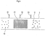
- FIG. 4 schematically shows a reactor 1, in particular its reaction zone 21.
- This reaction zone 21 can be designed, for example, as a tube and dimensioned such that it can be used as a section of an exhaust gas duct (not shown here).
- the plasma-generating arrangement is arranged within the reaction zone 21 in which the exhaust gas is cleaned. It is formed by a microwave or a high-frequency source, by an arc, spark or a so-called silent discharge arrangement. Via lines 31, 32 and 33, additives are introduced into the reaction zone which support the effect of the plasma generated.
Abstract
Description
Die Erfindung bezieht sich auf ein Verfahren zur Reinigung von Abgasen gemäß dem Oberbegriff des Patentanspruches 1 sowie auf eine Vorrichtung zur Durchführung des Verfahrens.The invention relates to a method for cleaning exhaust gases according to the preamble of
Ein solches Verfahren ist zur Reinigung von NOx-, S02-und staubhaltigen Abgasen aller Art geeignet, gleichgültig ob sie aus einer Verbrennungsmaschine oder einer Verbrennungsanlage kommen.Such a method is suitable for cleaning NO x , S0 2 and dust-containing exhaust gases of all kinds, regardless of whether they come from an internal combustion engine or an incineration plant.
Bekannt ist bereits ein Verfahren, bei dem mit Hilfe von Elektronenstrahlen Abgase aus Kraftwerken gereinigt werden können. Bei diesem Electron-Beam-Dry-Scrubber-Verfahren werden die Elektronen in einem Vakuum bei 10-6 Torr erzeugt und auf hohe Energien beschleunigt. Anschließend werden sie durch eine gekühlte Folie in den Reaktor geschossen, durch welchen das zu reinigende Abgas geleitet wird. Ein Teil der eingespeisten Energie geht als Verlustwärme in der Folie verloren. Von Nachteil ist bei diesem Verfahren, daß es energieaufwendig und deshalb kostenintensiv ist.A method is already known in which exhaust gases from power plants can be cleaned with the aid of electron beams. In this electron-beam-Dry Scrubber method, the electrons are generated in a vacuum at 10 -6 torr and accelerated to high energies. They are then shot through a cooled film into the reactor through which the exhaust gas to be cleaned is passed. Some of the energy fed in is lost as heat loss in the film. The disadvantage of this method is that it is energy-intensive and therefore expensive.
Der Erfindung liegt deshalb die Aufgabe zugrunde ein Verfahren aufzuzeigen, mit dem NOx-, S02- und staubhaltige Abgase jeder Art sehr billig gereinigt werden können.The invention is therefore based on the object of demonstrating a method with which NO x , S0 2 and dust Exhaust gases of any kind can be cleaned very cheaply.
Diese Aufgabe wird erfindungsgemäß durch die kennzeichnenden Merkmale des Patentanspruches 1 gelöst.This object is achieved by the characterizing features of
Zwei Vorrichtungen zur Durchführung des Verfahrens sind in den Patentansprüchen 4 und 7 offenbart.Two devices for performing the method are disclosed in
Mit dem erfindungsgemäßen Verfahren ist es möglich die im Abgas enthaltenen Anteile an NOX und S02 chemisch umzusetzen. Je nach Prozessführung und zugehöriger apparativer Gestaltung der Reinigungsanlagen können insbesondere NO reduziert und S02- oxidiert oder beide Gase oxidiert werden. Die bei dieser Reaktion gebildeten Zwischenprodukte, z.B. H2SO4 oder HN03 können kondensiert werden oder durch Zugabe von Ammoniak in Awmoniumsulfat bzw. Ammoniumnitrat umgewandelt werden. Andere Zusätze mit oxidierendem oder reduzierendem Charakter sind ebenfalls möglich. Der in dem Abgas enthaltene Staub wird mit Hilfe des ausgebildeten elektrischen Feldes aus dem Abgas abgeschieden.With the method according to the invention, it is possible to chemically convert the proportions of NO x and SO 2 contained in the exhaust gas. Depending on the process control and the associated apparatus design of the cleaning systems, NO in particular can be reduced and S0 2 -oxidized or both gases can be oxidized. The intermediates formed in this reaction, for example H 2 SO 4 or HN0 3, can be condensed or converted into ammonium sulfate or ammonium nitrate by adding ammonia. Other additives with an oxidizing or reducing character are also possible. The dust contained in the exhaust gas is separated from the exhaust gas with the aid of the electrical field that is formed.
Für die Durchführung des Verfahrens wird ein Reaktor verwendet, der zwei flächige Elektroden aufweist, die in definiertem Abstand parallel zueinander angeordnet sind. Eine der beiden Elektroden ist auf ihrer der zweiten Elektrode zugewandten Seite mit einem dielektrischen Werkstoff vorzugsweise Glas beschichtet. An die beiden Elektroden wird eine Gleich- oder gepulste Wechselspannung angelegt, derart, daß es zur Ausbildung mehrer voneinander getrennter, lokal begrenzter Entladungszonen,insbesondere zur Bildung kleiner Plasmazonen kommt. Durch diese Entladungszonen wird das zu reinigende Abgas wenigstens teilweise hindurchgeschickt. Erfindungsgemäß ist die der dielektrischen Schicht der ersten Elektrode gegenüberliegende zweite Elektrode mit Löchern versehen, über welche das Abgas zwischen die beiden Elektroden eingeleitet werden kann. Es besteht die Möglichkeit, die zweite Elektrode auch geschlossen auszubilden und das zu reinigende Abgas parallel zur Längsachse der beiden Elektroden in den Bereich zwischen diesen einzuleiten. Erfindungsgemäß sind die beiden den Reaktor bildenden Elektroden rechteckig ausgebildet. Über eine oder mehrere Leitungen können Zusätze in Form von Ammoniak oder anderen oxidierenden oder reduzierenden chemischen Verbindungen in den Reaktor, insbesondere in den Bereich zwischen den Elektroden bzw. vor oder hinter diesen eingeleitet werden.For the implementation of the method, a reactor is used which has two flat electrodes which are arranged parallel to one another at a defined distance. One of the two electrodes is coated on its side facing the second electrode with a dielectric material, preferably glass. A direct or pulsed alternating voltage is applied to the two electrodes in such a way that multiple, locally delimited discharge zones are formed, in particular small plasma zones. Because of these discharge zones this becomes cleaning exhaust gas sent at least partially. According to the invention, the second electrode opposite the dielectric layer of the first electrode is provided with holes through which the exhaust gas can be introduced between the two electrodes. It is also possible to design the second electrode as closed and to introduce the exhaust gas to be cleaned parallel to the longitudinal axis of the two electrodes into the area between them. According to the invention, the two electrodes forming the reactor are rectangular. Additions in the form of ammonia or other oxidizing or reducing chemical compounds can be introduced into the reactor, in particular into the area between the electrodes or in front of or behind them, via one or more lines.
Erfindungsgemäß kann die zweite der dielektrischen Schicht gegenüberliegende Elektrode als bewegliches Endlosband ausgebildet, das eine bürstenartige Oberfläche aufweist. Beim Anlegen einer Gleichspannung zwischen den beiden Elektroden, insbesondere beim Anlegen einer negativen Spannung an diese bewegliche Elektrode wird der im Abgas enthaltene Staub zu dieser Elektrode hinbewegt, und von ihrer bürstenartigen Oberfläche aufgenommen. Der Staub kann aus der bürstenartigen Oberfläche ausgewaschen, abgesaugt oder von ihr abgekratzt werden.According to the invention, the second electrode opposite the dielectric layer can be designed as a movable endless belt which has a brush-like surface. When a direct voltage is applied between the two electrodes, in particular when a negative voltage is applied to this movable electrode, the dust contained in the exhaust gas is moved towards this electrode and is picked up by its brush-like surface. The dust can be washed out of the brush-like surface, vacuumed or scraped off by it.
Außer der geschilderten Anordnung zur Erzeugung eines Plasmas bzw. vieler Microplasmen, können auch andere Plasmaquellen wie Microwellen, Hochfrequenzwellen, Bogen- oder Korona-Entladungen zur Erzeugung solcher Entladungszonen verwendet werden.In addition to the arrangement described for generating a plasma or many microplasmas, other plasma sources such as microwaves, high-frequency waves, arc or corona discharges can also be used to generate such discharge zones.
Das erfindungsgemäße Verfahren kann auch zur selektiven Entstickung von zuvor entschwefelten Abgasen verwendet werden. In diesem Fall wird der Reaktor hinter die Entschwefelungsanlage geschaltet.The method according to the invention can also be used for the selective denitrification of previously desulfurized exhaust gases. In this case, the reactor is connected behind the desulfurization plant.
Die zur Reinigung des Abgases in dem erfindungsgemäßen Reaktor verwendeten Elektronen bedürfen keiner hohen Beschleunigungsenergie. Die Verwendung von Vakuumelektronenkanonen zur Erzeugung von Elektronen mit hoher Energie sind deshalb nicht erforderlich, so daß die Reinigung des Abgases sehr kostengünstig durchgeführt werden kann. Die Entladung zwischen den Elektroden des Reaktors erfolgt mit einer sehr niedrigen Leistungsflächendichte. Zur Reinigung großer Rauchgasmengen werden Flächen benötigt, welche die Dimension des Querschnittes der Rauchgasleitung aufweisen.The electrons used to purify the exhaust gas in the reactor according to the invention do not require high acceleration energy. The use of vacuum electron guns for generating electrons with high energy is therefore not necessary, so that the cleaning of the exhaust gas can be carried out very inexpensively. The discharge between the electrodes of the reactor takes place with a very low power density. For cleaning large amounts of flue gas, areas are required which have the dimension of the cross section of the flue gas line.
Die Erfindung wird nachfolgend anhand von Zeichnungen erläutert.The invention is explained below with reference to drawings.
Es zeigen:
- Figur 1: Einen Vertikalschnitt durch einen Reaktor zur Reinigung von Abgasen,
- Figur 2: eine Variante des in
Figur 1 gezeigten Reaktors, - Figur 3: eine weitere Ausführungsform des erfindungsgemäßen Reaktors.
- Figur 4: eine dritte Variante eines Reaktors
- FIG. 1: a vertical section through a reactor for cleaning exhaust gases,
- FIG. 2: a variant of the reactor shown in FIG. 1,
- Figure 3: a further embodiment of the reactor according to the invention.
- Figure 4: a third variant of a reactor
In Figur 1 ist der erfindungsgemäße Reaktor 1 schematisch dargestellt. Bei dem hier gezeigten Ausführungsbeispiel wird er durch zwei Elektroden 2 und 3 gebildet, die in einem Abstand von wenigen Millimetern senkrecht und flächendeckend voneinander angeordnet sind. Die beiden Elektroden 2 und 3 sind vorzugsweise rechteckig ausgebildet und aus flächigen Metallplatten gefertigt. Die erste Elektrode 2 ist auf ihrer der zweiten Elektrode 2 zugewandten Seite mit einer dielektrischen Schicht 4 versehen, die bei dem hier dargestellten Ausführungsbeipiel aus Glas gefertigt ist. Die beiden Elektroden 2 und 3 sind mit einer positiven Gleichstromquelle verbunden, wobei eine der beiden Elektroden 2 und 3 an Masse angeschlossen ist. Anstelle einer Gleichspannungs- bzw. Gleichstromquelle kann an die beiden Elektroden auch an eine gepulste Spannung angeschlossen werden. In beiden Fällen kommt es zwischen den beiden Elektroden 2 und 3, insbesondere zwischen der dielektrischen Schicht 4 und der zweiten Elektrode 3, zur Ausbildung mehrerer kleiner lokal begrenzter, voneinander getrennter Entladungszonen 6. Das zu reinigende Abgas 10 wird zwischen die Elektroden 2 und 3 eingeleitet und den Entladungszonen 6 zugeführt. Die Einleitung des zu reinigenden Abgases 10 erfolgt vorzugsweise parallel zur Längsachse der beiden Elektroden 3 und 4. Über die Leitungen.15,16 und 17 können chemische Zusatzstoffe in den Reaktor eingeleitet werden. Erfindungsgemäß werden solche Stoffe in den Reaktor eingeleitet, die oxidierende oder reduzierende Eigenschaften besitzen und durch Unterstützung des Plasmas die Abgaskomponenten NOx und/oder S02 in verwertbare Endprodukte umsetzen. Ein geeigneter Zusatzstoff ist beispielsweise Ammoniak. Damit kann aus den Abgaskomponenten Ammoniumsulfat bzw. Ammoniumnitrat gebildet wird.The
Anstelle der beiden Elektroden 2 und 3 kann der Reaktor 1 bei Bedarf auch mit mehr als zwei Elektroden ausgerüstet werden, insbesondere dann, wenn große Mengen an Abgas zu reinigen sind. Erfindungsgemäß besteht die Möglichkeit eine Vielzahl solcher Elektrode 2 und 3 alternierend untereinander anzuordnen, so daß auf eine Elektrode 2 nach oben und untenhin eine Elektrode 3 folgt, und sich an diese wieder eine Elektrode 2 anschließt usw. Bei Verwendung mehrerer solcher Elektroden 2 und 3 zur Bildung eines Reaktors 1 weisen die Elektroden 2,3 alle wiederum den gleichen Abstand voneinander auf. Die Elektroden 2 sind auf ihren den Elektroden 3 zugewandten Oberflächen auch hierbei mit einer dielektrischen Schicht 4 versehen. Zwischen jeweils zwei Elektroden 2 und 3 kann dann eine gewisse Menge an Abgas zur Reinigung hindurchieleitet werden. Die Länge der verwendeten Elektroden 2 und 3 wird, gleichgültig ob der Reaktor 1 nur aus zwei solcher Elektroden oder mehreren besteht, vorzugsweise zwischen 0,1 und 1 m gewählt. Im Bedarfsfall können mehrere solcher Reaktoren zur Reinigung des Abgases hintereinander geschaltet werden, wobei das zu reinigende Abgas durch die gesamte Reihenschaltung der Reaktoren 1 hindurchgeleitet wird.Instead of the two
Das gereinigte aus dem Reaktor 1 austretende Abgas ist hier und bei allen anderen Darstellungen mit 11 bezeichnet.The cleaned exhaust gas emerging from the
Die in Figur 2 dargestellte Ausführungsform des Reaktors weist die gleichen Bauteile auf, wie die in Figur 1 dargestellte und in der zugehörigen Beschreibung erläuterte Ausführungsform. Gleiche Bauteile sind deshalb mit gleichen Bezugszeichen versehen. Der Unterschied besteht in der Ausbildung der Elektrode 3 und der Zuführung des Abgases. Wie Figur 2 zeigt, ist die Elektrode 3 bereichsweise mit Öffnungen 7 versehen. Diese Öffnungen sind senkrecht zur Längsachse der zweiten Elektrode 3 angeordnet. Sie ermöglichen die Zuführung des zu reinigenden Abgases in den.Bereich zwischen den beiden Elektroden 2 und 3, und zwar senkrecht zur Längsachse dieser beiden Elektroden. Dadurch ist die Möglichkeit gegeben, parallel zur Längsachse der Elektroden 2 und 3 Stickstoffgas 8 in den Bereich zwischen den Elektroden 2 und 3 einzuführen. Durch diese Maßnahme kann aus dem eingeleiteten Stickstoffgas 8 atomarer Stickstoff erzeugt wird, der dann zur Reduktion des im Abgas 6 enthaltenen Stickoxids herangezogen wird. Durch die zusätzliche Verwendung von atomarem Stickstoff für die Reduktion des Stickoxids wird die Wirkungsweise des Reaktors 1 noch verbessert. Insbesondere kann hiermit Abgas gereinigt werden, das mit großen Mengen an Stickoxid beladen ist. Durch Verwendung dieses Reaktors wird sichergestellt, daß ein solches.Abgas nach der Reinigung vollständig von`Stickoxid befreit ist.The embodiment of the reactor shown in FIG. 2 has the same components as the embodiment shown in FIG. 1 and explained in the associated description. The same components are therefore provided with the same reference numerals. The difference is in the design of the
Der in Figur 3 dargestellte Reaktor 1 ist insbesondere für die Reinigung von Abgasen geeignet, die neben Schwefeldioxid, Stickoxid zusätzlich mit Staub beladen sind. Der dargestellte Reaktor 1 weist wiederum zwei Elektroden 2 und 3 auf. Die erste Elektrode wird durch eine metallisch Fläche gebildet, welche die gleichen Abmessungen aufweist, wie die in den Fingur 1 und 2 dargestellten Elektroden. Die Elektrode 2 ist auf ihrer der zweiten Elektrode 3 zugewandten Seite mit einer dielektrischen Schicht 4, insbesondere einer Glasschicht überzogen. Zusätzlich ist die Elektrode 2 an eine Stromquelle 5 angeschlossen. In definiertem Abstand von dieser Elektrode 2, vorzugsweise in einem Abstand von wenigen Millimetern ist die zweite Elektrode 3 so angeordnet, daß sie parallel und flächendeckend zur ersten Elektrode 2 angeordnet ist.The
Die zweite Elektrode 3 ist, wie Figur 3 zeigt, als End-' losband ausgebildet. Dieses Endlosband weist die gleiche Breite wie die Elektrode 2 auf. Das Endlosband ist beweglich gehaltert und zu diesem Zweck über zwei Walzen 3W geführt. Eine der beiden Walzen ist an Masse angeschlossen. Die beiden Walzen 3W sind so positioniert und die Abmessungen der Elektrode 3 so gewählt, daß die der ersten Elektrode 2 zugewandte Oberfläche der Elektrode 3 die gleiche Länge wie diese aufweist. Die Oberfläche der Elektrode 3 ist bürstenartig ausgebildet. Insbesondere sind auf der gesamten Oberfläche der Elektrode 3 dünne Drähte so angeordnet, daß sie senkrecht von der Oberfläche abstehen.As shown in FIG. 3, the
Das zu reinigende Abgas 10 wird parallel zur Längsachse der beiden Elektroden 2 und 3 zwischen diese eingeleitet. Durch den Anschluß der Stromquelle 5 werden zwischen den beiden Elektroden 2 und 3 mehrere lokal begrenzte, voneinander getrennte Entladungszonen 6· ausgebildet, deren Wirkungen das zu reinigende Abgas 10 ausgesetzt wird. Der im Abgas 10 enthaltene Staub wird aufgrund des sich ausbildenden elektrischen Feldes zu der zweiten negativ geladenen Elektrode 3 transportiert und dort von deren bürstenartiger Oberfläche aufgenommen. Die als Endlosband ausgebildete Elektrode 3 wird mit Hilfe der beiden Walzen 3W kontinuierlich bewegt, so daß der sich auf der Oberfläche der Elektrode 3 ansammelnde Staub ständig aus dem Bereich der Entlandungszonen 6 abtransportiert wird. Auf der rückwärtigen Seite wird der Staub dann durch Waschen oder Beblasen der Oberfläche abgenommen und einem Staubbunker 18 zugeleitet werden, so daß die Oberfläche anschließend für eine weitere Benutzung wiederum zur Verfügung steht.The
Figur 4 zeigt schematisch einen Reaktor 1, insbesondere dessen Reaktionszone 21. Diese Reaktionszone 21 kann beispielsweise als Rohr ausgebildet und so bemessen sein, daß sie als Teilstück eines Abgaskanals, (hier nicht dargestellt) verwendet werden kann. Die plasmaerzeugende Anordnung ist hierbei innerhalb der Reaktionszone 21 angeordnet, in der das Abgas gereinigt wird. Sie wird durch eine Mikrowellen- oder eine Hochfrequenzquelle, durch eine Bogen-, Funken- oder eine sogenannte stille Entladungsanordnung gebildet. Über die Leitungen 31,32 und 33 werden Zusatzstoffe in die Reaktionszone eingeleitet welche die Wirkung des erzeugten Plasmas unterstützen.FIG. 4 schematically shows a
Claims (9)
Applications Claiming Priority (2)
| Application Number | Priority Date | Filing Date | Title |
|---|---|---|---|
| DE19843414121 DE3414121A1 (en) | 1984-04-14 | 1984-04-14 | METHOD AND DEVICE FOR PURIFYING EXHAUST GASES |
| DE3414121 | 1984-04-14 |
Publications (2)
| Publication Number | Publication Date |
|---|---|
| EP0158823A2 true EP0158823A2 (en) | 1985-10-23 |
| EP0158823A3 EP0158823A3 (en) | 1988-01-07 |
Family
ID=6233573
Family Applications (1)
| Application Number | Title | Priority Date | Filing Date |
|---|---|---|---|
| EP85102807A Withdrawn EP0158823A3 (en) | 1984-04-14 | 1985-03-12 | Process and device for purifying exhaust gases |
Country Status (2)
| Country | Link |
|---|---|
| EP (1) | EP0158823A3 (en) |
| DE (1) | DE3414121A1 (en) |
Cited By (25)
| Publication number | Priority date | Publication date | Assignee | Title |
|---|---|---|---|---|
| WO1987002909A1 (en) * | 1985-11-08 | 1987-05-21 | The Florida State University | METHOD OF REMOVING SO2, NOx AND PARTICLES FROM GAS MIXTURES USING STREAMER CORONA |
| US4735633A (en) * | 1987-06-23 | 1988-04-05 | Chiu Kin Chung R | Method and system for vapor extraction from gases |
| EP0356684A2 (en) * | 1988-08-01 | 1990-03-07 | Matsushita Electric Industrial Co., Ltd. | Electrostatic dust collector for use in vacuum system |
| EP0366876A1 (en) * | 1988-10-05 | 1990-05-09 | Mitsubishi Jukogyo Kabushiki Kaisha | Exhaust gas treating apparatus |
| DE3900005A1 (en) * | 1989-01-02 | 1990-07-05 | Ruhrgas Ag | Process for reducing nitrogen oxides in exhaust gases |
| EP0402142A1 (en) * | 1989-06-07 | 1990-12-12 | Satiko Okazaki | Process for removing NOx from exhaust gas using electric discharge |
| EP0423384A1 (en) * | 1989-10-16 | 1991-04-24 | Otis Elevator Company | Control arrangement for an elevator system without a speed sensor |
| US5125124A (en) * | 1988-08-01 | 1992-06-30 | Matsushita Electric Industrial Co., Ltd. | Electrostatic dust collector for use in vacuum system |
| WO1992020433A1 (en) * | 1991-05-21 | 1992-11-26 | Institute Of Nuclear Chemistry And Technology | A PROCESS FOR REMOVAL OF SO2 AND NOx FROM COMBUSTION FLUE GASES AND AN APPARATUS USED THEREFOR |
| WO1995025597A1 (en) * | 1994-03-24 | 1995-09-28 | Abb Management Ag | Process for conditioning waste gases |
| US5468356A (en) * | 1991-08-23 | 1995-11-21 | The United States Of America As Represented By The Secretary Of The Navy | Large scale purification of contaminated air |
| WO1996037690A1 (en) * | 1995-05-23 | 1996-11-28 | Fraunhofer-Gesellschaft zur Förderung der angewandten Forschung e.V. | Process and device for treating exhaust gas |
| WO1997003746A1 (en) * | 1995-07-14 | 1997-02-06 | Siemens Aktiengesellschaft | Process and device for the plasma-chemical decomposition and/or destruction of harmful substances |
| WO1997040265A1 (en) * | 1996-04-23 | 1997-10-30 | Fraunhofer-Gesellschaft zur Förderung der angewandten Forschung e.V. | Process and device for treating waste gas |
| US5817283A (en) * | 1996-09-06 | 1998-10-06 | Dravo Lime Company | Method for removing sulfur dioxide and nitrogen oxides from combustion gases |
| US6045618A (en) * | 1995-09-25 | 2000-04-04 | Applied Materials, Inc. | Microwave apparatus for in-situ vacuum line cleaning for substrate processing equipment |
| WO2000057992A1 (en) * | 1999-03-25 | 2000-10-05 | Fraunhofer-Gesellschaft zur Förderung der angewandten Forschung e.V. | Device and method for treating flowing gases, especially exhaust gases |
| US6187072B1 (en) | 1995-09-25 | 2001-02-13 | Applied Materials, Inc. | Method and apparatus for reducing perfluorocompound gases from substrate processing equipment emissions |
| US6193802B1 (en) | 1995-09-25 | 2001-02-27 | Applied Materials, Inc. | Parallel plate apparatus for in-situ vacuum line cleaning for substrate processing equipment |
| US6194628B1 (en) | 1995-09-25 | 2001-02-27 | Applied Materials, Inc. | Method and apparatus for cleaning a vacuum line in a CVD system |
| US6255222B1 (en) | 1999-08-24 | 2001-07-03 | Applied Materials, Inc. | Method for removing residue from substrate processing chamber exhaust line for silicon-oxygen-carbon deposition process |
| US6354241B1 (en) | 1999-07-15 | 2002-03-12 | Applied Materials, Inc. | Heated electrostatic particle trap for in-situ vacuum line cleaning of a substrated processing |
| US6576202B1 (en) | 2000-04-21 | 2003-06-10 | Kin-Chung Ray Chiu | Highly efficient compact capacitance coupled plasma reactor/generator and method |
| DE102010044252B4 (en) * | 2010-09-02 | 2014-03-27 | Reinhausen Plasma Gmbh | Apparatus and method for generating a barrier discharge in a gas stream |
| US9586178B2 (en) | 2014-04-17 | 2017-03-07 | General Electric Company | System and method for reducing nitrogen oxide in exhaust |
Families Citing this family (7)
| Publication number | Priority date | Publication date | Assignee | Title |
|---|---|---|---|---|
| DE4423397C2 (en) * | 1993-12-23 | 1999-03-11 | Fraunhofer Ges Forschung | Process and device for exhaust gas purification |
| DE19645689B4 (en) * | 1996-11-06 | 2006-05-11 | Bayerische Motoren Werke Ag | Device for exhaust aftertreatment for an internal combustion engine, in particular Otto engine with lean operation |
| FR2762524B1 (en) * | 1997-04-25 | 1999-07-09 | Electricite De France | PROCESS FOR TREATMENT OF GASEOUS EFFLUENTS LOADED WITH VOLATILE POLLUTANT COMPOUNDS BY REACTION OF SAID POLLUTANT COMPOUNDS WITH A PLASMA OUT OF THERMODYNAMIC BALANCE, AND REACTOR IN WHICH THIS PROCESS IS USED |
| DE10337901A1 (en) * | 2003-08-18 | 2005-03-24 | Audi Ag | Ammonia synthesis from hydrocarbons and air, especially for use in purifying combustion engine exhaust gases, by conversion to reformate gas followed by plasma-catalyzed reaction |
| DE102018214388A1 (en) * | 2018-08-24 | 2020-02-27 | Volkswagen Aktiengesellschaft | Plasma generating device for cleaning exhaust air loaded with organic compounds and / or substances |
| DE102018214387A1 (en) * | 2018-08-24 | 2020-02-27 | Volkswagen Aktiengesellschaft | Device for cleaning exhaust air loaded with organic compounds and / or substances, method for operating the device |
| DE102022119864A1 (en) | 2022-08-08 | 2024-02-08 | Manhal GbR ( vertretungsberechtigter Gesellschafter : Manhal Aogastin, 73102 Birenbach; Michael Funk, 73033 Göppingen; Margit Müller, 73084 Salach; Alexander Müller, 73072 Donzdorf; Markus Nille, 73072 Donzdorf | Filter system |
Citations (4)
| Publication number | Priority date | Publication date | Assignee | Title |
|---|---|---|---|---|
| DE2227949A1 (en) * | 1971-06-09 | 1973-01-04 | Monsanto Co | PROCEDURE FOR THE DECOMPOSITION OF NITROGEN OXIDES |
| JPS5310366A (en) * | 1976-07-16 | 1978-01-30 | Nippon Steel Corp | Treating method for nitrogen oxide in gas |
| DE2642751B2 (en) * | 1976-09-23 | 1978-11-30 | Cillichemie Ernst Vogelmann, 7100 Heilbronn | Device for generating ozone |
| JPS5570350A (en) * | 1978-11-17 | 1980-05-27 | Matsushita Electric Ind Co Ltd | Manufacturing method for catalyst |
-
1984
- 1984-04-14 DE DE19843414121 patent/DE3414121A1/en not_active Withdrawn
-
1985
- 1985-03-12 EP EP85102807A patent/EP0158823A3/en not_active Withdrawn
Patent Citations (4)
| Publication number | Priority date | Publication date | Assignee | Title |
|---|---|---|---|---|
| DE2227949A1 (en) * | 1971-06-09 | 1973-01-04 | Monsanto Co | PROCEDURE FOR THE DECOMPOSITION OF NITROGEN OXIDES |
| JPS5310366A (en) * | 1976-07-16 | 1978-01-30 | Nippon Steel Corp | Treating method for nitrogen oxide in gas |
| DE2642751B2 (en) * | 1976-09-23 | 1978-11-30 | Cillichemie Ernst Vogelmann, 7100 Heilbronn | Device for generating ozone |
| JPS5570350A (en) * | 1978-11-17 | 1980-05-27 | Matsushita Electric Ind Co Ltd | Manufacturing method for catalyst |
Non-Patent Citations (2)
| Title |
|---|
| PATENT ABSTRACTS OF JAPAN, Band 4, Nr. 113 (C-21)[595], 13. August 1980; & JP-A-55 070 350 (MATSUSHITA DENKI SANGYO K.K.) 27.05.1980 * |
| PATENT ABSTRACTS, Band 2, Nr. 52 (C-78)[214], 14. April 1978; & JP-A53 010 366 (SHIN NIPPON SEITETSU) 30.01.1978 * |
Cited By (37)
| Publication number | Priority date | Publication date | Assignee | Title |
|---|---|---|---|---|
| WO1987002909A1 (en) * | 1985-11-08 | 1987-05-21 | The Florida State University | METHOD OF REMOVING SO2, NOx AND PARTICLES FROM GAS MIXTURES USING STREAMER CORONA |
| US4735633A (en) * | 1987-06-23 | 1988-04-05 | Chiu Kin Chung R | Method and system for vapor extraction from gases |
| EP0296720A2 (en) | 1987-06-23 | 1988-12-28 | Kin-Chung Ray Chiu | Plasma extraction reactor and its use for vapor extraction from gases |
| US5125124A (en) * | 1988-08-01 | 1992-06-30 | Matsushita Electric Industrial Co., Ltd. | Electrostatic dust collector for use in vacuum system |
| EP0356684A2 (en) * | 1988-08-01 | 1990-03-07 | Matsushita Electric Industrial Co., Ltd. | Electrostatic dust collector for use in vacuum system |
| EP0356684A3 (en) * | 1988-08-01 | 1990-04-04 | Matsushita Electric Industrial Co., Ltd. | Electrostatic dust collector for use in vacuum system |
| EP0366876A1 (en) * | 1988-10-05 | 1990-05-09 | Mitsubishi Jukogyo Kabushiki Kaisha | Exhaust gas treating apparatus |
| DE3900005A1 (en) * | 1989-01-02 | 1990-07-05 | Ruhrgas Ag | Process for reducing nitrogen oxides in exhaust gases |
| EP0402142A1 (en) * | 1989-06-07 | 1990-12-12 | Satiko Okazaki | Process for removing NOx from exhaust gas using electric discharge |
| EP0423384A1 (en) * | 1989-10-16 | 1991-04-24 | Otis Elevator Company | Control arrangement for an elevator system without a speed sensor |
| WO1992020433A1 (en) * | 1991-05-21 | 1992-11-26 | Institute Of Nuclear Chemistry And Technology | A PROCESS FOR REMOVAL OF SO2 AND NOx FROM COMBUSTION FLUE GASES AND AN APPARATUS USED THEREFOR |
| US5468356A (en) * | 1991-08-23 | 1995-11-21 | The United States Of America As Represented By The Secretary Of The Navy | Large scale purification of contaminated air |
| US5478532A (en) * | 1991-08-23 | 1995-12-26 | The United States Of America As Represented By The Secretary Of The Navy | Large scale purification of contaminated air |
| WO1995025597A1 (en) * | 1994-03-24 | 1995-09-28 | Abb Management Ag | Process for conditioning waste gases |
| WO1996037690A1 (en) * | 1995-05-23 | 1996-11-28 | Fraunhofer-Gesellschaft zur Förderung der angewandten Forschung e.V. | Process and device for treating exhaust gas |
| WO1997003746A1 (en) * | 1995-07-14 | 1997-02-06 | Siemens Aktiengesellschaft | Process and device for the plasma-chemical decomposition and/or destruction of harmful substances |
| US6517913B1 (en) | 1995-09-25 | 2003-02-11 | Applied Materials, Inc. | Method and apparatus for reducing perfluorocompound gases from substrate processing equipment emissions |
| US6194628B1 (en) | 1995-09-25 | 2001-02-27 | Applied Materials, Inc. | Method and apparatus for cleaning a vacuum line in a CVD system |
| US6689930B1 (en) | 1995-09-25 | 2004-02-10 | Applied Materials Inc. | Method and apparatus for cleaning an exhaust line in a semiconductor processing system |
| US6045618A (en) * | 1995-09-25 | 2000-04-04 | Applied Materials, Inc. | Microwave apparatus for in-situ vacuum line cleaning for substrate processing equipment |
| US6680420B2 (en) | 1995-09-25 | 2004-01-20 | Applied Materials Inc. | Apparatus for cleaning an exhaust line in a semiconductor processing system |
| US6187072B1 (en) | 1995-09-25 | 2001-02-13 | Applied Materials, Inc. | Method and apparatus for reducing perfluorocompound gases from substrate processing equipment emissions |
| US6193802B1 (en) | 1995-09-25 | 2001-02-27 | Applied Materials, Inc. | Parallel plate apparatus for in-situ vacuum line cleaning for substrate processing equipment |
| WO1997040265A1 (en) * | 1996-04-23 | 1997-10-30 | Fraunhofer-Gesellschaft zur Förderung der angewandten Forschung e.V. | Process and device for treating waste gas |
| US5827488A (en) * | 1996-09-06 | 1998-10-27 | Dravo Lime Company | Process for removing SO2 and NOx from a gaseous stream |
| US5817283A (en) * | 1996-09-06 | 1998-10-06 | Dravo Lime Company | Method for removing sulfur dioxide and nitrogen oxides from combustion gases |
| US6461409B1 (en) | 1999-03-25 | 2002-10-08 | Fraunhofer-Gesellschaft Zur Foerderung Der Angewandten Forschung E.V. | Device and method for treating flowing gases, in particular exhaust gases |
| WO2000057992A1 (en) * | 1999-03-25 | 2000-10-05 | Fraunhofer-Gesellschaft zur Förderung der angewandten Forschung e.V. | Device and method for treating flowing gases, especially exhaust gases |
| US6354241B1 (en) | 1999-07-15 | 2002-03-12 | Applied Materials, Inc. | Heated electrostatic particle trap for in-situ vacuum line cleaning of a substrated processing |
| US6255222B1 (en) | 1999-08-24 | 2001-07-03 | Applied Materials, Inc. | Method for removing residue from substrate processing chamber exhaust line for silicon-oxygen-carbon deposition process |
| US6576202B1 (en) | 2000-04-21 | 2003-06-10 | Kin-Chung Ray Chiu | Highly efficient compact capacitance coupled plasma reactor/generator and method |
| US6998027B2 (en) | 2000-04-21 | 2006-02-14 | Dryscrub, Etc | Highly efficient compact capacitance coupled plasma reactor/generator and method |
| US7241428B2 (en) | 2000-04-21 | 2007-07-10 | Dryscrub, Etc | Highly efficient compact capacitance coupled plasma reactor/generator and method |
| DE102010044252B4 (en) * | 2010-09-02 | 2014-03-27 | Reinhausen Plasma Gmbh | Apparatus and method for generating a barrier discharge in a gas stream |
| US8696996B2 (en) | 2010-09-02 | 2014-04-15 | Reinhausen Plasma Gmbh | Device and method for generating a barrier discharge in a gas flow |
| US9586178B2 (en) | 2014-04-17 | 2017-03-07 | General Electric Company | System and method for reducing nitrogen oxide in exhaust |
| GB2529502B (en) * | 2014-04-17 | 2017-09-20 | Gen Electric | Plasma assisted nitrogen oxide (NOx) abatement system |
Also Published As
| Publication number | Publication date |
|---|---|
| DE3414121A1 (en) | 1985-10-24 |
| EP0158823A3 (en) | 1988-01-07 |
Similar Documents
| Publication | Publication Date | Title |
|---|---|---|
| EP0158823A2 (en) | Process and device for purifying exhaust gases | |
| DE3234100C2 (en) | Plasma arc device for applying coatings | |
| EP1902156B1 (en) | Method for treating plasma and/or covering plasma of workpieces under continuous atmospheric pressure | |
| DE2810735C2 (en) | Electric gas cleaning device | |
| DE2727973C2 (en) | Process for separating high-resistance dust from gases | |
| DE2838159A1 (en) | METHOD AND DEVICE FOR TREATING GASES LOADED WITH DIRTY PARTICLES | |
| DE112011102207B4 (en) | Reactive species feeder and surface treatment device | |
| DE112011102192B4 (en) | Reactive species feeder and surface treatment device | |
| DE2133173B2 (en) | Method and device for stripping an oxidized sheet metal strip | |
| DE4017120A1 (en) | BRIDGE CURRENT CORONA DISCHARGE GENERATOR | |
| DE2419265A1 (en) | DUST CHARGER FOR AN ELECTRIC DUST COLLECTOR | |
| DE4413118A1 (en) | Gas-cleaning apparatus | |
| CH673237A5 (en) | ||
| DE2462539A1 (en) | ELECTRIC DUST COLLECTING DEVICE | |
| EP0402798A2 (en) | Coating device | |
| DE3608291A1 (en) | Process for the selective or simultaneous separation of pollutants from flue gases by irradiating the flue gases with electron beams | |
| DE2639359A1 (en) | DEVICE FOR ELECTROSTATIC PARTICULAR SEPARATION | |
| DE2701640A1 (en) | IMPROVED DEVICE FOR MAINTAINING A DETERMINED ELECTRICALLY CHARGED ATMOSPHERIC | |
| WO1997014546A1 (en) | Device for treating flat substrates by a corona station | |
| DE2146539C3 (en) | Device for homogeneous charging or discharging of the surface of electrophotographic recording materials | |
| DE19913614C1 (en) | Electrical discharge method for treating exhaust fumes in which extensions on earthed electrode are perforated to allow passage of gas through them | |
| DE69723699T2 (en) | Process for cleaning a substrate and device for carrying out the process | |
| DE1597897B2 (en) | METHOD AND DEVICE FOR UNIFORM NEGATIVE CHARGING OF A SURFACE BY A CORONA DISCHARGE | |
| DE2151220C3 (en) | Device for electrostatic charging and separation of mass particles | |
| DE2341541A1 (en) | METHOD AND EQUIPMENT FOR ELECTROSTATIC PARTICULAR DEPOSITION |
Legal Events
| Date | Code | Title | Description |
|---|---|---|---|
| PUAI | Public reference made under article 153(3) epc to a published international application that has entered the european phase |
Free format text: ORIGINAL CODE: 0009012 |
|
| AK | Designated contracting states |
Designated state(s): BE FR GB NL |
|
| PUAL | Search report despatched |
Free format text: ORIGINAL CODE: 0009013 |
|
| AK | Designated contracting states |
Kind code of ref document: A3 Designated state(s): BE FR GB NL |
|
| STAA | Information on the status of an ep patent application or granted ep patent |
Free format text: STATUS: THE APPLICATION IS DEEMED TO BE WITHDRAWN |
|
| 18D | Application deemed to be withdrawn |
Effective date: 19880401 |
|
| RIN1 | Information on inventor provided before grant (corrected) |
Inventor name: SCHMIDT, CONRAD, DR. DIPL.-PHYS. |