EP0156599A1 - Composite carbon fibre and thermoplastic fiber blends - Google Patents
Composite carbon fibre and thermoplastic fiber blends Download PDFInfo
- Publication number
- EP0156599A1 EP0156599A1 EP85301791A EP85301791A EP0156599A1 EP 0156599 A1 EP0156599 A1 EP 0156599A1 EP 85301791 A EP85301791 A EP 85301791A EP 85301791 A EP85301791 A EP 85301791A EP 0156599 A1 EP0156599 A1 EP 0156599A1
- Authority
- EP
- European Patent Office
- Prior art keywords
- fiber
- tow
- fibers
- intermixing
- thermoplastic
- Prior art date
- Legal status (The legal status is an assumption and is not a legal conclusion. Google has not performed a legal analysis and makes no representation as to the accuracy of the status listed.)
- Granted
Links
Images

Classifications
-
- D—TEXTILES; PAPER
- D02—YARNS; MECHANICAL FINISHING OF YARNS OR ROPES; WARPING OR BEAMING
- D02G—CRIMPING OR CURLING FIBRES, FILAMENTS, THREADS, OR YARNS; YARNS OR THREADS
- D02G3/00—Yarns or threads, e.g. fancy yarns; Processes or apparatus for the production thereof, not otherwise provided for
- D02G3/22—Yarns or threads characterised by constructional features, e.g. blending, filament/fibre
- D02G3/40—Yarns in which fibres are united by adhesives; Impregnated yarns or threads
- D02G3/402—Yarns in which fibres are united by adhesives; Impregnated yarns or threads the adhesive being one component of the yarn, i.e. thermoplastic yarn
-
- A—HUMAN NECESSITIES
- A63—SPORTS; GAMES; AMUSEMENTS
- A63B—APPARATUS FOR PHYSICAL TRAINING, GYMNASTICS, SWIMMING, CLIMBING, OR FENCING; BALL GAMES; TRAINING EQUIPMENT
- A63B51/00—Stringing tennis, badminton or like rackets; Strings therefor; Maintenance of racket strings
- A63B51/02—Strings; String substitutes; Products applied on strings, e.g. for protection against humidity or wear
-
- B—PERFORMING OPERATIONS; TRANSPORTING
- B29—WORKING OF PLASTICS; WORKING OF SUBSTANCES IN A PLASTIC STATE IN GENERAL
- B29B—PREPARATION OR PRETREATMENT OF THE MATERIAL TO BE SHAPED; MAKING GRANULES OR PREFORMS; RECOVERY OF PLASTICS OR OTHER CONSTITUENTS OF WASTE MATERIAL CONTAINING PLASTICS
- B29B15/00—Pretreatment of the material to be shaped, not covered by groups B29B7/00 - B29B13/00
- B29B15/08—Pretreatment of the material to be shaped, not covered by groups B29B7/00 - B29B13/00 of reinforcements or fillers
- B29B15/10—Coating or impregnating independently of the moulding or shaping step
- B29B15/12—Coating or impregnating independently of the moulding or shaping step of reinforcements of indefinite length
-
- B—PERFORMING OPERATIONS; TRANSPORTING
- B29—WORKING OF PLASTICS; WORKING OF SUBSTANCES IN A PLASTIC STATE IN GENERAL
- B29C—SHAPING OR JOINING OF PLASTICS; SHAPING OF MATERIAL IN A PLASTIC STATE, NOT OTHERWISE PROVIDED FOR; AFTER-TREATMENT OF THE SHAPED PRODUCTS, e.g. REPAIRING
- B29C70/00—Shaping composites, i.e. plastics material comprising reinforcements, fillers or preformed parts, e.g. inserts
- B29C70/04—Shaping composites, i.e. plastics material comprising reinforcements, fillers or preformed parts, e.g. inserts comprising reinforcements only, e.g. self-reinforcing plastics
- B29C70/06—Fibrous reinforcements only
- B29C70/10—Fibrous reinforcements only characterised by the structure of fibrous reinforcements, e.g. hollow fibres
- B29C70/16—Fibrous reinforcements only characterised by the structure of fibrous reinforcements, e.g. hollow fibres using fibres of substantial or continuous length
- B29C70/20—Fibrous reinforcements only characterised by the structure of fibrous reinforcements, e.g. hollow fibres using fibres of substantial or continuous length oriented in a single direction, e.g. roofing or other parallel fibres
-
- B—PERFORMING OPERATIONS; TRANSPORTING
- B29—WORKING OF PLASTICS; WORKING OF SUBSTANCES IN A PLASTIC STATE IN GENERAL
- B29C—SHAPING OR JOINING OF PLASTICS; SHAPING OF MATERIAL IN A PLASTIC STATE, NOT OTHERWISE PROVIDED FOR; AFTER-TREATMENT OF THE SHAPED PRODUCTS, e.g. REPAIRING
- B29C70/00—Shaping composites, i.e. plastics material comprising reinforcements, fillers or preformed parts, e.g. inserts
- B29C70/04—Shaping composites, i.e. plastics material comprising reinforcements, fillers or preformed parts, e.g. inserts comprising reinforcements only, e.g. self-reinforcing plastics
- B29C70/28—Shaping operations therefor
- B29C70/40—Shaping or impregnating by compression not applied
- B29C70/50—Shaping or impregnating by compression not applied for producing articles of indefinite length, e.g. prepregs, sheet moulding compounds [SMC] or cross moulding compounds [XMC]
-
- B—PERFORMING OPERATIONS; TRANSPORTING
- B29—WORKING OF PLASTICS; WORKING OF SUBSTANCES IN A PLASTIC STATE IN GENERAL
- B29K—INDEXING SCHEME ASSOCIATED WITH SUBCLASSES B29B, B29C OR B29D, RELATING TO MOULDING MATERIALS OR TO MATERIALS FOR MOULDS, REINFORCEMENTS, FILLERS OR PREFORMED PARTS, e.g. INSERTS
- B29K2105/00—Condition, form or state of moulded material or of the material to be shaped
- B29K2105/0079—Liquid crystals
-
- B—PERFORMING OPERATIONS; TRANSPORTING
- B29—WORKING OF PLASTICS; WORKING OF SUBSTANCES IN A PLASTIC STATE IN GENERAL
- B29K—INDEXING SCHEME ASSOCIATED WITH SUBCLASSES B29B, B29C OR B29D, RELATING TO MOULDING MATERIALS OR TO MATERIALS FOR MOULDS, REINFORCEMENTS, FILLERS OR PREFORMED PARTS, e.g. INSERTS
- B29K2105/00—Condition, form or state of moulded material or of the material to be shaped
- B29K2105/06—Condition, form or state of moulded material or of the material to be shaped containing reinforcements, fillers or inserts
- B29K2105/08—Condition, form or state of moulded material or of the material to be shaped containing reinforcements, fillers or inserts of continuous length, e.g. cords, rovings, mats, fabrics, strands or yarns
- B29K2105/10—Cords, strands or rovings, e.g. oriented cords, strands or rovings
- B29K2105/101—Oriented
-
- B—PERFORMING OPERATIONS; TRANSPORTING
- B29—WORKING OF PLASTICS; WORKING OF SUBSTANCES IN A PLASTIC STATE IN GENERAL
- B29K—INDEXING SCHEME ASSOCIATED WITH SUBCLASSES B29B, B29C OR B29D, RELATING TO MOULDING MATERIALS OR TO MATERIALS FOR MOULDS, REINFORCEMENTS, FILLERS OR PREFORMED PARTS, e.g. INSERTS
- B29K2301/00—Use of unspecified macromolecular compounds as reinforcement
- B29K2301/12—Thermoplastic materials
-
- B—PERFORMING OPERATIONS; TRANSPORTING
- B29—WORKING OF PLASTICS; WORKING OF SUBSTANCES IN A PLASTIC STATE IN GENERAL
- B29K—INDEXING SCHEME ASSOCIATED WITH SUBCLASSES B29B, B29C OR B29D, RELATING TO MOULDING MATERIALS OR TO MATERIALS FOR MOULDS, REINFORCEMENTS, FILLERS OR PREFORMED PARTS, e.g. INSERTS
- B29K2307/00—Use of elements other than metals as reinforcement
-
- B—PERFORMING OPERATIONS; TRANSPORTING
- B29—WORKING OF PLASTICS; WORKING OF SUBSTANCES IN A PLASTIC STATE IN GENERAL
- B29L—INDEXING SCHEME ASSOCIATED WITH SUBCLASS B29C, RELATING TO PARTICULAR ARTICLES
- B29L2031/00—Other particular articles
- B29L2031/52—Sports equipment ; Games; Articles for amusement; Toys
- B29L2031/5245—Rackets
Definitions
- This invention relates to a fiber tow and to a process for preparing it. Such tows are useful in forming composite articles. More particularly, this invention involves the use of carbon fiber-containing fiber blends which are useful in preparing composite articles.
- U.S. Patent No. 4,226,079 discloses the combining of two different types of fibers, in order to produce a bulk yarn.
- the fibers are intermixed in a jet intermixing zone.
- the fibers disclosed in the patent are polyester and polyamid fibers. There is no suggestion of combining carbon and thermoplastic fibers.
- U.S. Patent No. 3,175,351 discloses a method of bulking continuous filament yarns.
- the two yarns which are combined may be of different compositions.
- any of the yarns might be a carbon fiber yarn.
- U.S. Patent No. 3,859,158 discloses the preparation of carbon fiber reinforced composite articles by forming an;open weave of a carbon fiber and coating with a carbonaceous material.
- U.S. Patent No. 4,368,234 discloses complex woven materials used for reinforcement which are formed from alternating bands of graphite fibers and low modulus fibers. The woven materials disclosed in this patent are subsequently impregnated with a thermosetting resin and cured.
- thermoplastic tapes were stiff and "boardy" and could not be draped across intricately shaped molds. While thermoset prepregs were somewhat more flexible, they were often quite tacky and difficult to handle. As a result, the use of both types of tapes was limited.
- the invention provides a continuous fiber tow useful in forming composite articles which comprises an intimate blend of 90 to 30% by volume, based on the total fiber content, of a spun thermoplastic fiber having a melting point of at least 50°C. and 10 to 70% by volume, based on the total fiber content, of a carbon fiber.
- the tows of the invention are capable of being formed into articles which have a very small radius of curvature.
- Such articles may for example have a radius of curvature of at least 0.002 inch (0.05 mm).
- the invention also provides a process for preparing a fiber tow useful in forming composite articles which comprises :
- the process of this invention involves (a) forming a carbon fiber tow from a multitude of carbon fibers; (b) forming a thermoplastic.polymeric fiber tow; (c) intermixing the two tows; and (d) withdrawing the intermixed tows for use.
- the intermixed tows may then be employed in forming various carbon fiber-containing composites.
- the fiber blends prepared according to the invention are flexible and handleable and have good draping properties, so that they can be used to form intricately shaped articles.
- good wetting of the carbon fiber by the thermoplastic material is obtained when appropriate heat and pressure are applied to the mold.
- Good wetting is obtained in large measure because of the substantially uniform distribution of the thermoplastic fiber and the carbon fiber within the fiber blend.
- the products of the invention find particular utility in end use applications where a small radius of curvature in the final product is desired. For example, using the prior art tapes, it was not possible in many instances to prepare articles which had 90° bend, because the tapes would crack or deform at the bend line. However, the tows of the invention may be employed with radii of curvature as low as 0.002 in (0.05 mm).
- thermoplastic polymers which are useful in carrying out the invention may belong to virtually any type of relatively high molecular weight thermoplastic polymer, including polyethylene, polypropylene, polyester, the various polyamides, polyimides, polyamidimides,polyetherimides,polysulfones (e.g. polyether sulfones),polyether ether ketones, polybutylene terephthalate and the like.
- the melting point of the polymer should generally be at least 50° F(28°C.) and preferably at least 200°F (111°C) above ambient conditions. Higher melting temperatures ensure that there will be no undue sticking or binding of the spun fibers prior to use.
- mixturetures of various thermoplastic polymers may also be employed to advantage where specific combinations of properties are desired.
- liquid crystal polymers or LCPs are the liquid crystal polymers or LCPs.
- these polymers include the wholly aromatic polyester resins which are discussed in the following publications: (a) Polyesters of Hydroxybenzoic Acids, by Russell Gilkey and John R. Caldewell, J. of Applied Polymer Sci., Vol. II, Pages 198 to 202 (1959),(b) Polyarylates (Polyesters From Aromatic Dicarboxylic Acids and Bisphenols), by G. Bier, Polymer, Vol.15, Pages 527 to 535 (March 1974), (c) Aromatic Polyester Plastics, by S.G.
- polyesters are disclosed, for instance, in (a) Polyester X7G-A Self Reinforced Thermoplastic, by W.J. Jackson, Jr., H.F. Kuhfuss, and T.F. Gray, Jr., 30th Anniversary Technical Conference, 1975 Reinforced Plastics/Composites Institute, The Society of the Plastics Industry,Inc., Section 17-D, Pages 1 to 4, (b) Belgian Patents Nos. 838,935 and 828,936, (c) Dutch Patent No. 7505551, (d) West German Patents Nos. 2520819, 2520820,27222120, 2834535,2834536 and 2834537, (e) Japanese Patents Nos.
- polyesters and copolyesters which are preferred consist essentially of structural units having recurring groups of the formula and and/or wherein units I and II, if present, are present in substantially equimolar amounts;
- R 1 ,R 2 and R 3 are radicals selected from (1) single and fused six-membered aromatic carbocyclic ring systems wherein the chain-extending bonds of the ring system if attached to the same ring, are positioned 1,3- or 1,4- (preferably 1,4-) to each other, and if attached to different rings, are preferably in positions parallel and oppositely directed, and (2) multiple six-membered aromatic carboxcyclic ring systems in which the individual rings are joined by a chemical bond or a trans-vinylene group and in which the chain extending bonds of each ring are in the 1, 3- or 1,4- (preferably 1,4-) positions;
- R 2 may also be wherein A is a divalent radical containing one or two bicyclic in-chain atoms; and
- R 3 may also be wherein the ali
- R 2 aromatic ring systems are also intended to include one or more substituents, e.g., chloro, bromo,fluoro, or lower alkyl (1-4 carbon atoms) on the ring or rings.
- the R 2 aromatic ring systems should preferably be unsubstituted when only one kind of unit I and one kind of unit II are used, i.e.,when a homopolymer is formed to ensure obtaining oriented fibers. In the case of copolymers, it is preferred that the R 2 aromatic ring systems be unsubstituted because of thermal or hydrolytic instability and/or cost of the R 2 -ring substituted copolymers.
- aromatic polymer-forming units i.e., units wherein the chain extending functional groups are attached to aromatic rings not conforming to those described above and which do not interfere with the anisotropic melt forming capability of the polymers.
- aromatic polymer-forming units i.e., units wherein the chain extending functional groups are attached to aromatic rings not conforming to those described above and which do not interfere with the anisotropic melt forming capability of the polymers.
- the (co)polyesters may comprise units I and II in substantially equimolar amounts or may comprise unit III or may comprise a combination of units I,II, and III, and, of course, more than one kind of unit (I,II and/or III) can be present in the polymer.
- Preferred (co)polyesters for use in the invention consist essentially of units 1 and II.
- R 1 is selected from 1,4-phenylene; chloro-, dichloro-,bromo-,dibromo-,methyl-, dimethyl-, and fluoro-1, 4-phenylene; 4,4'-biphenylene; 3,3',5,5' - tetramethyl-4,4'-biphenylene and R 2 is selected from trans-1,4-cyclohexylene; trans-2,5-dimethyl-1,4-cyclohexylene; trans-vinylenebis (1,4-phenylene); 4,4'-biphenylene; 2,6-naphthylene; and 1, 4-phenylene and with the proviso that more than one kind of unit I or II are present.
- the polymers consist essentially of the recurring units wherein X is selected from chloro-,bromo-,fluoro-, and methyl radicals; n is 1 or 2; and Y is selected from 4,4'-biphenylene and 2,6-naphthylene, the ratio of units beings within the range of 4:1 to 1:4.
- the polymers consist essentially of the recurring units and wherein Z is selected from 4,4' biphenylene,2,6-naphthylene, and 1,4-phenylene, the ratio of units being within the range of 4:1 to 3:2. With each type of polymer, up to 25 mol percent of non-conforming units may be present as described above.
- a list of useful dicarboxylic acids includes, for example terephthalic acid, 4,4'-bibenzoic acid, 4,4'-oxydi- benzoic acid, 4,4'-thiodibenzoic acid, 4-carboxyphenoxyacetic acid, 4,4'-trans-stilbenedicarboxylic acid, 2,6-naphthalenedicarboxylic acid, ethyleneoxy-4,4'-dibenzoic acid, isophthalic acid, the halogen and methyl substituted derivatives of the foregoing dicarboxylic acids, 1,4-trans-cyclohexanedicarboxylic acid and 2,5-dimethyl-1,4-trans-cyclohexanedicarboxylic acid.
- phenolic carboxylic acids includes 6-hydroxy-2-naphthoic acid, 4-hydroxy-4'carboxy azobenzene, ferulic acid, 4-hydroxybenzoic acid,4-(4'-hydroxy- phenoxy)-benzoic acid and 4-hydroxycinnamic acid and the alkyl, alkoxy and halogen substituted versions of these compounds.
- the (co)polyesters are prepared preferably by melt polycondensation of derivatives of dihydric phenols and aromatic aliphatic,aromatic and cycloaliphatic dicarboxylic acids or their derivatives .
- a convenient preparative method is the melt polycondensation of the diacetate of a dihydric phenol with a dicarboxylic acid.
- phenolic carboxylic acids or their derivatives may be used as coreactants in the preparation of polyesters and copolyesters.
- a list of useful dihydric phenols includes, for example hydroquinone, chloro- hydroquinone,bromohydroquinone, methylhydroquinone, dimethyl-hydroquinone, dichlorohydroquinone, dibromohydroquinone, 4,4'- oxydiphenol,4,4'-isopropylidenediphenol, 4,4'-thiodiphenol,4,4'-biphenol,3,5,3' ,5'-tetramethyl-4,4' -bisphenol, 3,5,3',5'- tetrachloro-4,4'-biphenol,2,6-dihydroxynaphthalene, 2,7-dihydroxynaphthalene, and 4,4'-methylenediphenol.
- anisotropic polymers by polymerizing methylacrycloxy benzoic acid utilizing an alkali metal hydroxide and free radical initiators as described in U.S. Patents Nos. 4,112,212,4,130,702 and 4,160,755.
- Useful phenolic-carboxylic acid derivatives include, for example p-acetoxybenzoic acid and p-acetoxy- cinnamic acid.
- polyesters and copolyesters includes: poly(methyl-1,4-phenylene 2,5-dimethyl- trans- hexahydroterephthalate):copoly(methyl-1,4-phenylene trans-hexa- hydroterephthalate/terephthalate) (8/2); copoly (chloro-1,4-phenylene trans-hexahydroterephthalate/isophtha- late) (9/1) and (8/2);copoly(ethyl-1,4-phenylene terephthalate/ 2,6-naphthalate) (7/3); copoly(tert.butyl-1,4-phenylene/3,3', 5,5'-tetramethyl-4,4'-bi-phenylene/terephthalate) (7/3); copoly(chloro-l,4-phenylene/-3,3',5,5'-tetrachloro-4,4'-biphenylene terephthalate) (7/3).
- liquid crystal polymers including wholly aromatic polyesters and poly(ester-amide)s which are suitable for use in the present invention may be formed by a variety of ester forming techniques involving reacting organic monomer compounds possessing functional groups which, upon condensation, form the requisite recurring moieties.
- the functional groups of the organic monomer compounds may be carboxylic acid groups, hydroxyl groups, ester groups, acryoxy groups, acid halides, amine groups, etc.
- the organic monomer compounds may be reacted in the absence of a heat exchange fluid via a melt acidolysis procedure. They, accordingly may be heated initially to form a melt solution of the reactants with the reaction continuing as said polymer particles are suspended therein. A vacuum may be applied to facilitate removal of volatiles formed during the final state of the condensation (e.g., acetic acid or water).
- the organic monomer reactants from which the wholly aromatic polyesters are derived may be initially provided in a modified form whereby the usual hydroxy groups of such monomers are esterified (i.e., they are provided as lower acyl esters).
- the lower acyl groups preferably have from two to four carbon atoms.
- the acetate esters of organic monomer reactants are provided.
- an amine group may be provided as a lower acyl amide.
- Representative catalysts which optionally may be employed in either the melt acidolysis procedure or in the slurry procedure of U.S. Patent No. 4,083,829 include dialkyl tin oxide (e.g. dibutyl tin oxide), diaryl tin oxide, titanium dioxide, antimony trioxide, alkoxy titanium silicates, titanium alkoxides, alkali and alkaline earth metal salts of carboxylic acids (e.g., zinc acetate), the gaseous acid catalysts such as Lewis acids (e.g. BF3), hydrogen halides (e.g. HCl), etc.
- the quantity of catalyst utilized typically is 0.001 tc 1 percent by weight based upon the total monomer weignt, and most commonly 0.01 to 0.2 percent by weight.
- the wholly aromatic polyesters and poly(ester-amide)s suitable for use in the present invention tend to be substantially insoluble in common polyester solvents and accordingly are not susceptible to solution processing. As discussed previously, they can be readily processed by common melt processing techniques. Most suitable wholly aromatic polymers are soluble in pentafluorophenol to a limited extent.
- the wholly aromatic polyesters which are preferred for use in the present invention commonly exhibit a weight average molecular weight of 2,000 to 200,000 and preferably 10,000 to 50,000, and most preferably 20,000 to 25,000.
- the wholly aromatic poly(ester-amides which are preferred for use in the present invention commonly exhibit a molecular weight of 5,000 to 50,000, and preferably 10,000 to 30,000; e.g., 15,000 to 17,000.
- Such molecular weight may be determined by gel permeation chromatography and other standard techniques not involving the dissolving of the polymer, e.g., by end group determination via infrared spectroscopy on compression molded films. Alternatively, light scattering techniques in a pentafluorophenol solution may be employed to determine the molecular weight.
- the wholly aromatic polyesters and poly(ester-amide)s additionally commonly exhibit an inherent viscosity(I.V.) of at least 2.0 dl./g.,e.g.,2.0 to 10.0 dl./g., when dissolved at a concentration of 0.1 percent by weight in pentafluorophenol at 60°C.
- I.V. inherent viscosity
- the aromatic rings which are included in the polymer backbones of the polymer components may include substitution of at least some of the hydrogen atoms present upon an aromatic ring.
- substituents include alkyl groups of up to four carbon atoms; alkoxy groups having up to four carbon atoms; halogens;and additional aromatic rings, such as phenyl and substituted phenyl.
- Preferred halogens include fluorine, chlorine and bromine. Although bromine: atoms tend to be released from organic compounds at high temperatures, bromine is more stable on aromatic rings than on aliphatic chains, and therefore is suitable for inclusion as a possible substituent on the aromatic rings.
- the fibers useful herein are basically carbon fibers which may be prepared by a variety of methods. Virtually any of the prior art methods of carbon fiber preparation may be employed in this invention.
- the fibers which may be formed into graphite or carbon fibers and are useful in this invention are those materials where the polymeric precursor is, for example, cellulose, acrylic derivatives, and, in particular, polyacrylonitriles.
- the acrylic polymer may contain not less than 85 mol percent of acrylonitrile units, with not more than 15 mol percent of a monovinyl compound which is copolymerizable with acrylonitrile, such as styrene, methylacrylate, methylmethacrylate,vinyl acetate, vinyl chloride, vinylidene chloride or vinyl pyridine.
- a monovinyl compound which is copolymerizable with acrylonitrile such as styrene, methylacrylate, methylmethacrylate,vinyl acetate, vinyl chloride, vinylidene chloride or vinyl pyridine.
- Other copolymerizable monomers include styrene sulfonic acid,allyl sulfonic acid, alky
- the carbon fibers which are particularly useful herein have bundle or tow deniers in the range of from 300-100,000 and filament counts of from 300-300,000, preferably deniers of 1,000-16,000 and filament counts of 3,000 -24,000. :
- the fibers also should exhibit a tensile strength of at least 100,000 psi (689 000 kPa) and a tensile modulus of 10 to 120 x 10 6 psi (68.9 to 826.8 x 10 6 kPa).
- thermoplastic fibers which are particularly useful herein have bundle cross-sectional areas ranging from twice that of the carbon fiber tows to half that of the carbon fiber tow.
- Bundle or tow denier will generally be in the range of 1 to 50 and the fiber count will depend upon single filament denier (higher counts are required with lower denier filaments). However, in general, from 10 to 1 50,000 filaments, preferably 100 to 10,000 filaments, are employed.
- the modulus of the fiber should be in the range of 50,000 to 500,000 psi (344,500 to 3,445,000 kPa).
- the thermoplastic fiber should also exhibit a melting point of at least 50° F (28°C), preferably at least 200°F (111°C), above ambient termperatures. And of course, the fiber should melt and fuse at temperatures no higher than 1,000 0 F (538°C), preferably no higher than 800°F (427°C), in order to be useful herein.
- the weight ratio of the two fibers which are intermixed can vary widely. However, in order to prepare satisfactory composites, it is necessary that sufficient thermoplastic polymer fiber be employed to obtain complete wetting of the carbon fibers. Generally, no less than 30 percent,by volume, of the thermoplastic polymer fibers may be employed. The maximum amount of thermoplastic polymer depends upon the strength properties which are required. In general, when less than ten percent, by volume, of the carbon fiber is present, the-resulting composite products have strength and stiffness properties which are poor in relation to products containing higher amounts of carbon fibers. Preferably 20 to 60 percent, by volume, of the carbon fiber material should be present in the combined tow.
- thermoplastic fibers which are used herein, it is possible to add to the fiber blends of the invention other non-thermoplastic fibers as reinforcing fibers.
- these materials include the various types of fiberglasses and ceramic fibers.
- a carbon fiber tow (1) is obtained having the properties specified above.
- the fibers from the carbon fiber tow are passed through a fiber guide (3) and onto a first Godet roll (4).
- the first Godet roll is synchronized with a second Godet roll (11) at rates of speed such that the second Godet roll revolves slightly slower than the first Godet roll.
- the fibers between the two Godet rolls which are subsequently spread and intermixed during the process of the invention, remains in a low tensioned (approaching tension-free) state which provides for effective fiber intermixing.
- thermoplastic polymer fibers such as polybutylene terephthalate fibers
- a tension comb may be employed after the fibers leave the bobbin and before they are brought into contact with the Godet roll. This tension comb serves to improve the contact of the fiber with the Godet roll and to increase the width of the fiber tow.
- the fiber comb having a plurality of spaced-apart fingers acts to maintain as separate the various fine yarns of the thermoplastic polymeric fiber so as to preserve separation of the individual fibers.
- the carbon fibers after heaving the fiber guide (5), are directed into a gas banding jet (7).
- the gas banding jet shown in Figs 3 and 4 is used to uniformly spread the fiber tows.
- a gas "banding" jet can also be used as an intermixing means whereby the gas jet serves to uniformly intermix the two fiber tows.
- the banding jet consists of a gas box (40) into which compressed air or another gas is fed through a conventional adjustable gas metering means (41).
- the preferred pressure of gas flow into the gas jet is in the range of 0.5 to 10 psi (3.45 to 68.9 kPa).
- One,or more than one, gas exit ports (44) are provided to cause gas from within the gas box to impinge in a generally perpendicular fashion upon the fiber tow which passes across the exit ports.
- the exit ports are V-shaped and pointed in the direction of movement of the fiber tow across the box.
- the gas banding jet is provided with shims (46) or other means to allow a gas box cover (48) to be attached, so that a flow channel for the fibers is provided.
- the gas box cover is held in place by convenient attachment means, such as clamps (49).
- thermoplastic fiber and the carbon fiber are subject to gas banding jet treatment (26) and (27).
- gas banding jet treatment such as polybutylene terephthalate
- a fiber comb having a plurality of spaced-apart fingers, as described above, may be employed in place of the banding jet.
- intermixing means is a pair of stationary rods or bars.
- the fibers from the spread carbon fiber tow and the fibers from the spread thermoplastic tow or yarns both initially come into contact together on the bottom of the first stationary rod or bar.
- the fibers then are deflected across the top of the second stationary bar or rod and, as a result, are intermixed.
- both fibers be uniformly spread across their entire width and that the area within which both fibers are spread be virtually identical.
- the fibers After intermixing, the fibers pass through a comb (9) to maintain dimensional stability ahd-through twist guides (10) to impart a slight twist to the intermixed fibers.
- the twist is imparted in order to maintain the intermixing of the fibers.
- false-twisting of the fibers using methods well known in the art may be employed.
- a fiber wrap may be used to hold the intermixed fibers together.
- the overwrap may be of any convenient type of fiber. However, it is preferred that the overwrap consist of a relatively small quantity of thermoplastic fibers.
- the mixed fibers are then wrapped around a second Godet roll (11) which, as pointed out above, serves in con- juncticn with the first Godet roll to provide a relatively tension-free zone to allow fiber intermixing.
- the fibers are then taken up by a takeup roll (12) for storage.
- a takeup roll (12) for storage.
- the intermixed fibers may be made stable by application of an appropriate fiber finish which serves to hold the intermixed fibers together and enable easier handling in subsequent operations, such as weaving.
- Fig. 2 is similar to Fig.1 but is the process most preferred when a liquid crystal type polymer or other higher melting point polymer is used.
- a carbon fiber roll (21) feeds carbon fiber through tension comb (22) and onto Godet roll (25).
- Liquid crystal fibers from a roll (23) are fed through a guide (24) and onto the same Godet roll (25). Separation is maintained between both fibers on the Godet roll.
- the first Godet roll (25) when used in combination with the optional second Godet roll (35), serves to maintain the fibers in a relatively tension-free state during the intermixing process. High tension during intermixing must be avoided to assure that complete intermixing occurs.
- the carbon fibers and the liquid crystal fibers leave the first Godet roll they are both fed into gas banding jets (26) and (27) through guides (28) and (29), respectively.
- the gas banding jet the'fibers are spread to a uniform width.
- the fibers then pass through a second set of fiber guides (30) and (31) and are intermixed using the stationary, longitudinally extended bars shown at (32).
- intermixing occurs as the thermoplastic bundle is fed onto the same bar in the same area as is the carbon fiber.
- the width of both tows is the same, and as they are brought simultaneously into contact with the same area of the bar, intimate intermixing occurs.
- the two fiber tows are fed simultaneously into a gas jet or other gaseous intermixing device in a relatively tension-free state.
- the fibers may be fed into a gas jet for further intermixing after they have been treated on the stationary bars.
- the gas intermixing means a jet of air impinges on the fibers, preferably perpendicular to their direction of flow.
- the fibers are fed through twist guides (33) to add at least a half-twist per yard to the fiber to ensure dimensional stability. Fibers then pass through a guide (34) onto a second Godet roll (35) and from there onto a take-up roll (36).
- the intermixed fibers may be filament wound, or otherwise assembled and placed on a mold, and heated under pressure to the flow temperature of the thermoplastic polymer to form composite articles which are useful in a variety of end uses where high strength,high stiffness and low weight are essential.
- the composites formed from products prepared according to this invention may be used in forming spacecraft, airplane or automobile structural components.
- the carbon fiber blends of the instant invention find particular utility in those end uses where complex, three-dimensional shapes are involved.
- the compositions of the instant invention are particularly useful where there is a small radius of curvature requiring substantial bending and shaping of the compositions of the instant invention.
- the .only limiting factor in forming carbon fiber shaped articles using the compositions of the instant invention is the "bendability" of the carbon fiber itself. Therefore, utilizing the compositions of the invention, it is possible to prepare materials having a minimum radius of curvature of 0.002 in.(0.05 mm), preferably as low as 0.003 in.(0.08 mm). However, with prior art thermoplastic tapes, the minimum radius of curvature is about 0.005 in. (0.13 mm).
- the fibers of the invention find particular utility in filament winding applications.
- These tapes which are prepared on an extremely large scale, are difficult to handle on a small scale, and it is particularly difficult to form them into intricately shaped articles.
- this process was limited to use of carbon fibers in combination with thermosetting resins if long, thin rods were to be prepared.
- the graphite was wound onto a mold after applying a thermosetting coating or coated with the thermosetting material after winding. As a result, however, it was often difficult for the thermosetting material actually to penetrate and/or achieve good wetting of closely wound products.
- thermoplastic polymers in conjunction with carbon fiber reinforcements.
- This modified filament winding process 'begins with the use of the intermixed tows of the invention.
- These tows may be fed directly to a filament winder.
- the carbon fiber/thermoplastic fiber tow is applied directly to the mold and heated using a radiant heater or other suitable means for immediately melting and fusing the thermoplastic polymeric fibers within the carbon fiber tow.
- the carbon fiber/ thermoplastic fiber tow should be heated under pressure as soon as or soon after it meets the mandrel.
- the mandrel either may be dissolved using a suitable solvent, may be pulled from the product, or the mandrel may actually become a part of the product.
- the fiber blends prepared according to the invention is in forming woven fabrics utilizing standard techniques. According to this process, the tow of the instant invention is used either alone or in combination with other tows or fibers to form a woven mat.
- the woven fabrics prepared according to tne process of this invention may be applied to the desired mold or otherwise used in forming a composite.
- the previous method of choice of forming such materials involved laying down a layer of graphite, followed by a layer of thermoplastic film, followed by another layer of graphite, etc. Now the materials can be combined in a solid woven layer and much more readily applied to a mold.
- the strength and stiffness enhancement can occur in one or more directions i.e., those directions along which carbon fiber is aligned parallel to the defining vector.
- a liquid crystal polymeric (LCP) fiber tow based upon a copolymer prepared from 6-hydroxy-2 napthoic acid and p-hydroxy benzoic acid was obtained.
- the LCP had a density of 1.4 g/cc, and the tow itself was formed of 660 filaments (2.25 denier per filament).
- the tow had an initial modulus of 5670 gms, a tenacity of 10.5 g/denier, and an elongation of 2%.
- the second fiber to be used for intermixing with the LCP fiber was Celion 3000 carbon fiber (3000 filament count), having a density of 1.7 g/cc, a tensile strength of 515 xl0 3 psi (354835 x 10 3 kPa), a tensile modulus of 34 x 10 6 psi (234 x 10 6 kPa) and an ultimate elongation of 1.5%.
- the carbon fiber is produced from a polyacrylonitrile precursor and is available from Celanese Specialty Operations,Hercules and Union Carbide.
- Bobbins containing the LCP polymeric fiber tow and the Celion fiber tow were spaced apart on a bobbin rack. Fibers from both bobbins were fed onto and separately wrapped around a Godet roll, so that upon mixing the mixed tow would contain approximately 50% by volume of liquid crystal polymer and approximately 50% by volume of carbon fiber.
- the LCP polymeric fiber was subject to a 50 gram weight on a tensioning device prior to being wrapped around the G o d et roll, in order to maintain smooth tracking on the roll.
- both fibers were separately subjected to air jet banding treatments utilizing an air jet which impinged air approximately perpendicular to the fiber through V-shaped nozzles.
- the jet for the liquid crystal polymer was operated at 5 psi (34.45 kPa), while the carbon fiber jet was operated at 4.psi (27.56 kPa).
- the fibers were brought together over the top and underneath of two parallel, longitudinally extended, staggered stationary bars and fed through fiber guides into an entanglement jet, which was similar in design to the gas banding jet and operated at a gas pressure of 7 psi (48.23 kPa).
- the fibers were taken up on a takeup roll at a takeup speed of 7-8 m/ min.
- Test composite panels (3.5"x 10")(90 x 250 mm) were prepared using 25 layers of the intermixed fiber tow. Each layer was prepared by first wrapping a heated drum with a Kapton film and then filament winding parallel rows of the fiber blend prepared above onto the Kapton wrapped drum.
- a layer of Kapton film was then placed over the drum, and the entire wrapped drum was heated so as to temporarily fuse the fibers together.
- the composite containing the 25 fused 0 layers were placed in a pressure mold, heated to 312 to 315 C. and held at this temperature for five minutes without application of significant mold pressure.
- the mold pressure was then increased to 500 psi (3445 kPa) at 315°C. and held under temperature and pressure for thirty minutes.
- the material was then cooled to 70°C. and removed from the mold.
- the resulting material contained 51.4% by volume of carbon fiber and had a panel thickness of 0.1027" (2.61 mm).
- an eight ply 3.5"x 10" composite panel was prepared having a carbon fiber volume of 60.3%, a panel thickness of 0.035"(0.89 mm).
- the composites were evaluated for tensile, flexural and compression properties with the following results :
- polybutylene terephthalate (PBT)/carbon fiber blend was prepared.
- the polybutylene terephthalate material had a density of 1.34 g/cc and a denier of 1520 g/9000m.
- the polybutylene terephthalate had a draw ratio of 2.25-1, an initial'modulus of 24 g, a tenacity of 5.3 g/denier, an elongation of 28%, a melting point of 227° C. and a denier per filament of 2.7.
- the polybutylene terephthalate tow was fed through a fiber comb having approximately 30 teeth, while the carbon fiber tow was fed through a gas banding jet operating as described in Example 1, at a pressure of about 2.5 to 3.5 psi (17.23 to 24.12 kPa).
- the two tows were then intermixed over and under parallel extended rods by feeding both tows into the same area on the bars. Intermixing was aided by the use of a second gas banding jet of the type described in Example 1, operating at 2.5 to 3.5 psi (17.23 to 24.12 kPa).
- the fibers were fed through a second fiber comb which was arranged parallel to the direction of flow of the fiber,so as to provide a tensioning path to aid in intermixing.
- the fibers were fed through twist guides to provide approximately half a twist per yard, (per 0.9 m), so as to maintain the fibers in their intermixed state.
- the fibers were then wrapped around a second Godet roll and taken up at a speed of 7-8 m/min. In order to minimize tension during the intermixing process, the second Godet roll was operated at a slightly slower speed than the first Godet roll.
- a sample of the PBT/carbon fiber blend prepared above was wrapped with a 100 denier polybutylene terephthalate yarn as described above at four wraps per in.(per 2.5 cm) to form a compact yarn suitable for fabric weaving.
- the PBT fabric wrap was chosen, so that it would form a part of the matrix upon composite fabrication.
- the resulting wrapped yarn was then divided into 96 different yarn segments and placed on spools mounted on a special creel.
- a 6" (152 mm) wide fabric was then woven on a modified Draper XD loom, using a plain weave pattern.
- the resulting woven product had dimensions of 16 ends per inch (per 25.4 mm) x 15 picks per inch (per 25.4 mm) and weighed 16 oz./yd 2 (542 g/m 2 ).
- the fabric was 35 mils (0.875 mm) in thickness, was soft but compact, and exhibited good dimensional stability: Satisfactory fiber composites having irregular shapes are prepared from the resulting fabric.
- An approximate 50/50% by volume blend was prepared based upon the carbon fiber described in Example 1 and a polyether ether ketone (PEEK) thermoplastic polymer.
- the fiber prepared from the PEEK had a density of 1.3 g/cc, a melting point of 338° C., an initial modulus of 53 grams, a tenacity of 2.7 g/denier, an elongation of 63%, and in 10 filaments per package tows a dpf of 367 (g/9000m).
- Four (10 filaments per package) tows were placed on a creel and the fibers were blended together on a Godet roll, but maintained separately from the carbon fiber which was also wrapped around the Godet roll.
- the PEEK fiber was then directed through a fiber comb as described in Example 2 and into a gas banding jet.
- the carbon fiber after leaving the Godet roll also entered a gas banding jet. Both jets were operating at a pressure of about 3 psi (20.7 kPa). After leaving the jets the fibers were intermixed above and below two parallel, longitudinally extended rods and fed through a second parallel fiber comb, twisted to maintain dimensional stability, fed over a second Godet roll and taken up at a speed of 7-10 m/min. A satisfactory composition resulted.
Abstract
Description
- This invention relates to a fiber tow and to a process for preparing it. Such tows are useful in forming composite articles. More particularly, this invention involves the use of carbon fiber-containing fiber blends which are useful in preparing composite articles.
- - Carbon fiber-containing tapes and rovings have been known for several years; see, for example, U.S.Patents Nos. 3,704,485, 3,873,389, and 3,795,944, as well as U.S. Patents Nos. 3,993,726 and 3,728,424.
- It is known to intermix two similar or different types of fibers, particularly to obtain high bulk; see for example, U.S. Patents Nos. 4,219,997, 4,218,869, 3,959,962, 3,968,638, and 3,958,310. The combining of different types of fibers has been facilitated using various types of fluid jets; see, for example, U.S.Patents 3,958,310 and 4,147,020. In 4,147,020 the yarns are cut into short lengths after being combined.
- U.S. Patent No. 4,226,079 discloses the combining of two different types of fibers, in order to produce a bulk yarn. The fibers are intermixed in a jet intermixing zone. The fibers disclosed in the patent are polyester and polyamid fibers. There is no suggestion of combining carbon and thermoplastic fibers.
- U.S. Patent No. 3,175,351 discloses a method of bulking continuous filament yarns. In addition, it is disclosed that the two yarns which are combined may be of different compositions. There is no indication that any of the yarns might be a carbon fiber yarn.
- U.S. Patent No. 3,859,158 discloses the preparation of carbon fiber reinforced composite articles by forming an;open weave of a carbon fiber and coating with a carbonaceous material. U.S. Patent No. 4,368,234 discloses complex woven materials used for reinforcement which are formed from alternating bands of graphite fibers and low modulus fibers. The woven materials disclosed in this patent are subsequently impregnated with a thermosetting resin and cured.
- According to a proposal which is still unpublished at the priority date of the present application, it has been suggested to provide an improved woven, fabric comprising fusible and infusible fibers wherein the infusible fibers include graphite or carbon fibers, and the fusible fibers are thermoplastic in nature. According to that proposal fusible and infusible fibers are woven into a fabric and thermally bonded together by heating above the melting point of the fusible fiber. That proposal does not suggest the preparation of linearly intermixed fiber tow products; nor does it suggest that such products would be useful in forming composite articles. Moreover, that proposal does not suggest the preparation of such materials using a gas jet intermixing means.
- In the prior art, there were two distinct methods of forming carbon fiber-containing composites. The first and older method involved simply forming a tape or fabric prepreg by painting or coating carbon fiber tows or fabric with a solution and/or low viscosity melt of a thermosetting material which was then cured. The second process involved the extrusion of carbon fiber tapes impregnated with high melting, thermoplastic polymers. These tapes or fabrics were then used in forming the composite. However, the pre- pregsformed by both of these processes were somewhat difficult to handle. Specifically, prior art thermoplastic tapes were stiff and "boardy" and could not be draped across intricately shaped molds. While thermoset prepregs were somewhat more flexible, they were often quite tacky and difficult to handle. As a result, the use of both types of tapes was limited.
- It is an object of this invention to provide fibrous blends which are useful in forming strong composite and which reduce or avoid the disadvantage of the prior art.
- The invention provides a continuous fiber tow useful in forming composite articles which comprises an intimate blend of 90 to 30% by volume, based on the total fiber content, of a spun thermoplastic fiber having a melting point of at least 50°C. and 10 to 70% by volume, based on the total fiber content, of a carbon fiber.
- In general, the tows of the invention are capable of being formed into articles which have a very small radius of curvature. Such articles may for example have a radius of curvature of at least 0.002 inch (0.05 mm).
- The invention also provides a process for preparing a fiber tow useful in forming composite articles which comprises :
- (a) forming a carbon fiber tow;
- (b) forming a continuous tow of spun thermoplastic polymer fibers having a melting point of at least 50°C.;
- (c) intermixing the carbon fiber tow and the thermoplastic polymer fiber tow; and
- (d) withdrawing the intermixed tow.
- It is seen that the process of this invention involves (a) forming a carbon fiber tow from a multitude of carbon fibers; (b) forming a thermoplastic.polymeric fiber tow; (c) intermixing the two tows; and (d) withdrawing the intermixed tows for use. The intermixed tows may then be employed in forming various carbon fiber-containing composites.
- The fiber blends prepared according to the invention are flexible and handleable and have good draping properties, so that they can be used to form intricately shaped articles. In addition, because of the intermixing of the two fibers, good wetting of the carbon fiber by the thermoplastic material is obtained when appropriate heat and pressure are applied to the mold. Good wetting is obtained in large measure because of the substantially uniform distribution of the thermoplastic fiber and the carbon fiber within the fiber blend. Specifically, the products of the invention find particular utility in end use applications where a small radius of curvature in the final product is desired. For example, using the prior art tapes, it was not possible in many instances to prepare articles which had 90° bend, because the tapes would crack or deform at the bend line. However, the tows of the invention may be employed with radii of curvature as low as 0.002 in (0.05 mm).
- The invention is illustrated by the drawings, in which:
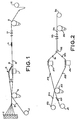
- Fig. 1 is a diagramatic view of the various devices used in carrying out one of the processes of the instant invention.
- Fig.2 is a diagramatic view of the various devices used in carrying out another version of the processes of the instant invention.
- Fig. 3 is a perspective view of the gas spreading means used in carrying out a part of the process of the instant invention.
- Fig. 4 is a perspective view of the same device with the top removed.
- The thermoplastic polymers which are useful in carrying out the invention may belong to virtually any type of relatively high molecular weight thermoplastic polymer, including polyethylene, polypropylene, polyester, the various polyamides, polyimides, polyamidimides,polyetherimides,polysulfones (e.g. polyether sulfones),polyether ether ketones, polybutylene terephthalate and the like. The melting point of the polymer should generally be at least 50° F(28°C.) and preferably at least 200°F (111°C) above ambient conditions. Higher melting temperatures ensure that there will be no undue sticking or binding of the spun fibers prior to use. In addition to one component polymer systems,mixtures of various thermoplastic polymers may also be employed to advantage where specific combinations of properties are desired.
- Of particular importance are the liquid crystal polymers or LCPs. Examples of these polymers include the wholly aromatic polyester resins which are discussed in the following publications: (a) Polyesters of Hydroxybenzoic Acids, by Russell Gilkey and John R. Caldewell, J. of Applied Polymer Sci., Vol. II, Pages 198 to 202 (1959),(b) Polyarylates (Polyesters From Aromatic Dicarboxylic Acids and Bisphenols), by G. Bier, Polymer, Vol.15, Pages 527 to 535 (August 1974), (c) Aromatic Polyester Plastics, by S.G. Cottis, Modern Plastics, Pages 62 to 63 (July 1975); and (d) Poly(p-Oxybenzoyl Systems): Homopolymer for Coatings: Copolymers for Compression and Injection Molding, by Roger S.Storm and Steven G. Cottis, Coatings Plast. Preprint.Vol. 34, No. 1, Pages 194 to 197 (April 1974). See also. U.S. Patents Nos. 3,039,994; 3,169,121; 3,321,437; 3,553,167; 3,637,595;3,651,014; 3,723,388; 3,759,870; 3,767,621;3,778,410; 3,787,370;3,790,528;3,829,406; 3,890,256; and 3,975,487.
- Other polyesters are disclosed, for instance, in (a) Polyester X7G-A Self Reinforced Thermoplastic, by W.J. Jackson, Jr., H.F. Kuhfuss, and T.F. Gray, Jr., 30th Anniversary Technical Conference, 1975 Reinforced Plastics/Composites Institute, The Society of the Plastics Industry,Inc., Section 17-D, Pages 1 to 4, (b) Belgian Patents Nos. 838,935 and 828,936, (c) Dutch Patent No. 7505551, (d) West German Patents Nos. 2520819, 2520820,27222120, 2834535,2834536 and 2834537, (e) Japanese Patents Nos. 43-223; 2132-116; and 3021-293, and (f) U.S. Patents Nos. 3,991,083; 4,991,014; 4,057,597;4,066,620; 4,067,852; 4,075,262-;4,083,829; 4,093,595; 4,112,212;4,118,372; 4,130,545; 4,130,702;4,146,702,4,153,779; 4,156,070; 4,159,365; 4,160,755;4,161,470; 4,169,933; 4,181,792;4,183,895;4,184,996; 4,188,476; 4,191,681; 4,201,856; 4,219,461; 4,224,433; 4,226,970;4,230,817; 4,232,143;4,238,598; 4,238,600; 4,239,913; 4,242,496; 4,245,082; 4,245,804;4,247,514; 4,256,624; 4,265,802; 4,267,289; 4,269,965; 4,279,803; and 4,299,756.
- The polyesters and copolyesters which are preferred consist essentially of structural units having recurring groups of the formula


- The foregoing ring systems, except for R2 as indicated below, are also intended to include one or more substituents, e.g., chloro, bromo,fluoro, or lower alkyl (1-4 carbon atoms) on the ring or rings. The R2 aromatic ring systems should preferably be unsubstituted when only one kind of unit I and one kind of unit II are used, i.e.,when a homopolymer is formed to ensure obtaining oriented fibers. In the case of copolymers, it is preferred that the R2aromatic ring systems be unsubstituted because of thermal or hydrolytic instability and/or cost of the R2-ring substituted copolymers.
- Also included are those (co)polyesters wherein up to 25 mol %, preferably up to 5 mol %, based on the total I,II and III units; are aromatic polymer-forming units (i.e., units wherein the chain extending functional groups are attached to aromatic rings not conforming to those described above and which do not interfere with the anisotropic melt forming capability of the polymers. A non-limiting list of these units includes


- The (co)polyesters, as mentioned above, may comprise units I and II in substantially equimolar amounts or may comprise unit III or may comprise a combination of units I,II, and III, and, of course, more than one kind of unit (I,II and/or III) can be present in the polymer.
- Preferred (co)polyesters for use in the invention consist essentially of units 1 and II. In such polymers, it is preferred that R1 is selected from 1,4-phenylene; chloro-, dichloro-,bromo-,dibromo-,methyl-, dimethyl-, and fluoro-1, 4-phenylene; 4,4'-biphenylene; 3,3',5,5' - tetramethyl-4,4'-biphenylene and R2 is selected from trans-1,4-cyclohexylene; trans-2,5-dimethyl-1,4-cyclohexylene; trans-vinylenebis (1,4-phenylene); 4,4'-biphenylene; 2,6-naphthylene; and 1, 4-phenylene and with the proviso that more than one kind of unit I or II are present. Of such copolyesters, two types are particularly preferred because of properties and cost.. In the first type, the polymers consist essentially of the recurring units


- A list of useful dicarboxylic acids includes, for example terephthalic acid, 4,4'-bibenzoic acid, 4,4'-oxydi- benzoic acid, 4,4'-thiodibenzoic acid, 4-carboxyphenoxyacetic acid, 4,4'-trans-stilbenedicarboxylic acid, 2,6-naphthalenedicarboxylic acid, ethyleneoxy-4,4'-dibenzoic acid, isophthalic acid, the halogen and methyl substituted derivatives of the foregoing dicarboxylic acids, 1,4-trans-cyclohexanedicarboxylic acid and 2,5-dimethyl-1,4-trans-cyclohexanedicarboxylic acid.
- A nonlimiting list of phenolic carboxylic acids includes 6-hydroxy-2-naphthoic acid, 4-hydroxy-4'carboxy azobenzene, ferulic acid, 4-hydroxybenzoic acid,4-(4'-hydroxy- phenoxy)-benzoic acid and 4-hydroxycinnamic acid and the alkyl, alkoxy and halogen substituted versions of these compounds.
- Of the (co)polyesters containing only type III units, there are preferred those which consist essentially of the recurring units

- The (co)polyesters are prepared preferably by melt polycondensation of derivatives of dihydric phenols and aromatic aliphatic,aromatic and cycloaliphatic dicarboxylic acids or their derivatives . A convenient preparative method is the melt polycondensation of the diacetate of a dihydric phenol with a dicarboxylic acid. Alternatively, phenolic carboxylic acids or their derivatives may be used as coreactants in the preparation of polyesters and copolyesters.
- A list of useful dihydric phenols, preferably used in the form of their diacetate derivatives, includes, for example hydroquinone, chloro- hydroquinone,bromohydroquinone, methylhydroquinone, dimethyl-hydroquinone, dichlorohydroquinone, dibromohydroquinone, 4,4'- oxydiphenol,4,4'-isopropylidenediphenol, 4,4'-thiodiphenol,4,4'-biphenol,3,5,3' ,5'-tetramethyl-4,4' -bisphenol, 3,5,3',5'- tetrachloro-4,4'-biphenol,2,6-dihydroxynaphthalene, 2,7-dihydroxynaphthalene, and 4,4'-methylenediphenol.
- In addition, it is possible to prepare anisotropic polymers by polymerizing methylacrycloxy benzoic acid utilizing an alkali metal hydroxide and free radical initiators as described in U.S. Patents Nos. 4,112,212,4,130,702 and 4,160,755.
- Useful phenolic-carboxylic acid derivatives include, for example p-acetoxybenzoic acid and p-acetoxy- cinnamic acid.
- A nonlimiting list of various polyesters and copolyesters includes: poly(methyl-1,4-
phenylene 2,5-dimethyl- trans- hexahydroterephthalate):copoly(methyl-1,4-phenylene trans-hexa- hydroterephthalate/terephthalate) (8/2); copoly (chloro-1,4-phenylene trans-hexahydroterephthalate/isophtha- late) (9/1) and (8/2);copoly(ethyl-1,4-phenylene terephthalate/ 2,6-naphthalate) (7/3); copoly(tert.butyl-1,4-phenylene/3,3', 5,5'-tetramethyl-4,4'-bi-phenylene/terephthalate) (7/3); copoly(chloro-l,4-phenylene/-3,3',5,5'-tetrachloro-4,4'-biphenylene terephthalate) (7/3). - The liquid crystal polymers including wholly aromatic polyesters and poly(ester-amide)s which are suitable for use in the present invention may be formed by a variety of ester forming techniques involving reacting organic monomer compounds possessing functional groups which, upon condensation, form the requisite recurring moieties.
- For instance, the functional groups of the organic monomer compounds may be carboxylic acid groups, hydroxyl groups, ester groups, acryoxy groups, acid halides, amine groups, etc. The organic monomer compounds may be reacted in the absence of a heat exchange fluid via a melt acidolysis procedure. They, accordingly may be heated initially to form a melt solution of the reactants with the reaction continuing as said polymer particles are suspended therein. A vacuum may be applied to facilitate removal of volatiles formed during the final state of the condensation (e.g., acetic acid or water).
- Our U.S. Patent No. 4,083,829, entitled "Melt Processable Thermotropic Wholly Aromatic Polyester," describes a slurry polymerization process which may be employed to form the wholly aromatic polyesters which are preferred for use in the present invention. According to such a process, the solid product is suspended in a heat exchange medium. Although that patent is directed to the preparation of wholly aromatic polyesters, the process may also be employed to form poly(ester-amide)s.
- When employing either the melt acidolysis procedure or the slurry procedure of U.S. Patent No. 4,083,829, the organic monomer reactants from which the wholly aromatic polyesters are derived may be initially provided in a modified form whereby the usual hydroxy groups of such monomers are esterified (i.e., they are provided as lower acyl esters). The lower acyl groups preferably have from two to four carbon atoms. Preferably, the acetate esters of organic monomer reactants are provided. When poly(ester-amide)s are to be formed, an amine group may be provided as a lower acyl amide.
- Representative catalysts which optionally may be employed in either the melt acidolysis procedure or in the slurry procedure of U.S. Patent No. 4,083,829 include dialkyl tin oxide (e.g. dibutyl tin oxide), diaryl tin oxide, titanium dioxide, antimony trioxide, alkoxy titanium silicates, titanium alkoxides, alkali and alkaline earth metal salts of carboxylic acids (e.g., zinc acetate), the gaseous acid catalysts such as Lewis acids (e.g. BF3), hydrogen halides (e.g. HCl), etc. The quantity of catalyst utilized typically is 0.001 tc 1 percent by weight based upon the total monomer weignt, and most commonly 0.01 to 0.2 percent by weight.
- The wholly aromatic polyesters and poly(ester-amide)s suitable for use in the present invention tend to be substantially insoluble in common polyester solvents and accordingly are not susceptible to solution processing. As discussed previously, they can be readily processed by common melt processing techniques. Most suitable wholly aromatic polymers are soluble in pentafluorophenol to a limited extent.
- The wholly aromatic polyesters which are preferred for use in the present invention commonly exhibit a weight average molecular weight of 2,000 to 200,000 and preferably 10,000 to 50,000, and most preferably 20,000 to 25,000. The wholly aromatic poly(ester-amides which are preferred for use in the present invention commonly exhibit a molecular weight of 5,000 to 50,000, and preferably 10,000 to 30,000; e.g., 15,000 to 17,000. Such molecular weight may be determined by gel permeation chromatography and other standard techniques not involving the dissolving of the polymer, e.g., by end group determination via infrared spectroscopy on compression molded films. Alternatively, light scattering techniques in a pentafluorophenol solution may be employed to determine the molecular weight.
- The wholly aromatic polyesters and poly(ester-amide)s additionally commonly exhibit an inherent viscosity(I.V.) of at least 2.0 dl./g.,e.g.,2.0 to 10.0 dl./g., when dissolved at a concentration of 0.1 percent by weight in pentafluorophenol at 60°C.
- For the purposes of the present invention, the aromatic rings which are included in the polymer backbones of the polymer components may include substitution of at least some of the hydrogen atoms present upon an aromatic ring. Such substituents include alkyl groups of up to four carbon atoms; alkoxy groups having up to four carbon atoms; halogens;and additional aromatic rings, such as phenyl and substituted phenyl. Preferred halogens include fluorine, chlorine and bromine. Although bromine: atoms tend to be released from organic compounds at high temperatures, bromine is more stable on aromatic rings than on aliphatic chains, and therefore is suitable for inclusion as a possible substituent on the aromatic rings.
- The fibers useful herein are basically carbon fibers which may be prepared by a variety of methods. Virtually any of the prior art methods of carbon fiber preparation may be employed in this invention.
- The preparation of carbon fibers has been well known in the art for many years. Basically, there are two methods for preparing these fibers, which differ with respect to the starting materials employed. One method starts with a natural or synthetic fiber, which is then carbonized. In the other process petroleum pitch or coal tar pitch is used as the starting material.
- Typical of the patents involving the use of pitch is U.S. Patent No. 4,317,809. Generally, using the pitch process, the pitch is heated under high pressure and then under atmospheric pressure with sparging to form a mesophase pitch. Following this step, the pitch is converted into a fiber, thermoset, and carbonized.
- Included among the fibers which may be formed into graphite or carbon fibers and are useful in this invention are those materials where the polymeric precursor is, for example, cellulose, acrylic derivatives, and, in particular, polyacrylonitriles. Specifically, the acrylic polymer may contain not less than 85 mol percent of acrylonitrile units, with not more than 15 mol percent of a monovinyl compound which is copolymerizable with acrylonitrile, such as styrene, methylacrylate, methylmethacrylate,vinyl acetate, vinyl chloride, vinylidene chloride or vinyl pyridine. Other copolymerizable monomers include styrene sulfonic acid,allyl sulfonic acid, alkyl acrylates and methacrylates, vinyl acetate, vinyl proprionate, vinyl chlorine and vinylidine chloride.
- There-are numerous procedures for carbonizing the precursor fibers. In general, they involve a first heating step in the range of 200-400°C.,followed by a second heating step in a non-oxidizing atmosphere at temperatures ranging from 800-3000°C. For examples of these processes, see U.S. Patents Nos. 4,197,282; 4,079,122; and 4,131,644.
- The carbon fibers which are particularly useful herein have bundle or tow deniers in the range of from 300-100,000 and filament counts of from 300-300,000, preferably deniers of 1,000-16,000 and filament counts of 3,000 -24,000. : The fibers also should exhibit a tensile strength of at least 100,000 psi (689 000 kPa) and a tensile modulus of 10 to 120 x 106 psi (68.9 to 826.8 x 10⁶ kPa).
- The thermoplastic fibers which are particularly useful herein have bundle cross-sectional areas ranging from twice that of the carbon fiber tows to half that of the carbon fiber tow. Bundle or tow denier will generally be in the range of 1 to 50 and the fiber count will depend upon single filament denier (higher counts are required with lower denier filaments). However, in general, from 10 to 150,000 filaments, preferably 100 to 10,000 filaments, are employed. The modulus of the fiber should be in the range of 50,000 to 500,000 psi (344,500 to 3,445,000 kPa). The thermoplastic fiber should also exhibit a melting point of at least 50° F (28°C), preferably at least 200°F (111°C), above ambient termperatures. And of course, the fiber should melt and fuse at temperatures no higher than 1,0000F (538°C), preferably no higher than 800°F (427°C), in order to be useful herein.
- The weight ratio of the two fibers which are intermixed can vary widely. However, in order to prepare satisfactory composites, it is necessary that sufficient thermoplastic polymer fiber be employed to obtain complete wetting of the carbon fibers. Generally, no less than 30 percent,by volume, of the thermoplastic polymer fibers may be employed. The maximum amount of thermoplastic polymer depends upon the strength properties which are required. In general, when less than ten percent, by volume, of the carbon fiber is present, the-resulting composite products have strength and stiffness properties which are poor in relation to products containing higher amounts of carbon fibers. Preferably 20 to 60 percent, by volume, of the carbon fiber material should be present in the combined tow.
- In addition to the carbon fiber and the thermoplastic fibers which are used herein, it is possible to add to the fiber blends of the invention other non-thermoplastic fibers as reinforcing fibers. Examples of these materials include the various types of fiberglasses and ceramic fibers.
- In the event additional reinforcing fibers are added, it is possible to reduce the amount of the carbon fiber which is used to as low as 10 volume percent. However, the maximum combined amount of the added reinforcing fiber plus the amount of the carbon fiber which is employed should not exceed the upper limit specified above for the carbon fiber alone.
- In Figure 1 of the drawings, a carbon fiber tow (1) is obtained having the properties specified above. The fibers from the carbon fiber tow are passed through a fiber guide (3) and onto a first Godet roll (4). The first Godet roll is synchronized with a second Godet roll (11) at rates of speed such that the second Godet roll revolves slightly slower than the first Godet roll. Hence, the fibers between the two Godet rolls, which are subsequently spread and intermixed during the process of the invention, remains in a low tensioned (approaching tension-free) state which provides for effective fiber intermixing. Individual thermoplastic polymer fibers, such as polybutylene terephthalate fibers, are mounted on a bobbin rack (2) and the fibers are fed through a fiber guide (3) onto the first Godet roll (4). A tension comb may be employed after the fibers leave the bobbin and before they are brought into contact with the Godet roll. This tension comb serves to improve the contact of the fiber with the Godet roll and to increase the width of the fiber tow.
- At this point in the process neither the carbon fibers nor the thermoplastic fibers are intermixed or are in contact. Rather, both are wrapped separately around the first Godet roll (4) to provide tension control. After leaving the Godet roll, the individual fibers separately pass through a fiber guide (5) to maintain directional control. After leaving the fiber guide (5), the thermoplastic polymer fibers pass through a fiber comb (6).
- The fiber comb having a plurality of spaced-apart fingers acts to maintain as separate the various fine yarns of the thermoplastic polymeric fiber so as to preserve separation of the individual fibers. The carbon fibers, on the other hand, after heaving the fiber guide (5), are directed into a gas banding jet (7).
- The gas banding jet shown in Figs 3 and 4 is used to uniformly spread the fiber tows. A gas "banding" jet can also be used as an intermixing means whereby the gas jet serves to uniformly intermix the two fiber tows. The banding jet consists of a gas box (40) into which compressed air or another gas is fed through a conventional adjustable gas metering means (41). The preferred pressure of gas flow into the gas jet is in the range of 0.5 to 10 psi (3.45 to 68.9 kPa). One,or more than one, gas exit ports (44) are provided to cause gas from within the gas box to impinge in a generally perpendicular fashion upon the fiber tow which passes across the exit ports. Preferably the exit ports are V-shaped and pointed in the direction of movement of the fiber tow across the box.
- As shown in Fig.4, the gas banding jet is provided with shims (46) or other means to allow a gas box cover (48) to be attached, so that a flow channel for the fibers is provided. The gas box cover is held in place by convenient attachment means, such as clamps (49).
- In an alternative process shown in Fig.2 both the thermoplastic fiber and the carbon fiber are subject to gas banding jet treatment (26) and (27). However, particularly with lower molecule weight, less high melting-polymers, such as polybutylene terephthalate, a fiber comb having a plurality of spaced-apart fingers, as described above, may be employed in place of the banding jet.
- After th.e fibers are spread by banding jets or banding jets in combination with combs, they are intermixed using an intermixing means (8). In Fig.1 the intermixing means is a pair of stationary rods or bars. The fibers from the spread carbon fiber tow and the fibers from the spread thermoplastic tow or yarns both initially come into contact together on the bottom of the first stationary rod or bar. The fibers then are deflected across the top of the second stationary bar or rod and, as a result, are intermixed. In order to ensure complete intermixing, it is necessary that both fibers be uniformly spread across their entire width and that the area within which both fibers are spread be virtually identical. Finally, it is necessary that intermixing be undertaken in a relatively tension-free state. If high tension is imparted to either of the fiber tows,full (or optimal) intermixing may not occur. After passing over and under the stationary bars, the combined fiber tow may be further intermixed using an air entanglement jet as described above.
- After intermixing, the fibers pass through a comb (9) to maintain dimensional stability ahd-through twist guides (10) to impart a slight twist to the intermixed fibers. The twist is imparted in order to maintain the intermixing of the fibers. Instead of using an actual half-twist, false-twisting of the fibers using methods well known in the art may be employed. In the alternative, a fiber wrap may be used to hold the intermixed fibers together. The overwrap may be of any convenient type of fiber. However, it is preferred that the overwrap consist of a relatively small quantity of thermoplastic fibers.
- The mixed fibers are then wrapped around a second Godet roll (11) which, as pointed out above, serves in con- juncticn with the first Godet roll to provide a relatively tension-free zone to allow fiber intermixing. The fibers are then taken up by a takeup roll (12) for storage. Of course, it is possible to impart false-twisting or actual twis;_ -.g or to wrap the fiber tow with another fiber either before or after the Godet roll. In addition, the intermixed fibers may be made stable by application of an appropriate fiber finish which serves to hold the intermixed fibers together and enable easier handling in subsequent operations, such as weaving.
- Fig. 2 is similar to Fig.1 but is the process most preferred when a liquid crystal type polymer or other higher melting point polymer is used. In Fig. 2 a carbon fiber roll (21) feeds carbon fiber through tension comb (22) and onto Godet roll (25). Liquid crystal fibers from a roll (23) are fed through a guide (24) and onto the same Godet roll (25). Separation is maintained between both fibers on the Godet roll. As pointed out above, the first Godet roll (25), when used in combination with the optional second Godet roll (35), serves to maintain the fibers in a relatively tension-free state during the intermixing process. High tension during intermixing must be avoided to assure that complete intermixing occurs.
- After the carbon fibers and the liquid crystal fibers leave the first Godet roll they are both fed into gas banding jets (26) and (27) through guides (28) and (29), respectively. In the gas banding jet the'fibers are spread to a uniform width. The fibers then pass through a second set of fiber guides (30) and (31) and are intermixed using the stationary, longitudinally extended bars shown at (32). In general, intermixing occurs as the thermoplastic bundle is fed onto the same bar in the same area as is the carbon fiber. At this point in the processing, the width of both tows is the same, and as they are brought simultaneously into contact with the same area of the bar, intimate intermixing occurs. In an alternative intermixing process, the two fiber tows are fed simultaneously into a gas jet or other gaseous intermixing device in a relatively tension-free state. In addition, the fibers may be fed into a gas jet for further intermixing after they have been treated on the stationary bars. In the gas intermixing means a jet of air impinges on the fibers, preferably perpendicular to their direction of flow.
- Following intermixing, the fibers are fed through twist guides (33) to add at least a half-twist per yard to the fiber to ensure dimensional stability. Fibers then pass through a guide (34) onto a second Godet roll (35) and from there onto a take-up roll (36).
- In use,the intermixed fibers may be filament wound, or otherwise assembled and placed on a mold, and heated under pressure to the flow temperature of the thermoplastic polymer to form composite articles which are useful in a variety of end uses where high strength,high stiffness and low weight are essential. For example, the composites formed from products prepared according to this invention may be used in forming spacecraft, airplane or automobile structural components. In addition, the carbon fiber blends of the instant invention find particular utility in those end uses where complex, three-dimensional shapes are involved. As pointed out above, the compositions of the instant invention are particularly useful where there is a small radius of curvature requiring substantial bending and shaping of the compositions of the instant invention. The .only limiting factor in forming carbon fiber shaped articles using the compositions of the instant invention is the "bendability" of the carbon fiber itself. Therefore, utilizing the compositions of the invention, it is possible to prepare materials having a minimum radius of curvature of 0.002 in.(0.05 mm), preferably as low as 0.003 in.(0.08 mm). However, with prior art thermoplastic tapes, the minimum radius of curvature is about 0.005 in. (0.13 mm). (Even then fiber directionality or alignment is distorted.) As structural elements formed from the fiber tows of this invention are heated under pressure above the melting point of the thermoplastic fiber, these fibers melt and fuse the carbon fibers together forming a consolidated composite product containing well-dispersed reinforcing fibers. Using the fiber blends of the instant invention, it is possible to prepare recreational articles, such as tennis racquet frames, racquetball racquet frames, hockey sticks, ski poles, fishing rods and golf club shafts.
- The fibers of the invention find particular utility in filament winding applications. As pointed out above, in the prior art it was extremely difficult to prepare composite articles utilizing the prior art fiber tapes. These tapes, which are prepared on an extremely large scale, are difficult to handle on a small scale, and it is particularly difficult to form them into intricately shaped articles. while the prior art employed the filament winding process with success, this process was limited to use of carbon fibers in combination with thermosetting resins if long, thin rods were to be prepared. In the prior art process, the graphite was wound onto a mold after applying a thermosetting coating or coated with the thermosetting material after winding. As a result, however, it was often difficult for the thermosetting material actually to penetrate and/or achieve good wetting of closely wound products.
- Utilizing the process of the invention in a modified filament winding procedure, it is possible to prepare intricately shaped articles when the fiber blends are oriented in directions not parallel to the long axis of the article, utilizing thermoplastic polymers in conjunction with carbon fiber reinforcements. This modified filament winding process 'begins with the use of the intermixed tows of the invention. These tows may be fed directly to a filament winder. As the filament winder moves around or up and down the mandrel or form, the carbon fiber/thermoplastic fiber tow is applied directly to the mold and heated using a radiant heater or other suitable means for immediately melting and fusing the thermoplastic polymeric fibers within the carbon fiber tow. In other words, the carbon fiber/ thermoplastic fiber tow should be heated under pressure as soon as or soon after it meets the mandrel. After full melting and resolidification occurs, the mandrel either may be dissolved using a suitable solvent, may be pulled from the product, or the mandrel may actually become a part of the product.
- Another unique use for the fiber blends prepared according to the invention is in forming woven fabrics utilizing standard techniques. According to this process, the tow of the instant invention is used either alone or in combination with other tows or fibers to form a woven mat.
- The woven fabrics prepared according to tne process of this invention may be applied to the desired mold or otherwise used in forming a composite. The previous method of choice of forming such materials involved laying down a layer of graphite, followed by a layer of thermoplastic film, followed by another layer of graphite, etc. Now the materials can be combined in a solid woven layer and much more readily applied to a mold. After the composite is formed, it is then heated under pressure above the flow point of the thermoplastic polymer, and a composite having good mechanical strength and stiffness properties results. The strength and stiffness enhancement can occur in one or more directions i.e., those directions along which carbon fiber is aligned parallel to the defining vector.
- A liquid crystal polymeric (LCP) fiber tow based upon a copolymer prepared from 6-hydroxy-2 napthoic acid and p-hydroxy benzoic acid was obtained. The LCP had a density of 1.4 g/cc, and the tow itself was formed of 660 filaments (2.25 denier per filament). The tow had an initial modulus of 5670 gms, a tenacity of 10.5 g/denier, and an elongation of 2%. the second fiber to be used for intermixing with the LCP fiber was Celion 3000 carbon fiber (3000 filament count), having a density of 1.7 g/cc, a tensile strength of 515 xl03 psi (354835 x 103 kPa), a tensile modulus of 34 x 106 psi (234 x 106 kPa) and an ultimate elongation of 1.5%. The carbon fiber is produced from a polyacrylonitrile precursor and is available from Celanese Specialty Operations,Hercules and Union Carbide.
- Bobbins containing the LCP polymeric fiber tow and the Celion fiber tow were spaced apart on a bobbin rack. Fibers from both bobbins were fed onto and separately wrapped around a Godet roll, so that upon mixing the mixed tow would contain approximately 50% by volume of liquid crystal polymer and approximately 50% by volume of carbon fiber. The LCP polymeric fiber was subject to a 50 gram weight on a tensioning device prior to being wrapped around the Godet roll, in order to maintain smooth tracking on the roll. After leaving the Godet roll, both fibers were separately subjected to air jet banding treatments utilizing an air jet which impinged air approximately perpendicular to the fiber through V-shaped nozzles. The jet for the liquid crystal polymer was operated at 5 psi (34.45 kPa), while the carbon fiber jet was operated at 4.psi (27.56 kPa). After leaving the banding jets, the fibers were brought together over the top and underneath of two parallel, longitudinally extended, staggered stationary bars and fed through fiber guides into an entanglement jet, which was similar in design to the gas banding jet and operated at a gas pressure of 7 psi (48.23 kPa). Following intimate intermixing of the two tows, the fibers were taken up on a takeup roll at a takeup speed of 7-8 m/ min.
- Test composite panels (3.5"x 10")(90 x 250 mm) were prepared using 25 layers of the intermixed fiber tow. Each layer was prepared by first wrapping a heated drum with a Kapton film and then filament winding parallel rows of the fiber blend prepared above onto the Kapton wrapped drum.
- A layer of Kapton film was then placed over the drum, and the entire wrapped drum was heated so as to temporarily fuse the fibers together. The composite containing the 25 fused 0 layers were placed in a pressure mold, heated to 312 to 315 C. and held at this temperature for five minutes without application of significant mold pressure. The mold pressure was then increased to 500 psi (3445 kPa) at 315°C. and held under temperature and pressure for thirty minutes. The material was then cooled to 70°C. and removed from the mold. The resulting material contained 51.4% by volume of carbon fiber and had a panel thickness of 0.1027" (2.61 mm).
- Utilizing the same process , an eight ply 3.5"x 10" composite panel was prepared having a carbon fiber volume of 60.3%, a panel thickness of 0.035"(0.89 mm). The composites were evaluated for tensile, flexural and compression properties with the following results :

- Utilizing the same carbon fiber as described in Example 1, an approximate 50% by volume polybutylene terephthalate (PBT)/carbon fiber blend was prepared. The polybutylene terephthalate material had a density of 1.34 g/cc and a denier of 1520 g/9000m. The polybutylene terephthalate had a draw ratio of 2.25-1, an initial'modulus of 24 g, a tenacity of 5.3 g/denier, an elongation of 28%, a melting point of 227° C. and a denier per filament of 2.7. Seventeen packages of 33 filament count yarn were employed on a creel, and all packages were merged into a single polybutylene terephthalate fiber tow on a Godet roll. Maintained separately, but on the same Godet roll, was one package of 3000 filament count carbon fiber to provide a total approximate blend of 50/50 by volume carbon fiber/PBT.
- The polybutylene terephthalate tow was fed through a fiber comb having approximately 30 teeth, while the carbon fiber tow was fed through a gas banding jet operating as described in Example 1, at a pressure of about 2.5 to 3.5 psi (17.23 to 24.12 kPa). The two tows were then intermixed over and under parallel extended rods by feeding both tows into the same area on the bars. Intermixing was aided by the use of a second gas banding jet of the type described in Example 1, operating at 2.5 to 3.5 psi (17.23 to 24.12 kPa). After leaving the banding jet, the fibers were fed through a second fiber comb which was arranged parallel to the direction of flow of the fiber,so as to provide a tensioning path to aid in intermixing. After leaving the comb, the fibers were fed through twist guides to provide approximately half a twist per yard, (per 0.9 m), so as to maintain the fibers in their intermixed state. The fibers were then wrapped around a second Godet roll and taken up at a speed of 7-8 m/min. In order to minimize tension during the intermixing process, the second Godet roll was operated at a slightly slower speed than the first Godet roll.
- 3.5" x 10" (90 x 250 mm) panel composites were prepared generally as described in Example 1 and evaluated with the results as shown in the attached table. Differences in processing conditions are noted in Table II.
- A sample of the PBT/carbon fiber blend prepared above was wrapped with a 100 denier polybutylene terephthalate yarn as described above at four wraps per in.(per 2.5 cm) to form a compact yarn suitable for fabric weaving. The PBT fabric wrap was chosen, so that it would form a part of the matrix upon composite fabrication. The resulting wrapped yarn was then divided into 96 different yarn segments and placed on spools mounted on a special creel. A 6" (152 mm) wide fabric was then woven on a modified Draper XD loom, using a plain weave pattern. The resulting woven product had dimensions of 16 ends per inch (per 25.4 mm) x 15 picks per inch (per 25.4 mm) and weighed 16 oz./yd2(542 g/m2).

- An approximate 50/50% by volume blend was prepared based upon the carbon fiber described in Example 1 and a polyether ether ketone (PEEK) thermoplastic polymer. The fiber prepared from the PEEK had a density of 1.3 g/cc, a melting point of 338° C., an initial modulus of 53 grams,a tenacity of 2.7 g/denier, an elongation of 63%, and in 10 filaments per package tows a dpf of 367 (g/9000m). Four (10 filaments per package) tows were placed on a creel and the fibers were blended together on a Godet roll, but maintained separately from the carbon fiber which was also wrapped around the Godet roll. The PEEK fiber was then directed through a fiber comb as described in Example 2 and into a gas banding jet. The carbon fiber after leaving the Godet roll also entered a gas banding jet. Both jets were operating at a pressure of about 3 psi (20.7 kPa). After leaving the jets the fibers were intermixed above and below two parallel, longitudinally extended rods and fed through a second parallel fiber comb, twisted to maintain dimensional stability, fed over a second Godet roll and taken up at a speed of 7-10 m/min. A satisfactory composition resulted.
Claims (18)
Applications Claiming Priority (6)
| Application Number | Priority Date | Filing Date | Title |
|---|---|---|---|
| US58982584A | 1984-03-15 | 1984-03-15 | |
| US58982384A | 1984-03-15 | 1984-03-15 | |
| US58981784A | 1984-03-15 | 1984-03-15 | |
| US589823 | 1984-03-15 | ||
| US589817 | 1990-09-27 | ||
| US589825 | 1996-01-22 |
Publications (2)
| Publication Number | Publication Date |
|---|---|
| EP0156599A1 true EP0156599A1 (en) | 1985-10-02 |
| EP0156599B1 EP0156599B1 (en) | 1988-11-09 |
Family
ID=27416554
Family Applications (1)
| Application Number | Title | Priority Date | Filing Date |
|---|---|---|---|
| EP85301791A Expired EP0156599B1 (en) | 1984-03-15 | 1985-03-14 | Composite carbon fibre and thermoplastic fiber blends |
Country Status (3)
| Country | Link |
|---|---|
| EP (1) | EP0156599B1 (en) |
| CA (1) | CA1293367C (en) |
| DE (1) | DE3566128D1 (en) |
Cited By (18)
| Publication number | Priority date | Publication date | Assignee | Title |
|---|---|---|---|---|
| GB2183540B (en) * | 1985-12-10 | 1990-01-31 | Christopher Francis Coles | Improvements in or related to fibres |
| EP0401518A2 (en) * | 1989-05-18 | 1990-12-12 | BASF Aktiengesellschaft | Seals and bearings of fibre-reinforced plastics |
| EP0405261A2 (en) * | 1989-06-26 | 1991-01-02 | BASF Aktiengesellschaft | Single diaphragm forming of drapeable resin impregnated composite materials |
| US5076872A (en) * | 1985-12-09 | 1991-12-31 | Fuji Standard Research, Inc. | Process for preparing a flexible composite material |
| EP0486884A1 (en) * | 1990-11-20 | 1992-05-27 | Cytec Technology Corp. | Method for making hybrid yarn |
| EP0504445A1 (en) * | 1987-03-03 | 1992-09-23 | Concordia Mfg. Co., Inc. | Apparatus and method for commingling continuous multifilament yarns |
| EP0542070A1 (en) * | 1991-11-14 | 1993-05-19 | Cytec Technology Corp. | Hybrid yarn made of polyamide fibres and reinforcing fibres |
| EP0555666A1 (en) * | 1992-01-29 | 1993-08-18 | Cytec Technology Corp. | Method of manufacture of a tennis racket frame |
| US5380477A (en) * | 1993-05-25 | 1995-01-10 | Basf Corporation | Process of making fiber reinforced laminates |
| EP0717133A2 (en) | 1994-12-16 | 1996-06-19 | Hoechst Aktiengesellschaft | Production and application of a shrinkable and shrinked, permanently deformable textil material made out of hybrid yarn |
| US5792555A (en) * | 1995-04-10 | 1998-08-11 | Hoechst Aktiengesellschaft | Hybrid yarn and permanent deformation capable textile material produced therefrom, its production and use |
| US6292954B1 (en) | 1998-11-02 | 2001-09-25 | O'bradaigh Conchur | Protective headgear |
| FR2811688A1 (en) * | 2000-07-13 | 2002-01-18 | Schappe Sa | UNIDIRECTIONAL TABLECLOTH IN COMPOSITE MATERIAL |
| US6820406B2 (en) | 2001-05-14 | 2004-11-23 | Cargill, Incorporated | Hybrid yarns which include plant bast fiber and thermoplastic fiber, reinforcement fabrics made with such yarns and thermoformable composites made with such yarns and reinforcement fabrics |
| US6833399B2 (en) | 2001-09-21 | 2004-12-21 | Cargill, Limited | Flowable flax bast fiber and flax shive blend useful as reinforcing agent |
| US7344667B2 (en) | 2002-04-23 | 2008-03-18 | Toray Industries, Inc. | Prepreg, production process thereof, and molded article |
| DE102009029437B4 (en) * | 2008-09-16 | 2014-11-13 | Technische Universität Dresden | Mixed yarn generator and method for producing mixed yarn |
| EP2966204A4 (en) * | 2013-03-06 | 2017-02-01 | Mitsubishi Gas Chemical Company, Inc. | Combined filamanet yarn, woven and knitted fabric, composite material, and process for manufacturing composite material |
Families Citing this family (1)
| Publication number | Priority date | Publication date | Assignee | Title |
|---|---|---|---|---|
| DE102020105167A1 (en) | 2020-02-27 | 2021-09-02 | Thüringisches Institut für Textil- und Kunststoff-Forschung e. V. Rudolstadt | Method for producing a hybrid yarn |
Citations (7)
| Publication number | Priority date | Publication date | Assignee | Title |
|---|---|---|---|---|
| FR2124919A5 (en) * | 1971-01-29 | 1972-09-22 | Coats J Et P Ltd | Textile structure - formed by introducing thermoplastic yarn and heating to bond the other components |
| US3978267A (en) * | 1970-05-20 | 1976-08-31 | Imperial Chemical Industries Limited | Compact twistless textile yarn comprising discontinuous fiber bonded by potentially adhesive composite fibers |
| US4051660A (en) * | 1974-07-15 | 1977-10-04 | Akzona Incorported | Yarns and their method of manufacture |
| US4084399A (en) * | 1976-03-31 | 1978-04-18 | Nippon Carbon Kabushiki Kaisha | Gut for racket |
| US4159618A (en) * | 1978-03-13 | 1979-07-03 | Albany International Corp. | Composite yarn |
| FR2446336A1 (en) * | 1979-01-10 | 1980-08-08 | Payen & Cie L | NOVEL TYPE OF GUIP TEXTILE YARN AND METHOD FOR OBTAINING SAME |
| BE894875A (en) * | 1982-10-29 | 1983-02-14 | Luxilon Ind Co | Room temp. hardening thermoplastic textile material - comprising textile and glass fibres with monofilaments or tapes of crystalline polyester |
-
1985
- 1985-03-14 EP EP85301791A patent/EP0156599B1/en not_active Expired
- 1985-03-14 DE DE8585301791T patent/DE3566128D1/en not_active Expired
- 1985-03-14 CA CA000476472A patent/CA1293367C/en not_active Expired - Fee Related
Patent Citations (7)
| Publication number | Priority date | Publication date | Assignee | Title |
|---|---|---|---|---|
| US3978267A (en) * | 1970-05-20 | 1976-08-31 | Imperial Chemical Industries Limited | Compact twistless textile yarn comprising discontinuous fiber bonded by potentially adhesive composite fibers |
| FR2124919A5 (en) * | 1971-01-29 | 1972-09-22 | Coats J Et P Ltd | Textile structure - formed by introducing thermoplastic yarn and heating to bond the other components |
| US4051660A (en) * | 1974-07-15 | 1977-10-04 | Akzona Incorported | Yarns and their method of manufacture |
| US4084399A (en) * | 1976-03-31 | 1978-04-18 | Nippon Carbon Kabushiki Kaisha | Gut for racket |
| US4159618A (en) * | 1978-03-13 | 1979-07-03 | Albany International Corp. | Composite yarn |
| FR2446336A1 (en) * | 1979-01-10 | 1980-08-08 | Payen & Cie L | NOVEL TYPE OF GUIP TEXTILE YARN AND METHOD FOR OBTAINING SAME |
| BE894875A (en) * | 1982-10-29 | 1983-02-14 | Luxilon Ind Co | Room temp. hardening thermoplastic textile material - comprising textile and glass fibres with monofilaments or tapes of crystalline polyester |
Cited By (26)
| Publication number | Priority date | Publication date | Assignee | Title |
|---|---|---|---|---|
| US5076872A (en) * | 1985-12-09 | 1991-12-31 | Fuji Standard Research, Inc. | Process for preparing a flexible composite material |
| GB2183540B (en) * | 1985-12-10 | 1990-01-31 | Christopher Francis Coles | Improvements in or related to fibres |
| EP0504445A1 (en) * | 1987-03-03 | 1992-09-23 | Concordia Mfg. Co., Inc. | Apparatus and method for commingling continuous multifilament yarns |
| EP0401518A3 (en) * | 1989-05-18 | 1992-06-24 | BASF Aktiengesellschaft | Seals and bearings of fibre-reinforced plastics |
| EP0401518A2 (en) * | 1989-05-18 | 1990-12-12 | BASF Aktiengesellschaft | Seals and bearings of fibre-reinforced plastics |
| EP0405261A3 (en) * | 1989-06-26 | 1992-03-18 | Basf Aktiengesellschaft | Single diaphragm forming of drapeable resin impregnated composite materials |
| EP0405261A2 (en) * | 1989-06-26 | 1991-01-02 | BASF Aktiengesellschaft | Single diaphragm forming of drapeable resin impregnated composite materials |
| EP0486884A1 (en) * | 1990-11-20 | 1992-05-27 | Cytec Technology Corp. | Method for making hybrid yarn |
| EP0542070A1 (en) * | 1991-11-14 | 1993-05-19 | Cytec Technology Corp. | Hybrid yarn made of polyamide fibres and reinforcing fibres |
| US5464684A (en) * | 1991-11-14 | 1995-11-07 | Cytec Technology Corp. | Hybrid yarn comprising a core of intermixed polyamide filaments and reinforcing rilaments wherein the core is wrapped by a polyamide fiber |
| EP0763372A3 (en) * | 1992-01-29 | 1997-03-26 | Cytec Technology Corp. | Tennis racket frame |
| EP0555666A1 (en) * | 1992-01-29 | 1993-08-18 | Cytec Technology Corp. | Method of manufacture of a tennis racket frame |
| EP0763372A2 (en) | 1992-01-29 | 1997-03-19 | Cytec Technology Corp. | Tennis racket frame |
| US5380477A (en) * | 1993-05-25 | 1995-01-10 | Basf Corporation | Process of making fiber reinforced laminates |
| EP0717133A2 (en) | 1994-12-16 | 1996-06-19 | Hoechst Aktiengesellschaft | Production and application of a shrinkable and shrinked, permanently deformable textil material made out of hybrid yarn |
| US5688594A (en) * | 1994-12-16 | 1997-11-18 | Hoechst Aktiengesellschaft | Hybrid yarn |
| US5792555A (en) * | 1995-04-10 | 1998-08-11 | Hoechst Aktiengesellschaft | Hybrid yarn and permanent deformation capable textile material produced therefrom, its production and use |
| US6292954B1 (en) | 1998-11-02 | 2001-09-25 | O'bradaigh Conchur | Protective headgear |
| FR2811688A1 (en) * | 2000-07-13 | 2002-01-18 | Schappe Sa | UNIDIRECTIONAL TABLECLOTH IN COMPOSITE MATERIAL |
| WO2002006036A1 (en) * | 2000-07-13 | 2002-01-24 | Sa Schappe | Unidirectional web made of composite material |
| US7387828B2 (en) | 2000-07-13 | 2008-06-17 | Sa Schappe | Unidirectional sheet made of a composite |
| US6820406B2 (en) | 2001-05-14 | 2004-11-23 | Cargill, Incorporated | Hybrid yarns which include plant bast fiber and thermoplastic fiber, reinforcement fabrics made with such yarns and thermoformable composites made with such yarns and reinforcement fabrics |
| US6833399B2 (en) | 2001-09-21 | 2004-12-21 | Cargill, Limited | Flowable flax bast fiber and flax shive blend useful as reinforcing agent |
| US7344667B2 (en) | 2002-04-23 | 2008-03-18 | Toray Industries, Inc. | Prepreg, production process thereof, and molded article |
| DE102009029437B4 (en) * | 2008-09-16 | 2014-11-13 | Technische Universität Dresden | Mixed yarn generator and method for producing mixed yarn |
| EP2966204A4 (en) * | 2013-03-06 | 2017-02-01 | Mitsubishi Gas Chemical Company, Inc. | Combined filamanet yarn, woven and knitted fabric, composite material, and process for manufacturing composite material |
Also Published As
| Publication number | Publication date |
|---|---|
| CA1293367C (en) | 1991-12-24 |
| EP0156599B1 (en) | 1988-11-09 |
| DE3566128D1 (en) | 1988-12-15 |
Similar Documents
| Publication | Publication Date | Title |
|---|---|---|
| US4871491A (en) | Process for preparing composite articles from composite fiber blends | |
| US4874563A (en) | Process for preparing tows from composite fiber blends | |
| US6045906A (en) | Continuous, linearly intermixed fiber tows and composite molded article thereform | |
| US4818318A (en) | Method of forming composite fiber blends | |
| US4799985A (en) | Method of forming composite fiber blends and molding same | |
| EP0156599B1 (en) | Composite carbon fibre and thermoplastic fiber blends | |
| EP0351201A2 (en) | Non-shrinkable hybrid yarn | |
| US4588538A (en) | Process for preparing tapes from thermoplastic polymers and carbon fibers | |
| EP0156600B1 (en) | Composite fiber blends | |
| US5688594A (en) | Hybrid yarn | |
| US5989710A (en) | Molding material for thermoplastic composites | |
| US4770926A (en) | Hybrid fiber-reinforced plastic composite material | |
| AU711934B2 (en) | Hybrid yarn and permanent deformation capable textile material produced therefrom, its production and use | |
| US11141949B2 (en) | Methods of producing thermoplastic composites using fabric-based thermoplastic prepregs | |
| JPS62135537A (en) | Flexible composite material and production thereof | |
| AU592736B2 (en) | Composites of stretch broken aligned fibers of carbon and glass reinforced resin | |
| JPH0536525B2 (en) | ||
| KR940007101B1 (en) | Fabric made from flat thermoplastic melt impregnated tow | |
| JPS60209034A (en) | Composite fiber blend | |
| EP0630735A2 (en) | Reinforcing composite items with composite thermoplastic staple fibers | |
| JP2876028B2 (en) | Unidirectional preform sheet and method of manufacturing the same | |
| McMahon et al. | Process for preparing composite articles from composite fiber blends | |
| CA1280344C (en) | Process for preparing tapes from thermoplastic polymers and carbonfibers | |
| JPH04183729A (en) | Molding material for thermoplastic composite | |
| KR102311409B1 (en) | Method and apparatus for impregnating resin |
Legal Events
| Date | Code | Title | Description |
|---|---|---|---|
| PUAI | Public reference made under article 153(3) epc to a published international application that has entered the european phase |
Free format text: ORIGINAL CODE: 0009012 |
|
| AK | Designated contracting states |
Designated state(s): BE DE FR GB IT NL |
|
| RIN1 | Information on inventor provided before grant (corrected) |
Inventor name: YING, LINCOLN Inventor name: CHUNG, TAI-SHUNG Inventor name: MCMAHON, PAUL E. |
|
| 17P | Request for examination filed |
Effective date: 19860402 |
|
| RAP1 | Party data changed (applicant data changed or rights of an application transferred) |
Owner name: BASF STRUCTURAL MATERIALS, INC. |
|
| 17Q | First examination report despatched |
Effective date: 19871211 |
|
| GRAA | (expected) grant |
Free format text: ORIGINAL CODE: 0009210 |
|
| AK | Designated contracting states |
Kind code of ref document: B1 Designated state(s): BE DE FR GB IT NL |
|
| REF | Corresponds to: |
Ref document number: 3566128 Country of ref document: DE Date of ref document: 19881215 |
|
| PLBI | Opposition filed |
Free format text: ORIGINAL CODE: 0009260 |
|
| ET | Fr: translation filed | ||
| 26 | Opposition filed |
Opponent name: AKZO N.V. Effective date: 19890220 |
|
| ITF | It: translation for a ep patent filed |
Owner name: RIA.NE IN TERMINE PROVV. DEL 24.7.89;ING. C. GREGO |
|
| NLR1 | Nl: opposition has been filed with the epo |
Opponent name: AKZO N.V. |
|
| PLBI | Opposition filed |
Free format text: ORIGINAL CODE: 0009260 |
|
| 26 | Opposition filed |
Opponent name: CIBA-GEIGY AG Effective date: 19890629 Opponent name: AKZO N.V. Effective date: 19890220 |
|
| NLR1 | Nl: opposition has been filed with the epo |
Opponent name: CIBA-GEIGY AG |
|
| PLBI | Opposition filed |
Free format text: ORIGINAL CODE: 0009260 |
|
| 26 | Opposition filed |
Opponent name: HOECHST AKTIENGESELLSCHAFT ZENTRALE PATENTABTEILUN Effective date: 19890808 Opponent name: CIBA-GEIGY AG Effective date: 19890629 Opponent name: AKZO N.V. Effective date: 19890220 |
|
| NLR1 | Nl: opposition has been filed with the epo |
Opponent name: HOECHST AG |
|
| RAP2 | Party data changed (patent owner data changed or rights of a patent transferred) |
Owner name: BASF AKTIENGESELLSCHAFT |
|
| ITTA | It: last paid annual fee | ||
| NLT2 | Nl: modifications (of names), taken from the european patent patent bulletin |
Owner name: BASF AKTIENGESELLSCHAFT TE LUDWIGSHAFEN A.D. RIJN, |
|
| PGFP | Annual fee paid to national office [announced via postgrant information from national office to epo] |
Ref country code: FR Payment date: 19930217 Year of fee payment: 9 |
|
| PGFP | Annual fee paid to national office [announced via postgrant information from national office to epo] |
Ref country code: GB Payment date: 19930301 Year of fee payment: 9 |
|
| PGFP | Annual fee paid to national office [announced via postgrant information from national office to epo] |
Ref country code: DE Payment date: 19930313 Year of fee payment: 9 |
|
| PGFP | Annual fee paid to national office [announced via postgrant information from national office to epo] |
Ref country code: BE Payment date: 19930318 Year of fee payment: 9 |
|
| PGFP | Annual fee paid to national office [announced via postgrant information from national office to epo] |
Ref country code: NL Payment date: 19930331 Year of fee payment: 9 |
|
| RDAG | Patent revoked |
Free format text: ORIGINAL CODE: 0009271 |
|
| STAA | Information on the status of an ep patent application or granted ep patent |
Free format text: STATUS: PATENT REVOKED |
|
| 27W | Patent revoked |
Effective date: 19930330 |
|
| GBPR | Gb: patent revoked under art. 102 of the ep convention designating the uk as contracting state |
Free format text: 930330 |
|
| NLR2 | Nl: decision of opposition | ||
| APAC | Appeal dossier modified |
Free format text: ORIGINAL CODE: EPIDOS NOAPO |
|
| APAC | Appeal dossier modified |
Free format text: ORIGINAL CODE: EPIDOS NOAPO |
|
| APAH | Appeal reference modified |
Free format text: ORIGINAL CODE: EPIDOSCREFNO |