EP0156076A1 - Adaptor comprising sliding pin carriers - Google Patents
Adaptor comprising sliding pin carriers Download PDFInfo
- Publication number
- EP0156076A1 EP0156076A1 EP84308875A EP84308875A EP0156076A1 EP 0156076 A1 EP0156076 A1 EP 0156076A1 EP 84308875 A EP84308875 A EP 84308875A EP 84308875 A EP84308875 A EP 84308875A EP 0156076 A1 EP0156076 A1 EP 0156076A1
- Authority
- EP
- European Patent Office
- Prior art keywords
- casing
- pins
- detent
- carrier
- carriers
- Prior art date
- Legal status (The legal status is an assumption and is not a legal conclusion. Google has not performed a legal analysis and makes no representation as to the accuracy of the status listed.)
- Granted
Links
Images


Classifications
-
- H—ELECTRICITY
- H01—ELECTRIC ELEMENTS
- H01R—ELECTRICALLY-CONDUCTIVE CONNECTIONS; STRUCTURAL ASSOCIATIONS OF A PLURALITY OF MUTUALLY-INSULATED ELECTRICAL CONNECTING ELEMENTS; COUPLING DEVICES; CURRENT COLLECTORS
- H01R31/00—Coupling parts supported only by co-operation with counterpart
- H01R31/06—Intermediate parts for linking two coupling parts, e.g. adapter
Definitions
- This invention relates to a plug-in electrical connecting device having a plurality of pin arrays, selectable to suit the appropriate mains power source to the locality of use. With the appropriate pin assembly selected and plugged in the device provides a power socket for an appliance with a plug which would not otherwise be usable.
- a multi-pin device will hereinafter be referred to as an "adaptor”.
- the present invention provides an adaptor comprising a casing, a plurality of sliding carriers each carrying an array of pins and slidable between a rear, pins-retracted position, and at least one forward, pins-protruding position, the carriers being disposed in stacked relationship and means for moving a selected one of the said carriers between the forward and rear positions.
- an adaptor comprises a casing, a plurality of sliding carriers in the casing each carrying an array of pins and slidable between a rear, pins-retracted, position and at least one front, pins-protruding, position, opposed guides in the casing wall engaged by complementary parts on the carrier and releasable detent means operable from outside the casing, the arrangement being that with a carrier moved at least to a front position and preferably also to the rear position the detent moans operates securely to locate the carrier in that position until the detent is released.
- Each sliding carrier will be conductively associated with appropriate means to connect the pin to the socket or other appliance connection at the rear of the adaptor.
- the guides are slots extending along diametrically opposed positions in the walls of a tubular casing.
- a resiliently flexible limb extends from each side of a sliding carrier, each limb having an outwardly directed operating part to pass through the slot and being laterally inwardly movable against its resilience from outside the casing-
- the limb also has a projection to engage with corresponding notches on the casing thereby providing the detent.
- This arrangement can obviously be reversed with notches on the limb and projections on the casing.
- the operating parts can be used to move the sliding carrier and on arrival at an opposed pair of detents the limbs flex to lock the carrier.
- the sliding carrier can be disengaged from the detents by inward compression of the limbs against their inherent resilience.
- the adaptor illustrated comprises a tubular plastics casing 1 of rounded cross-section with chamfered top portions 2 to provide grip, and a flattened base 3.
- the casing has front and rear end covers 4 and 5.
- the front cover 4 has a plurality of apertures (a), to be described, to allow passage of pin arrays-
- operating lugs L to advance selectively the required pin arrays.
- a particular pin configuration is bought forward into an operating condition for engagement with a particular socket configuration-
- the appliance to be used can be plugged into socket apertures 31 at the rear of the casing- These apertures 31 can accept two and three pin configurations.
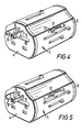
- the upper slide 6 is formed in one-piece from hard plastics material and comprises a bifurcated body of generally rectangular form from which two legs 7 extend rearwardly. Opposed inwardly directed shelves 40 along each casing inner side wall provide guide structure in which the slide moves longitudinally in in the body.
- a pair of contact pins 8 extend forwardly from the slide through slots 9 in the body front cover 4.
- the pins are of two-part construction with a flat front part 8f and a rear part 8r.
- Part 8f is in the form of a strip and part 8r in the form of a cylinder mounted for limited rotation about its axis-The forward position of the slide offers two pin configurations, with the pins straight for the USA in Figure 4 and in Figure 5 the pins rotated about the long axes to an inclined position for Australian and New Zealand sockets.
- An integrally formed resiliently flexible limb 11 extends forwardly and outwardly from each leg 7 to a laterally outwardly extending operating part or lug 12. Under the lug 12 is provided a detent projection 13.
- An inwardly extending stop 14 is provided to limit inward flexing of limb 11.
- the casing 1 has, at each side, an elongate rectangular slot 15 within which the lug 12 can be moved between front and rear positions to advance the pins 8.
- On the lower wall of each slot are provided front and rear detent recesses 16 and 17.
- the section A - A shown in Figure 6 and the corresponding later section show the slide in divided form, one half, the right half, showing the retracted slide with the projection 13 engaging the slot 17 whilst on the left hand side the pin is shown advanced with the projection 13 engaging the recess 16.
- the slide In both front and rear position the slide is securely locked until the lug is depressed to free the projection 13 from the respective detent. Excessive inward movement of the lug is limited by abutment of the stop 14 on the main body of the slide.
- the limbs 11 are deeper than the slots 15 so that in the forward position the limbs close the slot and act as a safety shroud.
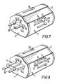
- Figures 7, 8 and 9 illustrate the intermediate pair of lugs selectively advancing round profile pins 18 through a wide slot 19 in front cover 4.
- the pins are effectively an electrically conductive tip and core in an electrically insulating body.
- the slide is constructed as before, and like parts are identified by like reference numerals. It should be noted however, that the slot 20 in which operating lug 21 moves is substantially greater length than the slot 15 and has not only front and rear detents but an intermediate detent 22 shown engaged in Figure 71
- the section on Figure 9 corresponds to Figure 8 and shows the slide 6 advanced to the front position with a part to mate with the German "Shuko" type recessed socket.
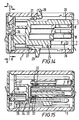
- Figure 12 and the corresponding sections in Figures 13 and 14 represent a three-pin array for U.K. sockets however require more detailed description.
- the slide 25 carrying the three conductive-tipped pins 26 comprises a vertically disposed generally C-shaped member with limbs 27 corresponding to the limbs 11 of Figure 6 with the operating lugs 28, 29 on the upper and lower walls of case 1 and similar detent and stop arrangements.
- a basal cross-member 30 serving as the carrier for the lower round pins, the operating limb 27 with the lug 29 protruding from the underside of this member 30.
- the operation comprises resilient depression of the limbs and sliding engagement of the studs with the detents.
- Each conductive pin has a rear conductive fixing to a conductive shoe 32.
- a U-shaped conductor 33 live or neutral according to the casing side.
- the shoes 32 of the upper pins engage the upper surface of the upper limb of conductor 33 and the bottom pair of pins the undersurface.
- Each U-shaped conductor is fastened to a bulkhead 34 by a conductive pin 38 ( Figure 17) passing through the bulkhead to a resiliently flexible conductive channel 35 constituting a socket member.
- bulkhead 34 forms part of transversely extending wall structure 37 extending across the rear of the interior of casing 1- This structure not only houses socket channels 35 but also provides a guide and back stop for the rear of the slides.
- Means can be provided for connecting the upper flat pin of the British type arrangement to the rear earth socket.
- the pin 26 will be made of insulating plastic-
- a movable safety shutter 36 (see Figure 16) is provided inside rear cover 5. This shutter, under spring bias covers entrances 31 until pushed aside by an entering plug.
- the slides 5, 7, 8 and 10 are formed for sliding interengagement with one another-
- the rear of the casing may include a voltage converter/transformer with control means on the casing exterior- The adapter can thus deal with different voltage values in a power supply.
- the terminal tips may be of electrically insulating material.
Abstract
Description
- This invention relates to a plug-in electrical connecting device having a plurality of pin arrays, selectable to suit the appropriate mains power source to the locality of use. With the appropriate pin assembly selected and plugged in the device provides a power socket for an appliance with a plug which would not otherwise be usable. Such a multi-pin device will hereinafter be referred to as an "adaptor".
- According to one aspect the present invention provides an adaptor comprising a casing, a plurality of sliding carriers each carrying an array of pins and slidable between a rear, pins-retracted position, and at least one forward, pins-protruding position, the carriers being disposed in stacked relationship and means for moving a selected one of the said carriers between the forward and rear positions.
- More specifically and in accordance with another aspect of the present invention an adaptor comprises a casing, a plurality of sliding carriers in the casing each carrying an array of pins and slidable between a rear, pins-retracted, position and at least one front, pins-protruding, position, opposed guides in the casing wall engaged by complementary parts on the carrier and releasable detent means operable from outside the casing, the arrangement being that with a carrier moved at least to a front position and preferably also to the rear position the detent moans operates securely to locate the carrier in that position until the detent is released.
- Each sliding carrier will be conductively associated with appropriate means to connect the pin to the socket or other appliance connection at the rear of the adaptor.
- Although other forms of carrier arrays can be envisaged with the releasable detent means the stacked is preferred- It is further preferred that operating lugs or other means for the carrier should also release and engage the detent means. These functions can however be separated.
- In an embodiment the guides are slots extending along diametrically opposed positions in the walls of a tubular casing. A resiliently flexible limb extends from each side of a sliding carrier, each limb having an outwardly directed operating part to pass through the slot and being laterally inwardly movable against its resilience from outside the casing- The limb also has a projection to engage with corresponding notches on the casing thereby providing the detent. This arrangement can obviously be reversed with notches on the limb and projections on the casing. In use the operating parts can be used to move the sliding carrier and on arrival at an opposed pair of detents the limbs flex to lock the carrier. The sliding carrier can be disengaged from the detents by inward compression of the limbs against their inherent resilience.
- A particular embodiment of the invention will now be described by way of example and with reference to the accompanying drawings wherein:-
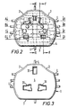
- Figure 1 is a perspective view of an adaptor in accordance with the invention with all the slides and pins retracted;
- Figure 2 is a front view of the adaptor with the interior components shown in dotted lines;
- Figure 3 is a rear view of the adaptor;
- Figures 4 and 5 are perspective views of the adaptor with one of the slides advanced to the forward position with pins protruding, alternative angular orientation of the pins being shown;
- Figure 6 is a section on the line-A - A of Figure 2 showing the advancing slide of Figures 4 and 5;
- Figure 7 is a perspective view showing the adaptor with another slide advanced to a first position;
- Figure 8 is a similar view indicating the slide shown in Figure 7 advanced further to a second position;
- Figure 9 is a section on the line B - B of Figure 2 showing the advancing slide Figures 7 and 8.
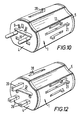
- Figure 10 is a perspective view of the adaptor with another slide advanced;
- Figure 11 is a section on the line C - C of Figure 9 showing the advancing slide of Figure 10;
- Figure 12 is a perspective view showing another slide advanced, that carrying three pins;
- Figures 13 and 14 are sections on the line D - D and E - E of Figure 2 showing the advancing slide of Figure 12;
- Figure 15 is a section on the line F - F of Figure 2 showing how the pins in the slides are electrically energised; and
- Figures 16 and 17 are sections on the line G - G and H - H of Figure 14 illustrating the rear socket arrangement of the adaptor.
- Referring now to Figure 1 of the drawings the adaptor illustrated comprises a
tubular plastics casing 1 of rounded cross-section with chamferedtop portions 2 to provide grip, and aflattened base 3. The casing has front and rear end covers 4 and 5. Thefront cover 4 has a plurality of apertures (a), to be described, to allow passage of pin arrays- Also well seen in Figure 1 are operating lugs L to advance selectively the required pin arrays. These lugs will be systematically described hereinafter- At this stage it can be noted that there are an upper pair of lugs, an intermediate pair of lugs and a lower pair of lugs on opposed side walls and a pair of lugs on the upper and lower surfaces. Depending on the selective advance and retreat of a chosen lug pair a particular pin configuration is bought forward into an operating condition for engagement with a particular socket configuration- The appliance to be used can be plugged intosocket apertures 31 at the rear of the casing- Theseapertures 31 can accept two and three pin configurations. - Returning to the detailed description reference will initially be made to Figures 4, 5 and 6. The
upper slide 6 is formed in one-piece from hard plastics material and comprises a bifurcated body of generally rectangular form from which twolegs 7 extend rearwardly. Opposed inwardly directedshelves 40 along each casing inner side wall provide guide structure in which the slide moves longitudinally in in the body. A pair ofcontact pins 8 extend forwardly from the slide throughslots 9 in thebody front cover 4. The pins are of two-part construction with a flat front part 8f and a rear part 8r. Part 8f is in the form of a strip and part 8r in the form of a cylinder mounted for limited rotation about its axis-The forward position of the slide offers two pin configurations, with the pins straight for the USA in Figure 4 and in Figure 5 the pins rotated about the long axes to an inclined position for Australian and New Zealand sockets. An integrally formed resilientlyflexible limb 11 extends forwardly and outwardly from eachleg 7 to a laterally outwardly extending operating part orlug 12. Under thelug 12 is provided adetent projection 13. An inwardly extendingstop 14 is provided to limit inward flexing oflimb 11. Thecasing 1 has, at each side, an elongaterectangular slot 15 within which thelug 12 can be moved between front and rear positions to advance thepins 8. On the lower wall of each slot are provided front and reardetent recesses - The section A - A shown in Figure 6 and the corresponding later section show the slide in divided form, one half, the right half, showing the retracted slide with the
projection 13 engaging theslot 17 whilst on the left hand side the pin is shown advanced with theprojection 13 engaging therecess 16. In both front and rear position the slide is securely locked until the lug is depressed to free theprojection 13 from the respective detent. Excessive inward movement of the lug is limited by abutment of thestop 14 on the main body of the slide. Thelimbs 11 are deeper than theslots 15 so that in the forward position the limbs close the slot and act as a safety shroud. - Figures 7, 8 and 9 illustrate the intermediate pair of lugs selectively advancing
round profile pins 18 through awide slot 19 infront cover 4. In this slide and indeed in the slides described hereinafter the pins are effectively an electrically conductive tip and core in an electrically insulating body. The slide is constructed as before, and like parts are identified by like reference numerals. It should be noted however, that theslot 20 in which operatinglug 21 moves is substantially greater length than theslot 15 and has not only front and rear detents but anintermediate detent 22 shown engaged in Figure 71 The section on Figure 9 corresponds to Figure 8 and shows theslide 6 advanced to the front position with a part to mate with the German "Shuko" type recessed socket. In the intermediate position with thedetent projection 13 engaging the intermediatedetent recess 22 the front of theslide 6 is flush with the front of the case and that is the configuration shown in Figure 7. This is the configuration for other countries on the continent of Europe such as Spain. Differences in the guide structure in the casing for the slide should also be noted. Elongate guide posts 24 engagemating sockets 25 in the rear of the slide. - The configuration shown in Figures 10 and 11 requires little comment though again the rear of the slide has a slightly different configuration. Again like reference numerals identify like parts. In principle however, the arrangement is similar to that described with reference to Figures 4 to 6. The pins are for Italian sockets.
- Figure 12 and the corresponding sections in Figures 13 and 14 represent a three-pin array for U.K. sockets however require more detailed description.
- The
slide 25 carrying the three conductive-tippedpins 26 comprises a vertically disposed generally C-shaped member withlimbs 27 corresponding to thelimbs 11 of Figure 6 with theoperating lugs case 1 and similar detent and stop arrangements. There is also provided as can best be seen from Figure 13 abasal cross-member 30 serving as the carrier for the lower round pins, theoperating limb 27 with thelug 29 protruding from the underside of thismember 30. As before the operation comprises resilient depression of the limbs and sliding engagement of the studs with the detents. - The electrical connection arrangement to the rear socket entrances 31 (see Figure 3) can be appreciated from Figures 15 to 17. Each conductive pin has a rear conductive fixing to a
conductive shoe 32. On each side of the casing is disposed aU-shaped conductor 33, live or neutral according to the casing side. Theshoes 32 of the upper pins engage the upper surface of the upper limb ofconductor 33 and the bottom pair of pins the undersurface. Each U-shaped conductor is fastened to abulkhead 34 by a conductive pin 38 (Figure 17) passing through the bulkhead to a resiliently flexibleconductive channel 35 constituting a socket member. As can best be seen from Figures 17 and 15bulkhead 34 forms part of transversely extendingwall structure 37 extending across the rear of the interior of casing 1- This structure not only housessocket channels 35 but also provides a guide and back stop for the rear of the slides. - Means can be provided for connecting the upper flat pin of the British type arrangement to the rear earth socket. In the absence of such connection the
pin 26 will be made of insulating plastic- A movable safety shutter 36 (see Figure 16) is provided insiderear cover 5. This shutter, under spring bias coversentrances 31 until pushed aside by an entering plug. - In an alternative construction the
slides - In the device, as described above, the possibility exists for two or more slides to be advanced together. This is undesirable from the standpoint of safety and it is proposed to incorporate some means such as a rotatable shutter which obstructs the forward sliding of all but a selected slide- As an alternative the terminal tips may be of electrically insulating material.
Claims (6)
Priority Applications (1)
| Application Number | Priority Date | Filing Date | Title |
|---|---|---|---|
| AT84308875T ATE35487T1 (en) | 1984-02-08 | 1984-12-18 | ADAPTER WITH SLIDING PIN HOLDER. |
Applications Claiming Priority (2)
| Application Number | Priority Date | Filing Date | Title |
|---|---|---|---|
| GB8403294 | 1984-02-08 | ||
| GB848403294A GB8403294D0 (en) | 1984-02-08 | 1984-02-08 | Electrical connectors |
Publications (2)
| Publication Number | Publication Date |
|---|---|
| EP0156076A1 true EP0156076A1 (en) | 1985-10-02 |
| EP0156076B1 EP0156076B1 (en) | 1988-06-29 |
Family
ID=10556264
Family Applications (1)
| Application Number | Title | Priority Date | Filing Date |
|---|---|---|---|
| EP84308875A Expired EP0156076B1 (en) | 1984-02-08 | 1984-12-18 | Adaptor comprising sliding pin carriers |
Country Status (10)
| Country | Link |
|---|---|
| US (1) | US4626052A (en) |
| EP (1) | EP0156076B1 (en) |
| JP (1) | JPS60258879A (en) |
| AT (1) | ATE35487T1 (en) |
| AU (1) | AU564903B2 (en) |
| CA (1) | CA1236193A (en) |
| DE (1) | DE3472506D1 (en) |
| ES (1) | ES295784Y (en) |
| GB (1) | GB8403294D0 (en) |
| ZA (1) | ZA8516B (en) |
Cited By (10)
| Publication number | Priority date | Publication date | Assignee | Title |
|---|---|---|---|---|
| EP0477636A1 (en) * | 1990-09-25 | 1992-04-01 | Reinhard Napierski | Electrical adapter |
| EP0617485A2 (en) * | 1993-03-23 | 1994-09-28 | Optical Coating Laboratory, Inc. | International electrical ground connector-adaptor for computer monitor |
| US5474464A (en) * | 1991-09-10 | 1995-12-12 | Rutland Gilts Limited | Electrical adaptor |
| EP1178577A2 (en) * | 2000-08-02 | 2002-02-06 | Philips Corporate Intellectual Property GmbH | Device for establishing an electrical connection |
| WO2009152632A1 (en) * | 2008-06-17 | 2009-12-23 | Walter Ruffner | Multi-way slide plug with slide locking |
| WO2009152630A1 (en) * | 2008-06-17 | 2009-12-23 | Walter Ruffner | Multi-way sliding plug |
| US8142208B2 (en) | 2008-06-17 | 2012-03-27 | Walter Ruffner | Adapter plug |
| US8382493B2 (en) | 2008-06-17 | 2013-02-26 | Walter Ruffner | Three-pole adapter set with a plug part and a socket part which may be plugged in the plug part |
| CN105576408A (en) * | 2015-12-21 | 2016-05-11 | 公牛集团有限公司 | Converter having key selection function |
| EP3252884A1 (en) * | 2016-06-01 | 2017-12-06 | Travel Blue Limited | Compact travelling plug |
Families Citing this family (60)
| Publication number | Priority date | Publication date | Assignee | Title |
|---|---|---|---|---|
| US4815983A (en) * | 1987-11-13 | 1989-03-28 | International Business Machines Corporation | Customizable plugs for A.C. power cords |
| SE468536B (en) * | 1991-07-03 | 1993-02-01 | Bolin Mauritz Ingf Ab | PLUG |
| US5423690A (en) * | 1994-02-02 | 1995-06-13 | International Business Machines Corporation | Universal electrical power plug for multination use with self-setting contact pins |
| TW255989B (en) * | 1994-02-24 | 1995-09-01 | Asian Micro Sources Inc | Collapsible prong plug device for battery charger |
| TW268155B (en) * | 1994-02-24 | 1996-01-11 | Asian Micro Sources Inc | Collapsible plug device for battery charger |
| US6227888B1 (en) | 1994-02-24 | 2001-05-08 | Advanced Mobile Solutions, Inc. | Interchangeable plug device |
| US5634806A (en) * | 1994-02-24 | 1997-06-03 | Asian Micro Sources, Inc. | Interchangeable collapsible plug device for battery charger |
| US5648712A (en) * | 1995-08-29 | 1997-07-15 | Asian Micro Sources, Inc. | Universally interchangeable and modular power supply with integrated battery charger |
| USD381314S (en) * | 1995-09-15 | 1997-07-22 | Asian Micro Sources, Inc. | Interchangeable plug device |
| USD381627S (en) * | 1995-10-06 | 1997-07-29 | Philips Electronics North America Corporation | Adaptor |
| USD379619S (en) * | 1995-10-06 | 1997-06-03 | Philips Electronics North America Corporation | Adaptor |
| USD384328S (en) * | 1995-10-06 | 1997-09-30 | Philips Electronics North America Corporation | Adaptor |
| USD382854S (en) * | 1995-10-06 | 1997-08-26 | Philips Electronics North America Corporation | Adaptor |
| US5684689A (en) * | 1996-06-19 | 1997-11-04 | Advanced Mobile Solutions, Inc. | Interchangeable plug power supply with automatically adjusting input voltage receiving mechanism |
| KR100573088B1 (en) * | 1998-07-20 | 2006-09-22 | (주)한국이에프티엔지니어링 | Grounding plug device |
| US6062884A (en) * | 1998-09-11 | 2000-05-16 | Hybrinetics, Inc. | Rotationally activated multiple plug receptacle adapter |
| US6139341A (en) * | 1998-12-02 | 2000-10-31 | Taiwan Semiconductor Manufacturing Company, Ltd | Universal adapter equipped with retractable pins |
| US7367121B1 (en) | 2000-01-05 | 2008-05-06 | Protectconnect | Electrical wiring method |
| US6979212B1 (en) * | 2000-01-14 | 2005-12-27 | Protect Connect | Safety electrical plug |
| KR100401302B1 (en) * | 2000-02-15 | 2003-10-10 | 최진영 | Electric plug |
| EP1170836A1 (en) * | 2000-07-05 | 2002-01-09 | Tat Kwong Cheung | Universal adapter |
| DE10102713B4 (en) * | 2001-01-22 | 2004-12-09 | Friwo Gerätebau Gmbh | Plug-in power supply with miniaturized primary contact |
| AU2002302289A1 (en) * | 2001-06-05 | 2002-08-19 | Mcruff Ag | Mains plug |
| US6382996B1 (en) * | 2001-06-11 | 2002-05-07 | E & B Giftware Llc | Worldwide adaptor plug |
| KR100438988B1 (en) * | 2001-08-29 | 2004-07-07 | 주식회사 배산엔지니어링 | adapter |
| EP1512197A4 (en) | 2002-05-23 | 2006-12-20 | Protectconnect Inc | Safety module electrical distribution system |
| DE60207845T8 (en) * | 2002-07-19 | 2007-10-04 | Emanuela Dr. Bona | Electric adapter |
| US6939150B1 (en) * | 2002-08-01 | 2005-09-06 | Comarco Wireless Technologies, Inc. | Foldable electrical plug connector |
| CN2582224Y (en) * | 2002-12-05 | 2003-10-22 | 张锡帆 | Communication connector adapter |
| US20050026880A1 (en) * | 2003-07-31 | 2005-02-03 | Robinson Cynthia B. | Combination of dehydroepiandrosterone or dehydroepiandrosterone-sulfate with a cromone for treatment of asthma or chronic obstructive pulmonary disease |
| US7038463B2 (en) * | 2003-08-01 | 2006-05-02 | Cooper Ted J | Method and apparatus for battery reconfiguration for radio control application |
| DE10351123B3 (en) * | 2003-11-03 | 2005-06-02 | Moeller Gmbh | Device combination of two electromagnetic switching devices |
| TWM251363U (en) * | 2004-01-09 | 2004-11-21 | Sheng-Shing Liau | Multi-functional plug switch |
| US9153960B2 (en) | 2004-01-15 | 2015-10-06 | Comarco Wireless Technologies, Inc. | Power supply equipment utilizing interchangeable tips to provide power and a data signal to electronic devices |
| US7312396B1 (en) | 2004-03-13 | 2007-12-25 | Protectconnect, Inc. | Universal electrical wiring component |
| US7121850B2 (en) * | 2004-11-05 | 2006-10-17 | Ming-Hsiang Yeh | Dual-purpose male/female connector |
| US20060141865A1 (en) * | 2004-12-27 | 2006-06-29 | Behavior Tech Computer Corp. | Combo-type male and female universal series bus connector |
| TWI273370B (en) * | 2005-03-16 | 2007-02-11 | Benq Corp | Electronic device with various signal transmission connectors |
| BRPI0613114A2 (en) * | 2005-07-08 | 2010-12-21 | Eduard Mathieu Antonius Zijlstra | sliding pin plug and locking device |
| US7066745B1 (en) * | 2005-10-17 | 2006-06-27 | Chi-Wen Chen | Power supply connector |
| US20080053698A1 (en) | 2006-07-29 | 2008-03-06 | Steve Purves | Pre-wired power distribution system |
| US7575436B1 (en) * | 2008-02-06 | 2009-08-18 | Southwire Company | Rotating plug adapter with integral two blade receptacle |
| US7985083B2 (en) * | 2009-05-18 | 2011-07-26 | Phihong Usa Corporation | Interface between connectable electrical devices |
| CN201490530U (en) * | 2009-06-05 | 2010-05-26 | 东莞欧陆电子有限公司 | Multinational type power conversion socket |
| KR101651686B1 (en) * | 2010-08-27 | 2016-08-26 | 삼성전자주식회사 | Contact terminal covering device |
| DE102011014920B4 (en) * | 2011-03-24 | 2013-02-21 | Xyz Science Co., Ltd. | Universal plug adapter with different pin constructions |
| GB2501012B (en) * | 2011-09-16 | 2013-12-25 | Dg Int Holdings Ltd | An adaptor for adapting a mains plug and a mains cable featuring an adaptor mechanism |
| CN102361201B (en) * | 2011-09-23 | 2014-06-18 | 公牛集团有限公司 | Plug dislocation interlocking apparatus used by general-purpose converter |
| US8550827B1 (en) * | 2012-07-25 | 2013-10-08 | Targus Group International, Inc. | Multi-sleeve power tips |
| US8821199B2 (en) | 2012-07-25 | 2014-09-02 | Targus Group International, Inc. | Multi-prong power tip adaptor |
| US9406462B2 (en) * | 2013-06-28 | 2016-08-02 | The Boeing Company | Truss interconnect |
| USD746233S1 (en) * | 2014-01-02 | 2015-12-29 | Jeffrey Lyons | Extension cord plug |
| TWI583072B (en) * | 2014-07-17 | 2017-05-11 | 緯創資通股份有限公司 | Positioned structure and connector assembly |
| US9831622B1 (en) * | 2017-04-14 | 2017-11-28 | Yuying Lin | Universal socket converter with power bank |
| USD873218S1 (en) * | 2017-08-22 | 2020-01-21 | Shenzhen Uppel Technology Co., Ltd | Travel charger |
| USD864863S1 (en) * | 2017-08-31 | 2019-10-29 | Kuang-Hao Lee | All in one travel converter |
| USD897278S1 (en) * | 2018-07-14 | 2020-09-29 | Zhaokun Zeng | Power converter |
| US10587084B1 (en) * | 2018-11-01 | 2020-03-10 | Wonpro Co., Ltd. | Multinational adapter structure |
| JP2020098670A (en) * | 2018-12-17 | 2020-06-25 | 洋基科技有限公司Wonpro Co., Ltd | Universal adapter structure |
| CN110098545A (en) | 2019-05-30 | 2019-08-06 | 公牛集团股份有限公司 | A kind of converter |
Citations (3)
| Publication number | Priority date | Publication date | Assignee | Title |
|---|---|---|---|---|
| DE3109620A1 (en) * | 1981-03-13 | 1982-09-23 | Manfred Dr. 8520 Erlangen Herbst | Worldwide travel-plug adapter |
| GB2097202A (en) * | 1981-04-06 | 1982-10-27 | Corabelment Ag | Electrical adaptor |
| EP0104279A1 (en) * | 1982-08-04 | 1984-04-04 | Corabelment A.G. | Multiple pin electrical plug |
Family Cites Families (3)
| Publication number | Priority date | Publication date | Assignee | Title |
|---|---|---|---|---|
| US2163201A (en) * | 1936-03-13 | 1939-06-20 | Kalencik Paul | Analyzer plug |
| US3025486A (en) * | 1960-02-10 | 1962-03-13 | Falconer John Henry | Three way electric plug |
| DE3275614D1 (en) * | 1982-01-18 | 1987-04-09 | Corabelment Ag | Unitary electrical plug with multiple inlets and voltage converter |
-
1984
- 1984-02-08 GB GB848403294A patent/GB8403294D0/en active Pending
- 1984-12-18 EP EP84308875A patent/EP0156076B1/en not_active Expired
- 1984-12-18 DE DE8484308875T patent/DE3472506D1/en not_active Expired
- 1984-12-18 AT AT84308875T patent/ATE35487T1/en not_active IP Right Cessation
-
1985
- 1985-01-02 ZA ZA8516A patent/ZA8516B/en unknown
- 1985-01-09 CA CA000471760A patent/CA1236193A/en not_active Expired
- 1985-02-06 US US06/698,882 patent/US4626052A/en not_active Expired - Fee Related
- 1985-02-06 AU AU38472/85A patent/AU564903B2/en not_active Ceased
- 1985-02-07 ES ES1985295784U patent/ES295784Y/en not_active Expired
- 1985-02-08 JP JP60022117A patent/JPS60258879A/en active Pending
Patent Citations (3)
| Publication number | Priority date | Publication date | Assignee | Title |
|---|---|---|---|---|
| DE3109620A1 (en) * | 1981-03-13 | 1982-09-23 | Manfred Dr. 8520 Erlangen Herbst | Worldwide travel-plug adapter |
| GB2097202A (en) * | 1981-04-06 | 1982-10-27 | Corabelment Ag | Electrical adaptor |
| EP0104279A1 (en) * | 1982-08-04 | 1984-04-04 | Corabelment A.G. | Multiple pin electrical plug |
Cited By (17)
| Publication number | Priority date | Publication date | Assignee | Title |
|---|---|---|---|---|
| EP0477636A1 (en) * | 1990-09-25 | 1992-04-01 | Reinhard Napierski | Electrical adapter |
| US5474464A (en) * | 1991-09-10 | 1995-12-12 | Rutland Gilts Limited | Electrical adaptor |
| EP0617485A2 (en) * | 1993-03-23 | 1994-09-28 | Optical Coating Laboratory, Inc. | International electrical ground connector-adaptor for computer monitor |
| EP0617485A3 (en) * | 1993-03-23 | 1996-03-27 | Optical Coating Laboratory Inc | International electrical ground connector-adaptor for computer monitor. |
| EP1178577A2 (en) * | 2000-08-02 | 2002-02-06 | Philips Corporate Intellectual Property GmbH | Device for establishing an electrical connection |
| EP1178577A3 (en) * | 2000-08-02 | 2003-01-29 | Philips Corporate Intellectual Property GmbH | Device for establishing an electrical connection |
| US8142208B2 (en) | 2008-06-17 | 2012-03-27 | Walter Ruffner | Adapter plug |
| WO2009152630A1 (en) * | 2008-06-17 | 2009-12-23 | Walter Ruffner | Multi-way sliding plug |
| WO2009152632A1 (en) * | 2008-06-17 | 2009-12-23 | Walter Ruffner | Multi-way slide plug with slide locking |
| US8182276B2 (en) | 2008-06-17 | 2012-05-22 | Walter Ruffner | Multi-way sliding plug |
| US8382493B2 (en) | 2008-06-17 | 2013-02-26 | Walter Ruffner | Three-pole adapter set with a plug part and a socket part which may be plugged in the plug part |
| EP2297824B1 (en) | 2008-06-17 | 2016-12-14 | Walter Ruffner | Three-pole adapter set with a plug part and a socket part which may be plugged in the plug part |
| CN105576408A (en) * | 2015-12-21 | 2016-05-11 | 公牛集团有限公司 | Converter having key selection function |
| EP3252884A1 (en) * | 2016-06-01 | 2017-12-06 | Travel Blue Limited | Compact travelling plug |
| WO2017207096A1 (en) * | 2016-06-01 | 2017-12-07 | Travel Blue Ltd., Magnolia House | Compact travel plug |
| CN109314356A (en) * | 2016-06-01 | 2019-02-05 | 蓝旅有限公司 | Succinct changeover plug |
| CN109314356B (en) * | 2016-06-01 | 2021-02-12 | 蓝旅有限公司 | Simple conversion plug |
Also Published As
| Publication number | Publication date |
|---|---|
| DE3472506D1 (en) | 1988-08-04 |
| AU3847285A (en) | 1985-08-15 |
| US4626052A (en) | 1986-12-02 |
| ATE35487T1 (en) | 1988-07-15 |
| JPS60258879A (en) | 1985-12-20 |
| ES295784U (en) | 1987-06-16 |
| AU564903B2 (en) | 1987-08-27 |
| ES295784Y (en) | 1987-12-16 |
| GB8403294D0 (en) | 1984-03-14 |
| CA1236193A (en) | 1988-05-03 |
| EP0156076B1 (en) | 1988-06-29 |
| ZA8516B (en) | 1986-03-26 |
Similar Documents
| Publication | Publication Date | Title |
|---|---|---|
| EP0156076A1 (en) | Adaptor comprising sliding pin carriers | |
| TWI555284B (en) | Connector | |
| KR0139588B1 (en) | Shunted connector assembly and shunt assembly for it | |
| JP3043360B2 (en) | Connector structure having encoding means | |
| US3754205A (en) | Protected connector plug | |
| US4932886A (en) | Shockproof electrical outlet | |
| JPH01304674A (en) | Connector for electric distrbution system | |
| US4778397A (en) | Track lighting system and connecting plug with sliding lock | |
| US4201431A (en) | Universal adaptable three-prong electrical plug | |
| BR112014018987A2 (en) | electrical coupling element | |
| US4345122A (en) | Detachable cord | |
| JP2627966B2 (en) | Shunt connector | |
| US5595498A (en) | Connector for electrical trunking | |
| CN111969350B (en) | Simple travel conversion plug capable of being grounded | |
| US2966651A (en) | Three to two-wire plug adapter with grounding pigtail | |
| US4447102A (en) | Electrical connector assemblies | |
| US3421136A (en) | Electrical contact and edge connector having such a contact | |
| EP1383203B1 (en) | Anti-overstress electrical connector | |
| US20230115610A1 (en) | Socket connector for a connector system | |
| US2316072A (en) | Connector plug | |
| US6926550B2 (en) | Self-locking electrical receptacle having safety protector | |
| US3601749A (en) | Input connector for electric distribution tracks | |
| KR860001185Y1 (en) | Power socket | |
| JP2529772B2 (en) | Connector with mating confirmation mechanism | |
| GB2139001A (en) | Electrical socket outlet |
Legal Events
| Date | Code | Title | Description |
|---|---|---|---|
| PUAI | Public reference made under article 153(3) epc to a published international application that has entered the european phase |
Free format text: ORIGINAL CODE: 0009012 |
|
| AK | Designated contracting states |
Designated state(s): AT BE CH DE FR GB IT LI LU NL SE |
|
| 17P | Request for examination filed |
Effective date: 19851223 |
|
| 17Q | First examination report despatched |
Effective date: 19870331 |
|
| GRAA | (expected) grant |
Free format text: ORIGINAL CODE: 0009210 |
|
| AK | Designated contracting states |
Kind code of ref document: B1 Designated state(s): AT BE CH DE FR GB IT LI LU NL SE |
|
| REF | Corresponds to: |
Ref document number: 35487 Country of ref document: AT Date of ref document: 19880715 Kind code of ref document: T |
|
| ITF | It: translation for a ep patent filed |
Owner name: JACOBACCI & PERANI S.P.A. |
|
| REF | Corresponds to: |
Ref document number: 3472506 Country of ref document: DE Date of ref document: 19880804 |
|
| ET | Fr: translation filed | ||
| PG25 | Lapsed in a contracting state [announced via postgrant information from national office to epo] |
Ref country code: LU Free format text: LAPSE BECAUSE OF NON-PAYMENT OF DUE FEES Effective date: 19881231 |
|
| PLBE | No opposition filed within time limit |
Free format text: ORIGINAL CODE: 0009261 |
|
| STAA | Information on the status of an ep patent application or granted ep patent |
Free format text: STATUS: NO OPPOSITION FILED WITHIN TIME LIMIT |
|
| 26N | No opposition filed | ||
| PGFP | Annual fee paid to national office [announced via postgrant information from national office to epo] |
Ref country code: LU Payment date: 19891127 Year of fee payment: 6 |
|
| PGFP | Annual fee paid to national office [announced via postgrant information from national office to epo] |
Ref country code: BE Payment date: 19891211 Year of fee payment: 6 |
|
| PGFP | Annual fee paid to national office [announced via postgrant information from national office to epo] |
Ref country code: AT Payment date: 19891215 Year of fee payment: 6 |
|
| PGFP | Annual fee paid to national office [announced via postgrant information from national office to epo] |
Ref country code: SE Payment date: 19891222 Year of fee payment: 6 |
|
| PG25 | Lapsed in a contracting state [announced via postgrant information from national office to epo] |
Ref country code: AT Effective date: 19901218 |
|
| PG25 | Lapsed in a contracting state [announced via postgrant information from national office to epo] |
Ref country code: SE Effective date: 19901219 |
|
| ITTA | It: last paid annual fee | ||
| PG25 | Lapsed in a contracting state [announced via postgrant information from national office to epo] |
Ref country code: BE Effective date: 19901231 |
|
| BERE | Be: lapsed |
Owner name: RUMBLE CLIVE ST. JOHN Effective date: 19901231 |
|
| REG | Reference to a national code |
Ref country code: CH Ref legal event code: PUE Owner name: CORABELMENT AG |
|
| REG | Reference to a national code |
Ref country code: GB Ref legal event code: 732 |
|
| NLS | Nl: assignments of ep-patents |
Owner name: CORABELMENT AG TE VADUZ, LIECHTENSTEIN. |
|
| REG | Reference to a national code |
Ref country code: FR Ref legal event code: TP |
|
| ITPR | It: changes in ownership of a european patent |
Owner name: CESSIONE;CARABELMENT AG |
|
| EUG | Se: european patent has lapsed |
Ref document number: 84308875.8 Effective date: 19910910 |
|
| PGFP | Annual fee paid to national office [announced via postgrant information from national office to epo] |
Ref country code: CH Payment date: 19950616 Year of fee payment: 11 |
|
| PGFP | Annual fee paid to national office [announced via postgrant information from national office to epo] |
Ref country code: NL Payment date: 19950630 Year of fee payment: 11 |
|
| PG25 | Lapsed in a contracting state [announced via postgrant information from national office to epo] |
Ref country code: LI Effective date: 19951231 Ref country code: CH Effective date: 19951231 |
|
| PGFP | Annual fee paid to national office [announced via postgrant information from national office to epo] |
Ref country code: FR Payment date: 19960625 Year of fee payment: 12 |
|
| PGFP | Annual fee paid to national office [announced via postgrant information from national office to epo] |
Ref country code: DE Payment date: 19960628 Year of fee payment: 12 |
|
| PG25 | Lapsed in a contracting state [announced via postgrant information from national office to epo] |
Ref country code: NL Effective date: 19960701 |
|
| REG | Reference to a national code |
Ref country code: CH Ref legal event code: PL |
|
| NLV4 | Nl: lapsed or anulled due to non-payment of the annual fee |
Effective date: 19960701 |
|
| PG25 | Lapsed in a contracting state [announced via postgrant information from national office to epo] |
Ref country code: FR Effective date: 19970829 |
|
| PG25 | Lapsed in a contracting state [announced via postgrant information from national office to epo] |
Ref country code: DE Effective date: 19970902 |
|
| REG | Reference to a national code |
Ref country code: FR Ref legal event code: ST |
|
| PGFP | Annual fee paid to national office [announced via postgrant information from national office to epo] |
Ref country code: GB Payment date: 19980615 Year of fee payment: 14 |
|
| PG25 | Lapsed in a contracting state [announced via postgrant information from national office to epo] |
Ref country code: GB Free format text: LAPSE BECAUSE OF NON-PAYMENT OF DUE FEES Effective date: 19981218 |
|
| GBPC | Gb: european patent ceased through non-payment of renewal fee |
Effective date: 19981218 |