EP0155789A2 - Apparatus for automatically inspecting printed labels - Google Patents
Apparatus for automatically inspecting printed labels Download PDFInfo
- Publication number
- EP0155789A2 EP0155789A2 EP85301421A EP85301421A EP0155789A2 EP 0155789 A2 EP0155789 A2 EP 0155789A2 EP 85301421 A EP85301421 A EP 85301421A EP 85301421 A EP85301421 A EP 85301421A EP 0155789 A2 EP0155789 A2 EP 0155789A2
- Authority
- EP
- European Patent Office
- Prior art keywords
- label
- inspection
- operatively connected
- video
- pattern recognition
- Prior art date
- Legal status (The legal status is an assumption and is not a legal conclusion. Google has not performed a legal analysis and makes no representation as to the accuracy of the status listed.)
- Granted
Links
Images


Classifications
-
- B—PERFORMING OPERATIONS; TRANSPORTING
- B07—SEPARATING SOLIDS FROM SOLIDS; SORTING
- B07C—POSTAL SORTING; SORTING INDIVIDUAL ARTICLES, OR BULK MATERIAL FIT TO BE SORTED PIECE-MEAL, e.g. BY PICKING
- B07C5/00—Sorting according to a characteristic or feature of the articles or material being sorted, e.g. by control effected by devices which detect or measure such characteristic or feature; Sorting by manually actuated devices, e.g. switches
- B07C5/34—Sorting according to other particular properties
- B07C5/3412—Sorting according to other particular properties according to a code applied to the object which indicates a property of the object, e.g. quality class, contents or incorrect indication
-
- G—PHYSICS
- G06—COMPUTING; CALCULATING OR COUNTING
- G06F—ELECTRIC DIGITAL DATA PROCESSING
- G06F18/00—Pattern recognition
- G06F18/20—Analysing
- G06F18/21—Design or setup of recognition systems or techniques; Extraction of features in feature space; Blind source separation
Definitions
- This invention relates to inspection systems and more particularly to an apparatus for automatically inspecting printed labels.
- Label verification is important both to outgoing and incoming warehousing operations and when a large number of physically similar parts are handled, their labels may be the only way of differentiating among them.
- the labels may be the only way of differentiating bottles of pharmaceuticals, chemicals, blood samples, and semiconductor devices such as integrated circuits.
- the parts not only be verified as being correct but also legibly marked as they go out the door and recognizable as such at the receiving station.
- Another object of the invention is to provide an apparatus for determining whether the markings or labels are correct.
- a further object of the invention is to provide an apparatus for determining whether the label or marking is correctly positioned and oriented.
- Yet another object of the invention is to provide an apparatus having a monitor for supervising the operation of the apparatus.
- this invention comprises an apparatus for performing the automatic inspection of labels or marked manufactured products and verifying the correctness, orientation, and legibility of the label or marking.
- the apparatus includes a camera type viewing means for viewing the label or marking of a product and forming an electrical representation thereof for a pattern recognition and analysis circuit, and a monitor for monitoring the operation of the apparatus.
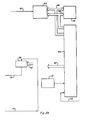
- the computer vision system 10 for automatically inspecting printed labels includes a materials handling means 12 holding a labeled product 14 for inspection of its label 16.
- a camera means 18 such as, for example, a television camera is positioned in a picture taking relationship to the label for taking a picture of the label.
- a pattern recognition circuit 20 is connected to the television camera 18 for performing the label inspection, hereinafter described.
- a joystick/keypad 22 and a picture monitor 24 are connected to the pattern recognition set. The monitor 24 is for physically viewing the operation of the system; whilst the joystick/keypad 22 is for selecting training and other functions, hereinafter described, for the system for label inspection.
- the "training" or as it often called “teaching" process and a label inspection process will be described hereinafter.
- the pattern recognition and analysis circuit 20, (Fig. 2a) comprises a video input, threshold and comparator means 26 connected to the television camera 18 for receiving the analog horizontal and vertical scans.
- the horizontal scan for example, consists of 256 rows and the vertical scan, for example, consists of 438 columns; thus, the picture includes, for example, 112,128 picture elements (pixels).
- the video input, threshold and comparator means 26 digitizes the video input into logic zeros ("0") for black and logic ones ("1") for white for producing a black and white digitized picture of the label.
- the video input threshold and comparator 26 is connected by lead 28 to a first terminal of an exclusive OR gate 30 and to an input pin 9 of a selector 32.
- the other terminal of exclusive OR gate 30 and pin 8 of selector 32 are connected by lead 34 to a refresh buffer 36.
- the selector 32 has pins 10 and 11 connected by leads 38 and 40 to a data processor's Control Register Unit (CRU) out bus 42 (Fig. 2b) of a data processor 44 for selecting, respectively, the refresh buffer input or the exclusive OR gate input.
- CRU Control Register Unit
- a plurality of label inspection lines can be multiplexed from a four channel board on conductor 46 (Fig. 2a) to pin 5 of selector 32 and a first terminal of exclusive OR gate 48.
- a second terminal of exclusive OR gate 48 is connected by lead 34 to pin 4 of the selector 32 and to the refresh buffer 36.
- a strap selection for the four channel board is connected by lead 50 to pin 1 of selector 32 for selecting and controlling the camera input and corresponding refresh buffer. It will be understood that the four camera system and the one camera system described are either/or cases and a five camera system is not described by combining them.
- the output pin 12 of selector 32 is connected to a two dimensional spatial low pass filter 52 which is, for example, a read only memory.
- the ROM 52 is connected by bus 54 to selector 56.
- Selector 56 is connected to the CRU out bus 42 (Fig. 2b) of data processor 44.
- the data processor sends operating signals selectively to activate the selector 56 (Fig. 2a) for purposes hereinafter described.
- Selector 56 has its output connected by lead 60 to a video mixer and display control means 62 and to a direct memory access (read and write) logic means 64 (Fig. 2b).
- the direct memory access logic means 64 is connected by a data transceiver bus 66 to a data processor memory 70 and the data processor 44, and by an address transceiver bus 68 to the data processor memory 70 and data processor 44.
- the direct memory access logic 64 has an output lead 72 connected to the refresh buffer 36 (Fig. 2a).
- Selector 32 when it receives refresh buffer 36 input select control signals on pin 10 from the data processor inputs picture difference data into the two dimensional spatial low pass filter 52; the filtered data is output on bus 54 to selector 56 which is controlled by the CRU out bus 42 signals of data processor 44.
- a selector 58 (Fig. 2b) acts as a switch controlled by the CRU out 42 of data processor 44 to admit window forming signals received from a window generator 90 (Fig. 2a) on lead 76 to the video mixer and display control circuit 62 for highlighting a portion of the image on monitor 24.
- Monitor 24 may be, for example, a black and white television set.
- the video mixer and display control 62 is connected: by lead 80 to the video input threshold and comparator means 26 for selectively receiving the analog video; by lead 82 to a clock synchronization and horizontal address generator 84 for receiving clock synchronization pulses; by leads 86 and 88 to the cursor and alpha stripe generator 90 for selectively receiving, respectively, cursor, and alpha stripe signals for the monitor and by the CRU out bus 42 for receiving input selection control signals from the data processor 44.
- the monitor 24 is connected by lead 94 to the video mixer and display control for receiving combined display video signals for display.
- the clock synchronization, and horizontal address generator 84 provides synchronization signals to the camera 18 in addition to the synchronization pulses to the video mixer and display control 62, and horizontal address signals on bus 96 to the cursor and alpha stripe generator 90 and 2 dimensional spatial low pass filter (ROM) 52.
- the material handling mechanism 12 (Fig.s 1, 2b and 3) includes a conveyor belt type elongated track means 100 (Fig. 3) having at a first end an article tray 102, and to the left thereof in serial order, an inspection station 104 having an article positioning guide means 106, an article rejector mechanism 108 and an article receiving tray 110 at a second end of the elongated track means.
- a light emitting diode 112 is positioned at the inspection station and a photoconductive cell 114 is positioned on the side opposing the LED of the inspection station.
- a pneumatically operated motor arm 116 is positioned adjacent the article tray 102.
- the pneumatic motor arm, light sensor, and article rejector are connected by transceiver lead 118 to the data processor 44 for input signals indicating an article is ready for inspection and output control signals for stepping movement of the articles through the inspection station and ejection station for ejection of the bad article or passage of the good articles on to the receiving tray.
- the data processor issues a control signal to the pneumatically driven motor arm 116 to move an article from the article tray 102 onto, for example, the conveyor belt type track 100 for transport to the inspection station's article positioning guide means 106.
- the light sensor is shielded from the light of the LED and the computer signals the conveyor belt type track to stop.
- the microprocessor determines whether the article is to be rejected and the microprocessor signals the conveyor belt type track to step the article to the article rejector 108. If the article is to be rejected the computer activates the rejector 108 to eject the article from the track otherwise the track is stepped to the good article receiving tray 110 where the good article is stored.
- the joystick and keypad 22 Fig.s 1 and 4 includes a handle 120 (Fig. 1) operatively connected to a vertical and a horizontal cursor control circuit 122 (Fig. 4). As each channel is identical only one need be described.
- a potentiometer 122 has its arm mechanically connected to the joystick for varying the resistance of the potentiometer and voltage output.
- An analog to digital converter 124 is connected by lead 126 to receive and digitize the analog voltage output of the potentiometer.
- a latch 128 is connected by lead 130 to the A/D converter 124 to latch onto the digitized word output of the A/D converter 124.
- a decoder 132 is connected by lead 134 to the latch 128 to decode the output of the latch into a binary code representative of one of, for example, 256 voltages.
- the decoder 132 is connected to the CRU out bus 42 (Fig. 2b) of the data processor 44 for receiving an enabling address.
- the output of the decoder 132 (Fig. 4) is connected to the CRU IN terminal by lead 136 for inputting the decoded signals into the data processor 44.
- the keypad (Fig. 1) contains a plurality of function keys 138 including keys labeled 1-4, a yes key (Y) and a no key (N).
- the keys may be arranged in two rows of three keys each reading from left to right as follows 1, 2, Y and 3, 4, N.
- the keys are connected by lead 136 to the CRU IN terminal of the data processor 44.
- the alpha stripe generator 90 generates the four set options key questions on the monitor which are:
- the first set option permits the operator to view the display prototype images on the monitor; the second set option permits the operator to review the rejected label on the monitor; the third set option stops all units for device inspection and the sums for each character to be displayed; and the fourth set option displays the total number of units inspected and the good/bad numbers.
- the low pass filter 52 which is, for example, a TI 74S472 read only memory (ROM) sold by Texas Instruments Incorporated is programmed to generate eight video processes as follows:
- the second process selects a smoothing process for removing video noise (fine grain) from the video prior to comparison.
- the third process provides for edge detection only (blandness measurement).
- the fourth through the eighth processes are for label inspection quality control selection.
- the video data is compared using a 3 x 3 array of binary numbers representing a 3 x 3 pixel array where a logic "1" represents a white pixel and a logic "0" represents a black pixel.
- the digit for the center pixel is compared with its eight neighbors. Assuming white ("1") is bad and black ("0") is good for:
- the system goes through first a teach phase _ -in which a prototype label is memorized by the system and then through an inspection phase in which unknown labels are inspected by the system.
- a good sample of a labeled article 14 is selected by the operator and placed on the article support means 12.
- the support means positions the sample in front of the television camera 18.
- the article 14 when so positioned breaks a light beam to notify the computer as to its presence and to activate the camera 18.
- the camera then scans the label and produces analog voltages representing the video information.
- the analog video information is input to the video input threshold and comparator 26 and through the video mixer and display control 62 to the monitor 24.
- the monitor 24 provides the operator a visible representation of the label. If the quality of the video is good, that is, for example, smooth, process number 1 is selected by the computer program; but if the image quality is bad, that is, for example, fine grained or specked by a dirty lens, process number 2 is selected.
- the analog video from the camera 18 is digitized in the video input threshold and comparator means 26. That is the shades of gray of the analog video signals are compared with a reference voltage and a logic "1" or logic "0" produced for the information of each pixel.
- the digitized signals are selected by selector 32 for passage through the two dimensional spatial low pass filter 52 which is, for example, a read only memory controlled by the data processor to select a process from the eight processes above-mentioned. At this stage the process selected will be either the first or second process. If the first process is selected the digitized data is passed on a one-to-one basis through selector 56, respectively, to the video mixer and display control 62 and through the direct memory access logic 64 into the pattern-recognition memory 70 for storage. The path is the same when process number 2 is selected, but the two dimensional spatial low pass filter 52 removes noise and unimportant high-spatial-frequency detail. The filter does this by comparing the center pixel to its eight neighbors, when all the digits but one is, for example, a zero (black) that one is rejected. In this manner isolated pixels are removed to provide a smooth, clean picture.
- the two dimensional spatial low pass filter 52 which is, for example, a read only memory controlled by the data processor to select a process
- joystick 120 is manipulated to "grow" a rectangular window around each symbol of the label. Each window is displayed as a highlighted region on the display monitor 24. A graphical image of each rectangular image is then stored in the pattern recognition memory 70. Each symbol is erased from the display to indicate that it has been successfully stored. After all the symbols have been "taught” to the system, training integrity can be verified by trial inspections on both known and unknown articles using the keypad
- labeled products to be inspected are inserted into the automatic feed means and with the process number 1 or 2 selected the automatic feed means moves a labeled product into position at the inspection station.
- the positioned labeled product breaks the light beam to start the camera 18 and the video information is processed as described in the "teach" phase into the pattern recognition memory 70.
- the data processor using a two-dimensional correlation technique locates each digit in the label. Correlation techniques are widely used in the OCR (Optical Character Recognition) industry for alignment and classification. Through the correlation technique the digit under inspection is stepped through horizontal and vertical movements until a maximum correlation position is obtained.
- the computer compares the digit under inspection to the prototype template and generates a difference image for each character using an exclusive OR function on a pixel-by-pixel basis, i.e. "0" indicates similar pixels and a "1" indicates a difference and stores the difference image in memory 70. If no digit is located the process ends and the computer instructs the inspection station to reject the article.
- the computer program notifies the two dimensional spatial LPF 52 of the process number selected from the fourth through the eighth process, switches the selector 32 to connect the refresh buffer 36 to the LPF 52, and then writes the difference image in 3 x 3 element arrays from the memory 70 through the refresh buffer 36 and selector 32 into the LPF 52.
- the LPF 52 provides a good/bad signal for each array through selector 56 to the pattern recognition memory 70.
- Data processor 44 uses an adder to analyze each array output for each digit and outputs a total bad value for comparison with the whole number to determine the ratio of bad to the whole. If the difference image is all zero (completely black) the inspected image matches the prototype, otherwise, if the bad to whole ratio exceeds a preselected value, e.g. 0.04 the computer instructs the inspection station to reject the article otherwise the article continues down the feed line and the computer is notified of the arrival of a new article at the inspection station and the cycle starts again.
- a preselected value e.g. 0.04
Abstract
Description
- This invention relates to inspection systems and more particularly to an apparatus for automatically inspecting printed labels.
- In the past apparatuses have been used for label reading without checking the content of the label for quality or content against a prototype label. If a human being performs the task the fatigue factor greatly reduces the effectiveness of people for this job; it is very difficult for anyone to verify marks accurately for more than a short period of time. Nevertheless, label verification continually grows in importance as factory automation becomes more pervasive.
- Label verification is important both to outgoing and incoming warehousing operations and when a large number of physically similar parts are handled, their labels may be the only way of differentiating among them. For example, the labels may be the only way of differentiating bottles of pharmaceuticals, chemicals, blood samples, and semiconductor devices such as integrated circuits. Thus it is essential that the parts not only be verified as being correct but also legibly marked as they go out the door and recognizable as such at the receiving station.
- Accordingly, it is an object of this invention to provide an appartus for determining whether labels are upside down, clear and smudged.
- Another object of the invention is to provide an apparatus for determining whether the markings or labels are correct.
- A further object of the invention is to provide an apparatus for determining whether the label or marking is correctly positioned and oriented.
- Yet another object of the invention is to provide an apparatus having a monitor for supervising the operation of the apparatus.
- Briefly stated this invention comprises an apparatus for performing the automatic inspection of labels or marked manufactured products and verifying the correctness, orientation, and legibility of the label or marking. The apparatus includes a camera type viewing means for viewing the label or marking of a product and forming an electrical representation thereof for a pattern recognition and analysis circuit, and a monitor for monitoring the operation of the apparatus.
- A detailed description of a preferred embodiment of this invention is made with reference to the drawings wherein:
- Figure 1 is an isometric view of the automatic label inspection system constituting the subject matter of this invention.
- Figures 2a and 2b constitute a block type schematic diagram of the automatic label inspection system absent the joystick/keypad apparatus.
- Figure 3 is a top view of the material handling apparatus.
- Figure 4 is-a block type schematic of the joystick and keypad circuit.
- The computer vision system 10 (Fig. 1) for automatically inspecting printed labels includes a materials handling means 12 holding a labeled
product 14 for inspection of itslabel 16. A camera means 18 such as, for example, a television camera is positioned in a picture taking relationship to the label for taking a picture of the label. Apattern recognition circuit 20 is connected to thetelevision camera 18 for performing the label inspection, hereinafter described. A joystick/keypad 22 and apicture monitor 24 are connected to the pattern recognition set. Themonitor 24 is for physically viewing the operation of the system; whilst the joystick/keypad 22 is for selecting training and other functions, hereinafter described, for the system for label inspection. The "training" or as it often called "teaching" process and a label inspection process will be described hereinafter. - Referring now to Figures 2a and 2b, the pattern recognition and
analysis circuit 20, (Fig. 2a) comprises a video input, threshold and comparator means 26 connected to thetelevision camera 18 for receiving the analog horizontal and vertical scans. The horizontal scan, for example, consists of 256 rows and the vertical scan, for example, consists of 438 columns; thus, the picture includes, for example, 112,128 picture elements (pixels). - The video input, threshold and comparator means 26 digitizes the video input into logic zeros ("0") for black and logic ones ("1") for white for producing a black and white digitized picture of the label. The video input threshold and comparator 26 is connected by lead 28 to a first terminal of an exclusive OR
gate 30 and to aninput pin 9 of aselector 32. The other terminal of exclusive ORgate 30 and pin 8 ofselector 32 are connected bylead 34 to a refresh buffer 36. Theselector 32 haspins 10 and 11 connected byleads 38 and 40 to a data processor's Control Register Unit (CRU) out bus 42 (Fig. 2b) of adata processor 44 for selecting, respectively, the refresh buffer input or the exclusive OR gate input. - It will be appreciated by those persons skilled in the art that a plurality of label inspection lines (applicant has used four) can be multiplexed from a four channel board on conductor 46 (Fig. 2a) to pin 5 of
selector 32 and a first terminal of exclusive ORgate 48. A second terminal of exclusive ORgate 48 is connected bylead 34 to pin 4 of theselector 32 and to the refresh buffer 36. A strap selection for the four channel board is connected by lead 50 topin 1 ofselector 32 for selecting and controlling the camera input and corresponding refresh buffer. It will be understood that the four camera system and the one camera system described are either/or cases and a five camera system is not described by combining them. - The
output pin 12 ofselector 32 is connected to a two dimensional spatial low pass filter 52 which is, for example, a read only memory. The ROM 52 is connected bybus 54 toselector 56.Selector 56 is connected to the CRU out bus 42 (Fig. 2b) ofdata processor 44. The data processor sends operating signals selectively to activate the selector 56 (Fig. 2a) for purposes hereinafter described. -
Selector 56 has its output connected bylead 60 to a video mixer and display control means 62 and to a direct memory access (read and write) logic means 64 (Fig. 2b). The direct memory access logic means 64 is connected by adata transceiver bus 66 to adata processor memory 70 and thedata processor 44, and by anaddress transceiver bus 68 to thedata processor memory 70 anddata processor 44. - The direct
memory access logic 64 has an output lead 72 connected to the refresh buffer 36 (Fig. 2a). -
Selector 32 when it receives refresh buffer 36 input select control signals onpin 10 from the data processor inputs picture difference data into the two dimensional spatial low pass filter 52; the filtered data is output onbus 54 toselector 56 which is controlled by the CRU outbus 42 signals ofdata processor 44. A selector 58 (Fig. 2b) acts as a switch controlled by the CRU out 42 ofdata processor 44 to admit window forming signals received from a window generator 90 (Fig. 2a) onlead 76 to the video mixer anddisplay control circuit 62 for highlighting a portion of the image onmonitor 24. Monitor 24 may be, for example, a black and white television set. - The video mixer and
display control 62 is connected: bylead 80 to the video input threshold and comparator means 26 for selectively receiving the analog video; bylead 82 to a clock synchronization and horizontal address generator 84 for receiving clock synchronization pulses; byleads 86 and 88 to the cursor and alpha stripe generator 90 for selectively receiving, respectively, cursor, and alpha stripe signals for the monitor and by the CRU outbus 42 for receiving input selection control signals from thedata processor 44. Themonitor 24 is connected bylead 94 to the video mixer and display control for receiving combined display video signals for display. - The clock synchronization, and horizontal address generator 84 provides synchronization signals to the
camera 18 in addition to the synchronization pulses to the video mixer anddisplay control 62, and horizontal address signals on bus 96 to the cursor andalpha stripe generator 90 and 2 dimensional spatial low pass filter (ROM) 52. - The material handling mechanism 12 (Fig.s 1, 2b and 3) includes a conveyor belt type elongated track means 100 (Fig. 3) having at a first end an article tray 102, and to the left thereof in serial order, an
inspection station 104 having an article positioning guide means 106, anarticle rejector mechanism 108 and an article receiving tray 110 at a second end of the elongated track means. Alight emitting diode 112 is positioned at the inspection station and a photoconductive cell 114 is positioned on the side opposing the LED of the inspection station. A pneumatically operatedmotor arm 116 is positioned adjacent the article tray 102. The pneumatic motor arm, light sensor, and article rejector are connected bytransceiver lead 118 to thedata processor 44 for input signals indicating an article is ready for inspection and output control signals for stepping movement of the articles through the inspection station and ejection station for ejection of the bad article or passage of the good articles on to the receiving tray. - In operation, at power "ON" with no article at the inspection station to break a beam of light emitted from the
LED 112 to the light sensor 114, the data processor issues a control signal to the pneumatically drivenmotor arm 116 to move an article from the article tray 102 onto, for example, the conveyorbelt type track 100 for transport to the inspection station's article positioning guide means 106. When the article is properly positioned at theinspection station 104 the light sensor is shielded from the light of the LED and the computer signals the conveyor belt type track to stop. Upon completion of the inspection process the microprocessor determines whether the article is to be rejected and the microprocessor signals the conveyor belt type track to step the article to thearticle rejector 108. If the article is to be rejected the computer activates therejector 108 to eject the article from the track otherwise the track is stepped to the good article receiving tray 110 where the good article is stored. - The joystick and
keypad 22 Fig.s 1 and 4, includes a handle 120 (Fig. 1) operatively connected to a vertical and a horizontal cursor control circuit 122 (Fig. 4). As each channel is identical only one need be described. Apotentiometer 122 has its arm mechanically connected to the joystick for varying the resistance of the potentiometer and voltage output. An analog todigital converter 124 is connected bylead 126 to receive and digitize the analog voltage output of the potentiometer. Alatch 128 is connected bylead 130 to the A/D converter 124 to latch onto the digitized word output of the A/D converter 124. Adecoder 132 is connected bylead 134 to thelatch 128 to decode the output of the latch into a binary code representative of one of, for example, 256 voltages. Thedecoder 132 is connected to the CRU out bus 42 (Fig. 2b) of thedata processor 44 for receiving an enabling address. The output of the decoder 132 (Fig. 4) is connected to the CRU IN terminal bylead 136 for inputting the decoded signals into thedata processor 44. - The keypad (Fig. 1) contains a plurality of
function keys 138 including keys labeled 1-4, a yes key (Y) and a no key (N). The keys may be arranged in two rows of three keys each reading from left to right as follows 1, 2, Y and 3, 4, N. The keys are connected bylead 136 to the CRU IN terminal of thedata processor 44. - The functions of the keys are as follows:
- Key "1" is a reset key for stopping and resetting the operation cycle at any point;
- Key "2" is a commence training key for use in starting the training (teach) cycle;
- Key "3" is a set options key, when pressed the monitor asks four questions to be answered either yes or no by selectively pressing the "N" and "Y" key; and
- Key "4" is a trial inspection key which may be pressed for a trial or test run after training the system.
- The alpha stripe generator 90 generates the four set options key questions on the monitor which are:
- (1) "Review training data?";
- (Display prototype images on monitor?);
- (2) "Stop on rejects?";
- (3) "Stop on all units?"; and
- (4) "Reset counters?".
- The first set option permits the operator to view the display prototype images on the monitor; the second set option permits the operator to review the rejected label on the monitor; the third set option stops all units for device inspection and the sums for each character to be displayed; and the fourth set option displays the total number of units inspected and the good/bad numbers.
- The low pass filter 52 which is, for example, a TI 74S472 read only memory (ROM) sold by Texas Instruments Incorporated is programmed to generate eight video processes as follows:
- The first process selects the raw video on a one-to-one basis for label comparison.
- The second process selects a smoothing process for removing video noise (fine grain) from the video prior to comparison.
- The third process provides for edge detection only (blandness measurement).
- The fourth through the eighth processes are for label inspection quality control selection. The video data is compared using a 3 x 3 array of binary numbers representing a 3 x 3 pixel array where a logic "1" represents a white pixel and a logic "0" represents a black pixel. The digit for the center pixel is compared with its eight neighbors. Assuming white ("1") is bad and black ("0") is good for:
- The fourth process the quality is bad where four of eight neighbor digits are ones, otherwise the quality is good (zeros);
- The fifth process five of eight is bad, otherwise good;
- The sixth process six of eight is bad, otherwise good;
- The seventh process seven of eight is bad, otherwise good, and
- The eighth process eight of eight is bad, otherwise good.
- In operation the system goes through first a teach phase _ -in which a prototype label is memorized by the system and then through an inspection phase in which unknown labels are inspected by the system.
- In the teach phase, a good sample of a labeled
article 14 is selected by the operator and placed on the article support means 12. The support means positions the sample in front of thetelevision camera 18. Thearticle 14 when so positioned breaks a light beam to notify the computer as to its presence and to activate thecamera 18. The camera then scans the label and produces analog voltages representing the video information. The analog video information is input to the video input threshold and comparator 26 and through the video mixer anddisplay control 62 to themonitor 24. - The
monitor 24 provides the operator a visible representation of the label. If the quality of the video is good, that is, for example, smooth,process number 1 is selected by the computer program; but if the image quality is bad, that is, for example, fine grained or specked by a dirty lens,process number 2 is selected. - Simultaneously the analog video from the
camera 18 is digitized in the video input threshold and comparator means 26. That is the shades of gray of the analog video signals are compared with a reference voltage and a logic "1" or logic "0" produced for the information of each pixel. - The digitized signals are selected by
selector 32 for passage through the two dimensional spatial low pass filter 52 which is, for example, a read only memory controlled by the data processor to select a process from the eight processes above-mentioned. At this stage the process selected will be either the first or second process. If the first process is selected the digitized data is passed on a one-to-one basis throughselector 56, respectively, to the video mixer anddisplay control 62 and through the directmemory access logic 64 into the pattern-recognition memory 70 for storage. The path is the same whenprocess number 2 is selected, but the two dimensional spatial low pass filter 52 removes noise and unimportant high-spatial-frequency detail. The filter does this by comparing the center pixel to its eight neighbors, when all the digits but one is, for example, a zero (black) that one is rejected. In this manner isolated pixels are removed to provide a smooth, clean picture. - Finally the joystick 120 is manipulated to "grow" a rectangular window around each symbol of the label. Each window is displayed as a highlighted region on the
display monitor 24. A graphical image of each rectangular image is then stored in thepattern recognition memory 70. Each symbol is erased from the display to indicate that it has been successfully stored. After all the symbols have been "taught" to the system, training integrity can be verified by trial inspections on both known and unknown articles using the keypad - After the computer has been taught to recognize good labels, labeled products to be inspected are inserted into the automatic feed means and with the
process number camera 18 and the video information is processed as described in the "teach" phase into thepattern recognition memory 70. The data processor using a two-dimensional correlation technique locates each digit in the label. Correlation techniques are widely used in the OCR (Optical Character Recognition) industry for alignment and classification. Through the correlation technique the digit under inspection is stepped through horizontal and vertical movements until a maximum correlation position is obtained. - After correlation the computer compares the digit under inspection to the prototype template and generates a difference image for each character using an exclusive OR function on a pixel-by-pixel basis, i.e. "0" indicates similar pixels and a "1" indicates a difference and stores the difference image in
memory 70. If no digit is located the process ends and the computer instructs the inspection station to reject the article. - Next the computer program notifies the two dimensional spatial LPF 52 of the process number selected from the fourth through the eighth process, switches the
selector 32 to connect the refresh buffer 36 to the LPF 52, and then writes the difference image in 3 x 3 element arrays from thememory 70 through the refresh buffer 36 andselector 32 into the LPF 52. - The LPF 52 provides a good/bad signal for each array through
selector 56 to thepattern recognition memory 70.Data processor 44 uses an adder to analyze each array output for each digit and outputs a total bad value for comparison with the whole number to determine the ratio of bad to the whole. If the difference image is all zero (completely black) the inspected image matches the prototype, otherwise, if the bad to whole ratio exceeds a preselected value, e.g. 0.04 the computer instructs the inspection station to reject the article otherwise the article continues down the feed line and the computer is notified of the arrival of a new article at the inspection station and the cycle starts again. - Although preferred embodiments of the present invention have been described in detail, it is to be understood that various changes, substitutions, and alterations can be made therein without departing from the scope of the invention as defined by the appended claims.
Claims (12)
Applications Claiming Priority (2)
| Application Number | Priority Date | Filing Date | Title |
|---|---|---|---|
| US588484 | 1984-03-12 | ||
| US06/588,484 US4589141A (en) | 1984-03-12 | 1984-03-12 | Apparatus for automatically inspecting printed labels |
Publications (3)
| Publication Number | Publication Date |
|---|---|
| EP0155789A2 true EP0155789A2 (en) | 1985-09-25 |
| EP0155789A3 EP0155789A3 (en) | 1986-05-14 |
| EP0155789B1 EP0155789B1 (en) | 1990-06-13 |
Family
ID=24354023
Family Applications (1)
| Application Number | Title | Priority Date | Filing Date |
|---|---|---|---|
| EP85301421A Expired EP0155789B1 (en) | 1984-03-12 | 1985-03-01 | Apparatus for automatically inspecting printed labels |
Country Status (4)
| Country | Link |
|---|---|
| US (1) | US4589141A (en) |
| EP (1) | EP0155789B1 (en) |
| JP (1) | JPS60222980A (en) |
| DE (1) | DE3578139D1 (en) |
Cited By (8)
| Publication number | Priority date | Publication date | Assignee | Title |
|---|---|---|---|---|
| DE3644361A1 (en) * | 1985-12-26 | 1987-07-02 | Fuji Photo Film Co Ltd | ELECTROSTATOGRAPHIC SUSPENSION DEVELOPER |
| EP0382466A2 (en) * | 1989-02-09 | 1990-08-16 | Philip Morris Products Inc. | Methods and apparatus for optically determining the acceptability of products |
| EP0465775A2 (en) * | 1990-07-13 | 1992-01-15 | Elpatronic Ag | Code Read Method |
| US5146510A (en) * | 1989-02-09 | 1992-09-08 | Philip Morris Incorporated | Methods and apparatus for optically determining the acceptability of products |
| US5237621A (en) * | 1991-08-08 | 1993-08-17 | Philip Morris Incorporated | Product appearance inspection methods and apparatus employing low variance filter |
| EP0589119A1 (en) * | 1992-09-25 | 1994-03-30 | International Business Machines Corporation | System and method for improving processing of OCR scanned mail |
| GB2375169A (en) * | 2000-12-15 | 2002-11-06 | Smithkline Beecham Corp | Method for automating inspecting labels |
| KR101130028B1 (en) * | 2006-08-09 | 2012-03-26 | 다이도 토쿠슈코 카부시키가이샤 | Metallic bipolar plate for fuel cells, and fuel cell comprising the same |
Families Citing this family (20)
| Publication number | Priority date | Publication date | Assignee | Title |
|---|---|---|---|---|
| JPS62200246A (en) * | 1986-02-27 | 1987-09-03 | Hekitoku:Kk | Surface inspection and conveyance inspector for roofing tile product |
| JPH02217968A (en) * | 1989-02-18 | 1990-08-30 | Taiyo Eretsukusu Kk | Label inspecting device |
| CH683331A5 (en) * | 1990-04-26 | 1994-02-28 | Bobst Sa | The process of printing and cutting quality control in a machine packaging production and device for its implementation. |
| US5120126A (en) * | 1991-06-14 | 1992-06-09 | Ball Corporation | System for non-contact colored label identification and inspection and method therefor |
| US5245399A (en) * | 1991-06-14 | 1993-09-14 | Ball Corporation | System for non-contact colored label identification and inspection and method therefor |
| US5374988A (en) * | 1991-06-14 | 1994-12-20 | Ball Corporation | System for non-contact identification and inspection of color patterns |
| US5751844A (en) * | 1992-04-20 | 1998-05-12 | International Business Machines Corporation | Method and apparatus for image acquisition with adaptive compensation for image exposure variation |
| CA2105741C (en) * | 1993-09-08 | 1997-03-18 | Teruaki Itoh | Automatic vessel supplying and labeling apparatus |
| JP3037432B2 (en) * | 1993-11-01 | 2000-04-24 | カドラックス・インク | Food cooking method and cooking device using lightwave oven |
| US5518762A (en) * | 1994-06-03 | 1996-05-21 | Moore Business Forms, Inc. | Method and apparatus for manufacturing linerless labels |
| US5827217A (en) | 1996-09-04 | 1998-10-27 | Silver; Frederick H. | Process and apparatus for harvesting tissue for processing tissue and process and apparatus for re-injecting processed tissue |
| US6072898A (en) | 1998-01-16 | 2000-06-06 | Beaty; Elwin M. | Method and apparatus for three dimensional inspection of electronic components |
| DE59912692D1 (en) * | 1998-03-02 | 2005-12-01 | Focke & Co | Method and apparatus for optically inspecting packages |
| EP1220596A1 (en) * | 2000-12-29 | 2002-07-03 | Icos Vision Systems N.V. | A method and an apparatus for measuring positions of contact elements of an electronic component |
| JP4038689B2 (en) * | 2004-01-21 | 2008-01-30 | ソニー株式会社 | Display control apparatus and method, recording medium, and program |
| US20050226489A1 (en) * | 2004-03-04 | 2005-10-13 | Glenn Beach | Machine vision system for identifying and sorting projectiles and other objects |
| US9424634B2 (en) | 2004-03-04 | 2016-08-23 | Cybernet Systems Corporation | Machine vision system for identifying and sorting projectiles and other objects |
| EP1987127A4 (en) * | 2006-02-08 | 2011-03-30 | Becton Dickinson Co | Biological specimen collection and storage devices |
| US8973293B2 (en) | 2010-11-19 | 2015-03-10 | Becton, Dickinson And Company | Specimen container label for automated clinical laboratory processing systems |
| FR2981450B1 (en) * | 2011-10-17 | 2014-06-06 | Eads Europ Aeronautic Defence | SYSTEM AND METHOD FOR CONTROLLING THE QUALITY OF AN OBJECT |
Citations (2)
| Publication number | Priority date | Publication date | Assignee | Title |
|---|---|---|---|---|
| EP0058028A2 (en) * | 1981-01-29 | 1982-08-18 | Lockwood Graders (U.K.) Limited | Method and apparatus for detecting bounded regions of images, and method and apparatus for sorting articles and detecting flaws |
| DE3212432A1 (en) * | 1981-04-03 | 1982-12-02 | Industrial Automation Corp., Goleta, Calif. | INSPECTION AND SORTING DEVICE AND METHOD |
Family Cites Families (10)
| Publication number | Priority date | Publication date | Assignee | Title |
|---|---|---|---|---|
| US3430766A (en) * | 1966-06-07 | 1969-03-04 | Richardson Co | Device for detecting markings and ejecting containers |
| US3676645A (en) * | 1970-04-09 | 1972-07-11 | William E Fickenscher | Deep field optical label reader including means for certifying the validity of a label reading |
| US4084616A (en) * | 1976-09-30 | 1978-04-18 | Kta Corporation | Fluid proportioning device |
| JPS53132225A (en) * | 1977-04-22 | 1978-11-17 | Shinko Electric Co Ltd | Method of identifying read value in label reader |
| US4186378A (en) * | 1977-07-21 | 1980-01-29 | Palmguard Inc. | Identification system |
| JPS5828618B2 (en) * | 1979-06-29 | 1983-06-17 | 富士電機株式会社 | pattern inspection equipment |
| JPS567178A (en) * | 1979-06-29 | 1981-01-24 | Daihen Corp | Automatic pattern tester |
| JPS58134372A (en) * | 1982-02-05 | 1983-08-10 | Fuji Electric Co Ltd | Pattern checking device |
| JPS58147114A (en) * | 1982-02-26 | 1983-09-01 | Nippon Jido Seigyo Kk | Inspection of pattern defect |
| US4504970A (en) * | 1983-02-07 | 1985-03-12 | Pattern Processing Technologies, Inc. | Training controller for pattern processing system |
-
1984
- 1984-03-12 US US06/588,484 patent/US4589141A/en not_active Expired - Fee Related
-
1985
- 1985-03-01 EP EP85301421A patent/EP0155789B1/en not_active Expired
- 1985-03-01 DE DE8585301421T patent/DE3578139D1/en not_active Expired - Lifetime
- 1985-03-12 JP JP60050225A patent/JPS60222980A/en active Pending
Patent Citations (2)
| Publication number | Priority date | Publication date | Assignee | Title |
|---|---|---|---|---|
| EP0058028A2 (en) * | 1981-01-29 | 1982-08-18 | Lockwood Graders (U.K.) Limited | Method and apparatus for detecting bounded regions of images, and method and apparatus for sorting articles and detecting flaws |
| DE3212432A1 (en) * | 1981-04-03 | 1982-12-02 | Industrial Automation Corp., Goleta, Calif. | INSPECTION AND SORTING DEVICE AND METHOD |
Non-Patent Citations (2)
| Title |
|---|
| IBM TECHNICAL DISCLOSURE BULLETIN, vol. 11, no. 3, August 1968, pages 287,288, New York, US; A.C. TURITS: "Video measuring system" * |
| INFORMATION PROCESSING 83, Proceedings of the IFIP, 9th World Computer Congress, 19th-23rd September 1983, Paris, pages 169-172, Elsevier Science Publishers B.V., Amsterdam, NL; T. YAMAMURA: "Automated label inspection apparatus" * |
Cited By (17)
| Publication number | Priority date | Publication date | Assignee | Title |
|---|---|---|---|---|
| DE3644361A1 (en) * | 1985-12-26 | 1987-07-02 | Fuji Photo Film Co Ltd | ELECTROSTATOGRAPHIC SUSPENSION DEVELOPER |
| US5165101A (en) * | 1989-02-09 | 1992-11-17 | Philip Morris Incoporated | Methods and apparatus for optically determining the acceptability of products |
| EP0382466A2 (en) * | 1989-02-09 | 1990-08-16 | Philip Morris Products Inc. | Methods and apparatus for optically determining the acceptability of products |
| EP0382466A3 (en) * | 1989-02-09 | 1990-10-24 | Philip Morris Products Inc. | Methods and apparatus for optically determining the acceptability of products |
| US5046111A (en) * | 1989-02-09 | 1991-09-03 | Philip Morris Incorporated | Methods and apparatus for optically determining the acceptability of products |
| US5189708A (en) * | 1989-02-09 | 1993-02-23 | Philip Morris Inc. | Methods and apparatus for optically determining the acceptability of products |
| US5146510A (en) * | 1989-02-09 | 1992-09-08 | Philip Morris Incorporated | Methods and apparatus for optically determining the acceptability of products |
| TR25234A (en) * | 1990-07-13 | 1993-01-01 | Elpatronic Ag | CODE READING |
| EP0465775A3 (en) * | 1990-07-13 | 1992-04-22 | Elpatronic Ag | Code read method |
| EP0465775A2 (en) * | 1990-07-13 | 1992-01-15 | Elpatronic Ag | Code Read Method |
| US5301238A (en) * | 1990-07-13 | 1994-04-05 | Elpatronic Ag | Process for reading a chain of code characters from a transparent bottle |
| US5237621A (en) * | 1991-08-08 | 1993-08-17 | Philip Morris Incorporated | Product appearance inspection methods and apparatus employing low variance filter |
| US5537670A (en) * | 1991-08-08 | 1996-07-16 | Philip Morris Incorporated | Product appearance inspection methods and apparatus employing low variance filter |
| EP0589119A1 (en) * | 1992-09-25 | 1994-03-30 | International Business Machines Corporation | System and method for improving processing of OCR scanned mail |
| WO1994007616A1 (en) * | 1992-09-25 | 1994-04-14 | International Business Machines Corporation | System and method for improving processing of ocr scanned mail |
| GB2375169A (en) * | 2000-12-15 | 2002-11-06 | Smithkline Beecham Corp | Method for automating inspecting labels |
| KR101130028B1 (en) * | 2006-08-09 | 2012-03-26 | 다이도 토쿠슈코 카부시키가이샤 | Metallic bipolar plate for fuel cells, and fuel cell comprising the same |
Also Published As
| Publication number | Publication date |
|---|---|
| DE3578139D1 (en) | 1990-07-19 |
| JPS60222980A (en) | 1985-11-07 |
| EP0155789B1 (en) | 1990-06-13 |
| US4589141A (en) | 1986-05-13 |
| EP0155789A3 (en) | 1986-05-14 |
Similar Documents
| Publication | Publication Date | Title |
|---|---|---|
| US4589141A (en) | Apparatus for automatically inspecting printed labels | |
| EP0145725B1 (en) | Method of and apparatus for real-time high-speed inspection of objects for identifying or recognizing known and unknown portions thereof, including defects and the like | |
| US4742556A (en) | Character recognition method | |
| US4656594A (en) | Operator-interactive automated chromosome analysis system producing a karyotype | |
| EP0493657B1 (en) | Method and apparatus for identifying manufacturing defects in solid state devices | |
| JPS61280629A (en) | Apparatus and method for automatically inspecting connector pin for electric connection | |
| CA1162651A (en) | Method and apparatus for the identification of articles | |
| JPH0132458B2 (en) | ||
| WO2004036198A1 (en) | Method and device for preparing reference image in glass bottle inspection device | |
| US4642813A (en) | Electro-optical quality control inspection of elements on a product | |
| US5408537A (en) | Mounted connector pin test using image processing | |
| US7106896B2 (en) | ID recognition apparatus and ID recognition sorter system for semiconductor wafer | |
| Raafat et al. | An integrated robotic and machine vision system for surface flaw detection and classification | |
| EP0631255B1 (en) | A printed letter inspecting apparatus for solid objects | |
| Restrick III | An automatic optical printed circuit inspection system | |
| Goto et al. | An automatic inspection system for printed wiring board masks | |
| JPH0224323B2 (en) | ||
| CN117434068B (en) | Chip detection method and system | |
| JPH0224322B2 (en) | ||
| Santos et al. | Rule-based Machine Vision System on Clear Empty Glass Base Inspection of Foreign Materials for Philippine MSMEs | |
| JP3199175B2 (en) | Stamped character inspection method and device | |
| JP2023024148A (en) | Image processing apparatus, image processing method, and image processing program | |
| JPH0238980B2 (en) | ||
| Dillman | Vision system for quality control of label application | |
| Boccignone et al. | An experimental vision tool for real time quality control |
Legal Events
| Date | Code | Title | Description |
|---|---|---|---|
| PUAI | Public reference made under article 153(3) epc to a published international application that has entered the european phase |
Free format text: ORIGINAL CODE: 0009012 |
|
| AK | Designated contracting states |
Designated state(s): DE FR GB |
|
| RIN1 | Information on inventor provided before grant (corrected) |
Inventor name: HUMM, PATRICK A. C/O TEXAS INST. SINGAPORE Inventor name: CHRISTIAN, DONALD J. |
|
| PUAL | Search report despatched |
Free format text: ORIGINAL CODE: 0009013 |
|
| AK | Designated contracting states |
Kind code of ref document: A3 Designated state(s): DE FR GB |
|
| 17P | Request for examination filed |
Effective date: 19860620 |
|
| 17Q | First examination report despatched |
Effective date: 19880217 |
|
| GRAA | (expected) grant |
Free format text: ORIGINAL CODE: 0009210 |
|
| AK | Designated contracting states |
Kind code of ref document: B1 Designated state(s): DE FR GB |
|
| REF | Corresponds to: |
Ref document number: 3578139 Country of ref document: DE Date of ref document: 19900719 |
|
| ET | Fr: translation filed | ||
| PLBE | No opposition filed within time limit |
Free format text: ORIGINAL CODE: 0009261 |
|
| STAA | Information on the status of an ep patent application or granted ep patent |
Free format text: STATUS: NO OPPOSITION FILED WITHIN TIME LIMIT |
|
| 26N | No opposition filed | ||
| PGFP | Annual fee paid to national office [announced via postgrant information from national office to epo] |
Ref country code: GB Payment date: 19970220 Year of fee payment: 13 |
|
| PGFP | Annual fee paid to national office [announced via postgrant information from national office to epo] |
Ref country code: FR Payment date: 19970313 Year of fee payment: 13 |
|
| PGFP | Annual fee paid to national office [announced via postgrant information from national office to epo] |
Ref country code: DE Payment date: 19970418 Year of fee payment: 13 |
|
| PG25 | Lapsed in a contracting state [announced via postgrant information from national office to epo] |
Ref country code: GB Free format text: LAPSE BECAUSE OF NON-PAYMENT OF DUE FEES Effective date: 19980301 |
|
| PG25 | Lapsed in a contracting state [announced via postgrant information from national office to epo] |
Ref country code: FR Free format text: THE PATENT HAS BEEN ANNULLED BY A DECISION OF A NATIONAL AUTHORITY Effective date: 19980331 |
|
| GBPC | Gb: european patent ceased through non-payment of renewal fee |
Effective date: 19980301 |
|
| PG25 | Lapsed in a contracting state [announced via postgrant information from national office to epo] |
Ref country code: DE Free format text: LAPSE BECAUSE OF NON-PAYMENT OF DUE FEES Effective date: 19981201 |
|
| REG | Reference to a national code |
Ref country code: FR Ref legal event code: ST |