EP0155213A1 - Information system of a multiprocessor structure for the control of a process - Google Patents
Information system of a multiprocessor structure for the control of a process Download PDFInfo
- Publication number
- EP0155213A1 EP0155213A1 EP85400404A EP85400404A EP0155213A1 EP 0155213 A1 EP0155213 A1 EP 0155213A1 EP 85400404 A EP85400404 A EP 85400404A EP 85400404 A EP85400404 A EP 85400404A EP 0155213 A1 EP0155213 A1 EP 0155213A1
- Authority
- EP
- European Patent Office
- Prior art keywords
- control
- state
- tbt
- control unit
- actuator
- Prior art date
- Legal status (The legal status is an assumption and is not a legal conclusion. Google has not performed a legal analysis and makes no representation as to the accuracy of the status listed.)
- Withdrawn
Links
Images


Classifications
-
- G—PHYSICS
- G05—CONTROLLING; REGULATING
- G05B—CONTROL OR REGULATING SYSTEMS IN GENERAL; FUNCTIONAL ELEMENTS OF SUCH SYSTEMS; MONITORING OR TESTING ARRANGEMENTS FOR SUCH SYSTEMS OR ELEMENTS
- G05B19/00—Programme-control systems
- G05B19/02—Programme-control systems electric
- G05B19/04—Programme control other than numerical control, i.e. in sequence controllers or logic controllers
- G05B19/05—Programmable logic controllers, e.g. simulating logic interconnections of signals according to ladder diagrams or function charts
- G05B19/058—Safety, monitoring
Definitions
- the invention relates to a computer system with a multiprocessor structure for command and control of a process, comprising a first microprocessor control unit, intended to send logic control signals to at least one actuator, a second monitoring unit with microprocessor, and a bidirectional data transmission link allowing reciprocal dialogue between the two units. It applies in particular to the control of bistable actuators each comprising an excitation coil of an electromagnet or of a relay causing a change of state of the actuator at each excitation pulse applied to the coil .
- the function of the control unit consists of controlling the electrical equipment of the process, that is to say of sending orders to the actuators in order to put the process in a configuration making it possible to achieve the predetermined objective by
- the monitoring unit is used to diagnose system failures and to carry out tests to verify the proper functioning of the equipment.
- the computer system can be connected to a central monitoring station by a bidirectional link authorizing the transmission of information.
- the problem posed by this kind of system is the possible modification of the state of the process in the event of failure of one of the units.
- the untimely emission of a command pulse from the other unit then risks in fact commanding a wrong actuation of the actuator and a change of state of the latter.
- No safety device is currently known which simply authorizes the safe control of a process which takes account of the initial state of the actuator during the appearance of a fault in one of the units of the computer system. .
- the object of the present invention is to remedy these drawbacks and to allow the production of a safe and reliable control device in which the control of the process is ensured despite the failure of the monitoring functions, and the state of the process is not not modified in case of failure of its control electronics.
- the invention is characterized in that the operation of the two control and monitoring units is independent and that the system also comprises a safety interface comprising a combinational logic circuit to which is injected a control input logic signal from of the first control unit or of the second monitoring unit, and of the sequential means of controlling the state of the actuator, which deliver to the logic circuit either an validation order, or an inhibition order to authorize or prohibit respectively actuation of the actuator through one of the control or monitoring units.
- a safety interface comprising a combinational logic circuit to which is injected a control input logic signal from of the first control unit or of the second monitoring unit, and of the sequential means of controlling the state of the actuator, which deliver to the logic circuit either an validation order, or an inhibition order to authorize or prohibit respectively actuation of the actuator through one of the control or monitoring units.
- the safety interface is connected to the internal bus of the second monitoring unit.
- the sequential control means comprise a state memory in which is stored the binary value representative of the state of the actuator, the writing and reading of the state memory being carried out by means of the software of the monitoring unit.
- the safety interface comprises an addressable control memory cooperating with the second monitoring unit to inject into the logic circuit a calibrated control signal intended to actuate a predetermined actuator after prior validation of the output corresponding from the state memory.
- An auxiliary or redundant source advantageously serves to save the content of the state memory and to keep the logic circuit supply in the event of a failure of one of the units.
- the logic circuit of the safety interface comprises a first gate controlled by the calibrated control signal from the control memory and by the logic signal from the control unit, and a second door, one of the inputs of which is connected to the output of the first door and the other input of which receives the validation or inhibition order from the state memory.
- Each bistable actuator can be formed by a switching device operating as a remote control switch.
- each cut-off device is normally closed via the control unit's control memory, but can nevertheless be unloaded and relested by the control unit thanks to the validation command issued by the state memory to the logic circuit.
- the state memory blocks the logic circuit to prohibit any operation of the device via the control unit.
- a first application of the invention is provided by way of example for the control of an AC power distribution station using two power sources in sequential redundancy, the first source being the normal network and the second source comprising a standby generator, the passage from one source to the other being effected by means of a normal / standby permutator housed in a low voltage switchboard containing a set of distribution bars fitted with a plurality of User feeders protected by switching devices.
- the load shedding and ballast information and the stop and start requests for the generator set circulate in a bidirectional link arranged between the two control units controlling the generator set and the low-voltage switchboard for user feeders.
- a second application of the invention consists in dividing the user feeders into two groups in parallel supplied by two low voltage switchboards, each containing a control unit and a monitoring unit.
- the generator set is controlled by two redundant control units each connected by a bidirectional link to the corresponding control unit of the two low-voltage switchboards.
- the quality of service is such that for two priority departures supplying a redundant structure, the simultaneous unavailability of the two departures is less than or equal to 10-6, that is to say less than one hour of breakdown for a period of 100 years.
- the monitoring unit US can communicate by means of a second bidirectional link 24 with a central PC station for remote control of the system 10.
- the PC station centralizes all the information of the system 10, in particular the operating instructions which may be modified at any time by the operator.
- the output channel V1 of the control unit UC directly delivers a logic control signal to the first actuator 14, while the control of the second actuator 16 is carried out via a safety interface 26 piloted at the same time by the control unit UC and by the monitoring unit US.
- the safety interface 26 is arranged to ensure the continuity of the transmission of control orders from the surveillance unit US to the actuator 16 in the event of failure of the control unit UC, and alternatively of the control unit UC control to actuator 16 in the event of failure of the US monitoring unit.
- the output channel V2 of the control unit UC is connected to one of the inputs of the interface 26, and a bus 28 serves as a link between the surveillance unit US and the other input of the safety interface 26.
- An auxiliary source of autonomous or redundant power supply AL directly supplies the state memory ME and the logic circuit 30 for controlling the actuators 16. In the event of a failure of any of the control and monitoring units US, the source AL makes it possible to save the content of the state memory ME and to conserve the power supply of logic circuit 30.
- the state memory ME stores n bits or binary values 1 or 0 each corresponding to the state of the n actuators 16.
- Bit 1 corresponds for example to the active state "IN EXPL.” of an actuator 16, while bit 0 corresponds to the inactive state "OUT OF EXPL.”.
- the presence of bit 1 at a predetermined address of the state memory ME sends a validation order to the input E11 of the logic circuit 30 and authorizes the operation of the addressed actuator 16, the command order can come either from the control unit UC via the channel V2, or from the monitoring unit US via the control memory MC.
- the presence of bit 0 at a predetermined address of the state memory ME generates an inhibition order towards the logic circuit 30, and condemns the operation of the corresponding actuator 16.
- the precise operation of the device of FIG. 2 will be better understood later using the detailed diagram in FIG. 3.
- the safety interface 26 controls a series of four actuators 16 formed, for example, by remote-controlled current cut-off devices D1, D2, D3, D4, inserted into the outlets of a distribution network low tension.
- the structure of the mechanism of such a switching device is described in detail in the French patent application? 82 18551 of 3-11-1982 of the plaintiff, the mechanism authorizing a remote control of closing and / or opening, and a local trip trigger command on fault.
- the electronic supply circuit of the above-mentioned switching device is the subject of French patent application No. 82 20111 of 29-11-1982 of the applicant.
- Each breaking device D1, D2, D3, D4 is associated with a system of auxiliary contacts CAD opening, CAF closing and fault CD, intended to signal the state of the device to the LEC reading register. Some network departures have priority and other departures have non-priority, and the four devices D1, D2, D3, D4 belong to a series of the same priority.
- the output channel V2 of the control unit UC is composed for this purpose of a priority line LP and a non-priority line LNP each intended to send control orders, in particular load shedding and relesting to the same series of devices.
- a priority selector SP makes it possible to choose the type of priority for a predetermined safety interface 26. In the example of FIG.
- the selector SP is switched to the priority line LP of the control unit UC, and the interface 26 controls the four devices D1, D2, D3, D4 of the same series ballasting associated with four priority departures.
- the safety interface card 26 can of course control a different number of switching devices depending on the network structure.
- the output channel V2 of the control unit UC can also include a plurality of lines of varying priority; the number of pads of the priority selector SP then corresponds to the number of lines of channel V2.
- the two state memories ME and control memories MC are addressable memories.
- the bus 28 of the monitoring unit US communicates with the bus interface 32 by means of a data bus BD, and with an address selector SA on the card and with a function selector SF for writing and reading. respectively by BA address and BO order buses.
- the address selector SA cooperates with a watchdog CG whose intervention serves to block in the interface 32 the writing function coming from the microprocessor of the surveillance unit US. This then results in a simultaneous blocking of writing of the state memory ME and of the control memory MC in order to avoid any untimely emission of orders in the direction of the apparatuses D1 to D4.
- Each breaking device D1, D2, D3, D4 is bistable and operates as a remote control switch, that is to say that each excitation pulse applied to its control coil by the logic circuit 30 causes a change of state of the contact. mobile, driven either in the stable closed position or in the stable open position.
- a switching device D1 to D4 is in the inactive state "OUT OF EXPL.”, Its corresponding contact is locked by the interface 26 in the open position, since its state (bit 0) is written in the memory state ME which prohibits any operation by the control unit UC.
- Each breaking device D1 to D4 is normally closed via the monitoring unit US, but can nevertheless be unloaded and relested by the control unit UC by means of the validation confirmed by the state memory ME loaded by bit 1 at the corresponding address.
- the state memory ME stores four bits each corresponding to the state (active or inactive) of the four switching devices D1 to D4.
- the output S1 of the state memory ME is assigned to the state of the device D1 and is connected to a first input of an AND gate 36 of the logic circuit 30.
- the other input of the AND gate 36 is controlled through a door OR 37 which can be controlled by two pulses from the control unit UC and the monitoring unit US. The pulse of the latter is delivered by the output S1 of the control memory MC.
- An adapter circuit 38 is interconnected between the output of the AND gate 36 and the breaking device D1.
- the output S1 of the state memory ME applies to the AND gate 36 a validation order (bit 1) or an inhibition order (bit 0) depending on the state "EN EXPL.” or "OUT OF EXPL.” of the switching device D1.
- the power source of the state memory ME and of the logic circuit 30 is double and results from the power supply common to the monitoring unit US and to the control unit UC.
- a DC / DC converter 40 galvanically isolates the 5 V voltage of the control unit UC from one of the inputs of an OR gate 42, the other input of which is connected to the 5 V voltage of the US surveillance unit.
- the output of the OR gate 42 is used to supply the state memory ME and the logic circuit 30. The supply is thus retained in the event of a failure of one of the UC or US units, and the state of the devices D1 to D4 is saved.
- the microprocessor used in the US monitoring unit is the 68000 from MOTOROLA, and that of the UC control unit is the 68705 from MOTOROLA.
- the closing order is sent by the output S1 of the control memory MC, the latter being selected in writing in a manner similar to that described above for the process of loading the state memory ME.
- Bit 1 is engraved in the control memory MC for a predetermined duration (for example 50 ms) and this results in a calibrated pulse which passes through the OR gate 37 and the AND gate 36 so as to actuate the device D1. The latter changes state and closes.
- the other devices D2, D3, D4 are closed in a similar way to that of D1 using the outputs S2, S3, S4 of the state memories ME and of control MC.
- the procedure is absolutely identical since the D1 device operates as a remote control switch. After emission of the pulse calibrated by the output S1 of the control memory MC, the device D1 opens. The monitoring unit US then loads bit 0 in the state memory ME, which corresponds to the inactive state "OUT OF EXPL. Of the device D1. The output S1 of the state memory ME then applies a inhibit command at the AND gate 36, which prohibits any subsequent control of D1 from the control unit UC, D1 is thus locked in the open position.
- the state of the breaking devices D1 to D4 associated with the safety interface 26 is initially displayed in the state memory ME by the monitoring unit US.
- the opening control signal (load shedding) delivered by the line LP of the control unit UC is applied to the OR gate 37 associated with each breaking device D1, D2, D3, D4.
- the corresponding AND gate 36 of the logic circuit 30 blocks or passes the control signal coming from the control unit UC according to the state of the corresponding output S1 to S4 of the state memory ME.
- the logic circuit 30 will only allow the two control signals to pass in the direction of the devices D1 and D3.
- the four AND gates 36 of logic circuit 30 receive two validation orders of outputs S1 and S3 and two inhibition orders of the two other outputs S2 and S4 of the state memory ME.
- the operation is similar to that described above.
- this state memory ME controlled by the monitoring unit US makes it possible to avoid untimely closings of the devices D1 to D4 during the load shedding and relesting operations.
- the content of the state memory ME can be read by the monitoring unit US during a control procedure. Note that the operation of the cut-off devices D1 to D4 by the control unit UC is dependent on their states displayed in the state memory ME by the monitoring unit US. The operation is authorized when the device is in the "EXPL.” State. If the device is in the "NON EXPL.” State, any operation by the UC control unit is prohibited. In the event of failure of the monitoring unit US, the content of the state memory ME is saved, and the devices D1 to D4 in the state "IN EXPL.” can be operated by the control unit UC.
- each device D1 to D4 can be operated individually by the monitoring unit US.
- circuit breaker 54 and the alternator output of the GE group are respectively connected by conductors 56, 58 to a PN1, PS1 or normal / emergency reverser in connection with a distribution busbar 60, the latter being equipped with a plurality of user feeders protected and controlled by switching devices D1 to Dn of the type described in FIG. 3.
- PN1, PS1 or normal / emergency reverser in connection with a distribution busbar 60, the latter being equipped with a plurality of user feeders protected and controlled by switching devices D1 to Dn of the type described in FIG. 3.
- the permutator PN1, normal / backup PS1 and the cut-off devices D1 to Dn are housed in a low-voltage switchgear TBT controlled by a computer system 10 comprising a control unit UC / TBT and a monitoring unit US / TBT equipped with a safety interface 26 described with reference to FIG. 3.
- the control unit UC includes a first output which directly controls the permutator PN1, PS1, and a second output, similar to the channel V2 in FIG. 3, which controls the operation of the devices D1 to Dn via one or more safety interfaces 26.
- the TBT table also contains the sensors necessary for energy monitoring and metering.
- the standby GE generator is installed in a TGE switchboard which also contains the protections for the alternator, the actuators and sensors for the electrical and electronic equipment, a UC / GE control unit and a US / GE monitoring unit.
- the GE group and its electronic environment on the TGE switchboard are completely autonomous.
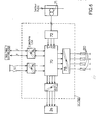
- FIG. 5 shows a variant of FIG. 4, with two identical TBT-A and TBT-B switchboards in parallel supplying two busbars 60 belonging to two outgoing groups A and B.
- the same letters or reference numbers are used to designate identical elements.
- the two processes of fig. 4 are replaced in this application by three methods.
- the architecture of fig. 5 brings up a generator GE which cooperates with two control units UC / GE-A and UC / GE-B to obtain a predetermined availability target.
- the first control unit UC / GE-A in the TGE switchboard is interconnected by link c with the control unit UC / TBT-A.
- the second control unit UC / GE-B of the table TGE is connected by another link c to the control unit UC / TBT-B.
- a bidirectional asynchronous serial link m connects the two monitoring units US / TBT-A and US / TBT-B.
Abstract
Description
L'invention est relative à un système informatique à structure multiprocesseur de commande et de contrôle d'un procédé, comprenant une première unité de commande à microprocesseur,destinéeà envoyer des signaux logiques de commande vers au moins un actionneur, une deuxième unité de surveillance à microprocesseur, et une liaison bidirectionnelle de transmission de données autorisant un dialogue réciproque entre les deux unités. Elle s'applique notamment à la commande d'actionneurs bistables comprenant chacun une bobine d'excitation d'un électro-aimant ou d'un relais provoquant un changement d'état de l'actionneur à chaque impulsion d'excitation appliquée à la bobine.The invention relates to a computer system with a multiprocessor structure for command and control of a process, comprising a first microprocessor control unit, intended to send logic control signals to at least one actuator, a second monitoring unit with microprocessor, and a bidirectional data transmission link allowing reciprocal dialogue between the two units. It applies in particular to the control of bistable actuators each comprising an excitation coil of an electromagnet or of a relay causing a change of state of the actuator at each excitation pulse applied to the coil .
La fonction de l'unité de commande consisté à piloter l'équipement électrique du procédé, c'est-à-dire à envoyer des ordres aux actionneurs dans le but de mettre le procédé dans une configuration permettant d'atteindre l'objectif prédéterminé en matière de disponibilité.L'unité de surveillance sert à diagnostiquer les pannes du système et à réaliser des tests de vérification du bon fonctionnement de l'équipement. Le système informatique peut être connecté à un poste central de surveillance par une liaison bidirectionnelle autorisant une transmission des informations.The function of the control unit consists of controlling the electrical equipment of the process, that is to say of sending orders to the actuators in order to put the process in a configuration making it possible to achieve the predetermined objective by The monitoring unit is used to diagnose system failures and to carry out tests to verify the proper functioning of the equipment. The computer system can be connected to a central monitoring station by a bidirectional link authorizing the transmission of information.
Le problème posé par ce genre de système est la modification possible de l'état du procédé en cas de défaillance de l'une des unités. L'émission intempestive d'une impulsion de commande de l'autre unité risque alors en effet de commander une fausse manoeuvre de l'actionneur et un changement d'état de ce dernier. On ne connaît actuellement aucun dispositif de sécurité autorisant de manière simple la commande sûre d'un procédé qui tient compte de l'état initial de l'actionneur au cours de l'apparition d'une défaillance dans l'une des unités du système informatique. La présente invention a pour but de remédier à ces inconvénients et de permettre la réalisation d'un dispositif de commande sûre et fiable dans lequel la commande du procédé est assurée malgré la panne des fonctions de surveillance, et l'état du procédé n'est pas modifié en cas de panne de son électronique de commande.The problem posed by this kind of system is the possible modification of the state of the process in the event of failure of one of the units. The untimely emission of a command pulse from the other unit then risks in fact commanding a wrong actuation of the actuator and a change of state of the latter. No safety device is currently known which simply authorizes the safe control of a process which takes account of the initial state of the actuator during the appearance of a fault in one of the units of the computer system. . The object of the present invention is to remedy these drawbacks and to allow the production of a safe and reliable control device in which the control of the process is ensured despite the failure of the monitoring functions, and the state of the process is not not modified in case of failure of its control electronics.
L'invention est caractérisée par le fait que le fonctionnement des deux unités de commande et de surveillance est indépendant et que le système comporte de plus une interface de sûreté comprenant un circuit logique combinatoire auquel est injecté un signal logique d'entrée de commande en provenance de la première unité de commande ou de la deuxième unité de surveillance, et des moyens séquentiels de contrôle de l'état de l'actionneur, qui délivrent au circuit logique soit un ordre de validation, soit un ordre d'inhibition pour autoriser ou interdire respectivement la manoeuvre de l'actionneur par l'intermédiaire de l'une des unités de commande ou de surveillance. Il en résulte que les éventuels ordres intempestifs d'origines diverses émis par l'unité de commande ne peuvent pas être appliqués à l'actionneur.The invention is characterized in that the operation of the two control and monitoring units is independent and that the system also comprises a safety interface comprising a combinational logic circuit to which is injected a control input logic signal from of the first control unit or of the second monitoring unit, and of the sequential means of controlling the state of the actuator, which deliver to the logic circuit either an validation order, or an inhibition order to authorize or prohibit respectively actuation of the actuator through one of the control or monitoring units. As a result, any untimely orders of various origins issued by the control unit cannot be applied to the actuator.
L'interface de sûreté est raccordée au bus interne de la deuxième unité de surveillance. Les moyens séquentiels de contrôle comprennent une mémoire d'état dans laquelle est stockée la valeur binaire représentative de l'état de l'actionneur, l'écriture et la lecture de la mémoire d'état s'effectuant par l'intermédiaire du logiciel de l'unité de surveillance.The safety interface is connected to the internal bus of the second monitoring unit. The sequential control means comprise a state memory in which is stored the binary value representative of the state of the actuator, the writing and reading of the state memory being carried out by means of the software of the monitoring unit.
Selon une autre caractéristique de l'invention, l'interface de sûreté comporte une mémoire de commande adressable coopérant avec la deuxième unité de surveillance pour injecter dans le circuit logique un signal de commande calibré destiné à actionner un actionneur prédéterminé après validation préalable de la sortie correspondante de la mémoire d'état. Une source auxiliaire ou redondante sert avantageusement à sauvegarder le contenu de la mémoire d'état et à conserver l'alimentation du circuit logique en cas de défaillance de l'une des unités.According to another characteristic of the invention, the safety interface comprises an addressable control memory cooperating with the second monitoring unit to inject into the logic circuit a calibrated control signal intended to actuate a predetermined actuator after prior validation of the output corresponding from the state memory. An auxiliary or redundant source advantageously serves to save the content of the state memory and to keep the logic circuit supply in the event of a failure of one of the units.
Selon une autre caractéristique de l'invention, le circuit logique de l'interface de sûreté comporte une première porte pilotée par le signal de commande calibré de la mémoire de commande et par le signal logique en provenance de l'unité de commande, et une deuxième porte dont l'une des entrées est connectée à la sortie de la première porte et dont l'autre entrée reçoit l'ordre de validation ou d'inhibition de la mémoire d'état.According to another characteristic of the invention, the logic circuit of the safety interface comprises a first gate controlled by the calibrated control signal from the control memory and by the logic signal from the control unit, and a second door, one of the inputs of which is connected to the output of the first door and the other input of which receives the validation or inhibition order from the state memory.
Chaque actionneur bistable peut être formé par un appareil de coupure fonctionnant en télérupteur. Dans l'état actif, chaque appareil de coupure est normalement fermé par l'intermédiaire de la mémoire de commande de l'unité de surveillance, mais peut être néanmoins délesté et relesté par l'unité de commande grâce à l'ordre de validation délivré par la mémoire d'état au circuit logique. Dans l'état inactif, la mémoire d'état bloque le circuit logique pour interdire toute manoeuvre de l'appareil par l'intermédiaire de l'unité de commande.Each bistable actuator can be formed by a switching device operating as a remote control switch. In the active state, each cut-off device is normally closed via the control unit's control memory, but can nevertheless be unloaded and relested by the control unit thanks to the validation command issued by the state memory to the logic circuit. In the inactive state, the state memory blocks the logic circuit to prohibit any operation of the device via the control unit.
Une première application de l'invention est prévue à titre d'exemple pour le contrôle d'un poste de distribution d'énergie électrique à courant alternatif utilisant deux sources d'alimentation en redondance séquentielle, la première source étant le réseau normal et la deuxième source comprenant un groupe électrogène de secours, le passage d'une source à l'autre s'effectuant au moyen d'un permutateur normal/secours logé dans un tableau à basse tension renfermant un jeu de barres de répartition équipé d'une pluralité de départs utilisateurs protégés par des appareils de coupure. Les informations de délestage et de relestage et les demandes d'arrêt et de marche du groupe électrogène circulent dans une liaison bidirectionnelle agencée entre les deux unités de commande pilotant le groupe électrogène et le tableau basse tension des départs utilisateurs.A first application of the invention is provided by way of example for the control of an AC power distribution station using two power sources in sequential redundancy, the first source being the normal network and the second source comprising a standby generator, the passage from one source to the other being effected by means of a normal / standby permutator housed in a low voltage switchboard containing a set of distribution bars fitted with a plurality of User feeders protected by switching devices. The load shedding and ballast information and the stop and start requests for the generator set circulate in a bidirectional link arranged between the two control units controlling the generator set and the low-voltage switchboard for user feeders.
Une deuxième application de l'invention consiste à répartir les départs utilisateurs en deux groupes en parallèle alimentés par deux tableaux basse tension, renfermant chacun une unité de commande et une unité de surveillance. Le groupe électrogène est piloté par deux unités de commande redondantes reliées chacune par une liaison bidirectionnelle à l'unité de commande correspondante des deux tableaux basse tension. La qualité de service est telle que pour deux départs prioritaires alimentant une structure redondante, l'indisponibilité simultanée des deux départs est inférieure ou égale à 10-6, c'est-à-dire moins de une heure de panne pour une période de 100 années.A second application of the invention consists in dividing the user feeders into two groups in parallel supplied by two low voltage switchboards, each containing a control unit and a monitoring unit. The generator set is controlled by two redundant control units each connected by a bidirectional link to the corresponding control unit of the two low-voltage switchboards. The quality of service is such that for two priority departures supplying a redundant structure, the simultaneous unavailability of the two departures is less than or equal to 10-6, that is to say less than one hour of breakdown for a period of 100 years.
D'autres avantages et caractéristiques ressortiront plus clairement de l'exposé qui va suivre de différents modes de mise en oeuvre de l'invention, donnés à titre d'exemples non limitatifs et représentés aux dessins annexés, dans lesquels :
- - la figure 1 montre schématiquement le système informatique de commande et de contrôle d'un procédé dans lequel intervient l'interface de sure- té selon l'invention;
- - la figure 2 représente le schéma synoptique de l'interface de sûreté servant à commander une pluralité d'actionneurs;
- - la figure 3 est une vue détaillée de l'interface de sûreté de la fi- .
gure 2, associée à une série de quatre actionneurs; - - la figure 4 représente une première application du système informatique selon l'invention, concernant un poste de distribution d'énergie électrique à courant alternatif utilisant deux sources d'alimentation en redondance séquentielle;
- - la figure 5 est une variante de la fig. 4, dans laquelle est installée une redondance des tableaux de distribution;
- - la figure 6 montre une vue synoptique d'une unité de commande d'un tableau à basse tension selon la fig. 4 ou 5.
- -a figure 1 représente schématiquement un
système 10 infor- natique pour le contrôle d'un procédé industriel associé à jescapteurs actionneurs système 10 présente une structure multiprocesseur comprenant ine unité de commande UC couplée avec une unité de surveillance US au moyen d'une première liaison bidirectionnelle 18, notamment une liaison série asynchrone à découplage galvanique. L'unité de commande UC est constituéepar un microprocesseur qui reçoit par l'intermédiaire d'unepremière interface 20 d'entrée, des signaux de mesure en provenance descapteurs 12. L'unité de surveillance US comporte également un microprocesseur qui traite par l'inter- nédiaire d'unedeuxième interface 22 d'entrée les signaux de mesure délivrés par lescapteurs 13. Ces signaux de mesure sont généralement des signaux analogiques transformés dans les interfaces d'entrées 20, 22 en valeurs numériques qui sont comparées par les microprocesseurs respectifs à des valeurs de référence ou de consigne enregistrées dans une mémoire correspondante des unités UC et US.
- - Figure 1 shows schematically the computer system for command and control of a process in which the safety interface according to the invention operates;
- - Figure 2 shows the block diagram of the safety interface used to control a plurality of actuators;
- - Figure 3 is a detailed view of the safety interface of the fi-.
gure 2, associated with a series of four actuators; - - Figure 4 shows a first application of the computer system according to the invention, relating to an AC power distribution station using two power sources in sequential redundancy;
- - Figure 5 is a variant of FIG. 4, in which a redundancy of the switchboards is installed;
- - Figure 6 shows a block view of a control unit of a low voltage switchboard according to fig. 4 or 5.
- FIG. 1 schematically represents a
computer system 10 for controlling an industrial process associated withsensors actuators System 10 has a multiprocessor structure comprising a control unit UC coupled with a US monitoring unit by means of a firstbidirectional link 18, in particular an asynchronous serial link with galvanic decoupling. The control unit UC is constituted by a microprocessor which receives, via afirst input interface 20, measurement signals coming from thesensors 12. The monitoring unit US also includes a microprocessor which processes by the through asecond input interface 22 the measurement signals delivered by thesensors 13. These measurement signals are generally analog signals transformed in theinput interfaces
L'unité de surveillance US peut communiquer au moyen d'une deuxième liaison 24 bidirectionnelle avec un poste central PC de contrôle à distance du système 10. Le poste PC centralise toutes les informations du système 10, notamment les consignes d'exploitation qui peuvent être modifiées à tout moment par l'opérateur. La voie de sortie V1 de l'unité de commande UC délivre directement un signal logique de commande au premier actionneur 14, alors que la commande du deuxième actionneur 16 s'effectue par l'intermédiaire d'une interface de sûreté 26 pilotée à la fois par l'unité de commande UC et par l'unité de surveillance US. L'interface de sûreté 26 est agencée pour assurer la continuité de la transmission des ordres de commande de l'unité de surveillance US vers l'actionneur 16 en cas de défaillance de l'unité de commande UC, et alternativement de l'unité de commande UC vers l'actionneur 16 en cas de panne de l'unité de surveillance US. La voie de sortie V2 de l'unité de commande UC est reliée à l'une des entrées de l'interface 26, et un bus 28 sert de liaison entre l'unité de surveillance US et l'autre entrée de l'interface de sûreté 26.The monitoring unit US can communicate by means of a second
La figure 2 représente le schéma synoptique de l'interface de sûreté 26 conforme à l'invention. Cette interface de sûreté 26 sert à commander une pluralité d'actionneurs 16 bistables comprenant chacun une bobine d'un électro-aimant d'un relais de commande (non représenté), qui provoque un changement d'état de l'actionneur à chaque impulsion d'excitation appliquée à la bobine. Chaque actionneur 16 bistable présente :
- - un état actif "EN EXPLOITATION" dans lequel on autorise sa manoeuvre par l'unité de commande UC,
- - et un état inactif "HORS EXPLOITATION" dans lequel on interdit toute manoeuvre par l'unité de commande UC. L'état de chaque
actionneur 16 est affiché dans une mémoire d'état ME de l'interface desûreté 26 par l'intermédiaire du logiciel de l'unité de surveillance US. La sortie de la mémoire d'état ME est connectée à une première entrée E11 d'un circuit logique 30 combinatoire comprenant une deuxième entrée E22 reliée à la voie de sortie V2 de l'unité de commande UC. Une impulsion de commande en provenance de l'unité de surveillance US peut être appliquée à une troisième entrée E33 du circuit logique 30 par l'intermédiaire d'une mémoire de commande MC. Uneinterfacebus 32 est in- tercaléeentre lebus 28 de l'unité de surveillance US et les entrées des deux mémoires d'état ME et de commande MC. Le circuit logique 30 comporte une pluralité de voies de sorties VS qui transmettent les ordres de commande auxdifférents actionneurs 16, chaque voie étant associée à une bobine d'un actionneur prédéterminé. Des moyens séquentiels de vérification comprenant un registre de lecture LEC coopérant avec l'interfacebus 32 autorisent la relecture par l'unité de surveillance US d'informations en provenance desactionneurs 16. Ces informations sont délivrées par des auxiliaires électriques (non représentés), notamment des contacts ou autres détecteurs de signalisation de l'état desactionneurs 16, puis appliquées au registre de lecture LEC par l'intermédiaire d'un circuit d'isolement et defiltrage 34.
- - an active "OPERATING" state in which it is authorized to be operated by the control unit UC,
- - and an inactive "OUT OF OPERATION" state in which any operation by the UC control unit is prohibited. The state of each actuator 16 is displayed in a state memory ME of the
safety interface 26 by means of the software of the monitoring unit US. The output of the state memory ME is connected to a first input E11 of acombinational logic circuit 30 comprising a second input E22 connected to the output channel V2 of the control unit UC. A control pulse from the monitoring unit US can be applied to a third input E33 of thelogic circuit 30 via a control memory MC. Abus interface 32 is inserted betweenbus 28 of the monitoring unit US and the inputs of the two state memories ME and of control MC. Thelogic circuit 30 comprises a plurality of output channels VS which transmit the control commands to thedifferent actuators 16, each channel being associated with a coil of a predetermined actuator. Sequential verification means comprising a reading register LEC cooperating with thebus interface 32 authorize the re-reading by the monitoring unit US of information coming from theactuators 16. This information is delivered by electrical auxiliaries (not shown), in particular contacts or other signaling detectors tion of the state of theactuators 16, then applied to the read register LEC by means of an isolation andfiltering circuit 34.
Une source auxiliaire d'alimentation AL autonome ou redondante alimente directement la mémoire d'état ME et le circuit logique 30 de commande des actionneurs 16. En cas de défaillance de l'une quelconque des unités de commande UC et de surveillance US, la source AL permet de sauvegarder le contenu de la mémoire d'état ME et de conserver l'alimentation du circuit logique 30.An auxiliary source of autonomous or redundant power supply AL directly supplies the state memory ME and the
La mémoire d'état ME mémorise n bits ou valeurs binaires 1 ou 0 correspondant chacune à l'état des n actionneurs 16. Le bit 1 correspond par exemple à l'état actif "EN EXPL." d'un actionneur 16, tandis que le bit 0 correspond à l'état inactif "HORS EXPL.". La présence du bit 1 à une adresse prédéterminée de la mémoire d'état ME envoie un ordre de validation à l'entrée E11 du circuit logique 30 et autorise la manoeuvre de l'actionneur 16 adressé, l'ordre de commande pouvant venir soit de l'unité de commande UC par la voie V2, soit de l'unité de surveillance US par l'intermédiaire de la mémoire de commande MC. La présence du bit 0 à une adresse prédéterminée de la mémoire d'état ME engendre un ordre d'inhibition vers le circuit logique 30, et condamne la manoeuvre de l'actionneur 16 correspondant. Le fonctionnement précis du dispositif de la fig. 2 sera mieux compris par la suite à l'aide du schéma détaillé de la figure 3.The state memory ME stores n bits or
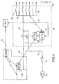
Selon la figure 3, l'interface de sûreté 26 commande une série de quatre actionneurs 16 formés à titre d'exemple par des appareils de coupure de courant télécommandés D1, D2, D3, D4, insérés dans les départs d'un réseau de distribution basse tension. La structure du mécanisme d'un tel appareil de coupure est décrite en détail dans la demande de brevet français ? 82 18551 du 3-11-1982 de la demanderesse, le mécanisme autorisant une commande à distance de fermeture et/ou d'ouverture, et une commande locale de déclenchement sur défaut. Le circuit électronique d'alimentation de l'appareil de coupure susmentionné fait l'objet de la demande de brevet français N° 82 20111 du 29-11-1982 de la demanderesse.According to FIG. 3, the
A chaque appareil de coupure D1, D2, D3, D4 est associé un système de contacts auxiliaires CAO d'ouverture, CAF de fermeture et CD de défaut, destiné à signaler l'état de l'appareil au registre de lecture LEC. Certains départs du réseau sont prioritaires et les autres départs sont non prioritaires, et les quatre appareils D1, D2, D3, D4 appartiennent à une série de même priorité. La voie de sortie V2 de l'unité de commande UC est composée à cet effet d'une ligne prioritaire LP et d'une ligne non priorité LNP destinées chacune à envoyer des ordres de commande, notamment de délestage et de relestage à une même série d'appareils. Un sélect eur de priorité SP permet de choisir le type de priorité pour une interface de sûreté 26 prédéterminée. Dans l'exemple de la figure 3, le sélecteur SP est commuté sur la ligne prioritaire LP de l'unité de commande UC, et l'interface 26 assure la commande des quatre appareils D1, D2, D3, D4 d'une même série de lestage associée à quatre départs prioritaires. La carte de l'interface de sûreté 26 peut bien entendu commander un nombre différent d'appareils de coupure selon la structure du réseau. La voie de sortie V2 de l'unité de commande UC peut également comporter une pluralité de lignes à degré de priorité variable; le nombre de plots du sélecteur de priorité SP correspond alors au nombre de lignes de la voie V2. Les deux mémoires d'état ME et de commande MC sont des mémoires adressables.Each breaking device D1, D2, D3, D4 is associated with a system of auxiliary contacts CAD opening, CAF closing and fault CD, intended to signal the state of the device to the LEC reading register. Some network departures have priority and other departures have non-priority, and the four devices D1, D2, D3, D4 belong to a series of the same priority. The output channel V2 of the control unit UC is composed for this purpose of a priority line LP and a non-priority line LNP each intended to send control orders, in particular load shedding and relesting to the same series of devices. A priority selector SP makes it possible to choose the type of priority for a
Le bus 28 de l'unité de surveillance US communique avec l'interface bus 32 au moyen d'un bus données BD, et avec un sélecteur d'adresse SA de la carte et avec un sélecteur de fonction SF d'écriture et de lecture respectivement par des bus d'adresse BA et d'ordre BO. Le sélecteur d'adresse SA coopère avec un chien de garde CG dont l'intervention sert à bloquer dans l'interface 32 la fonction d'écriture en provenance du microprocesseur de l'unité de surveillance US. Il en résulte alors un blocage simultané d'écriture de la mémoire d'état ME et de la mémoire de commande MC pour éviter toute émission intempestive d'ordres en direction des appareils D1 à D4.The
Chaque appareil de coupure D1, D2, D3, D4 est bistable et fonctionne en télérupteur, c'est-à-dire que chaque impulsion d'excitation appliquée à sa bobine de commande par le circuit logique 30 provoque un changement d'état du contact mobile, entrainé soit en position stable de fermeture, soit en position stable d'ouverture. Lorsqu'un appareil de coupure D1 à D4 se trouve dans l'état inactif "HORS EXPL.", son contact correspondant est verrouillé par l'interface 26 en position ouvert, étant donné que son état (bit 0) est inscrit dans la mémoire d'état ME ce qui interdit toute manoeuvre par l'unité de commande UC. Dans l'état actif "EN EXPL.", chaque appareil de coupure D1 à D4 est normalement fermé par l'intermédiaire de l'unité de surveillance US, mais peut néanmoins être délesté et relesté par l'unité de commande UC grâce à la validation confirmée par la mémoire d'état ME chargée par le bit 1 à l'adresse correspondante.Each breaking device D1, D2, D3, D4 is bistable and operates as a remote control switch, that is to say that each excitation pulse applied to its control coil by the
Pour des raisons de clarté du dessin de la figure 3, seule la commande de l'appareil de coupure D1 a été représentée. La voie de sortie VS1 du circuit logique 30 est en fait reliée au moyen de commande K du circuit décrit dans la demande de brevet français N° 82 20111 précitée.For reasons of clarity of the drawing in FIG. 3, only the control of the switching device D1 has been shown. The output channel VS1 of the
La mémoire d'état ME mémorise quatre bits correspondant chacun à l'état (actif ou inactif) des quatre appareils de coupure D1 à D4. La sortie S1 de la mémoire d'état ME est affectée à l'état de l'appareil D1 et est connectée à une première entrée d'une porte ET 36 du circuit logique 30. L'autre entrée de la porte ET 36 est pilotée par une porte OU 37 pouvant être commandée par deux impulsions en provenance de l'unité de commande UC et de l'unité de surveillance US. L'impulsion de cette dernière est délivrée par la sortie S1 de la mémoire de commande MC. Un circuit adaptateur 38 est interconnecté entre la sortie de la porte ET 36 et l'appareil de coupure D1. La sortie S1 de la mémoire d'état ME applique à la porte ET 36 un ordre de validation (bit 1) ou un ordre d'inhibition (bit 0) selon l'état "EN EXPL." ou "HORS EXPL." de l'appareil de coupure D1.The state memory ME stores four bits each corresponding to the state (active or inactive) of the four switching devices D1 to D4. The output S1 of the state memory ME is assigned to the state of the device D1 and is connected to a first input of an AND
La source d'alimentation de la mémoire d'état ME et du circuit logique 30 est double et résulte de l'alimentation commune à l'unité de surveillance US et à l'unité de commande UC. Un convertisseur 40 continu/continu isole galva- niquement la tension de 5V de l'unité de commande UC par rapport à l'une des entrées d'une porte OU 42, dont l'autre entrée est reliée à la tension de 5 V de l'unité de surveillance US. La sortie de la porte OU 42 sert à alimenter la mémoire d'état ME et le circuit logique 30. L'alimentation est ainsi conservée en cas de panne de l'une des unités UC ou US, et l'état des appareils D1 à D4 est sauvegardé.The power source of the state memory ME and of the
Le microprocesseur utilisé dans l'unité de surveillance US est le 68000 de MOTOROLA, et celui de l'unité de commande UC est le 68705 de MOTOROLA.The microprocessor used in the US monitoring unit is the 68000 from MOTOROLA, and that of the UC control unit is the 68705 from MOTOROLA.
Le fonctionnement du dispositif représenté à la figure 3 est le suivant :The operation of the device shown in Figure 3 is as follows:
En partant de la position initiale OUVERT de l'appareil de coupure D1, la mémoire d'état ME doit être chargée par le bit 1 correspondant à l'état actif "EN EXPL." de l'appareil D1. Ce processus de chargement de la mémoire d'état ME est piloté par le logiciel de l'unité de surveillance US :
- - apparition en écriture (ECR) de l'adresse de la carte et l'adresse de la mémoire d'état ME (sortie S1) sur le bus adresse BA,
- - apparition du
bit 1 sur le bus de données BD - - apparition de l'ordre d'écriture (ECR) sur le bus d'ordre BO qui permet de charger la mémoire d'état ME, dont la sortie S1 applique un ordre de validation à la
porte ET 36.
- - appearance in writing (ECR) of the address of the card and the address of the state memory ME (output S1) on the address bus BA,
- - appearance of
bit 1 on the BD data bus - - appearance of the write order (ECR) on the order bus BO which makes it possible to load the state memory ME, whose output S1 applies a validation order to the AND
gate 36.
A partir de cet instant intervient l'émission de l'ordre de fermeture par la sortie S1 de la mémoire de commande MC, cette dernière étant sélectionnée en écriture d'une manière similaire à celle décrite ci-dessus pour le processus de chargement de la mémoire d'état ME. Le bit 1 est gravé dans la mémoire de commande MC pendant une durée prédéterminée (par exemple 50 ms) et il en résulte une impulsion calibrée qui traverse la porte OU 37 et la porte ET 36 de manière à actionner l'appareil D1. Ce dernier change d'état et se ferme.From this instant, the closing order is sent by the output S1 of the control memory MC, the latter being selected in writing in a manner similar to that described above for the process of loading the state memory ME.
La position réelle de l'appareil D1 peut être vérifiée au moyen du registre de lecture LEC dont l'entrée E1 est en liaison avec les contacts auxiliaires CAO et CAF de l'appareil D1. L'accès au registre de lecture LEC s'opère au moyen de l'unité de surveillance US :
- - affichage de l'adresse du registre LEC (entrée E1) sur le bus adresse BA,
- - émission de l'ordre de LECTURE sur le bus ordre BO,
- - apparition sur le bus données BD des états des contacts auxiliaires CAO, CAF.
- - display of the address of the LEC register (entry E1) on the BA address bus,
- - transmission of the READ command on the BO command bus,
- - appearance on the data bus BD of the states of the auxiliary contacts CAO, CAF.
La fermeture des autres appareils D2, D3, D4 s'effectue d'une manière similaire à celle de D1 en utilisant les sorties S2, S3, S4 des mémoires d'état ME et de commande MC.The other devices D2, D3, D4 are closed in a similar way to that of D1 using the outputs S2, S3, S4 of the state memories ME and of control MC.
La procédure est absolument identique puisque l'appareil D1 fonctionne en télérupteur. Après émission de l'impulsion calibrée par la sortie S1 de la mémoire de commande MC, l'appareil D1 s'ouvre. L'unité de surveillance US charge ensuite le bit 0 dans la mémoire d'état ME, ce qui correspond à l'état inactif "HORS EXPL. de l'appareil D1. La sortie S1 de la mémoire d'état ME applique ensuite un ordre d'inhibition à la porte ET 36, ce qui interdit toute commande ultérieure de D1 en provenance de l'unité de commande UC. D1 se trouve ainsi verrouillé en position ouvert.The procedure is absolutely identical since the D1 device operates as a remote control switch. After emission of the pulse calibrated by the output S1 of the control memory MC, the device D1 opens. The monitoring unit US then loads bit 0 in the state memory ME, which corresponds to the inactive state "OUT OF EXPL. Of the device D1. The output S1 of the state memory ME then applies a inhibit command at the AND
L'état des appareils de coupure D1 à D4 associés à l'interface de sûreté 26 est affiché initialement dans la mémoire d'état ME par l'unité de surveillance US.The state of the breaking devices D1 to D4 associated with the
Le signal de commande d'ouverture (délestage) délivré par la ligne LP de l'unité de commande UC est appliqué à la porte OU 37 associée à chaque appareil de coupure D1, D2, D3, D4. La porte ET 36 correspondante du circuit logique 30 assure le blocage ou le passage du signal de commande en provenance de l'unité de commande UC selon l'état de la sortie S1 à S4 correspondante de la mémoire d'état ME. A titre d'exemple, si les sorties S1 et S3 de la mémoire d'état ME se trouvent au niveau 1 correspondant à l'état "EN EXPL." des appareils D1 et D3, alors que les deux sorties S2 et S4 sont à un niveau 0 correspondant à un état "HORS EXPL." des appareils D2 et D4, le circuit logique 30 ne laissera passer que les deux signaux de commande en direction des appareils D1 et D3. Les quatre portes ET 36 du circuit logique 30 reçoivent deux ordres de validation des sorties S1 et S3 et deux ordres d'inhibition des deux autres sorties S2 et S4 de la mémoire d'état ME.The opening control signal (load shedding) delivered by the line LP of the control unit UC is applied to the
Le fonctionnement est similaire à celui décrit précédemment. Le circuit logique 30 laisse passer ou bloque le signal de commande de fermeture (relestage) en provenance de l'unité de commande UC selon le niveau (bit 1 = validation, bit 0 = inhibition) des sorties S1 à S4 de la mémoire d'état ME.The operation is similar to that described above. The
La présence de cette mémoire d'état ME pilotée par l'unité de surveillance US, permet d'éviter des fermetures intempestives des appareils D1 à D4 lors des manoeuvres de délestage et de relestage. Le contenu de la mémoire d'état ME peut être lu par l'unité de surveillance US lors d'une procédure de contrôle. On remarque que la manoeuvre des appareils de coupure D1 à D4 par l'unité de commande UC est tributaire de leurs états affichés dans la mémoire d'état ME par l'unité de surveillance US. La manoeuvre est autorisée lorsque l'appareil se trouve dans l'état "EN EXPL.". Si l'appareil est dans l'état "NON EXPL.", on interdit toute manoeuvre par l'unité de commande UC. En cas de panne de l'unité de surveillance US, le contenu de la mémoire d'état ME est sauvegardé, et les appareils D1 à D4 dans l'état "EN EXPL." peuvent être manoeuvres par l'unité de commande UC.The presence of this state memory ME controlled by the monitoring unit US, makes it possible to avoid untimely closings of the devices D1 to D4 during the load shedding and relesting operations. The content of the state memory ME can be read by the monitoring unit US during a control procedure. Note that the operation of the cut-off devices D1 to D4 by the control unit UC is dependent on their states displayed in the state memory ME by the monitoring unit US. The operation is authorized when the device is in the "EXPL." State. If the device is in the "NON EXPL." State, any operation by the UC control unit is prohibited. In the event of failure of the monitoring unit US, the content of the state memory ME is saved, and the devices D1 to D4 in the state "IN EXPL." can be operated by the control unit UC.
En cas de panne de l'unité de commande UC, chaque appareil D1 à D4 peut être manoeuvré individuellement par l'unité de surveillance US.In the event of failure of the control unit UC, each device D1 to D4 can be operated individually by the monitoring unit US.
La figure 4 représente une première application du système informatique 10 décrit aux figures 1 à 3. Elle concerne un poste de distribution 50 d'énergie électrique à courant alternatif monophasé ou triphasé utilisant deux sources d'alimentation en redondance séquentielle :
- - le réseau normal d'alimentation du poste par l'intermédiaire d'un transformateur MT/
BT 52 et d'un disjoncteur 54 de protection; - - et un groupe électrogène GE de secours comprenant un alternateur entraîné par un moteur à combustion interne.
- - the normal supply network of the substation via an MV /
LV transformer 52 and aprotection circuit breaker 54; - - and a standby GE generator comprising an alternator driven by an internal combustion engine.
Le disjoncteur 54 et la sortie de l'alternateur du groupe GE sont reliés respectivement par des conducteurs 56, 58 à un permutateur PN1, PS1 ou inverseur normal/secours en liaison avec un jeu de barres 60 de répartition, ce dernier étant équipé d'une pluralité de départs utilisateurs protégés et commandés par des appareils de coupure D1 à Dn du type décrit à la fig. 3. On distingue des départs prioritaires, semi-prioritaires et non prioritaires.The
Le permutateur PN1, PS1 normal/secours et les appareils de coupure D1 à Dn sont logés dans un tableau basse tension TBT piloté par un système informatique 10 comprenant une unité de commande UC/TBT et une unité de surveillance US/TBT équipée d'une interface de sûreté 26 décrit en référence à la fig. 3. L'unité de commande UC comprend une première sortie qui contrôle directement le permutateur PN1, PS1, et une deuxième sortie, assimilable à la voie V2 de la fig. 3, qui pilote la manoeuvre des appareils D1 à Dn par l'intermédiaire d'une ou de plusieurs interfaces de sûreté 26. Le tableau TBT renferme également les capteurs nécessaires à la surveillance et au comptage d'énergie.The permutator PN1, normal / backup PS1 and the cut-off devices D1 to Dn are housed in a low-voltage switchgear TBT controlled by a
Le groupe électrogène GE de secours est installé dans un tableau TGE qui renferme de plus les protections de l'alternateur, les actionneurs et les capteurs des équipements électriques et électroniques, une unité de commande UC/GE et une unité de surveillance US/GE. Le groupe GE et son environnement électronique du tableau TGE sont totalement autonomes.The standby GE generator is installed in a TGE switchboard which also contains the protections for the alternator, the actuators and sensors for the electrical and electronic equipment, a UC / GE control unit and a US / GE monitoring unit. The GE group and its electronic environment on the TGE switchboard are completely autonomous.
Différentes liaisons relient entre eux les différents éléments des procédés :Different links connect the different process elements to each other:
- - liaison a bidirectionnelle entre l'unité de surveillance US/GE et le groupe GE;- bidirectional link between the US / GE surveillance unit and the GE group;
-
- liaison 1 bidirectionnelle entre l'unité de commande UC/GE et le groupe GE;-
bidirectional link 1 between the UC / GE control unit and the GE group; - - liaison b bidirectionnelle transmettant les informations des capteurs servant à la commande du groupe GE vers l'unité de surveillance US/GE, ainsi que les états internes et les résultats de tests de l'unité de commande UC/GE. En retour elles transmettent les ordres d'exploitation en provenance de l'unité de surveillance US/GE;- bidirectional link b transmitting the information from the sensors used to control the GE group to the US / GE monitoring unit, as well as the internal states and test results of the UC / GE control unit. In return, they transmit the operating orders from the US / GE surveillance unit;
- - liaison c bidirectionnelle pour l'échange d'informations entre les deux unités de commande UC/GE et UC/TBT. Dans le sens GE vers TBT circulent les informations de délestage et de relestage du groupe GE. Dans le sens TBT vers GE circulent les demandes d'arrêt et de marche du groupe GE.- bidirectional link c for the exchange of information between the two control units UC / GE and UC / TBT. In the direction GE towards TBT circulate the load shedding and relest information of the GE group. In the TBT to GE direction, stop and start requests from the GE group circulate.
-
- liaison d bidirectionnelle pour la mesure des tensions sur le jeu de barres 60 et la commande des bobines du permutateur PS1, PN1.- bidirectional link for the measurement of the voltages on the
busbar 60 and the control of the coils of the permutator PS1, PN1. - - liaison e bidirectionnelle pour l'échange d'informations entre les unités de commande UC/TBT et de surveillance US/TBT (consignes d'exploitation dans le sens US/TBT vers UC/TBT et états internes et comptes-rendus d'auto-tests dans le sens UC/TBT vers US/TBT).- bidirectional link for the exchange of information between the UC / TBT control units and the US / TBT monitoring units (operating instructions in the US / TBT direction to UC / TBT and internal states and auto reports -tests in the direction UC / TBT towards US / TBT).
-
- liaison f unidirectionnelle concernant les informations nécessaires au comptage d'énergie et à la surveillance du jeu de barres 60.- unidirectional link f concerning information necessary for energy metering and
busbar monitoring 60. -
- liaison g (assimilable à la voie V2 de la fig. 3) entre l'unité de commande UC/TBT et l'interface de commande 26 pour piloter les lestages et délestages des appareils D1 à Dn.- link g (similar to channel V2 in fig. 3) between the UC / TBT control unit and the
control interface 26 to control ballast and load shedding of devices D1 to Dn. -
- liaison h bidirectionnelle reliant tous les appareils D1 à Dn à l'interface 26 de l'unité de surveillance US/TBT.- bidirectional link h connecting all the devices D1 to Dn to the
interface 26 of the US / TBT monitoring unit. - - liaison 24 série synchrone bidirectionnelle reliant chaque unité de surveillance US/TBT, US/GE au poste central PC. Sur ces lignes circulent les messages d'exploitation et les messages d'alarme.- 24 bidirectional synchronous serial link connecting each US / TBT, US / GE monitoring unit to the central PC station. On these lines circulate operating messages and alarm messages.
La figure 5 montre une variante de la fig. 4, avec deux tableaux TBT-A et TBT-B identiques en parallèle alimentant deux jeux de barres 60 appartenant à deux groupes A et B de départs.Les mêmes lettres ou numéros de repères sont utilisés pour désigner des éléments identiques. Les deux procédés de la fig. 4 sont remplacés dans cette application par trois procédés. L'architecture de la fig. 5 fait apparaÎtre un groupe électrogène GE coopérant avec deux unités de commande UC/GE-A et UC/GE-B permettant d'obtenir un objectif de disponibilité prédéterminé. La première unité de commande UC/GE-A du tableau TGE est interconnectée par la liaison c avec l'unité de commande UC/TBT-A. La deuxième unité de commande UC/GE-B du tableau TGE est reliée par une autre liaison c à l'unité de commande UC/TBT-B. Une liaison m série asynchrone bidirectionnelle relie les deux unités de surveillance US/TBT-A et US/TBT-B.FIG. 5 shows a variant of FIG. 4, with two identical TBT-A and TBT-B switchboards in parallel supplying two
Le schéma synoptique de l'unité de commande UC/TBT des tableaux basse tension utilisée dans les dispositifs des fig. 4 et 5 est représenté à la fig. 6. Le micro-contrôleur 70 intègre une unité centrale, une mémoire RAM et REPROM, un compteur, un multiplexeur et un convertisseur analogique numérique CAN. Le microcontrôleur 70 est connecté par l'intermédiaire des capteurs de potentiel 71 d'une interface 72 d'entrée de mesure des tensions du secteur public qui assure l'isolement galvanique entre le secteur et le sys- ,tème, l'adaptation du niveau de tension et la conversion alternatif/continu. L'unité de commande UC/TBT comporte de plus :
- - deux jonctions 74 à liaisons (e et c) série asynchrone entre le micro-contrôleur 70 et l'unité de surveillance US/TBT d'une part, et l'unité de commande UC/GE d'autre part. Ces deux jonctions autorisent la réception depuis l'US/TBT des ordres d'exploitation, et l'émission vers l'US/TBT des états internes de l'UC:TBT.
- -
une interface 76 ENTREES TOR logiques reliée àces capteurs 12. - -
une première interface 78 SORTIES logiques pour la commande des bobines 80 du permutateur correspondant PS1, PN1; PS2, PN2. - -
une deuxième interface 82 SORTIES logiques reliée à l'interface de sûreté 26 selon l'invention, pour la commande de relestage et de délestage.
- - two
junctions 74 with asynchronous serial links (e and c) between themicrocontroller 70 and the US / TBT monitoring unit on the one hand, and the UC / GE control unit on the other hand. These two junctions authorize the reception from the US / TBT of the operating orders, and the emission towards the US / TBT of the internal states of the CPU: TBT. - - an
interface 76 digital TOR INPUTS connected to thesesensors 12. - - a
first interface 78 logic OUTPUTS for controlling thecoils 80 of the corresponding permutator PS1, PN1; PS2, PN2. - - A
second interface 82 logic OUTPUTS connected to thesafety interface 26 according to the invention, for the control of load shedding and load shedding.
Selon le dispositif de la fig. 5, l'indisponibilité simultanée de deux départs prioritaires à cause d'une défaillance du matériel est inférieure à 10-6, c'est-à-dire moins de 1 heure de panne pour une période de 100-années. Ce dispositif permet de produire et de distribuer l'énergie électrique en cas de disparition du secteur public avec le minimum d'équipements en bon fonctionnement qui peuvent se réduire à :
- - groupe de secours GE
- - une unité de commande UC/GE du groupe secours et l'unité de commande UC/TBT du tableau basse tension qui lui est associée.
- - GE rescue group
- - a UC / GE control unit of the backup group and the unit control unit UC / TBT of the low voltage switchboard associated with it.
L'invention n'est bien entendu nullement limitée aux modes de mise en oeuvre plus particulièrement décrits et représentés aux dessins annexés, mais elle s'étend bien au con- .traire à toute variante restant dans le cadre des équivalences.The invention is of course by no means limited to the modes of implementation more particularly described and represented in the appended drawings, but it extends well to the contrary to any variant remaining within the framework of equivalences.
Claims (10)
Applications Claiming Priority (2)
| Application Number | Priority Date | Filing Date | Title |
|---|---|---|---|
| FR8404182 | 1984-03-15 | ||
| FR8404182A FR2561413B1 (en) | 1984-03-15 | 1984-03-15 | COMPUTER SYSTEM WITH MULTIPROCESSOR STRUCTURE FOR COMMAND AND CONTROL OF A PROCESS |
Publications (1)
| Publication Number | Publication Date |
|---|---|
| EP0155213A1 true EP0155213A1 (en) | 1985-09-18 |
Family
ID=9302157
Family Applications (1)
| Application Number | Title | Priority Date | Filing Date |
|---|---|---|---|
| EP85400404A Withdrawn EP0155213A1 (en) | 1984-03-15 | 1985-03-04 | Information system of a multiprocessor structure for the control of a process |
Country Status (2)
| Country | Link |
|---|---|
| EP (1) | EP0155213A1 (en) |
| FR (1) | FR2561413B1 (en) |
Cited By (10)
| Publication number | Priority date | Publication date | Assignee | Title |
|---|---|---|---|---|
| FR2610120A1 (en) * | 1987-01-26 | 1988-07-29 | Merlin Gerin | CONTROL AND PROTECTION ASSEMBLY CONNECTING A LOCAL COMMUNICATION NETWORK TO AN INDUSTRIAL PROCESS |
| EP0276937A1 (en) * | 1987-01-29 | 1988-08-03 | British Gas plc | Safety monitor |
| FR2651890A1 (en) * | 1989-09-11 | 1991-03-15 | Siemens Bendix Automotive Elec | DEVICE FOR DETECTION AND DISCRIMINATION OF OPERATING FAULTS OF AN ELECTRICAL SUPPLY CIRCUIT. |
| FR2761173A1 (en) * | 1997-03-19 | 1998-09-25 | Schneider Automation | PROGRAMMABLE PLC MODULE |
| EP0915400A2 (en) * | 1997-11-06 | 1999-05-12 | Siemens Aktiengesellschaft | Peripheral control unit for a process control system |
| WO2000028390A1 (en) * | 1998-11-09 | 2000-05-18 | Siemens Aktiengesellschaft | Method for monitoring an output unit |
| WO2002100041A1 (en) * | 2001-06-06 | 2002-12-12 | Kvaser Consultant Ab | Arrangement and method for system of locally deployed module units, and contact unit for connection of such a module unit |
| WO2005003869A1 (en) * | 2003-07-04 | 2005-01-13 | Pilz Gmbh & Co. Kg | Device and method for automatically controlling a technical system operation |
| CN104020685A (en) * | 2013-02-28 | 2014-09-03 | 发那科株式会社 | Control system equipped with detachable control panel |
| EP1589386B1 (en) | 2004-04-16 | 2018-01-10 | Sick Ag | Process control system |
Families Citing this family (1)
| Publication number | Priority date | Publication date | Assignee | Title |
|---|---|---|---|---|
| FR2895533B1 (en) * | 2005-12-26 | 2008-05-09 | Brandt Ind Sas | DEVICE FOR ELECTRONIC CONTROL OF A DOMESTIC APPLIANCE |
Citations (2)
| Publication number | Priority date | Publication date | Assignee | Title |
|---|---|---|---|---|
| GB2057207A (en) * | 1979-08-27 | 1981-03-25 | Gen Electric | Relay switching apparatus |
| US4365297A (en) * | 1980-12-29 | 1982-12-21 | Forney Engineering Company | Industrial control system with distributed computer implemented logic |
-
1984
- 1984-03-15 FR FR8404182A patent/FR2561413B1/en not_active Expired
-
1985
- 1985-03-04 EP EP85400404A patent/EP0155213A1/en not_active Withdrawn
Patent Citations (2)
| Publication number | Priority date | Publication date | Assignee | Title |
|---|---|---|---|---|
| GB2057207A (en) * | 1979-08-27 | 1981-03-25 | Gen Electric | Relay switching apparatus |
| US4365297A (en) * | 1980-12-29 | 1982-12-21 | Forney Engineering Company | Industrial control system with distributed computer implemented logic |
Cited By (19)
| Publication number | Priority date | Publication date | Assignee | Title |
|---|---|---|---|---|
| FR2610120A1 (en) * | 1987-01-26 | 1988-07-29 | Merlin Gerin | CONTROL AND PROTECTION ASSEMBLY CONNECTING A LOCAL COMMUNICATION NETWORK TO AN INDUSTRIAL PROCESS |
| EP0278802A1 (en) * | 1987-01-26 | 1988-08-17 | Merlin Gerin | Control and protection assembly linking a local communication network to an industrial process |
| EP0276937A1 (en) * | 1987-01-29 | 1988-08-03 | British Gas plc | Safety monitor |
| GB2200476B (en) * | 1987-01-29 | 1991-02-06 | British Gas Plc | Monitor system |
| US5063527A (en) * | 1987-01-29 | 1991-11-05 | British Gas Plc | Monitor system |
| FR2651890A1 (en) * | 1989-09-11 | 1991-03-15 | Siemens Bendix Automotive Elec | DEVICE FOR DETECTION AND DISCRIMINATION OF OPERATING FAULTS OF AN ELECTRICAL SUPPLY CIRCUIT. |
| EP0418665A1 (en) * | 1989-09-11 | 1991-03-27 | Siemens Aktiengesellschaft | Device for the detection and discrimination of functional faults in an electrical power supply circuit |
| US5161112A (en) * | 1989-09-11 | 1992-11-03 | Siemens Aktiengesellschaft | Device for sensing and discriminating operational faults in an electrical power supply |
| FR2761173A1 (en) * | 1997-03-19 | 1998-09-25 | Schneider Automation | PROGRAMMABLE PLC MODULE |
| EP0915400A2 (en) * | 1997-11-06 | 1999-05-12 | Siemens Aktiengesellschaft | Peripheral control unit for a process control system |
| EP0915400A3 (en) * | 1997-11-06 | 2000-09-13 | Siemens Aktiengesellschaft | Peripheral control unit for a process control system |
| WO2000028390A1 (en) * | 1998-11-09 | 2000-05-18 | Siemens Aktiengesellschaft | Method for monitoring an output unit |
| US6650950B2 (en) | 1998-11-09 | 2003-11-18 | Siemens Aktiengellschaft | Method for monitoring an output unit |
| WO2002100041A1 (en) * | 2001-06-06 | 2002-12-12 | Kvaser Consultant Ab | Arrangement and method for system of locally deployed module units, and contact unit for connection of such a module unit |
| US7882275B2 (en) | 2001-06-06 | 2011-02-01 | Xinshu Management, L.L.C. | Arrangement and method for system of locally deployed module units, and contact unit for connection of such a module unit |
| US8195841B2 (en) | 2001-06-06 | 2012-06-05 | Xinshu Management L.L.C. | Communicating with a first and second protocol |
| WO2005003869A1 (en) * | 2003-07-04 | 2005-01-13 | Pilz Gmbh & Co. Kg | Device and method for automatically controlling a technical system operation |
| EP1589386B1 (en) | 2004-04-16 | 2018-01-10 | Sick Ag | Process control system |
| CN104020685A (en) * | 2013-02-28 | 2014-09-03 | 发那科株式会社 | Control system equipped with detachable control panel |
Also Published As
| Publication number | Publication date |
|---|---|
| FR2561413B1 (en) | 1989-04-14 |
| FR2561413A1 (en) | 1985-09-20 |
Similar Documents
| Publication | Publication Date | Title |
|---|---|---|
| FR2503922A1 (en) | CUTTING INSTALLATION OF A NUCLEAR REACTOR | |
| US6892145B2 (en) | Method and system for conditionally triggered system data capture | |
| EP0155213A1 (en) | Information system of a multiprocessor structure for the control of a process | |
| US9941739B2 (en) | Process bus associated protective control system, merging unit, and calculation device | |
| FR2508246A1 (en) | ELECTRICAL INSTALLATION WITH CONTROL UNIT ACCEPTING ERRORS | |
| EP0531230A1 (en) | Electrical energy distributing device with monitoring of isolation | |
| EP1307804A2 (en) | Maintenance system for an equipment set | |
| FR2610120A1 (en) | CONTROL AND PROTECTION ASSEMBLY CONNECTING A LOCAL COMMUNICATION NETWORK TO AN INDUSTRIAL PROCESS | |
| EP3390133A1 (en) | Safety module, and charging station provided with a safety module | |
| CA2080522C (en) | Apparatus for the determination of the state of an instrument, especially the open and the closed state of an electrical appliance with ancillary contacts | |
| EP0232636B1 (en) | Device for assisting in the maintenance of an electromechanical installation which includes automatic means for checking and control | |
| AU2010202580B2 (en) | Device and method for signalling electric faults, unit and electric panel comprising such a device | |
| EP0704952B2 (en) | Self-monitoring circuit, especially for electrical apparatus and in particular for an SF6 high-voltage circuit breaker | |
| US6600242B1 (en) | Method and apparatus for determining switch status | |
| FR2701129A1 (en) | Safety power interface. | |
| RU2570572C1 (en) | Microprocessor control panel | |
| EP0337235B1 (en) | Appliance for testing electrical protection relays during operation | |
| FR2580124A1 (en) | ||
| CN101726704A (en) | Fault replaying method based on micro-processor based protective relay device | |
| EP2999084B1 (en) | Electrical interconnection device for source inverter, and source inverter comprising such a device | |
| FR2682201A1 (en) | METHOD FOR THE TEMPORAL DISCRIMINATION OF FAULTS IN A HIERARCHIZED DATA PROCESSING SYSTEM, AND HIERARCHED DATA PROCESSING SYSTEM SUITABLE FOR ITS IMPLEMENTATION. | |
| US5878375A (en) | Data transfer switching device and method of use therefore | |
| JPS605918B2 (en) | monitoring device | |
| US20220368125A1 (en) | Output contact failure monitor for protection relays in electric power systems | |
| SU1149349A1 (en) | Device for emergency limiting of power output of electric power plant |
Legal Events
| Date | Code | Title | Description |
|---|---|---|---|
| PUAI | Public reference made under article 153(3) epc to a published international application that has entered the european phase |
Free format text: ORIGINAL CODE: 0009012 |
|
| AK | Designated contracting states |
Designated state(s): AT BE CH DE GB IT LI NL SE |
|
| 17P | Request for examination filed |
Effective date: 19851219 |
|
| 17Q | First examination report despatched |
Effective date: 19870518 |
|
| STAA | Information on the status of an ep patent application or granted ep patent |
Free format text: STATUS: THE APPLICATION HAS BEEN WITHDRAWN |
|
| 18W | Application withdrawn |
Withdrawal date: 19870905 |
|
| RIN1 | Information on inventor provided before grant (corrected) |
Inventor name: FRANCON, CLAUDE |