EP0155084A1 - Device for measuring the shape of a three-dimensional object - Google Patents
Device for measuring the shape of a three-dimensional object Download PDFInfo
- Publication number
- EP0155084A1 EP0155084A1 EP85300949A EP85300949A EP0155084A1 EP 0155084 A1 EP0155084 A1 EP 0155084A1 EP 85300949 A EP85300949 A EP 85300949A EP 85300949 A EP85300949 A EP 85300949A EP 0155084 A1 EP0155084 A1 EP 0155084A1
- Authority
- EP
- European Patent Office
- Prior art keywords
- probe
- dimensional object
- movable arm
- shape
- angle
- Prior art date
- Legal status (The legal status is an assumption and is not a legal conclusion. Google has not performed a legal analysis and makes no representation as to the accuracy of the status listed.)
- Granted
Links
Images


Classifications
-
- B—PERFORMING OPERATIONS; TRANSPORTING
- B25—HAND TOOLS; PORTABLE POWER-DRIVEN TOOLS; MANIPULATORS
- B25J—MANIPULATORS; CHAMBERS PROVIDED WITH MANIPULATION DEVICES
- B25J17/00—Joints
- B25J17/02—Wrist joints
- B25J17/0258—Two-dimensional joints
- B25J17/0275—Universal joints, e.g. Hooke, Cardan, ball joints
-
- B—PERFORMING OPERATIONS; TRANSPORTING
- B25—HAND TOOLS; PORTABLE POWER-DRIVEN TOOLS; MANIPULATORS
- B25J—MANIPULATORS; CHAMBERS PROVIDED WITH MANIPULATION DEVICES
- B25J9/00—Programme-controlled manipulators
-
- B—PERFORMING OPERATIONS; TRANSPORTING
- B25—HAND TOOLS; PORTABLE POWER-DRIVEN TOOLS; MANIPULATORS
- B25J—MANIPULATORS; CHAMBERS PROVIDED WITH MANIPULATION DEVICES
- B25J9/00—Programme-controlled manipulators
- B25J9/02—Programme-controlled manipulators characterised by movement of the arms, e.g. cartesian coordinate type
- B25J9/04—Programme-controlled manipulators characterised by movement of the arms, e.g. cartesian coordinate type by rotating at least one arm, excluding the head movement itself, e.g. cylindrical coordinate type or polar coordinate type
-
- G—PHYSICS
- G01—MEASURING; TESTING
- G01B—MEASURING LENGTH, THICKNESS OR SIMILAR LINEAR DIMENSIONS; MEASURING ANGLES; MEASURING AREAS; MEASURING IRREGULARITIES OF SURFACES OR CONTOURS
- G01B7/00—Measuring arrangements characterised by the use of electric or magnetic techniques
- G01B7/004—Measuring arrangements characterised by the use of electric or magnetic techniques for measuring coordinates of points
-
- G—PHYSICS
- G01—MEASURING; TESTING
- G01B—MEASURING LENGTH, THICKNESS OR SIMILAR LINEAR DIMENSIONS; MEASURING ANGLES; MEASURING AREAS; MEASURING IRREGULARITIES OF SURFACES OR CONTOURS
- G01B7/00—Measuring arrangements characterised by the use of electric or magnetic techniques
- G01B7/28—Measuring arrangements characterised by the use of electric or magnetic techniques for measuring contours or curvatures
Definitions
- the present invention relates to a device for measuring shapes of three-dimensional objects.
- each object is regarded as a polyhedron, and the position of each vertex (the intersection of three or more adjacent planes) of the polyhedron is measured to determine each plane, to approximately determine the shape of the object on the basis of the space surrounded or defined by such planes.
- the object to be measured has a curved surface
- a measurement is made of the positions of points in the proximity of the object surface to approximately determine the shape of the object from the positions of those points. In this case, therefore, the problem arises that errors in measurement are great.
- the method of measuring the positions of the vertexes of the object has a drawback in that the measurement time increases.
- Japanese Laid-Open Patent Publication No.55-55210 discloses a device for measuring a three-dimensional curved surface.
- the device is equipped with a movable arm having a given number of arm members which are coupled in tandem by joints.
- the movable arm also has a probe at the forward end of the foremost arm member.
- the angle-of-rotation data pertaining to each joint is collected, while moving the probe on the curved surface of the object to thereby determine the three-dimensional surface thereof.
- this device is applied to the measurement of the shape of a three-dimensional object, the times of measurements unavoidably increases.
- An object of the present invention is to provide a measuring device which can easily measure, with high precision, the shape of a three-dimensional object.
- Another object of the present invention is to provide a measuring device arranged to directly measure a tangent plane passing through a given point on the surface of a three-dimensional object, thereby to determine the shape of the object on the basis of a plurality of tangent planes.
- a movable arm 1 is mounted on a base 2. On this base 2, a three-dimensional object, the shape of which is to be measured, is placed.
- the movable arm 1 comprises a supporting column 3 mounted on the base 2 in such a manner that it is rotatable in a plane parallel to the plane of the base 2, a first arm member 4 having its one end supported on the top of supporting column 3 to be swingable in a direction perpendicular to the surface of the base 2, a second arm member 5 having its one end supported on the other end of the first arm member 4 to be swingable in the same direction as the first arm member 4, and a third arm member 6 having its one end supported on the other end of the secono arm member 5 to be swingable in the same direction as the first ana second arm members 4 and 5.
- a probe 8 is mounted through a probe supporting member 7 in such a manner that it is three-dimensionally swingable with respect to the third arm member 6.
- the probe 8 is formed, at its forward end, with a flat surface portion 8a perpendicular to the axis of the probe 8.
- the probe 8 is coupled to the third arm member 6 by way of a universal joint.
- the probe 8 is utilized in such a manner that its flat surface portion 8a contacts a three-dimensional object to determine a tangent plane of this object.
- the x-y-z space which is referenced to the surface of the base 2, is defined as shown in Fig. 2. That is to say, when the three-dimensional object is measured, it is assumed that an angle of rotation, as defined with respect to the X axis, of the supporting column 3 provioed in the Z-axial direction perpendicular to the plane (x-yJ, which is defined by the surface of the base 2, is ⁇ .
- the first arm member 4 rotates through an angle of el with respect to the plane (x-y) about the center Xl of rotation of a joint located at the height h of the supporting column 3.
- the second arm member 5 rotates through an angle of a2 with respect to the first arm member 4 about the .
- the third arm member 6 rotates through an angle of ⁇ 3 with respect to the second arm member 5 about the center X3 of rotation of a joint between the second arm member 5 and the thiro arm member 6.
- the probe supporting member 7 is mounted on the third arm member 6 to be swingable about a position X4.
- the probe 8 rotates through an angle of e4 with respect to the Z axis in the plane in which the arm members 4, 5 and 6 rotate. Further, the probe 8 also rotates through an angle of ⁇ with respect to the plane in which each arm member rotates.
- the first, second and third arm members 4, 5 and 6 have lengths of 11, 12 and l3, respectively.
- the flat surface portion 8a of the probe 8 is provided at a position X0, which is spaced by a distance of 14 from the center X4 of the probe supporting member 7. It will be understood that the probe 8 can be directed in any direction by way of the universal joint.
- an angle-of-rotation encoder such as a potentiometer which is intended to detect the angle of rotation is coupled to each rotating shaft of the supporting column 3, arm members 4, 5 and 6, and probe supporting member 7.
- information from the angle-of-rotation encoders lla to 11f to detect the angles of rotation ⁇ , el, e2, e3 and e4 is supplied to a computer 12 which receives, from a register 13, the known data h, l1, l2, 13 and 14 of the above-mentioned movable arm and computes the center position XO of the probe 8 contacted with the three-dimensional object and the angle of a tangent plane thereof at the contact point (XO) of the flat surface portion 8a or the probe 8 with the object.
- the coordinates of the center position XO of the flat surface portion 8a of the probe 8 can be calculated from the above as follows:
- the normal line of the tangent-plane of the object at the contact point (XO) of the probe 8 with the object is inclined at an angle of ( ⁇ + ⁇ ) with respect to the X axis in the plane (x - y) and also is upwardly inclined at an angle of a with respect to the plane (x - y). Accordingly, the tangent plane can be expressed as follows:
- the shape of the object is defined by a space which is expressed as follows:
- the present invention is not limited to the above-mentioned embodiment.
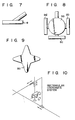
- the construction (the number of the arm members, etc.) of the movable arm supporting the probe 8 and the latitude with which this movable arm can be moved may be determined in accordance with the specification involved. Measuring a tangent plane of a concave surface is also possible by making the flat surface portion 8a of the probe small. Modifications of this invention will be described. As shown in Fig. 7, the flat portion 8a of the probe 8 need not be provided perpendicular to the axis of the probe 8.
- the probe 8 may be provided with a plurality of flat portions 9a, 9b, 9c, 9d and so on for ease of measurement.
- switch means may be provided for switching the flat portions of the probe to measure a tangent plane of the object.
- the flat portion of the probe need not be shaped into a circle, but may be shaped into a polygonal, ellipse, or star. In Fig. 9, the flat portion is shaped into a star.
- the movable arm need not be provided with rotatable joints.
- the movable arm may be designed to contract and expand, or slide.
- encoder means may be provided for measuring the arm length or the slide position to calculate tangent planes of an three-dimensional object.
- the coordinate system of the movable arm used in calculating the tangent planes may be a rectangular coordinate system as shown in Fig. 10, a cylindrical
Abstract
Description
- The present invention relates to a device for measuring shapes of three-dimensional objects.
- In, for example, a manufacturing plant, when a product such as a machine is automatically assembled, a device for automatically discriminating the shape of three-dimensional objects such as machine parts becomes necessary for selecting suitable parts among them. Conventionally, in order to discriminate the shape of three-dimensional objects, each object is regarded as a polyhedron, and the position of each vertex (the intersection of three or more adjacent planes) of the polyhedron is measured to determine each plane, to approximately determine the shape of the object on the basis of the space surrounded or defined by such planes. With this method, where the object is a polyhedron, it is possible to precisely discriminate the shape of that object. However, where the object to be measured has a curved surface, since no clear vertex is found on that surface, a measurement is made of the positions of points in the proximity of the object surface to approximately determine the shape of the object from the positions of those points. In this case, therefore, the problem arises that errors in measurement are great. In addition, the method of measuring the positions of the vertexes of the object has a drawback in that the measurement time increases.
- Japanese Laid-Open Patent Publication No.55-55210 discloses a device for measuring a three-dimensional curved surface. The device is equipped with a movable arm having a given number of arm members which are coupled in tandem by joints. The movable arm also has a probe at the forward end of the foremost arm member. In this device, the angle-of-rotation data pertaining to each joint is collected, while moving the probe on the curved surface of the object to thereby determine the three-dimensional surface thereof. However, when this device is applied to the measurement of the shape of a three-dimensional object, the times of measurements unavoidably increases.
- An object of the present invention is to provide a measuring device which can easily measure, with high precision, the shape of a three-dimensional object.
- Another object of the present invention is to provide a measuring device arranged to directly measure a tangent plane passing through a given point on the surface of a three-dimensional object, thereby to determine the shape of the object on the basis of a plurality of tangent planes.
- A measuring device of the present invention comprises a movable arm having a plurality of movable arm members coupled in tandem by joints; a probe mounted on a forward end of the movable arm by a universal joint for contacting the three-dimensional object to be measured, the probe having at its forward end a flat surface portion which contacts the three-dimensional object; angle-of-rotation encoder means for detecting the angles of rotation of the movable arm members ana the probe during the measurement; and means for computing the direction of the flat surface portion of the probe at the contact point between the object and the flat surface of the probe on the basis of information from the angle-of-rotation encoder means and information on dimensions of the movable arm members, to thereby determine a tangent plane, and determining the shape of the object from a plurality of the tangent planes at the contact points.
- This invention can be more fully understood from the following detailed description when taken in conjunction with the accompanying drawings, in which:
- Fig. 1 is a schematic perspective view of a device for measuring the shape of a three-dimensional object according to an embodiment of the present invention;
- Fig. 2 is a view which serves to explain the method of measuring the shape of a three-dimensional object by using the device shown in Fig. 1;
- Fig. 3 is a block diagram for measuring the shape of a three-dimensional object;
- Fig. 4 shows a polyhedral three-dimensional object, the shape of which is easy to measure;
- Figs. 5 and 6 are views for explaining the measuring operation performed with respect to the three-dimensional curveo surface of an object to be measured;
- Fig. 7 shows a modification of the foremost end of the probe;
- Fig. 8 shows a modification of the probe;
- Fig. 9 shows a modification of the flat portion of the probe; and
- Figs. 10 to 12 show various coordinate systems of the movable arm used for calculating tangent planes of a three-dimensional object.
- In a device for measuring the shape of a three-dimensional object according to an embodiment of the present invention, as shown in Fig. 1, a
movable arm 1 is mounted on abase 2. On thisbase 2, a three-dimensional object, the shape of which is to be measured, is placed. Themovable arm 1 comprises a supportingcolumn 3 mounted on thebase 2 in such a manner that it is rotatable in a plane parallel to the plane of thebase 2, afirst arm member 4 having its one end supported on the top of supportingcolumn 3 to be swingable in a direction perpendicular to the surface of thebase 2, a second arm member 5 having its one end supported on the other end of thefirst arm member 4 to be swingable in the same direction as thefirst arm member 4, and a third arm member 6 having its one end supported on the other end of the secono arm member 5 to be swingable in the same direction as the first anasecond arm members 4 and 5. On the forward end of the third arm member 6, aprobe 8 is mounted through aprobe supporting member 7 in such a manner that it is three-dimensionally swingable with respect to the third arm member 6. Theprobe 8 is formed, at its forward end, with a flat surface portion 8a perpendicular to the axis of theprobe 8. In other words, theprobe 8 is coupled to the third arm member 6 by way of a universal joint. Theprobe 8 is utilized in such a manner that its flat surface portion 8a contacts a three-dimensional object to determine a tangent plane of this object. - In the above-mentioned device, the x-y-z space, which is referenced to the surface of the
base 2, is defined as shown in Fig. 2. That is to say, when the three-dimensional object is measured, it is assumed that an angle of rotation, as defined with respect to the X axis, of the supportingcolumn 3 provioed in the Z-axial direction perpendicular to the plane (x-yJ, which is defined by the surface of thebase 2, is φ. Thefirst arm member 4 rotates through an angle of el with respect to the plane (x-y) about the center Xl of rotation of a joint located at the height h of the supportingcolumn 3. The second arm member 5 rotates through an angle of a2 with respect to thefirst arm member 4 about the . center X2 of rotation of a joint between thefirst arm member 4 and the second arm member 5. The third arm member 6 rotates through an angle of θ3 with respect to the second arm member 5 about the center X3 of rotation of a joint between the second arm member 5 and the thiro arm member 6. Theprobe supporting member 7 is mounted on the third arm member 6 to be swingable about a position X4. When theprobe supporting member 7 rotates with respect to the third arm member 6, theprobe 8 rotates through an angle of e4 with respect to the Z axis in the plane in which thearm members 4, 5 and 6 rotate. Further, theprobe 8 also rotates through an angle of ψ with respect to the plane in which each arm member rotates. The first, second andthird arm members 4, 5 and 6 have lengths of 11, 12 and ℓ3, respectively. The flat surface portion 8a of theprobe 8 is provided at a position X0, which is spaced by a distance of 14 from the center X4 of theprobe supporting member 7. It will be understood that theprobe 8 can be directed in any direction by way of the universal joint. Although not shown, an angle-of-rotation encoder such as a potentiometer which is intended to detect the angle of rotation is coupled to each rotating shaft of the supportingcolumn 3,arm members 4, 5 and 6, andprobe supporting member 7. - Hereafter, a description will be made of how to determine tangent planes of a three-dimensional object by using the above-mentioned device. As shown in Fig. 3, information from the angle-of-rotation encoders lla to 11f to detect the angles of rotation φ, el, e2, e3 and e4 is supplied to a
computer 12 which receives, from a register 13, the known data h, ℓ1, ℓ2, 13 and 14 of the above-mentioned movable arm and computes the center position XO of theprobe 8 contacted with the three-dimensional object and the angle of a tangent plane thereof at the contact point (XO) of the flat surface portion 8a or theprobe 8 with the object. - When it is now assumed that the coordinates of Xi are expressed in the form of (xi, yi, zi), the coordinates of Xl can be expressed as follows:


- The coordinates of X2 can be expressed as follows:


- Similarly, the respective coordinates of X3, X4 and X0 can be expressed as follows:


- Accordingly, the coordinates of the center position XO of the flat surface portion 8a of the
probe 8 can be calculated from the above as follows:


- The normal line of the tangent-plane of the object at the contact point (XO) of the
probe 8 with the object is inclined at an angle of (φ + β) with respect to the X axis in the plane (x - y) and also is upwardly inclined at an angle of a with respect to the plane (x - y). Accordingly, the tangent plane can be expressed as follows: -

- By sequentially determining the tangent planes of the object, it is possible to effectively determine the shape of the object which is enclosed by a plurality of measured tangent planes. Finally, the shape of the object is defined by a space which is expressed as follows:


- As shown in Fig. 4, where the object is a polyhedron, it is possible, as apparent from the foregoing description, to precisely determine its shape with a lesser number of measuring times. Where an object has a curved surface as shown in Fig. 5, it is possible to relatively precisely determine its shape by expressing the curved surface by a plurality of tangent planes. In this case, even when the flat surface portion 8a of the
probe 8 is moved parallel as shown in Fig. 6, the measuring error is very small because no variation occurs in the angle of the tangent plane. - As will be clear from the foregoing description, according to the shape measuring device of the present invention, it is possible to measure the shape of an object consisting of a polyhedron constituted by polygonal planes, with an appreciably lesser number of measuring times than in the case of measuring each vertex of the object. Yet, since each tangent plane is directly determined, factors causing the production of errors involved are small in number.
- The present invention is not limited to the above-mentioned embodiment. For example, the construction (the number of the arm members, etc.) of the movable arm supporting the
probe 8 and the latitude with which this movable arm can be moved, may be determined in accordance with the specification involved. Measuring a tangent plane of a concave surface is also possible by making the flat surface portion 8a of the probe small. Modifications of this invention will be described. As shown in Fig. 7, the flat portion 8a of theprobe 8 need not be provided perpendicular to the axis of theprobe 8. Since the constant angle between the flat portion 8a of theprobe 8 and the axis of theprobe 8 is known in advance, the angle may be compensated for calculating tangent planes of the three-dimensional object. As shown in Fig. 8, theprobe 8 may be provided with a plurality offlat portions 9a, 9b, 9c, 9d and so on for ease of measurement. In this case, switch means may be provided for switching the flat portions of the probe to measure a tangent plane of the object. The flat portion of the probe need not be shaped into a circle, but may be shaped into a polygonal, ellipse, or star. In Fig. 9, the flat portion is shaped into a star. The movable arm need not be provided with rotatable joints. The movable arm may be designed to contract and expand, or slide. In this case, encoder means may be provided for measuring the arm length or the slide position to calculate tangent planes of an three-dimensional object. The coordinate system of the movable arm used in calculating the tangent planes may be a rectangular coordinate system as shown in Fig. 10, a cylindrical - coordinate system as shown in Fig . 11, or a polar coordinate system as shown in Fig. 12.
Claims (8)
Applications Claiming Priority (2)
| Application Number | Priority Date | Filing Date | Title |
|---|---|---|---|
| JP59027424A JPS60170709A (en) | 1984-02-16 | 1984-02-16 | Measuring insturment for shape |
| JP27424/84 | 1984-02-16 |
Publications (2)
| Publication Number | Publication Date |
|---|---|
| EP0155084A1 true EP0155084A1 (en) | 1985-09-18 |
| EP0155084B1 EP0155084B1 (en) | 1988-07-06 |
Family
ID=12220721
Family Applications (1)
| Application Number | Title | Priority Date | Filing Date |
|---|---|---|---|
| EP85300949A Expired EP0155084B1 (en) | 1984-02-16 | 1985-02-13 | Device for measuring the shape of a three-dimensional object |
Country Status (4)
| Country | Link |
|---|---|
| US (1) | US4703443A (en) |
| EP (1) | EP0155084B1 (en) |
| JP (1) | JPS60170709A (en) |
| DE (1) | DE3563652D1 (en) |
Cited By (20)
| Publication number | Priority date | Publication date | Assignee | Title |
|---|---|---|---|---|
| WO1988004404A1 (en) * | 1986-12-10 | 1988-06-16 | Gregory James Mcdonald | Coordinate measuring system |
| EP0295217A1 (en) * | 1987-05-05 | 1988-12-14 | GARDA IMPIANTI S.r.l. | Apparatus to measure and/or check the position and orientation of characteristic spots or areas in structures, particularly in motor-vehicle bodies |
| FR2634279A1 (en) * | 1988-07-13 | 1990-01-19 | France Etat Armement | Device for three-dimensional measurement (tracing) |
| FR2643708A1 (en) * | 1989-02-25 | 1990-08-31 | Kugelfischer G Schaefer & Co | PROBE OF MEASURE FOLLOWING SEVERAL COORDINATES |
| NL8900866A (en) * | 1989-04-07 | 1990-11-01 | Kegro Deuren B V | Measuring device determining shape of door frame - uses hinged arms and sensors to detect spatial positions of points around frame |
| FR2653761A1 (en) * | 1989-10-27 | 1991-05-03 | Potain Sa | HIGH-DIMENSION AND HIGH-CAPACITY HANDLING ROBOT FOR OPEN-USE USE. |
| EP0305473A4 (en) * | 1987-02-26 | 1992-04-15 | Klaus Ulbrich | Probe, motion guiding device, position sensing apparatus, and position sensing method |
| WO1992014120A1 (en) * | 1991-01-30 | 1992-08-20 | Groenskov Leif | Apparatus for the scanning of a profile and use hereof |
| EP0522610A1 (en) * | 1991-06-26 | 1993-01-13 | Sulzer - Escher Wyss AG | Method and apparatus for surface-contour determination of rotor blades in hydraulic machines |
| EP0541811A1 (en) * | 1991-05-28 | 1993-05-19 | Kabushiki Kaisha Toshiba | Working device |
| EP0672885A2 (en) * | 1994-03-18 | 1995-09-20 | C.E. Johansson Ab | A coordinate measuring machine |
| EP0729005A1 (en) * | 1995-02-23 | 1996-08-28 | Institut Für Fertigungstechnik Der Tu Graz | Measuring device with 6 degrees of freedom |
| EP0730210A1 (en) * | 1995-03-03 | 1996-09-04 | Faro Technologies Inc. | Three dimensional coordinate measuring apparatus |
| GB2305253A (en) * | 1995-09-12 | 1997-04-02 | British United Shoe Machinery | Outline aid for a line digitiser |
| FR2772121A1 (en) * | 1997-12-10 | 1999-06-11 | Metalscan | Automatic determination of the position of a movable sensor array |
| USD491965S1 (en) | 2002-02-14 | 2004-06-22 | Faro Technologies, Inc. | Portable coordinate measurement machine |
| US6892465B2 (en) | 2002-02-14 | 2005-05-17 | Faro Technologies, Inc. | Portable coordinate measurement machine with integrated magnetic mount |
| USRE42055E1 (en) | 2002-02-14 | 2011-01-25 | Faro Technologies, Inc. | Method for improving measurement accuracy of a portable coordinate measurement machine |
| USRE42082E1 (en) | 2002-02-14 | 2011-02-01 | Faro Technologies, Inc. | Method and apparatus for improving measurement accuracy of a portable coordinate measurement machine |
| US7881896B2 (en) | 2002-02-14 | 2011-02-01 | Faro Technologies, Inc. | Portable coordinate measurement machine with integrated line laser scanner |
Families Citing this family (91)
| Publication number | Priority date | Publication date | Assignee | Title |
|---|---|---|---|---|
| DE3679622D1 (en) * | 1985-08-01 | 1991-07-11 | Brown & Sharpe Mfg | METHOD AND DEVICE FOR THREE-DIMENSIONAL MEASUREMENT OF AN OBJECT. |
| US4945501A (en) * | 1987-01-20 | 1990-07-31 | The Warner & Swasey Company | Method for determining position within the measuring volume of a coordinate measuring machine and the like and system therefor |
| IT1211390B (en) * | 1987-10-06 | 1989-10-18 | Dea Spa | INTERACTIVE GRAPHIC SYSTEM FOR THE MATHEMATIZATION OF PHYSICAL MODELS |
| US5212646A (en) * | 1987-12-19 | 1993-05-18 | Renishaw Plc | Method of using a mounting for surface-sensing stylus |
| GB8729638D0 (en) * | 1987-12-19 | 1988-02-03 | Renishaw Plc | Mounting for surface sensing device |
| US5152072A (en) * | 1988-02-18 | 1992-10-06 | Renishaw Plc | Surface-sensing device |
| GB8803847D0 (en) * | 1988-02-18 | 1988-03-16 | Renishaw Plc | Mounting for surface-sensing device |
| US5189806A (en) * | 1988-12-19 | 1993-03-02 | Renishaw Plc | Method of and apparatus for scanning the surface of a workpiece |
| JP2694669B2 (en) * | 1989-06-09 | 1997-12-24 | 株式会社日立製作所 | Robot motion control method |
| US5198990A (en) * | 1990-04-23 | 1993-03-30 | Fanamation, Inc. | Coordinate measurement and inspection methods and apparatus |
| US5245555A (en) * | 1990-10-15 | 1993-09-14 | Vilches Jose I | System for measuring vector coordinates |
| DE4238139C2 (en) * | 1992-11-12 | 2002-10-24 | Zeiss Carl | The coordinate |
| US5402582A (en) * | 1993-02-23 | 1995-04-04 | Faro Technologies Inc. | Three dimensional coordinate measuring apparatus |
| US6535794B1 (en) | 1993-02-23 | 2003-03-18 | Faro Technologoies Inc. | Method of generating an error map for calibration of a robot or multi-axis machining center |
| US5721566A (en) | 1995-01-18 | 1998-02-24 | Immersion Human Interface Corp. | Method and apparatus for providing damping force feedback |
| US6437771B1 (en) | 1995-01-18 | 2002-08-20 | Immersion Corporation | Force feedback device including flexure member between actuator and user object |
| WO1995002801A1 (en) * | 1993-07-16 | 1995-01-26 | Immersion Human Interface | Three-dimensional mechanical mouse |
| US5739811A (en) | 1993-07-16 | 1998-04-14 | Immersion Human Interface Corporation | Method and apparatus for controlling human-computer interface systems providing force feedback |
| US5767839A (en) * | 1995-01-18 | 1998-06-16 | Immersion Human Interface Corporation | Method and apparatus for providing passive force feedback to human-computer interface systems |
| US5805140A (en) | 1993-07-16 | 1998-09-08 | Immersion Corporation | High bandwidth force feedback interface using voice coils and flexures |
| US5734373A (en) * | 1993-07-16 | 1998-03-31 | Immersion Human Interface Corporation | Method and apparatus for controlling force feedback interface systems utilizing a host computer |
| US5724264A (en) * | 1993-07-16 | 1998-03-03 | Immersion Human Interface Corp. | Method and apparatus for tracking the position and orientation of a stylus and for digitizing a 3-D object |
| US5731804A (en) * | 1995-01-18 | 1998-03-24 | Immersion Human Interface Corp. | Method and apparatus for providing high bandwidth, low noise mechanical I/O for computer systems |
| US5625576A (en) * | 1993-10-01 | 1997-04-29 | Massachusetts Institute Of Technology | Force reflecting haptic interface |
| US5623582A (en) * | 1994-07-14 | 1997-04-22 | Immersion Human Interface Corporation | Computer interface or control input device for laparoscopic surgical instrument and other elongated mechanical objects |
| US5821920A (en) * | 1994-07-14 | 1998-10-13 | Immersion Human Interface Corporation | Control input device for interfacing an elongated flexible object with a computer system |
| US5510977A (en) * | 1994-08-02 | 1996-04-23 | Faro Technologies Inc. | Method and apparatus for measuring features of a part or item |
| US6850222B1 (en) | 1995-01-18 | 2005-02-01 | Immersion Corporation | Passive force feedback for computer interface devices |
| DE19681395T1 (en) * | 1995-05-16 | 1998-04-16 | Brown & Sharpe Mfg | Coordinate measuring machine with articulated arm |
| US5691898A (en) * | 1995-09-27 | 1997-11-25 | Immersion Human Interface Corp. | Safe and low cost computer peripherals with force feedback for consumer applications |
| US7113166B1 (en) | 1995-06-09 | 2006-09-26 | Immersion Corporation | Force feedback devices using fluid braking |
| US6697748B1 (en) | 1995-08-07 | 2004-02-24 | Immersion Corporation | Digitizing system and rotary table for determining 3-D geometry of an object |
| US5959613A (en) | 1995-12-01 | 1999-09-28 | Immersion Corporation | Method and apparatus for shaping force signals for a force feedback device |
| JPH0997112A (en) * | 1995-09-28 | 1997-04-08 | Toyota Motor Corp | Locus control method and device therefor |
| USD377932S (en) * | 1995-10-31 | 1997-02-11 | Immersion Human Interface Corporation | Mechanical digitizing arm used to input three dimensional data into a computer |
| US6704001B1 (en) | 1995-11-17 | 2004-03-09 | Immersion Corporation | Force feedback device including actuator with moving magnet |
| US6147674A (en) | 1995-12-01 | 2000-11-14 | Immersion Corporation | Method and apparatus for designing force sensations in force feedback computer applications |
| US8508469B1 (en) | 1995-12-01 | 2013-08-13 | Immersion Corporation | Networked applications including haptic feedback |
| US6219032B1 (en) | 1995-12-01 | 2001-04-17 | Immersion Corporation | Method for providing force feedback to a user of an interface device based on interactions of a controlled cursor with graphical elements in a graphical user interface |
| US7027032B2 (en) | 1995-12-01 | 2006-04-11 | Immersion Corporation | Designing force sensations for force feedback computer applications |
| US6028593A (en) | 1995-12-01 | 2000-02-22 | Immersion Corporation | Method and apparatus for providing simulated physical interactions within computer generated environments |
| US6859819B1 (en) | 1995-12-13 | 2005-02-22 | Immersion Corporation | Force feedback enabled over a computer network |
| US6078308A (en) | 1995-12-13 | 2000-06-20 | Immersion Corporation | Graphical click surfaces for force feedback applications to provide user selection using cursor interaction with a trigger position within a boundary of a graphical object |
| US5675514A (en) * | 1996-04-10 | 1997-10-07 | Lefebvre; Guy | Telemetric spacial data recorder |
| US5829148A (en) * | 1996-04-23 | 1998-11-03 | Eaton; Homer L. | Spatial measuring device |
| US5758429A (en) * | 1996-05-14 | 1998-06-02 | Farzan; Farshad | Translation and rotation coupled positioning method and apparatus |
| US6084587A (en) | 1996-08-02 | 2000-07-04 | Sensable Technologies, Inc. | Method and apparatus for generating and interfacing with a haptic virtual reality environment |
| US6024576A (en) * | 1996-09-06 | 2000-02-15 | Immersion Corporation | Hemispherical, high bandwidth mechanical interface for computer systems |
| DE69735353T2 (en) * | 1996-10-23 | 2006-11-30 | Anjou Lasercad Inc. | TELEMETRICAL RAIL DATA RECEPTION DEVICE |
| US5828197A (en) | 1996-10-25 | 1998-10-27 | Immersion Human Interface Corporation | Mechanical interface having multiple grounded actuators |
| US6191796B1 (en) | 1998-01-21 | 2001-02-20 | Sensable Technologies, Inc. | Method and apparatus for generating and interfacing with rigid and deformable surfaces in a haptic virtual reality environment |
| US6421048B1 (en) | 1998-07-17 | 2002-07-16 | Sensable Technologies, Inc. | Systems and methods for interacting with virtual objects in a haptic virtual reality environment |
| US6985133B1 (en) | 1998-07-17 | 2006-01-10 | Sensable Technologies, Inc. | Force reflecting haptic interface |
| US6552722B1 (en) | 1998-07-17 | 2003-04-22 | Sensable Technologies, Inc. | Systems and methods for sculpting virtual objects in a haptic virtual reality environment |
| US6195618B1 (en) | 1998-10-15 | 2001-02-27 | Microscribe, Llc | Component position verification using a probe apparatus |
| FR2786651B1 (en) | 1998-11-27 | 2002-10-25 | Commissariat Energie Atomique | ULTRASONIC CONTACT TRANSDUCER, WITH MULTIPLE ELEMENTS |
| ES2185431B1 (en) * | 1999-02-19 | 2004-10-16 | Universidad De Valladolid | PORTABLE MODULAR STRUCTURE MACHINE TO MEASURE THE DIMENSIONS OF THE OBJECTS AND CONTROL THE MANUFACTURING PROCESS FOR THE GENERATION OF SURFACES. |
| JP3443030B2 (en) * | 1999-03-31 | 2003-09-02 | オークマ株式会社 | measuring device |
| NL1013479C1 (en) * | 1999-11-03 | 2001-05-09 | Theodorus Wilhelmus Antonius C | Measuring device comprising a movable measuring probe. |
| KR100371867B1 (en) * | 1999-12-09 | 2003-02-11 | 사단법인 고등기술연구원 연구조합 | Apparatus for measuring three dimensional position |
| US6668466B1 (en) * | 2000-10-19 | 2003-12-30 | Sandia Corporation | Highly accurate articulated coordinate measuring machine |
| US6519860B1 (en) * | 2000-10-19 | 2003-02-18 | Sandia Corporation | Position feedback control system |
| US6867770B2 (en) | 2000-12-14 | 2005-03-15 | Sensable Technologies, Inc. | Systems and methods for voxel warping |
| US6958752B2 (en) | 2001-01-08 | 2005-10-25 | Sensable Technologies, Inc. | Systems and methods for three-dimensional modeling |
| US6973734B2 (en) * | 2002-02-14 | 2005-12-13 | Faro Technologies, Inc. | Method for providing sensory feedback to the operator of a portable measurement machine |
| US7073271B2 (en) * | 2002-02-14 | 2006-07-11 | Faro Technologies Inc. | Portable coordinate measurement machine |
| US7246030B2 (en) | 2002-02-14 | 2007-07-17 | Faro Technologies, Inc. | Portable coordinate measurement machine with integrated line laser scanner |
| US7519493B2 (en) | 2002-02-14 | 2009-04-14 | Faro Technologies, Inc. | Portable coordinate measurement machine with integrated line laser scanner |
| US6952882B2 (en) * | 2002-02-14 | 2005-10-11 | Faro Technologies, Inc. | Portable coordinate measurement machine |
| US6671651B2 (en) | 2002-04-26 | 2003-12-30 | Sensable Technologies, Inc. | 3-D selection and manipulation with a multiple dimension haptic interface |
| KR100471273B1 (en) * | 2002-11-08 | 2005-03-08 | 현대자동차주식회사 | Portable 3 dimension coordinate system |
| DE20218352U1 (en) * | 2002-11-26 | 2003-01-23 | Reishauer Ag | Centering device for aligning pre-toothed workpieces on gear finishing machines |
| US7010457B2 (en) | 2002-12-23 | 2006-03-07 | Kenneth Wargon | Apparatus and method for producing a numeric display corresponding to the volume of a selected segment of an item |
| US7382378B2 (en) | 2003-10-30 | 2008-06-03 | Sensable Technologies, Inc. | Apparatus and methods for stenciling an image |
| US7095418B2 (en) | 2003-10-30 | 2006-08-22 | Sensable Technologies, Inc. | Apparatus and methods for texture mapping |
| US7411576B2 (en) | 2003-10-30 | 2008-08-12 | Sensable Technologies, Inc. | Force reflecting haptic interface |
| US7889209B2 (en) | 2003-12-10 | 2011-02-15 | Sensable Technologies, Inc. | Apparatus and methods for wrapping texture onto the surface of a virtual object |
| US7626589B2 (en) | 2003-12-10 | 2009-12-01 | Sensable Technologies, Inc. | Haptic graphical user interface for adjusting mapped texture |
| US7149596B2 (en) | 2004-01-13 | 2006-12-12 | Sensable Technologies, Inc. | Apparatus and methods for modifying a model of an object to enforce compliance with a manufacturing constraint |
| US7152456B2 (en) * | 2004-01-14 | 2006-12-26 | Romer Incorporated | Automated robotic measuring system |
| US7693325B2 (en) | 2004-01-14 | 2010-04-06 | Hexagon Metrology, Inc. | Transprojection of geometry data |
| WO2007033273A2 (en) * | 2005-09-13 | 2007-03-22 | Romer Incorporated | Vehicle comprising an articulator of a coordinate measuring machine |
| US20070209224A1 (en) * | 2005-09-21 | 2007-09-13 | James Bush | Method and apparatus for determining the normal distance between a plane and a point |
| BRPI0505860A (en) * | 2005-12-09 | 2007-09-25 | Ubea | dental structure digitizer, method for reading three-dimensional data from a dental structure and mouth scanner kit |
| WO2008109090A1 (en) * | 2007-03-06 | 2008-09-12 | Kenneth Wargon | Apparatus and method for determining and numerically displaying a volume |
| US7587834B2 (en) * | 2008-02-07 | 2009-09-15 | Eaton Homer L | Motorized coordinate measuring device |
| US7665223B2 (en) * | 2008-06-20 | 2010-02-23 | Delta Ii, I.P., Trust | Measuring device with extensible cord and method |
| FR2943130A1 (en) * | 2009-03-13 | 2010-09-17 | Bouygues Travaux Publics | Device for determining position and orientation of secondary body i.e. front body, relative to main body i.e. rear body, of dual-body or multiple-body mole, has slide arranged between joints and instrumented by elongation sensor |
| US9802364B2 (en) | 2011-10-18 | 2017-10-31 | 3D Systems, Inc. | Systems and methods for construction of an instruction set for three-dimensional printing of a user-customizableimage of a three-dimensional structure |
| DE102011056219A1 (en) * | 2011-12-09 | 2013-06-13 | Tyromotion Gmbh | Position sensor, sensor assembly and rehabilitation device |
| CN108839019B (en) * | 2018-06-25 | 2020-09-01 | 广州视源电子科技股份有限公司 | Method and device for determining motion path of mechanical arm |
Citations (3)
| Publication number | Priority date | Publication date | Assignee | Title |
|---|---|---|---|---|
| DE2515944A1 (en) * | 1974-04-18 | 1975-10-30 | Eaton Leonard Corp | METHOD AND DEVICE FOR MEASURING DIRECTION |
| WO1981001334A1 (en) * | 1979-11-05 | 1981-05-14 | Viln N Telskogo I Metall | Piezoelectric resonance contact pick-up |
| DE3210711A1 (en) * | 1982-03-24 | 1984-02-02 | Dr.-Ing. Höfler Meßgerätebau GmbH, 7505 Ettlingen | MULTI-COORDINATE BUTTON WITH CONTROLLED PROBE |
Family Cites Families (16)
| Publication number | Priority date | Publication date | Assignee | Title |
|---|---|---|---|---|
| SU602767A1 (en) * | 1972-11-09 | 1978-04-15 | Каунасский Политехнический Институт | Device for measuring curvature radii of thin-walled anisotropic envelopes |
| US3940854A (en) * | 1974-03-27 | 1976-03-02 | Westinghouse Electric Corporation | Three axis precision measuring device |
| IT1047307B (en) * | 1974-09-24 | 1980-09-10 | Rank Organisation Ltd | SURFACE MEASUREMENT INSTRUMENT |
| JPS5555210A (en) * | 1978-10-20 | 1980-04-23 | Hitachi Ltd | Method and apparatus for measuring three-dimentional curvature |
| US4240205A (en) * | 1979-08-20 | 1980-12-23 | The Bendix Corporation | Coordinate measuring machine |
| JPS5717015A (en) * | 1980-07-04 | 1982-01-28 | Hitachi Ltd | Robot control method |
| DE3033202C2 (en) * | 1980-09-03 | 1984-04-19 | Siemens AG, 1000 Berlin und 8000 München | Tool path interpolation method |
| JPS57132015A (en) * | 1981-02-09 | 1982-08-16 | Kosaka Kenkyusho:Kk | Coordinate transformation device |
| JPS5814006A (en) * | 1981-07-17 | 1983-01-26 | Mitsubishi Heavy Ind Ltd | Apparatus for measuring position of assembled piping |
| JPS5822411A (en) * | 1981-08-04 | 1983-02-09 | Fanuc Ltd | Industrial robot control system |
| IL63856A (en) * | 1981-09-16 | 1984-12-31 | Beta Eng & Dev Ltd | Three dimensional digitizer for digitizing the surface contour of a solid body |
| JPS5850414A (en) * | 1981-09-21 | 1983-03-24 | Japax Inc | Method for preparing position data of tool such as ball end mill |
| US4467436A (en) * | 1981-10-26 | 1984-08-21 | United States Robots, Inc. | Robot arm controller with common bus memory |
| JPS58137005A (en) * | 1982-02-08 | 1983-08-15 | Hitachi Ltd | Instantaneous processing and simultaneous multi-axis controller |
| US4477973A (en) * | 1982-07-14 | 1984-10-23 | Micro Control Systems, Inc. | Three dimensional graphics tablet |
| US4558420A (en) * | 1982-10-25 | 1985-12-10 | Gerber Scientific Inc. | Computer generated mold for contoured garment piece formation |
-
1984
- 1984-02-16 JP JP59027424A patent/JPS60170709A/en active Pending
-
1985
- 1985-02-07 US US06/699,133 patent/US4703443A/en not_active Expired - Fee Related
- 1985-02-13 DE DE8585300949T patent/DE3563652D1/en not_active Expired
- 1985-02-13 EP EP85300949A patent/EP0155084B1/en not_active Expired
Patent Citations (3)
| Publication number | Priority date | Publication date | Assignee | Title |
|---|---|---|---|---|
| DE2515944A1 (en) * | 1974-04-18 | 1975-10-30 | Eaton Leonard Corp | METHOD AND DEVICE FOR MEASURING DIRECTION |
| WO1981001334A1 (en) * | 1979-11-05 | 1981-05-14 | Viln N Telskogo I Metall | Piezoelectric resonance contact pick-up |
| DE3210711A1 (en) * | 1982-03-24 | 1984-02-02 | Dr.-Ing. Höfler Meßgerätebau GmbH, 7505 Ettlingen | MULTI-COORDINATE BUTTON WITH CONTROLLED PROBE |
Non-Patent Citations (4)
| Title |
|---|
| MICROTECNIC, no. 3, October 1982, Zürich, CH; M. SUZUKI "The New Hob Tester Model PCD-50HB", pages 57-61 * |
| PATENT ABSTRACTS OF JAPAN, vol. 6, no. 79, 18th May 1982, page ( P-115) (957); & JP-A-57-017015 (HITACHI SEISAKUSHO K.K.) 28-01-1982 * |
| PATENT ABSTRACTS OF JAPAN, vol. 7, no. 253, 10th November 1983, page (P-235) (1398); & JP-A-58-137005 (HITACHI SEISAKUSHO K.K.) 15-08-1983 * |
| SOVIET INVENTIONS ILLUSTRATED, Derwent Publication Ltd.; Week B 10, 23rd April 1979 Section Electrical, abstract no. C1200B/10, RII & SU-A-602 767 (KAUN POLY) 21-03-1978 * |
Cited By (42)
| Publication number | Priority date | Publication date | Assignee | Title |
|---|---|---|---|---|
| WO1988004404A1 (en) * | 1986-12-10 | 1988-06-16 | Gregory James Mcdonald | Coordinate measuring system |
| EP0305473A4 (en) * | 1987-02-26 | 1992-04-15 | Klaus Ulbrich | Probe, motion guiding device, position sensing apparatus, and position sensing method |
| EP0295217A1 (en) * | 1987-05-05 | 1988-12-14 | GARDA IMPIANTI S.r.l. | Apparatus to measure and/or check the position and orientation of characteristic spots or areas in structures, particularly in motor-vehicle bodies |
| FR2634279A1 (en) * | 1988-07-13 | 1990-01-19 | France Etat Armement | Device for three-dimensional measurement (tracing) |
| FR2643708A1 (en) * | 1989-02-25 | 1990-08-31 | Kugelfischer G Schaefer & Co | PROBE OF MEASURE FOLLOWING SEVERAL COORDINATES |
| NL8900866A (en) * | 1989-04-07 | 1990-11-01 | Kegro Deuren B V | Measuring device determining shape of door frame - uses hinged arms and sensors to detect spatial positions of points around frame |
| FR2653761A1 (en) * | 1989-10-27 | 1991-05-03 | Potain Sa | HIGH-DIMENSION AND HIGH-CAPACITY HANDLING ROBOT FOR OPEN-USE USE. |
| EP0428453A1 (en) * | 1989-10-27 | 1991-05-22 | Potain | Robotic manipulator of large dimensions and capacity to be used in an open environment |
| WO1992014120A1 (en) * | 1991-01-30 | 1992-08-20 | Groenskov Leif | Apparatus for the scanning of a profile and use hereof |
| US5351411A (en) * | 1991-01-30 | 1994-10-04 | Leif Gronskov | Apparatus for the scanning of a profile and use hereof |
| EP0541811A1 (en) * | 1991-05-28 | 1993-05-19 | Kabushiki Kaisha Toshiba | Working device |
| EP0541811A4 (en) * | 1991-05-28 | 1994-06-29 | Toshiba Kk | Working device |
| US5525027A (en) * | 1991-05-28 | 1996-06-11 | Kabushiki Kaisha Toshiba | Working robot |
| EP0522610A1 (en) * | 1991-06-26 | 1993-01-13 | Sulzer - Escher Wyss AG | Method and apparatus for surface-contour determination of rotor blades in hydraulic machines |
| US5611147A (en) * | 1993-02-23 | 1997-03-18 | Faro Technologies, Inc. | Three dimensional coordinate measuring apparatus |
| EP0672885A2 (en) * | 1994-03-18 | 1995-09-20 | C.E. Johansson Ab | A coordinate measuring machine |
| EP0672885A3 (en) * | 1994-03-18 | 1997-04-09 | Johansson Ab C E | A coordinate measuring machine. |
| US5767380A (en) * | 1995-02-23 | 1998-06-16 | Insitut Fur Fertigungstechnik, Technische Universitat Graz | Measuring arrangement and method for checking the geometric and dynamic accuracy of two machine elements displaceable with respect to one another |
| EP0729005A1 (en) * | 1995-02-23 | 1996-08-28 | Institut Für Fertigungstechnik Der Tu Graz | Measuring device with 6 degrees of freedom |
| EP0730210A1 (en) * | 1995-03-03 | 1996-09-04 | Faro Technologies Inc. | Three dimensional coordinate measuring apparatus |
| EP1189124A1 (en) * | 1995-03-03 | 2002-03-20 | Faro Technologies Inc. | Three dimensional coordinate measuring apparatus |
| EP1189125A1 (en) * | 1995-03-03 | 2002-03-20 | Faro Technologies Inc. | Three dimensional coordinate measuring apparatus |
| GB2305253A (en) * | 1995-09-12 | 1997-04-02 | British United Shoe Machinery | Outline aid for a line digitiser |
| FR2772121A1 (en) * | 1997-12-10 | 1999-06-11 | Metalscan | Automatic determination of the position of a movable sensor array |
| EP0926463A1 (en) * | 1997-12-10 | 1999-06-30 | Metalscan | Apparatus for determining the position of an assembly of measuring probes |
| US6935036B2 (en) | 2002-02-14 | 2005-08-30 | Faro Technologies, Inc. | Portable coordinate measurement machine |
| US7881896B2 (en) | 2002-02-14 | 2011-02-01 | Faro Technologies, Inc. | Portable coordinate measurement machine with integrated line laser scanner |
| US6904691B2 (en) | 2002-02-14 | 2005-06-14 | Faro Technologies, Inc. | Portable coordinate measurement machine with improved counter balance |
| US6920697B2 (en) | 2002-02-14 | 2005-07-26 | Faro Technologies, Inc. | Portable coordinate measurement machine with integrated touch probe and improved handle assembly |
| US6925722B2 (en) | 2002-02-14 | 2005-08-09 | Faro Technologies, Inc. | Portable coordinate measurement machine with improved surface features |
| USD491965S1 (en) | 2002-02-14 | 2004-06-22 | Faro Technologies, Inc. | Portable coordinate measurement machine |
| US7043847B2 (en) | 2002-02-14 | 2006-05-16 | Faro Technologies, Inc. | Portable coordinate measurement machine having on-board power supply |
| USRE42055E1 (en) | 2002-02-14 | 2011-01-25 | Faro Technologies, Inc. | Method for improving measurement accuracy of a portable coordinate measurement machine |
| USRE42082E1 (en) | 2002-02-14 | 2011-02-01 | Faro Technologies, Inc. | Method and apparatus for improving measurement accuracy of a portable coordinate measurement machine |
| US6892465B2 (en) | 2002-02-14 | 2005-05-17 | Faro Technologies, Inc. | Portable coordinate measurement machine with integrated magnetic mount |
| US8572858B2 (en) | 2002-02-14 | 2013-11-05 | Faro Technologies, Inc. | Portable coordinate measurement machine having a removable external sensor |
| US8595948B2 (en) | 2002-02-14 | 2013-12-03 | Faro Technologies, Inc. | Portable coordinate measurement machine with a rotatable handle |
| US8607467B2 (en) | 2002-02-14 | 2013-12-17 | Faro Technologies, Inc. | Portable coordinate measurement machine |
| US8931182B2 (en) | 2002-02-14 | 2015-01-13 | Faro Technologies, Inc. | Portable coordinate measurement machine having a handle that includes electronics |
| US9410787B2 (en) | 2002-02-14 | 2016-08-09 | Faro Technologies, Inc. | Portable coordinate measurement machine having a bearing assembly with an optical encoder |
| US9513100B2 (en) | 2002-02-14 | 2016-12-06 | Faro Technologies, Inc. | Portable coordinate measurement machine having a handle that includes electronics |
| US10168134B2 (en) | 2002-02-14 | 2019-01-01 | Faro Technologies, Inc. | Portable coordinate measurement machine having a handle that includes electronics |
Also Published As
| Publication number | Publication date |
|---|---|
| EP0155084B1 (en) | 1988-07-06 |
| US4703443A (en) | 1987-10-27 |
| JPS60170709A (en) | 1985-09-04 |
| DE3563652D1 (en) | 1988-08-11 |
Similar Documents
| Publication | Publication Date | Title |
|---|---|---|
| EP0155084A1 (en) | Device for measuring the shape of a three-dimensional object | |
| US4859817A (en) | Feeler for omnidirectional contactor system | |
| EP1390688B1 (en) | Apparatus and method for automatically determining the position of a measuring arm on the basis of an array of reference points | |
| US4972090A (en) | Method and apparatus for measuring and inspecting articles of manufacture for configuration | |
| US5065145A (en) | Method and apparatus for producing signals corresponding to the position of a cursor | |
| EP0395811B1 (en) | Optical probe | |
| CA1065919A (en) | Assymmetric six-degree-of-freedom force-transducer system for a computer-controlled manipulator system | |
| US5822877A (en) | Multi-probe system for dimensional metrology | |
| US3944798A (en) | Method and apparatus for measuring direction | |
| EP0329635A2 (en) | Method for determining positional errors and for compensating for such errors, and apparatus for carrying out the method | |
| US4928392A (en) | Diameter gauge | |
| US4521966A (en) | Method and apparatus for determining the position of the center of a circular object | |
| EP0497813B1 (en) | Calibration of measuring apparatus | |
| SE443232B (en) | SET AND DEVICE FOR RIGHT-RESPECTIVE PLANET Saturation | |
| GB1582073A (en) | Position measuring instrument | |
| US4355467A (en) | Method and apparatus for checking parts of a constant velocity joint | |
| KR910001268B1 (en) | Checking machine | |
| US6737632B2 (en) | Control device with mobile component mounted on a ball pivot | |
| JPH01306152A (en) | Measuring device for cutting tool | |
| JPS58155301A (en) | Configuration measuring device by using three dimensional coordinate measuring machine | |
| RU2011153C1 (en) | Method of calibrating measuring head | |
| JP2572936B2 (en) | Shape measuring instruments | |
| JPS63175716A (en) | Measuring instrument for tooth profile error | |
| JPH07243822A (en) | Method and device for measuring three-dimensional shape | |
| KR100270966B1 (en) | Orientation measuring system of industrial robot |
Legal Events
| Date | Code | Title | Description |
|---|---|---|---|
| PUAI | Public reference made under article 153(3) epc to a published international application that has entered the european phase |
Free format text: ORIGINAL CODE: 0009012 |
|
| 17P | Request for examination filed |
Effective date: 19850222 |
|
| AK | Designated contracting states |
Designated state(s): DE FR GB |
|
| 17Q | First examination report despatched |
Effective date: 19870220 |
|
| GRAA | (expected) grant |
Free format text: ORIGINAL CODE: 0009210 |
|
| AK | Designated contracting states |
Kind code of ref document: B1 Designated state(s): DE GB |
|
| REF | Corresponds to: |
Ref document number: 3563652 Country of ref document: DE Date of ref document: 19880811 |
|
| PLBE | No opposition filed within time limit |
Free format text: ORIGINAL CODE: 0009261 |
|
| STAA | Information on the status of an ep patent application or granted ep patent |
Free format text: STATUS: NO OPPOSITION FILED WITHIN TIME LIMIT |
|
| 26N | No opposition filed | ||
| PGFP | Annual fee paid to national office [announced via postgrant information from national office to epo] |
Ref country code: GB Payment date: 19970204 Year of fee payment: 13 |
|
| PGFP | Annual fee paid to national office [announced via postgrant information from national office to epo] |
Ref country code: DE Payment date: 19970221 Year of fee payment: 13 |
|
| PG25 | Lapsed in a contracting state [announced via postgrant information from national office to epo] |
Ref country code: GB Free format text: LAPSE BECAUSE OF NON-PAYMENT OF DUE FEES Effective date: 19980213 |
|
| GBPC | Gb: european patent ceased through non-payment of renewal fee |
Effective date: 19980213 |
|
| PG25 | Lapsed in a contracting state [announced via postgrant information from national office to epo] |
Ref country code: DE Free format text: LAPSE BECAUSE OF NON-PAYMENT OF DUE FEES Effective date: 19981103 |