EP0154404B1 - Processing system for aligning two picture images - Google Patents
Processing system for aligning two picture images Download PDFInfo
- Publication number
- EP0154404B1 EP0154404B1 EP85300648A EP85300648A EP0154404B1 EP 0154404 B1 EP0154404 B1 EP 0154404B1 EP 85300648 A EP85300648 A EP 85300648A EP 85300648 A EP85300648 A EP 85300648A EP 0154404 B1 EP0154404 B1 EP 0154404B1
- Authority
- EP
- European Patent Office
- Prior art keywords
- image
- data
- image segment
- misalignment
- pair
- Prior art date
- Legal status (The legal status is an assumption and is not a legal conclusion. Google has not performed a legal analysis and makes no representation as to the accuracy of the status listed.)
- Expired
Links
- 238000012545 processing Methods 0.000 title claims description 6
- 230000015654 memory Effects 0.000 claims description 56
- 238000001514 detection method Methods 0.000 claims description 52
- 239000013598 vector Substances 0.000 claims description 37
- 238000011156 evaluation Methods 0.000 claims description 29
- 238000000034 method Methods 0.000 claims description 25
- 230000006870 function Effects 0.000 claims description 15
- 239000011159 matrix material Substances 0.000 claims description 5
- 230000007423 decrease Effects 0.000 claims description 4
- 238000003672 processing method Methods 0.000 claims 1
- 238000006073 displacement reaction Methods 0.000 description 11
- 230000008569 process Effects 0.000 description 11
- 230000008859 change Effects 0.000 description 5
- 230000005540 biological transmission Effects 0.000 description 4
- 230000015572 biosynthetic process Effects 0.000 description 4
- 238000010586 diagram Methods 0.000 description 4
- 238000003786 synthesis reaction Methods 0.000 description 4
- 239000000284 extract Substances 0.000 description 3
- 230000004044 response Effects 0.000 description 3
- 230000007704 transition Effects 0.000 description 3
- 230000000007 visual effect Effects 0.000 description 3
- 230000002411 adverse Effects 0.000 description 2
- 238000006243 chemical reaction Methods 0.000 description 2
- 238000002591 computed tomography Methods 0.000 description 2
- 238000012937 correction Methods 0.000 description 2
- 230000000694 effects Effects 0.000 description 2
- 230000002123 temporal effect Effects 0.000 description 2
- 210000000988 bone and bone Anatomy 0.000 description 1
- 238000002059 diagnostic imaging Methods 0.000 description 1
- 238000003384 imaging method Methods 0.000 description 1
- 238000012986 modification Methods 0.000 description 1
- 230000004048 modification Effects 0.000 description 1
- 210000000056 organ Anatomy 0.000 description 1
- 230000008520 organization Effects 0.000 description 1
- 230000009467 reduction Effects 0.000 description 1
- 230000035945 sensitivity Effects 0.000 description 1
- 210000004872 soft tissue Anatomy 0.000 description 1
- 238000005303 weighing Methods 0.000 description 1
Images


Classifications
-
- G06T5/80—
Definitions
- the simplest image alignment is based on the visual judgement of a human being.
- This alignment involves the comparison of two images, detection of misalignment (or mis-registration) between them, and transition of one of the images according to the misalignment.
- the image transition includes a simple coordinate conversion such as parallel transition, rotation, enlargement and reduction.
- This alignment technique is relatively effective when the misalignment, which is expressed in a vector quantity, is uniform over the entire image plane.
- a single picture image obtained for medical purposes or a single satellite-transmitted picture image
- the simple coordinate conversion technique cannot be effective in aligning two images over the entire image plane.
- This computation is based on an evaluation function with two different parameters, a correlation coefficient between the corresponding image segments P ij , Q ij and a pixel density difference coefficient that is the sum of the absolute value of the difference in pixel densities between corresponding portions of the designated segment pair. (These parameters are hereafter called correlation data and pixel density difference data.)
- the misalignment vector for the first image segment pair, P11 and Q11 is calculated based on the evaluation function, and is supplied to a memory (to be described later). Then, the next image segment pair, e.g., P12 and Q12, is specified by the segment pair designator 42.
- the misalignment vector for this segment pair is calculated by the calculating unit 44 and is stored in the memory.
Landscapes
- Apparatus For Radiation Diagnosis (AREA)
- Image Processing (AREA)
- Image Analysis (AREA)
- Processing Or Creating Images (AREA)
Description
- The present invention relates in general to an image processing technique and, more particularly, to a technique of aligning a plurality of picture images for image synthesis.
- Recently, it has become important to synthesize a plurality of picture images, for example, two images picked up at different times. Some image processes apply to a medical imaging system such as a computed tomography (CT) scanner, which obtains an image of a selected plane section of a human body. One of these image processes obtains the difference between two images of a region of interest (e.g., an affected part) in the selected plane section in order to more clearly show a change in such a region over a period of time. Such an image process, considered as one of picture image synthesis, requires the precise alignment of two images to produce a subtraction image. Poor image alignment cannot result in a good subtraction image.
- The simplest image alignment is based on the visual judgement of a human being. This alignment involves the comparison of two images, detection of misalignment (or mis-registration) between them, and transition of one of the images according to the misalignment. The image transition includes a simple coordinate conversion such as parallel transition, rotation, enlargement and reduction. This alignment technique is relatively effective when the misalignment, which is expressed in a vector quantity, is uniform over the entire image plane. A single picture image obtained for medical purposes (or a single satellite-transmitted picture image) is usually a complex of different sub-regions of an object so that the vector of the misalignment between two such picture images is hardly uniform over the entire image plane. That is, regional variations in misalignment vector often appear. In this case, the simple coordinate conversion technique cannot be effective in aligning two images over the entire image plane.
- There is a known method for solving the problem. This method includes the steps of:
- 1) Dividing both picture images of an object into several sub-image regions.
- 2) Computing a correlation coefficient for each pair of corresponding sub-image regions of two picture images.
- 3) Detecting the misalignment vector between that pair of sub-image regions which has the maximum correlation coefficient.
- 4) Obtaining the misalignment over the entire image based on the detected vector.
According to this method, however, when the misalignment between corresponding sub-image regions is significantly small or a contrast difference between two images is small, the variation in the correlation coefficients is considerably small. This reduces the detection sensitivity of the misalignment vector and deteriorates alignment accuracy as a consequence. In this case, if the images have noise components, the significance of the variation in the correlation coefficients may be counteracted. Such an adverse effect of the noise greatly decreases the alignment accuracy and may result in alignment error at the worst. - It is therefore an object of the present invention to provide a new and improved image processing technique for aligning, with higher accuracy, a pair of picture images such as those used for medical purposes or satellite-transmission.
- It is another object of the present invention to provide a new and improved self-alignment technique for aligning a pair of such picture images with higher accuracy at higher speed.
- According to the image self-alignment system of the present invention, first, a desired image region is extracted from each of a pair of picture images to be aligned. Each image region is divided into n x m image segments arranged in a matrix form, where n and m are positive integers. There are two steps in detecting misalignment between each pair of image segments to be compared. The first one (coarse misalignment detection mode) uses a first evaluation parameter called a correlation coefficient for rough misalignment detection. The other (fine misalignment detection mode) uses a second evaluation parameter including data of the difference in pixel density for fine misalignment detection. Based on the final misalignment data between each image segment pair, which has been obtained with higher accuracy in these two modes, alignment between the associated two picture images is automatically performed.
- The present invention is best understood by reference to the accompanying drawings, in which:
- Fig. 1 is a block diagram showing the overall configuration of an image alignment device according to one embodiment of this invention;
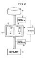
- Fig. 2 is a block diagram illustrating the interior of a partial image area designating unit provided in the image alignment device of Fig. 1;
- Fig. 3 is a block diagram depicting a detailed circuit configuration of a misalignment detecting unit provided in the image alignment device of Fig. 1; and
- Fig. 4 is a block diagram showing the interior of a misalignment correcting unit provided in the image alignment device of Fig. 1.
- With reference to Fig. 1, an automatic image alignment system according to one embodiment of the present invention will now be described. Fig. 1 exemplifies main units of the image alignment device and a process sequence of image data associated with these units.
- In Fig. 1, a pair of
picture images images image area designator 14 which specifies desiredpartial image areas 10a, 12a in therespective images partial image areas 10a, 12a are selected so as to include a characteristic that is relatively clear for detecting the overall misalignment of theimage pair - According to this embodiment, the
partial image areas 10a, 12a are specified by visual comparison by an operator as follows. - The partial
image area designator 14 comprises a display terminal 16 for image display (see Fig. 2). When the operator inputs an instruction to display theimages keyboard 18, theimages image filing unit 20 incorporating a recording medium such as a magnetic disk. Theimages display controller 22. As shown in Fig. 2, theimages keyboard 18 to move rectangular cursors K1 and K2 on the screen to desired locations (thepartial image areas 10a, 12a) on theimages cursor controller 24 connected to thekeyboard 18. Each cursor has the same area as to-be-selected partial image areas. Consequently, the areas on thepicture images partial image areas 10a, 12a. This permits the operator to extract desired partial image areas on the associatedimages - The
partial image areas 10a, 12a, designated by the partialimage area designator 14, are supplied to aprocessor unit 30 where each partial image area is divided into a plurality of image units or segments. For this function, theprocessor unit 30 is called a partial image area divider hereafter. The image segments (n x m segments) of thepartial image area 10a are expressed by "Pnm," and those of the partial image area 12a are expressed by "Qnm." Those segments are affixed with matrix coordinates, which are used to manage each pair of corresponding image segments which are included in the respectivepartial image areas 10a, 12a. - Again in Fig. 1, a
misalignment detecting unit 40 is located at the subsequent stage of the partialimage area divider 30. Themisalignment detecting unit 40 comprises asegment pair designator 42 and a misalignment calculatingunit 44. Thesegment pair designator 42 sequentially designates segment pairs, one from each partial image area (10a, 12a), e.g., P₁₁ and Q₁₁, P₁₂ and Q₁₂, ..., Pij and Qij. Themisalignment calculating unit 44 computes a misalignment vector between each designated segment pair, for exmaple, Pij and Qij. This computation is based on an evaluation function with two different parameters, a correlation coefficient between the corresponding image segments Pij, Qij and a pixel density difference coefficient that is the sum of the absolute value of the difference in pixel densities between corresponding portions of the designated segment pair. (These parameters are hereafter called correlation data and pixel density difference data.) The misalignment vector for the first image segment pair, P₁₁ and Q₁₁, is calculated based on the evaluation function, and is supplied to a memory (to be described later). Then, the next image segment pair, e.g., P₁₂ and Q₁₂, is specified by thesegment pair designator 42. The misalignment vector for this segment pair is calculated by the calculatingunit 44 and is stored in the memory. The same calculation process is executed for every one of the associated image segment pairs, thus providing a plurality of misalignment vector data for the partial image areas (10a, 12a). These plural pieces of misalignment vector data are supplied to an imageposition correcting unit 50, which extracts reliable ones from the vector data for overall alignment of thepicture images unit 50 can also partially correct the picture images with a divided picture segment of an image plane used as a unit, as desired. - Fig. 3 is a detailed illustration of the interior of the
misalignment detecting unit 40. Thesegment pair designator 42 is connected to aninitial address memory 60 and addresscontrollers memory 60 stores center addresses of thepartial image areas 10a, 12a. The address controller 62 (Pij address controller) stores data of the sizes (unit areas) of image segments Pij of thepartial image area 10a and center addresses of the individual segments. The other address controller 64 (Qij address controller) stores center address data and size data of image segments Qij of the partial image area 12a. - The Pij address controller 62 is coupled to a Pij
image segment memory 68 through afirst image memory 66, which stores thefirst image picture 10. Based on the address data, the pij address controller 62 reads out the image picture from thefirst image memory 66 and extracts a specific image segment Pij. The extracted image segment Pij is stored in theimage segment memory 68. The Qij address controller 64 supplies the size data and central address data of an image segment Qij of thesecond image picture 12 to a neighboring region designator 72 under the control of a coarsemisalignment detecting circuit 70. The neighboring region designator 72 extracts an image segment with the specified size and the specified address being in the center from theimage picture 12 stored in asecond image memory 74. The extracted image segment Qij is stored in a segment memory 76 (Qij image segment memory) coupled to thesecond image memory 74. This pair of image segments Pij and Qij, respectively stored in theimage segment memories - Each of the
image memories calculators calculator 80 sequentially calculates the correlation data, i.e., the first evaluation parameter, while thecalculator 82 sequentially calculates the pixel density difference data (the second evaluation parameter). The image segment information stored in each of theimage memories calculators correlation data memory 84 and a pixeldensity difference memory 86. This data process is repeated for neighboring regions around the image segment designated by the neighboringregion designator 72. That is, while shifting the image segment Qij by a small amount on the image plane around the initial position, the correlation data between the image segment Qij and image segment Pij (stationary) is sequentially calculated. - The
correlation data calculator 80 andcorrelation data memory 84 are included in the coarsemisalignment detecting circuit 70. Thememory 84 is coupled to amaximum detector 90, which detects the maximum correlation data among those stored in thememory 84 and generates anaddress signal 92 representing the center address of the image segment (Qij') having the maximum correlation data. The correlation coefficient between the image segment Pij, and the image segment Qij' within the shifting range of the segment Qij, is maximum. - The
address signal 92 is transmitted to the Qij address controller 64 through a switch 94 that is in a first electrical mode as shown in Fig. 3. The Qij address controller 64 supplies new center address data of the neighbouring image segment Qij' to the neighboring region designator 72 and adisplacement calculator 96, which is coupled to theinitial address memory 60 and the Qij address controller 64. Thedisplacement calculator 96 calculates the displacement between the center address of the initial image segment Qij, stored in theinitial address memory 60, and the center address of the image segment Qij', represented by thesignal 92 obtained in the coarsemisalignment detecting circuit 70. The displacement or displacement vector data between the center addresses of the image segments Qij and Qij' is stored in adisplacement memory 98. Based on the calculated displacement, the Qij address controller 64 supplies the new center address data of the image segment Qij to the neighboringregion designator 72. - The coarse
misalignment detecting circuit 70 includes aswitch controller 100; which detects the maximum (converged) correlation data among the all the correlation data obtained with the image segment Qij being shifted around. At this time, the detectingcircuit 70 controls the switch 94 to prevent the supply of theaddress signal 92 to the Qij address controller 64. In the case where the correlation coefficients between the image segment pair Pij, Qij are sequentially calculated for the segment Qij being shifted, a gradual decrease in a change in the calculated correlation data can mean that the correlation data is approaching (or converging with) the maximum correlation data. When the variation in the correlation data over a period of time falls below a predetermined threshold level, i.e., when the maximum correlation data is converged, theswitch controller 100 switches the switch 94 to end the coarse misalignment detection mode. Theswitch controller 100 serves to maintain the coarse misalignment detection (first misalignment detection) for the image segment pair Pij, Qij as long as the change in the correlation data is above the threshold level. When the change in the correlation data for the image segment pair Pij, Qij decreases to fall below the threshold level, the coarse misalignment detection is completed and the fine misalignment detection (second misalignment detection) starts. In this embodiment, the fine misalignment detection further uses the pixel density difference data (the second evaluation parameter). The following description discusses the arrangement of theswitch controller 100 and explains the fine misalignment detection. - A
variation calculator 102 is connected to themaximum detector 90 to sequentially calculate temporal changes in the maximum coefficient data for the associated image segment pair. The obtained data of the temporal changes in the maximum coefficient data is supplied to a data comparator 104 connected to athreshold value generator 106 that prestores thethreshold value 108. The comparator 104 compares thereference threshold value 108 with the variation in the maximum correlation data that is an actual value. When the variation becomes smaller than the threshold value, the comparator 104 supplies a changeover instruction signal to aswitch driver 110, which is connected to the switch 94. In response to this signal, theswitch driver 110 switches the switch 94 from the first electrical mode to a second electrical mode, which prevents theaddress signal 92 of the coarsemisalignment detecting circuit 70 from passing the switch 94. This completes the coarse misalignment detection. - Suppose the evaluation parameter or evaluation function used in the fine misalignment detection is represented by "P(xy)" which is given by:
P(xy) = S(xy) - kx·E(xy), - where S(xy):
- data obtained by normalizing the correlation data calculated in the
correlation data calculator 80, - E(xy):
- data obtained by normalizing the pixel density difference data,
- x, y:
- coordination on the image plane,
- kx:
- weighing parameter (positive).
- Two
normalizer circuits correlation data calculator 80 and pixel densitydifference data calculator 82. Thenormalizers calculators normalizers subtractor circuit 116, which performs a subtraction on s(xy) and E(xy) to obtain the evaluation function P(xy) for fine misalignment detection. Thus attained P(xy) is stored, together with the center address (X, Y) of the corresponding neighboring region, in amemory 118 located at the succeeding stage of thesubtractor 116. - This process of obtaining P(xy) is repeated wherein one image segment Qij' of the image segment pair, the coarse alignment detection of which has been completed, is finely shifted on the same image plane under the control of the Qij address controller. Plural pieces of evaluation function data P(xy) obtained in each process are sequentially stored in the
memory 118. A secondmaximum detector 120 coupled to thememory 118 detects the maximum one, P(xy)max, among the stored P(xy) and generates asecond address signal 122 representing the center address of an image segment Qij'' which has yielded P(xy)max. Thisaddress signal 122 is fed back to the Qij address controller 64 via the switch 94 in the second electrical mode. Like in the coarse misalignment detection mode, thedisplacement calculator 96 calculates the displacement between the initial center address and the center address of the image segment Qij''. - The
maximum detector 120 is connected to acomparator 124 connected to athreshold value generator 126, which prestores athreshold value 128 for the evaluation function. Thecomparator 124 compares thethreshold value 128 with evaluation function data that is an actual value. When the change in the actual evaluation function data increases to rise above the threshold value, it can be considered that a final matching between the associated image segments Pij, Qij" has substantially occurred. Thus, thecomparator 124 supplies a misalignmentdetection end signal 132 to aswitch driver 130 connected to the switch 94. In response to thesignal 132. the switch 94 changes to the original electrical mode from the second electrical mode. This completed the fine misalignment detection and makes the image processing device ready for the coarse misalignment detection for the next image segment pair. for example. Pi+1,j and Qi+1,j. - The
switch driver 130, operable in the fine alignment detection mode, is coupled to three transmission switches S1, S2, S3. The first data transmission switch S1 is provided between thecorrelation data memory 84 and final (converged)correlation data memory 140 having correlation data relating to each optimum Qi,j'. Thismemory 140 exclusively stores final correlation data (converged in the coarse misalignment detection mode) with address data specifying the image segment pair which has yielded the final correlation data. The second data transmission switch S2 is provided between the pixel densitydifference data memory 86 and a final (converged) pixel densitydifference data memory 142 having pixel density data relating to each optimum Qij". Thememory 142 exclusively stores converged pixel density difference data, which is also affixed with address data specifying the image segment pair that has yielded that pixel density difference data. The third data transmission switch S3 is provided between thedisplacement memory 98 and finalmisalignment data memory 144. Thismemory 144 exclusively stores misalignment vector data finally yielded through the coarse and fine misalignment detection modes. This misalignment vector data is also affixed with address data specifying the image segment pair which has yielded that particular vector data. These switches S1, S2, S3 become conductive in response to the misalignmentdetection end signal 132 from theswitch driver 130. Therefore, upon completion of the fine misalignment detection, all the final data is stored in thememories - The misalignment detection for the next image segment pair, e.g., Pi+1,j and Qi+1,j, is also carried out in two steps; namely, the coarse and fine misalignment detection modes. These two steps are repeated for every corresponding image segment pair of the
partial image areas 10a, 12a. As a result, regional misalignment vector data for every image segment pair (P₁₁, Q₁₁), ..., (Pij, Qij), ..., (Pnm, Qnm) can be obtained. - The image
position correcting unit 50 determines an optimum alignment for thepicture images unit 50. - Fig. 4 is a detailed illustration of the interior of the
position correcting unit 50. Theposition correcting unit 50 includes a reliable misalignmentdata search circuit 148 which searches plural pieces of misalignment vector data, obtained by repeating the misalignment detection for all the image segment pairs, for the one with the highest reliability. As shown in Fig. 4, thesearch circuit 148 includes two sortingcircuits correlation data memory 140 and the converged pixel densitydifference data memory 142. Thesorting circuit 150 receives plural pieces of converged or final correlation data for plural pieces of image segment pairs Pij, Qij and sorts the correlation data in order from the largest to the smallest, thus providing a hierarchical sequential organization. Consequently, the correlation data is stored in ahierarchic memory 154, located at the succeeding stage of thesorting circuit 150, in order from the largest to the smallest. This forms a hierarchic structure for the plural pieces of correlation data obtained for the corresponding image segment pairs Pij, Qij of thepartial image areas 10a, 12a. Theother sorting circuit 152 receives plural pieces of converged or final pixel density difference data for the same plural pieces of image segment pairs Pij, Qij and sorts the pixel density difference data in order from the smallest to the largest. Therefore, the pixel density difference data is stored in anotherhierarchic memory 156, located at the succeeding stage of thesorting circuit 152, in order from the smallest to the largest. This forms a hierarchic structure for the plural pieces of pixel density difference data obtained for the corresponding image segment pairs Pij, Qij of thepartial image areas 10a, 12a. - An AND
circuit 158, coupled to thehierarchic memories hierarchic memories memories hierarchic memory 154 and the pixel density difference data ranked as the third in thehierarchic memory 156, this pair is also selected because the misalignment vector of such a pair is considered to have a relatively high reliability. An image segment pair with the best correlation data or pixel density difference data but the other data being ranked below the fifth would not be selected. For example, an image segment pair with the best correlation data but with the seventh rank pixel density difference data would not be selected. Amemory 160 coupled to the ANDcircuit 158 exclusively stores the positions in thehierarchic memories - A position-adjusting address controller 162 is coupled to the final
misalignment data memory 144 shown in Fig. 3. This controller 162 finds out the position data of the image segment pair (or pairs) having the highly-reliable misalignament data stored in thememory 160 and accesses thememory 144 to extract the final or converged misalignment data that is actually calculated for the concerned image segment pair (or pairs). Based on the reliable misalignment data, the address controller 162, which is also coupled to theimage memories partial image areas 10a, 12a are regions of interest for a medical examination, a fine misalignment compensation can be performed on thoseimage areas 10a and 12a. When the misalignment between the original image pictures is considered uniform over the entire picture plane, the overall alignment of the image pictures 10, 12 can be accurately carried out based on the mean vector of the selected reliable misalignment data. - According to the imaging system incorporating the image alignment apparatus embodying the present invention, first, desired
partial image areas 10a, 12a, which interest an operator or include clear properties, are extracted from a pair of targets, i.e., image pictures 10, 12. Each of the extractedareas 10a, 12a is divided into a plurality of image segments arranged in a matrix form. An arbitrary pair of segments (Pij, Qij) corresponding to each other is selected from among these image segments and the misalignment vector between the pair is then calculated. After the misalignment vector calculation is completed for one image segment pair, a final misalignment vector is stored in thememory 144. Then, the same misalignment vector calculation is taken with the next image segment pair until all the image segment pairs are involved. - It should be noted that the misalignment detection for each pair of corresponding image segments is performed in two steps. The first step is the coarse misalignment detection mode in which the detection is carried out based on the correlation data for the image segment pair calculated as one of the pair is shifted around on the image plane. The second step is the fine misalignment detection mode in which the detection is carried out based on the evaluation function P(xy) and further depending on the pixel density difference data between the image segment pair. These two steps, involving not only the correlation data but also the pixel density difference data as two evaluation parameters, will yield significantly reliable final misalignment vector information. The coarse detection mode is switched to the fine mode when the variation in the correlation data updated in the coarse
misalignment detecting circuit 70 falls below a specific reference level or threshold level. Such a level is set by thethreshold value generator 106 included in the coarsemisalignment detecting circuit 70. - It can be said that the matching of the image segment pair has been approximately detected at the time the correlation data between the pair reaches the threshold level. Therefore, the misalignment vector can be obtained by calculating the displacement between the center coordinations of the image segments. However, the present invention does not stop the detection at this stage but goes further into a finer misalignment detection. A new evaluation function based on the correlation data and pixel density difference data is introduced in the fine detection mode, thus ensuring finer detection of alignment between the associated image segment pair. The above-discussed point is one important technical feature of the present invention.
- Another important feature resides in that one piece of misalignment vector data with a significantly high reliability is selected from the plural pieces of misalignment vector data obtained by repeating the aforementioned detection procedures for every image segment pair. The correlation data and pixel density difference data of each image segment pair are separately sorted to search for an image segment pair (or pairs) with good characteristics in both data. The segment pair or pairs are extracted as being significantly reliable. As a result, an accuracy in detecting regional misalignment vectors between the
partial image areas 10a, 12a, i.e., regions of interest, can further be improved. Therefore, even when the misalignment vector between medical-purpose picture images or satellite-transmitted images is uniform over the entire image plane, accurate alignment can be realized for at least a part of a region of interest. Further, even when noise is included in thepartial image areas 10a, 12a, the process of selecting image segment pairs with high reliability can exclude those with lower reliability resulting from noise. This provides a highly accurate and reliable image alignment process which is substantially free of adverse noise effects. This further improves image synthesis. Thus, the image position alignment technique of the present invention can significantly contribute to image synthesis used in medical purposes, satellite-image processing, etc. - Although the present invention has been shown and described with reference to a particular embodiment, various changes and modifications which are obvious to any persons skilled in the art to which the invention pertains are deemed to lie within the scope of the invention.
- For example, the evaluation function for specifying the quantity of a misalignment may be a combination of other indices than the correlation coefficient and pixel density difference which also represent the quantity image alignment. In the aforementioned embodiment, the information of pixel densities is used for the correlation coefficient and pixel density difference. However, when a distinctive common characteristic is obviously seen between two image pictures, the alignment process can be performed paying attention only to that characteristic. In addition, the misalignment vector quantity obtained for each pair of partial image areas with high reliability may be used directly to correct the image position of that particular pair, thus aligning the associated image pictures segment by segment.
The greater S(xy) or the smaller E(xy) is, the greater thus the defined function P(xy) becomes. P(xy) has a maximum of 1.0 only when the image segment pair matches ideally.
Claims (11)
- An image processing apparatus for aligning a pair of first and second picture images, comprising first processor means (14) for extracting a desired partial image area from each of the first and second images to be subjected to position alignment, and second processor means (30) for dividing each of said partial image areas into n x m image segments (Pij, Qij) arranged in a matrix form, where n and m are positive integers, characterized in that said apparatus further comprises:
third processor means (40):
in a first mode, for selecting an initial image segment (Pij) of the first image;
for detecting misalignment between said initial image segment (Pij) and a number of image segments (Qij) of said second image using a first evaluation parameter based upon correlation coefficient data to select an optimum image segment (Qij') having a given maximum correlation coefficient;
in a second mode, for detecting misalignment between said initial image segment (Pij) and a number of image segments finely shifted about said optimum image segment (Qij') using a second evaluation parameter based upon pixel density difference data and correlation coefficient data to select the optimum image segment pair (Pij, Qij'') having a maximum evaluation function (Pxy);
for selecting a further initial image segment (Pi+j, j) and repeating said detection in said first and second mode;
for storing misalignment data for each (Pij); and fourth processor means (50) for selecting at least one optimum image segment pair (Pij, Qij'') having the optimum misalignment data and for aligning said first and second picture images based upon said optimum misalignment data. - The apparatus according to claim 1, characterized in that said third processor means comprises:
first calculator means (80) for sequentially calculating said correlation coefficient data, when said first detection mode is carried out, by shifting at least one of said corresponding image segment pairs around an initial position on an image plane in a manner such that each shifting from said initial position makes the image segments before and after the shifting have some overlapping portions therebetween; and
first maximum detector means (90) for determining the maximum correlation data among plural pieces of said correlation data calculated for each pair of said corresponding image segments. - The apparatus according to claim 2, characterized in that said third processor means further comprises:
mode controller means (100), connected to said first maximum detector means (90), for electrically storing a threshold value of said correlation data and switching the detection mode from said first detection mode to said second detection mode when a variation in the correlation data between said image segment pairs, sequentially detected, decreases to fall below said threshold value. - The apparatus according to claim 3, characterized in that said third processor means further comprises:
second calculator means (82) for summing the magnitudes of pixel density differences for each of said image segment pairs in said second detection mode to produce said pixel density difference data;
normalizer means (112, 114), connected to said first calculator means (80) and second calculator means (82), for normalizing said correlation data and pixel density difference data; and
third calculator means (116), connected to said normalizer means (112, 114), for calculating said second evaluation parameter based on said normalized correlation data and pixel density difference data. - The apparatus according to claim 4, characterized in that said third processor means further comprises:
second maximum detector means (120) for updating said second evaluation parameter to determine the maximum among a plurality of said second evaluation parameters calculated for the particular image segment pair;
mode termination means (124, 130), coupled to said second maximum detector means (120), for electrically storing a threshold value of said second evaluation parameter and terminating said second detection mode performed for the particular image segment pair by said third processor means (40) when said updated second evaluation parameter exceeds said threshold value; and
fourth calculator means (96) for detecting center addresses of each of said optimum image segment pairs and calculating a misalignment between said center addresses. - The apparatus according to claim 5, characterized by further comprising fifth processor means (148) for sorting final correlation data and pixel density difference data, which are respectively obtained in said first and second detection modes for said particular and said optimum image segment pairs of said partial image areas, for searching all of said particular and optimum image segment pairs for at least one image segment pair having both correlation data and pixel density difference data highly ranked and for calculating a misalignment vector between said at least one image segment pair.
- The apparatus according to claim 6, characterized in that said fifth processor means (148) comprises:
a first hierarchic memory (154) for storing said plural pieces of final correlation data for all of said particular image segment pairs in order from the largest to the smallest;
a second hierarchic memory (156) for storing said plural pieces of final pixel density difference data for all of said optimum image segment pairs in order from the smallest to the largest; and
circuit means (158, 160, 162), coupled to said first and second hierarchic memories, for extracting at least one image segment pair with the correlation data and pixel density difference data both being in a specific high rank and for specifying misalignment vector data of said at least one image segment pair. - An image processing method for aligning a pair of first and second picture images, comprising the steps of extracting a desired partial image area from each of the first and second picture images to be aligned, and dividing each of said partial image areas into n x m image segments (Pij, Qij) arranged in a matrix form, where n x m are positive integers, characterised by further comprising the steps of:
in a first mode, selecting an initial image segment (Pij) of the first image;
detecting misalignment between said initial image segment (Pij) and a number of image segments (Qij) of said second image using a first evaluation parameter based upon correlation coefficient data to select an optimum image segment (Qij') having a given maximum correlation coefficient;
in a second mode, detecting misalignment between said initial image segment (Pij) and a number of image segments finely shifted about said optimum image segment (Qij') using a second evaluation parameter based upon pixel density difference data and correlation coefficient data to select the optimum image segment pair (Pij, Qij'') having a maximum evaluation function (Pxy);
selecting a further initial image segment (Pi+1, j) and repeating said detection in said first and second mode;
storing misalignment data for each (Pij); and
selecting at least one optimum image segment pair (Pij, Qij'') having the optimum misalignment data and for aligning said first and second picture images based upon said optimum misalignment data. - The method according to claim 8, characterised by further comprising a step of repeatedly performing said first and second misalignment detections for the image segment pairs other than said selected image segment pair, thus providing final misalignment vector data for all of said n x m image segment pairs included in said partial image areas of said first and second images.
- The method according to claim 9, characterized by further comprising the steps of:
separately sorting plural pieces of final correlation data and pixel density difference data obtained for all of said image segment pairs;
searching said all of said image segment pairs for at least one image segment pair having those correlation data and pixel density difference data which are both in a predetermined high rank; and
specifying the misalignment quantity between said at least one image segment pair as highly reliable misalignment data and utilizing said specified misalignment quantity for aligning said first and second images. - The method according to claim 9, characterized by further comprising the steps of:
sorting said final correlation data in order from the largest to the smallest to form a hierarchic structure for said correlation data;
sorting said final pixel density difference data in order from the smallest to the largest to form a hierarchic structure for said pixel density difference data;
searching all of said image segment pairs for at least one image segment pair having those correlation data and pixel density difference data which are both in a predetermined high rank; and
specifying the misalignment quantity between said at least one image segment pair as highly reliable misalignment data and utilizing said specified misalignment quantity for aligning said first and second images.
Applications Claiming Priority (2)
| Application Number | Priority Date | Filing Date | Title |
|---|---|---|---|
| JP59033581A JP2531605B2 (en) | 1984-02-24 | 1984-02-24 | Image registration device |
| JP33581/84 | 1984-02-24 |
Publications (3)
| Publication Number | Publication Date |
|---|---|
| EP0154404A2 EP0154404A2 (en) | 1985-09-11 |
| EP0154404A3 EP0154404A3 (en) | 1987-09-23 |
| EP0154404B1 true EP0154404B1 (en) | 1991-06-12 |
Family
ID=12390488
Family Applications (1)
| Application Number | Title | Priority Date | Filing Date |
|---|---|---|---|
| EP85300648A Expired EP0154404B1 (en) | 1984-02-24 | 1985-01-30 | Processing system for aligning two picture images |
Country Status (4)
| Country | Link |
|---|---|
| US (1) | US4635293A (en) |
| EP (1) | EP0154404B1 (en) |
| JP (1) | JP2531605B2 (en) |
| DE (1) | DE3583162D1 (en) |
Cited By (10)
| Publication number | Priority date | Publication date | Assignee | Title |
|---|---|---|---|---|
| US7889263B2 (en) | 2000-10-12 | 2011-02-15 | Amnis Corporation | System and method for high numeric aperture imaging systems |
| US7925069B2 (en) | 1999-01-25 | 2011-04-12 | Amnis Corporation | Blood and cell analysis using an imaging flow cytometer |
| US8005314B2 (en) | 2005-12-09 | 2011-08-23 | Amnis Corporation | Extended depth of field imaging for high speed object analysis |
| US8103080B2 (en) | 2004-03-16 | 2012-01-24 | Amnis Corporation | Method for imaging and differential analysis of cells |
| US8131053B2 (en) | 1999-01-25 | 2012-03-06 | Amnis Corporation | Detection of circulating tumor cells using imaging flow cytometry |
| US8150136B2 (en) | 2004-03-16 | 2012-04-03 | Amnis Corporation | Image based quantitation of molecular translocation |
| US8406498B2 (en) | 1999-01-25 | 2013-03-26 | Amnis Corporation | Blood and cell analysis using an imaging flow cytometer |
| US8451524B2 (en) | 2009-09-29 | 2013-05-28 | Amnis Corporation | Modifying the output of a laser to achieve a flat top in the laser's Gaussian beam intensity profile |
| US8817115B1 (en) | 2010-05-05 | 2014-08-26 | Amnis Corporation | Spatial alignment of image data from a multichannel detector using a reference image |
| US8953866B2 (en) | 2004-03-16 | 2015-02-10 | Amnis Corporation | Method for imaging and differential analysis of cells |
Families Citing this family (72)
| Publication number | Priority date | Publication date | Assignee | Title |
|---|---|---|---|---|
| DE3584718D1 (en) * | 1984-12-07 | 1992-01-02 | Dainippon Screen Mfg | IMAGE DATA PROCESSING METHOD AND SYSTEM DAFUER. |
| US4789934A (en) * | 1986-01-21 | 1988-12-06 | International Business Machines Corporation | Signature verification algorithm |
| DE3604111A1 (en) * | 1986-02-10 | 1987-10-15 | Nukem Gmbh | METHOD AND DEVICE FOR DETECTING DEFECTS IN AN OBJECT |
| JPS62186381A (en) * | 1986-02-12 | 1987-08-14 | Hitachi Ltd | Picture alignment system |
| US4858128A (en) * | 1986-08-11 | 1989-08-15 | General Electric Company | View-to-view image correction for object motion |
| US4949391A (en) * | 1986-09-26 | 1990-08-14 | Everex Ti Corporation | Adaptive image acquisition system |
| NL8603059A (en) * | 1986-12-01 | 1988-07-01 | Philips Nv | DEVICE AND METHOD WITH MOTION ARTEFACT REDUCTION FOR DIFFERENCE IMAGE DETERMINATION. |
| US4882629A (en) * | 1987-05-08 | 1989-11-21 | Everex Ti Corporation | Adaptive exposure control system |
| JPH02100583A (en) * | 1988-10-07 | 1990-04-12 | Toshiba Corp | Method and device for aligning picture |
| JP2557510B2 (en) * | 1988-12-29 | 1996-11-27 | 株式会社東芝 | Personal authentication device |
| FR2645300B1 (en) * | 1989-03-29 | 1994-09-09 | Gen Electric Cgr | AUTOMATIC IMAGE RECORDING PROCESS |
| US5133020A (en) * | 1989-07-21 | 1992-07-21 | Arch Development Corporation | Automated method and system for the detection and classification of abnormal lesions and parenchymal distortions in digital medical images |
| DE69032837T2 (en) * | 1989-09-22 | 1999-05-12 | Fuji Photo Film Co Ltd | Method and device for energy subtraction processing, method and device for superposition processing, and device for radiation image reading |
| US5146102A (en) * | 1990-02-22 | 1992-09-08 | Kabushiki Kaisha Toshiba | Fingerprint image input apparatus including a cylindrical lens |
| JP2745764B2 (en) * | 1990-03-08 | 1998-04-28 | 松下電器産業株式会社 | Position recognition device |
| NL9000766A (en) * | 1990-04-02 | 1991-11-01 | Koninkl Philips Electronics Nv | DEVICE FOR GEOMETRIC CORRECTION OF A DISTRIBUTED IMAGE. |
| US5214711A (en) * | 1990-08-24 | 1993-05-25 | Board Of Regents Of The University Of Oklahoma | Method and apparatus for detecting and quantifying motion of a body part |
| CA2051939A1 (en) * | 1990-10-02 | 1992-04-03 | Gary A. Ransford | Digital data registration and differencing compression system |
| JPH04207866A (en) * | 1990-11-30 | 1992-07-29 | Toshiba Corp | Image processor |
| US5913822A (en) * | 1991-09-25 | 1999-06-22 | Siemens Medical Systems, Inc. | Optimization of parameters in nuclear medicine studies before the studies are concluded |
| US5495535A (en) * | 1992-01-31 | 1996-02-27 | Orbotech Ltd | Method of inspecting articles |
| CA2100324C (en) * | 1992-08-06 | 2004-09-28 | Christoph Eisenbarth | Method and apparatus for determining mis-registration |
| US5550937A (en) * | 1992-11-23 | 1996-08-27 | Harris Corporation | Mechanism for registering digital images obtained from multiple sensors having diverse image collection geometries |
| CA2114986A1 (en) * | 1993-02-08 | 1994-08-09 | Robert T. Frankot | Automatic subarea selection for image registration |
| DE69420168T2 (en) * | 1993-03-30 | 2000-04-06 | Koninkl Philips Electronics Nv | X-ray examination device with an image forming device with several image sensors |
| WO1995014348A1 (en) * | 1993-11-16 | 1995-05-26 | International Business Machines Corporation | Method and apparatus for alignment of images for template elimination |
| US5483606A (en) * | 1994-01-03 | 1996-01-09 | Xerox Corporation | Method for automatically registering a document having a plurality of pages |
| US5742701A (en) * | 1994-02-15 | 1998-04-21 | Matsushita Electric Industrial Co., Ltd. | Alignment detection apparatus |
| EP0693739A3 (en) * | 1994-07-13 | 1997-06-11 | Yashima Denki Kk | Method and apparatus capable of storing and reproducing handwriting |
| US5687259A (en) * | 1995-03-17 | 1997-11-11 | Virtual Eyes, Incorporated | Aesthetic imaging system |
| JP4114959B2 (en) * | 1995-06-20 | 2008-07-09 | キヤノン株式会社 | Image processing method and apparatus |
| AU1983397A (en) * | 1996-02-29 | 1997-09-16 | Acuson Corporation | Multiple ultrasound image registration system, method and transducer |
| US5876345A (en) * | 1997-02-27 | 1999-03-02 | Acuson Corporation | Ultrasonic catheter, system and method for two dimensional imaging or three-dimensional reconstruction |
| US6045508A (en) * | 1997-02-27 | 2000-04-04 | Acuson Corporation | Ultrasonic probe, system and method for two-dimensional imaging or three-dimensional reconstruction |
| JP2856207B1 (en) * | 1997-09-10 | 1999-02-10 | 日本電気株式会社 | Image position adjusting device and computer readable recording medium storing image position adjusting program |
| US6549899B1 (en) * | 1997-11-14 | 2003-04-15 | Mitsubishi Electric Research Laboratories, Inc. | System for analyzing and synthesis of multi-factor data |
| EP0994442A3 (en) * | 1998-06-17 | 2002-08-21 | Her Majesty The Queen In Right Of Canada As Represented By The Minister Of National Defence | A method for tracking organ motion and removing artifacts for computed tomography imaging systems |
| US20060257884A1 (en) * | 2004-05-20 | 2006-11-16 | Amnis Corporation | Methods for preparing and analyzing cells having chromosomal abnormalities |
| US7057732B2 (en) * | 1999-01-25 | 2006-06-06 | Amnis Corporation | Imaging platform for nanoparticle detection applied to SPR biomolecular interaction analysis |
| US6975400B2 (en) * | 1999-01-25 | 2005-12-13 | Amnis Corporation | Imaging and analyzing parameters of small moving objects such as cells |
| US8885913B2 (en) | 1999-01-25 | 2014-11-11 | Amnis Corporation | Detection of circulating tumor cells using imaging flow cytometry |
| US6535570B2 (en) * | 1999-06-17 | 2003-03-18 | Her Majesty The Queen In Right Of Canada, As Represented By The Minister Of National Defence Of Her Majesty's Canadian Government | Method for tracing organ motion and removing artifacts for computed tomography imaging systems |
| US6741738B2 (en) | 2000-03-13 | 2004-05-25 | Tms, Inc. | Method of optical mark recognition |
| US6934408B2 (en) * | 2000-08-25 | 2005-08-23 | Amnis Corporation | Method and apparatus for reading reporter labeled beads |
| US6875973B2 (en) * | 2000-08-25 | 2005-04-05 | Amnis Corporation | Auto focus for a flow imaging system |
| US6738532B1 (en) * | 2000-08-30 | 2004-05-18 | The Boeing Company | Image registration using reduced resolution transform space |
| CA2445960A1 (en) * | 2001-02-21 | 2002-12-19 | Amnis Corporation | Method and apparatus for labeling and analyzing cellular components |
| AU2002308693A1 (en) * | 2001-04-25 | 2002-11-05 | Amnis Corporation | Method and apparatus for correcting crosstalk and spatial resolution for multichannel imaging |
| US7190832B2 (en) * | 2001-07-17 | 2007-03-13 | Amnis Corporation | Computational methods for the segmentation of images of objects from background in a flow imaging instrument |
| US20050025347A1 (en) * | 2001-12-28 | 2005-02-03 | Sherif Makram-Ebeid | Medical viewing system having means for image adjustment |
| JP4169185B2 (en) * | 2002-02-25 | 2008-10-22 | 富士通株式会社 | Image linking method, program, and apparatus |
| WO2004026139A1 (en) * | 2002-09-17 | 2004-04-01 | Fujitsu Limited | Biological information acquiring apparatus and authentication apparatus using biological information |
| US7610942B2 (en) * | 2003-01-15 | 2009-11-03 | Amnis Corporation | Cell suspension rotating fluidic pump |
| JP4276042B2 (en) * | 2003-10-07 | 2009-06-10 | パイオニア株式会社 | INDEX DATA GENERATION DEVICE, INDEX DATA GENERATION METHOD, INDEX DATA GENERATION PROGRAM AND INFORMATION RECORDING MEDIUM CONTAINING THE SAME, CONTENT DATA REPRODUCTION DEVICE, CONTENT DATA REPRODUCTION METHOD, CONTENT DATA REPRODUCTION PROGRAM, AND INFORMATION RECORDING MEDIUM CONTAINING THE SAME |
| JP2005253684A (en) * | 2004-03-11 | 2005-09-22 | Konica Minolta Medical & Graphic Inc | Medical image processing system and medical image processing method |
| US7773799B2 (en) * | 2004-04-02 | 2010-08-10 | The Boeing Company | Method for automatic stereo measurement of a point of interest in a scene |
| US20060215935A1 (en) * | 2004-04-02 | 2006-09-28 | The Boeing Company | System and architecture for automatic image registration |
| US7751651B2 (en) * | 2004-04-02 | 2010-07-06 | The Boeing Company | Processing architecture for automatic image registration |
| US8055100B2 (en) * | 2004-04-02 | 2011-11-08 | The Boeing Company | Method and system for image registration quality confirmation and improvement |
| US20050285947A1 (en) * | 2004-06-21 | 2005-12-29 | Grindstaff Gene A | Real-time stabilization |
| US7653264B2 (en) | 2005-03-04 | 2010-01-26 | The Regents Of The University Of Michigan | Method of determining alignment of images in high dimensional feature space |
| US7580591B2 (en) * | 2005-07-01 | 2009-08-25 | The Boeing Company | Method for generating a synthetic perspective image |
| US7873240B2 (en) * | 2005-07-01 | 2011-01-18 | The Boeing Company | Method for analyzing geographic location and elevation data and geocoding an image with the data |
| US8194946B2 (en) * | 2005-07-28 | 2012-06-05 | Fujifilm Corporation | Aligning apparatus, aligning method, and the program |
| JP5061543B2 (en) * | 2006-09-05 | 2012-10-31 | 大日本印刷株式会社 | Printed matter inspection device, printed matter inspection method |
| US20080095414A1 (en) * | 2006-09-12 | 2008-04-24 | Vladimir Desh | Correction of functional nuclear imaging data for motion artifacts using anatomical data |
| US8098956B2 (en) | 2007-03-23 | 2012-01-17 | Vantana Medical Systems, Inc. | Digital microscope slide scanning system and methods |
| US20090027417A1 (en) * | 2007-07-24 | 2009-01-29 | Horsfall Joseph B | Method and apparatus for registration and overlay of sensor imagery onto synthetic terrain |
| US20100226926A1 (en) * | 2009-03-09 | 2010-09-09 | Bioimagene, Inc | Method of Detection of Fluorescence-Labeled Probes Attached to Diseased Solid Tissue |
| US8537181B2 (en) * | 2009-03-09 | 2013-09-17 | Ventana Medical Systems, Inc. | Modes and interfaces for observation, and manipulation of digital images on computer screen in support of pathologist's workflow |
| WO2019138469A1 (en) * | 2018-01-10 | 2019-07-18 | 株式会社Fuji | Work machine and method for determining polarity |
| JP6776317B2 (en) * | 2018-12-21 | 2020-10-28 | キヤノン株式会社 | Image processing equipment, image processing methods and programs |
Family Cites Families (9)
| Publication number | Priority date | Publication date | Assignee | Title |
|---|---|---|---|---|
| US3905045A (en) * | 1973-06-29 | 1975-09-09 | Control Data Corp | Apparatus for image processing |
| JPS5650308B2 (en) * | 1974-09-18 | 1981-11-27 | ||
| JPS52140278A (en) * | 1976-05-19 | 1977-11-22 | Hitachi Ltd | Position detector |
| US4200861A (en) * | 1978-09-01 | 1980-04-29 | View Engineering, Inc. | Pattern recognition apparatus and method |
| JPS57137978A (en) * | 1981-02-20 | 1982-08-25 | Toshiba Corp | Pattern detecting device |
| JPS57196366A (en) * | 1981-05-28 | 1982-12-02 | Nec Corp | Picture positioning device |
| JPS5886659A (en) * | 1981-11-18 | 1983-05-24 | Toshiba Corp | Positioning device for picture |
| JPS5952359A (en) * | 1982-09-02 | 1984-03-26 | Hitachi Medical Corp | Automatic corrector for picture distortion during inter-picture operation |
| US4521909A (en) * | 1983-10-04 | 1985-06-04 | Wang Laboratories, Inc. | Dual level pattern recognition system |
-
1984
- 1984-02-24 JP JP59033581A patent/JP2531605B2/en not_active Expired - Fee Related
-
1985
- 1985-01-30 US US06/696,491 patent/US4635293A/en not_active Expired - Lifetime
- 1985-01-30 DE DE8585300648T patent/DE3583162D1/en not_active Expired - Lifetime
- 1985-01-30 EP EP85300648A patent/EP0154404B1/en not_active Expired
Cited By (16)
| Publication number | Priority date | Publication date | Assignee | Title |
|---|---|---|---|---|
| US8660332B2 (en) | 1999-01-25 | 2014-02-25 | Amnis Corporation | Blood and cell analysis using an imaging flow cytometer |
| US8009189B2 (en) | 1999-01-25 | 2011-08-30 | Amnis Corporation | Extended depth of field imaging for high speed object analysis |
| US8406498B2 (en) | 1999-01-25 | 2013-03-26 | Amnis Corporation | Blood and cell analysis using an imaging flow cytometer |
| US8131053B2 (en) | 1999-01-25 | 2012-03-06 | Amnis Corporation | Detection of circulating tumor cells using imaging flow cytometry |
| US7925069B2 (en) | 1999-01-25 | 2011-04-12 | Amnis Corporation | Blood and cell analysis using an imaging flow cytometer |
| US8379136B2 (en) | 2000-10-12 | 2013-02-19 | Amnis Corporation | System and method for high numeric aperture imaging systems |
| US7889263B2 (en) | 2000-10-12 | 2011-02-15 | Amnis Corporation | System and method for high numeric aperture imaging systems |
| US8150136B2 (en) | 2004-03-16 | 2012-04-03 | Amnis Corporation | Image based quantitation of molecular translocation |
| US8103080B2 (en) | 2004-03-16 | 2012-01-24 | Amnis Corporation | Method for imaging and differential analysis of cells |
| US8571294B2 (en) | 2004-03-16 | 2013-10-29 | Amnis Corporation | Method for imaging and differential analysis of cells |
| US8571295B2 (en) | 2004-03-16 | 2013-10-29 | Amnis Corporation | Method for imaging and differential analysis of cells |
| US8824770B2 (en) | 2004-03-16 | 2014-09-02 | Amnis Corporation | Method for imaging and differential analysis of cells |
| US8953866B2 (en) | 2004-03-16 | 2015-02-10 | Amnis Corporation | Method for imaging and differential analysis of cells |
| US8005314B2 (en) | 2005-12-09 | 2011-08-23 | Amnis Corporation | Extended depth of field imaging for high speed object analysis |
| US8451524B2 (en) | 2009-09-29 | 2013-05-28 | Amnis Corporation | Modifying the output of a laser to achieve a flat top in the laser's Gaussian beam intensity profile |
| US8817115B1 (en) | 2010-05-05 | 2014-08-26 | Amnis Corporation | Spatial alignment of image data from a multichannel detector using a reference image |
Also Published As
| Publication number | Publication date |
|---|---|
| JP2531605B2 (en) | 1996-09-04 |
| US4635293A (en) | 1987-01-06 |
| EP0154404A2 (en) | 1985-09-11 |
| EP0154404A3 (en) | 1987-09-23 |
| DE3583162D1 (en) | 1991-07-18 |
| JPS60178582A (en) | 1985-09-12 |
Similar Documents
| Publication | Publication Date | Title |
|---|---|---|
| EP0154404B1 (en) | Processing system for aligning two picture images | |
| US5845009A (en) | Object tracking system using statistical modeling and geometric relationship | |
| US5529069A (en) | Magnetic resonance imaging apparatus | |
| US6915003B2 (en) | Method and apparatus for matching positions of images | |
| US5359513A (en) | Method and system for detection of interval change in temporally sequential chest images | |
| US4644582A (en) | Image registration method | |
| US6445832B1 (en) | Balanced template tracker for tracking an object image sequence | |
| US5907626A (en) | Method for object tracking and mosaicing in an image sequence using a two-dimensional mesh | |
| CN108665457A (en) | Image-recognizing method, device, storage medium and computer equipment | |
| US7120277B2 (en) | Segmentation unit for and method of determining a second segment and image processing apparatus | |
| US20090278991A1 (en) | Method for interpolating a previous and subsequent image of an input image sequence | |
| JP2002511617A (en) | Face recognition from video images | |
| JPH1023452A (en) | Picture extracting device and its method | |
| JPH07168943A (en) | Device and method for generating motion vector field by exclusion of local abnormality | |
| JPH1040392A (en) | Device for tracing local area image | |
| Olsen | Stereo correspondence by surface reconstruction | |
| JP2961264B1 (en) | Three-dimensional object model generation method and computer-readable recording medium recording three-dimensional object model generation program | |
| EP0125130B1 (en) | X-ray image correction apparatus | |
| Suh et al. | Knowledge-based system for boundary detection of four-dimensional cardiac magnetic resonance image sequences | |
| Duncan | Knowledge directed left ventricular boundary detection in equilibrium radionuclide angiocardiography | |
| US4783831A (en) | Method for producing a standard pattern for pattern matching | |
| JP3505872B2 (en) | Moving object tracking device in image | |
| JPH09130714A (en) | Image information extracting device and method | |
| US6483949B1 (en) | Image processing apparatus and method, and medium therefor | |
| CN112188075B (en) | Snapshot, image processing device and image processing method |
Legal Events
| Date | Code | Title | Description |
|---|---|---|---|
| PUAI | Public reference made under article 153(3) epc to a published international application that has entered the european phase |
Free format text: ORIGINAL CODE: 0009012 |
|
| 17P | Request for examination filed |
Effective date: 19850206 |
|
| AK | Designated contracting states |
Designated state(s): DE FR GB NL |
|
| PUAL | Search report despatched |
Free format text: ORIGINAL CODE: 0009013 |
|
| RHK1 | Main classification (correction) |
Ipc: G06F 15/68 |
|
| AK | Designated contracting states |
Kind code of ref document: A3 Designated state(s): DE FR GB NL |
|
| 17Q | First examination report despatched |
Effective date: 19890323 |
|
| GRAA | (expected) grant |
Free format text: ORIGINAL CODE: 0009210 |
|
| AK | Designated contracting states |
Kind code of ref document: B1 Designated state(s): DE FR GB NL |
|
| PG25 | Lapsed in a contracting state [announced via postgrant information from national office to epo] |
Ref country code: NL Effective date: 19910612 |
|
| REF | Corresponds to: |
Ref document number: 3583162 Country of ref document: DE Date of ref document: 19910718 |
|
| ET | Fr: translation filed | ||
| NLV1 | Nl: lapsed or annulled due to failure to fulfill the requirements of art. 29p and 29m of the patents act | ||
| PLBE | No opposition filed within time limit |
Free format text: ORIGINAL CODE: 0009261 |
|
| STAA | Information on the status of an ep patent application or granted ep patent |
Free format text: STATUS: NO OPPOSITION FILED WITHIN TIME LIMIT |
|
| 26N | No opposition filed | ||
| PGFP | Annual fee paid to national office [announced via postgrant information from national office to epo] |
Ref country code: FR Payment date: 19970109 Year of fee payment: 13 |
|
| PGFP | Annual fee paid to national office [announced via postgrant information from national office to epo] |
Ref country code: GB Payment date: 19970121 Year of fee payment: 13 |
|
| PGFP | Annual fee paid to national office [announced via postgrant information from national office to epo] |
Ref country code: DE Payment date: 19970207 Year of fee payment: 13 |
|
| PG25 | Lapsed in a contracting state [announced via postgrant information from national office to epo] |
Ref country code: GB Free format text: LAPSE BECAUSE OF NON-PAYMENT OF DUE FEES Effective date: 19980130 |
|
| PG25 | Lapsed in a contracting state [announced via postgrant information from national office to epo] |
Ref country code: FR Free format text: THE PATENT HAS BEEN ANNULLED BY A DECISION OF A NATIONAL AUTHORITY Effective date: 19980131 |
|
| GBPC | Gb: european patent ceased through non-payment of renewal fee |
Effective date: 19980130 |
|
| PG25 | Lapsed in a contracting state [announced via postgrant information from national office to epo] |
Ref country code: DE Free format text: LAPSE BECAUSE OF NON-PAYMENT OF DUE FEES Effective date: 19981001 |
|
| REG | Reference to a national code |
Ref country code: FR Ref legal event code: ST |