EP0151020A2 - Surgical instrument - Google Patents
Surgical instrument Download PDFInfo
- Publication number
- EP0151020A2 EP0151020A2 EP85300577A EP85300577A EP0151020A2 EP 0151020 A2 EP0151020 A2 EP 0151020A2 EP 85300577 A EP85300577 A EP 85300577A EP 85300577 A EP85300577 A EP 85300577A EP 0151020 A2 EP0151020 A2 EP 0151020A2
- Authority
- EP
- European Patent Office
- Prior art keywords
- instrument
- barrel
- blade
- blades
- instrument according
- Prior art date
- Legal status (The legal status is an assumption and is not a legal conclusion. Google has not performed a legal analysis and makes no representation as to the accuracy of the status listed.)
- Withdrawn
Links
Images


Classifications
-
- A—HUMAN NECESSITIES
- A61—MEDICAL OR VETERINARY SCIENCE; HYGIENE
- A61B—DIAGNOSIS; SURGERY; IDENTIFICATION
- A61B10/00—Other methods or instruments for diagnosis, e.g. instruments for taking a cell sample, for biopsy, for vaccination diagnosis; Sex determination; Ovulation-period determination; Throat striking implements
- A61B10/02—Instruments for taking cell samples or for biopsy
- A61B10/0291—Instruments for taking cell samples or for biopsy for uterus
Definitions
- the pateted instrument It is known from my Canadian Palent No. 614, 878 which issued on February 21st 1961, to provide a surgical instrument (hereinafter termed "the pateted instrument") for collecting tissue cells for use as specimens for cytological diagnosis, in particular, the detection of cancer of the cervix and uterus.
- thermoplastic material in the manufacture of uterine cell collectors, it is practical to manufacture disposable cell collectors, which are sterilized and sealed in an ultra-clean environment. The examining physician is then able to remove the pre-sterilized instrument from its container, use it, and dispose of it, without being concerned that the used instrument will either spread bacteria in the surgery or pass any communicable disease to the next patient.
- the use of such plastic materials in manufacturing a uterine cell collector thereby serves not only to ensure complete and uniform cleanliness of the cell collector, but also compensates for the inefficiencies and time involved in in-surgery sterilization, and the onerous possiblility that a physician's sterilization equipment might malfunction.
- the object of the present invention is to provide such a surgical instrument that will overcome the above disadvantages and yet, will be relatively inexpensive to manufacture and of simple construction.
- the present invention relates to a surgical instrument for collecting tissue cells for use as specimens for cytological diagnosis, said instrument being of the type having an elongated barrel provided with a pair of exterior scraping blades the longitudinal axes of which extend substantially normal to one another, and a plunger sLidable within said barrel, said blades and said plunger being utilized for said collection, characterized in that (a) the instrument is disposale, being formed from thermoplastic material; (b) the longitudinal axis of the scraping edge of one of said blades extends at an angle of between 14 and 16 to the longitudinal axis of the scraping edge of the remaining
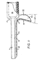
- Figure 11 is an alternative embodiment of the barrel member.
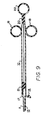
- the invention basically consists of two components i.e. an elongated barrel member shown in some detail in Figures 1 to 4 and a plunger member shown in some detail in Figures 5 to 7 and 9, both members being formed from thermoplastic material.
- the elongated barrel member or cylinder 10 has its intracervical portion 11 considerably reduced in diameter and is provided with a first or endocervical scraping blade (indicated generally at 13) extending throughout its length having a longitudinal axis, said first blade gradually merging into a second or portio vaginalis scraping blade, indicated generally at 14, projecting from adjacent the distal end of the barrel 10.
- the operative edge 15 (shown more clearly in Figure 3a) of the first blade 13 extends parallel with the longitudinal axis of said distal end 11 whereas the operative edge 16 of the second blade 14 extends at an angle of between 14 and 16 ( Figures 1 - 3) to the longitudinal axis of blade 14 and is, in fact, preferably at an angle of 15.
- the operatives edges 15, 16 of the scraping blades 13, 14 respectively each serve as a forward boundary wall of an associated cell collection area, 15a, 16a respectively, the purpose of which will be described hereinafter.
- the longitudinal axes of the blades 13 and 14 extend substantially normal to one another.
- the distal end of the barrel is inwardly curved towards its intracervical portion so as to accommodate that portion of said portio vaginalis in frictional contact therewith.
- distal end of the barrel 10 is inwardly curved, as at 17, towards said intracervical portion 11.
- said proximal and of the barerl member 10 is provided with a pair of diametrically opposed finger-rings 18.
- FIG. 5 - 7 which illustrate the preferred form of the plunger member, indicated generally at 20, its major length has a cross-section which is substantially cruciform in cross-section which can be more easily seen from Figure 6.
- the distal end of the plunger member 20 is provided with a slightly domed plunger head 21 which is adapted to be in slidable frictional contact with the inner periphery of the barrel member 10 while its proximal end is provided with a thumb-grip 22.
- the major length of the plunger member 20 could be of substantially triangular cross-section as is shown in Figure 9.
- the completely assembled surgical instrument is shown in partial longitudinal section in Figure 9.
- the operation of the instrument is such that the examining physician first exposes the cervix with a vaginal speculum. The distal end of the instrument is then inserted into the vagina so that the end portion 11, as well as the first blade 13, is located within the cervical canal of the uterus, the said end portion 11 being adjacent to the internal os of the cervix. At the same time, the second blade 14 is thus located adjacent to, and gently engaging, the portio vaginal is of the cervix. The physician then, as was the case in the patented instrument, rotates the instrument.
- the operative edge 15 of the first blade 13 obtains a comprehensive sampling of cells from the endocervix which arc deposited on cell collection area 15a.
- the operative edge 16 of the second blade 14 obtains a representative sampling of cells from the squamocol umnar junction and the adjacent surface of the portio vaginalis and which cells arc deposited on cell collection area 16a.
- FIG. 10 shows diagrammatically the position of the instrument and its relation to the uterus and cervix when samples are required to be taken from the three locations just mentioned.
- the plunger 20 is depressed forcefully so that its domed head 21 ejects the said cellular debris from the barrel to enable a smear to be made and, of course, the said scrapings are removed from the collection areas 15a and 16a so as to enable similar smears to be made when they are dropped into a fixative solution and prepared for cytologic examination.
- blades 13 and 14 are shown in Figures 1-4 and 9 and 10 as non-serrated, if desired, their operative edges may be serrated as is shown in greater detail in Figure 11.
- the instrument is preferably moulded from any suitable thermoplastic material such as, for example, both high and low density polyethylene, or polypropylene, or acrylonitrile-butadiene-styrene (A.B.S. resin), rubber-modified polystyrene, cellulose acetate, or cellulose acetate butyrate.
- suitable thermoplastic material such as, for example, both high and low density polyethylene, or polypropylene, or acrylonitrile-butadiene-styrene (A.B.S. resin), rubber-modified polystyrene, cellulose acetate, or cellulose acetate butyrate.
Abstract
The invention relates to a two-piece disposable surgical instrument for collecting tissue cells for use as specimens for cytological diagnosis, in particular, the detection of cancer of the cervix and uterus.
Each part of the instrument is moulded from thermoplastic material. One part consists of a barrel having a reduced end having two finger rings at the other. The reduced end has a pair of scraping blades, portions of which serve as forward walls of cell collection areas.
The remaining part of the instrument consists of a plunger slidable within the barrel and having a thumb-grip, the plunger being capable of collecting and ejecting cells from the barrel and obtained from a different area of the cervix to those areas from which the pair of blades obtained their εells.
Description
- It is known from my Canadian Palent No. 614, 878 which issued on February 21st 1961, to provide a surgical instrument (hereinafter termed "the pateted instrument") for collecting tissue cells for use as specimens for cytological diagnosis, in particular, the detection of cancer of the cervix and uterus.
- While the patented instrument has, in all respect, been admirable for the above purpose, one of the major drawbacks accompanying the use of metals - even stainless steel - in surgical instruments is the absolute necessity of sterilizing the instruments between uses. Furthermore, the instruments must also be sterilized immediately prior to use. Therefore, it is often necessary to sterilize the same instrument twice - once after use, to prevent the spread of bacteria in surgery, and again immediately prior to use to ensure that the patient is not exposed to any extraneous source of bacteria.
- It is therefore necessary to maintain highly specialized, expensive sterilization equipment in a surgery, if metal instruments are to be used. It is also necessary to maintain a supply of these expensive instruments to ensure the smooth operation of a surgery.
- Another drawback particularly associated with known metallic uterine cell collection instruments is the difficulty in ensuring that the rubber scal ing rings of the plunger and the surrounding metallic areas are properly sterilized. These rings must also be periodically replaced because of wear.
- I have found that by utilizing thermoplastic material in the manufacture of uterine cell collectors, it is practical to manufacture disposable cell collectors, which are sterilized and sealed in an ultra-clean environment. The examining physician is then able to remove the pre-sterilized instrument from its container, use it, and dispose of it, without being concerned that the used instrument will either spread bacteria in the surgery or pass any communicable disease to the next patient. The use of such plastic materials in manufacturing a uterine cell collector thereby serves not only to ensure complete and uniform cleanliness of the cell collector, but also compensates for the inefficiencies and time involved in in-surgery sterilization, and the onerous possiblility that a physician's sterilization equipment might malfunction.
- The object of the present invention, therefore, is to provide such a surgical instrument that will overcome the above disadvantages and yet, will be relatively inexpensive to manufacture and of simple construction.
- Accordingly, the present invention relates to a surgical instrument for collecting tissue cells for use as specimens for cytological diagnosis, said instrument being of the type having an elongated barrel provided with a pair of exterior scraping blades the longitudinal axes of which extend substantially normal to one another, and a plunger sLidable within said barrel, said blades and said plunger being utilized for said collection, characterized in that (a) the instrument is disposale, being formed from thermoplastic material; (b) the longitudinal axis of the scraping edge of one of said blades extends at an angle of between 14 and 16 to the longitudinal axis of the scraping edge of the remaining
- Figure 11 is an alternative embodiment of the barrel member.
- Referring to the drawings, the invention basically consists of two components i.e. an elongated barrel member shown in some detail in Figures 1 to 4 and a plunger member shown in some detail in Figures 5 to 7 and 9, both members being formed from thermoplastic material.
- Referring specifically to Figures 1 to 4, the elongated barrel member or
cylinder 10 has itsintracervical portion 11 considerably reduced in diameter and is provided with a first or endocervical scraping blade (indicated generally at 13) extending throughout its length having a longitudinal axis, said first blade gradually merging into a second or portio vaginalis scraping blade, indicated generally at 14, projecting from adjacent the distal end of thebarrel 10. The operative edge 15 (shown more clearly in Figure 3a) of thefirst blade 13 extends parallel with the longitudinal axis of saiddistal end 11 whereas theoperative edge 16 of thesecond blade 14 extends at an angle of between 14 and 16 (Figures 1 - 3) to the longitudinal axis ofblade 14 and is, in fact, preferably at an angle of 15. - As will be seen more clearly from reference to Figures 3 and 3a the
operatives edges scraping blades blades - blade so as to obtain maximal approximation of the cutting edge of said one blade to the medial portion of the portio vaginal is that communicates with the endocervical canal; and (c) the distal end of the barrel is inwardly curved towards its intracervical portion so as to accommodate that portion of said portio vaginalis in frictional contact therewith.
- The invention is illustrated, by way of example, in the accompanying drawings in which:
- Figure 1 is a longitudinal view of the barrel member;
- Figure 2 is a plan view of Figure 1;
- Figure 3 is a detailed view, on an enlarged scale, of the distal end of the barrel member;
- Figure 3a is a detailed cross-section, on an enlarged scale, of one of the scraping blades;
- Figure 4 is an end view of Figure 3;
- Figure 5 is a longitudinal view of the plunger member;
- Figure 6 is a transverse section, on an enlarged scale, taken on the line VI - VI of Figure 5;
- Figure 7 is a detailed view, on an enlarged scale, of the distal end of the plunger member:
- Figure 8 is an alternative embodiment of the plunger member;
- Figure 9 is a longitudinal section of the assembled instrument;
- Figure 10 is a diagrammatic view of the surgical instrument and its relation to the cervix during collection of tissue cells; and
- It will also be seen that the distal end of the
barrel 10 is inwardly curved, as at 17, towards saidintracervical portion 11. Moreover, said proximal and of thebarerl member 10 is provided with a pair of diametrically opposed finger-rings 18. - Referring now to Figures 5 - 7 which illustrate the preferred form of the plunger member, indicated generally at 20, its major length has a cross-section which is substantially cruciform in cross-section which can be more easily seen from Figure 6. The distal end of the
plunger member 20 is provided with a slightlydomed plunger head 21 which is adapted to be in slidable frictional contact with the inner periphery of thebarrel member 10 while its proximal end is provided with a thumb-grip 22. If desired, the major length of theplunger member 20 could be of substantially triangular cross-section as is shown in Figure 9. - The completely assembled surgical instrument is shown in partial longitudinal section in Figure 9.
- The operation of the instrument is such that the examining physician first exposes the cervix with a vaginal speculum. The distal end of the instrument is then inserted into the vagina so that the
end portion 11, as well as thefirst blade 13, is located within the cervical canal of the uterus, the saidend portion 11 being adjacent to the internal os of the cervix. At the same time, thesecond blade 14 is thus located adjacent to, and gently engaging, the portio vaginal is of the cervix. The physician then, as was the case in the patented instrument, rotates the instrument. forming the subject of instant application clockwise through 360 with continuous pressure upon the entire wall of the cervical canal and the vaginal portio so that theoperative edge 15 of thefirst blade 13 obtains a comprehensive sampling of cells from the endocervix which arc deposited oncell collection area 15a. Simultaneously, theoperative edge 16 of thesecond blade 14 obtains a representative sampling of cells from the squamocol umnar junction and the adjacent surface of the portio vaginalis and which cells arc deposited oncell collection area 16a. Immediately prior Lo the complete withdrawal of the instrument, the operator suddenly applies traction to theplunger member 20 by means of the thumb-grip 22, whereby thedomed plunger head 21 sucks cellular debris and mucus from the uterine cavity above the level of the internal os of the cervix into the interior of theintracervical portion 11 of the barrel member. Figure 10 shows diagrammatically the position of the instrument and its relation to the uterus and cervix when samples are required to be taken from the three locations just mentioned. - After the instrument has been withdrawn from the patient, the
plunger 20 is depressed forcefully so that itsdomed head 21 ejects the said cellular debris from the barrel to enable a smear to be made and, of course, the said scrapings are removed from thecollection areas - Although,
blades - From experience, it has been fourd that the preferred angle of 15 of the
second blade 14 approximates far more to the natural surface angle or contour of the portio vaginalis than did that of the similiar blade of the patented instrument thus giving a much improved surface engagement. - The instrument is preferably moulded from any suitable thermoplastic material such as, for example, both high and low density polyethylene, or polypropylene, or acrylonitrile-butadiene-styrene (A.B.S. resin), rubber-modified polystyrene, cellulose acetate, or cellulose acetate butyrate.
Claims (6)
1. A surgical instrument for collecting tissue cells for use as specimens for cytological diagnosis, said instrument being of the type having an elongated barrel provided with a pair of exterior scraping blades the longitudinal axes of which extend substantially normal to one another, and a plunger slidable within said barrel, said blades and said plunger being utilized for said collection, characterized in that:
(a) the instrument is disposable, being formed from thermoplastic material;
(b) the longitudinal axis of the scraping edge of one of said blades extends at an angle of between 14 and 16 to the longitudinal axis of the scraping edge of the remaining blade so as to obtain maximal approximation of the scraping edge of said one blade to the medial portion of the portio vaginalis that communicates with the endocervical canal; and
(c) the distal end of the barrel is inwardly curved towards its intracervical portion so as to accommodate that portion of said portio vaginalis in frictional contact therewith.
2. An instrument according to Claim 1 wherein the operative edge of each said blades serves as a forward boundary wall of an associated cell collection area.
3. An instrument according to Claim 2 wherein the operative edge of each said blade is planar.
4. An instrument according to Claim 2 wherein the operative edge of each said blade is serrated.
5. An instrument according to Claim 2 wherein said thermoplastic material is selected from the group consisting of high and low density polyethylene, or polypropylene, or acrylonitrile-butadiene-styrene (A.B.S. resin), rubber-modified polystyrene, cellulose acetate, or cellulose acetate butyrate.
6. An instrument according to Claim 5 formed of a moulded thermoplastic material.
Applications Claiming Priority (2)
| Application Number | Priority Date | Filing Date | Title |
|---|---|---|---|
| CA446355 | 1984-01-30 | ||
| CA000446355A CA1237619A (en) | 1984-01-30 | 1984-01-30 | Surgical instrument, namely uterine cell collector |
Publications (2)
| Publication Number | Publication Date |
|---|---|
| EP0151020A2 true EP0151020A2 (en) | 1985-08-07 |
| EP0151020A3 EP0151020A3 (en) | 1985-08-21 |
Family
ID=4127061
Family Applications (1)
| Application Number | Title | Priority Date | Filing Date |
|---|---|---|---|
| EP85300577A Withdrawn EP0151020A3 (en) | 1984-01-30 | 1985-01-29 | Surgical instrument |
Country Status (5)
| Country | Link |
|---|---|
| EP (1) | EP0151020A3 (en) |
| JP (1) | JPS60179054A (en) |
| KR (1) | KR910009412B1 (en) |
| CA (1) | CA1237619A (en) |
| IE (1) | IE850206L (en) |
Cited By (4)
| Publication number | Priority date | Publication date | Assignee | Title |
|---|---|---|---|---|
| WO1988003393A1 (en) * | 1986-11-03 | 1988-05-19 | The Cooper Companies, Inc. | Small incision intraocular lens with adjustable power |
| EP0448137A1 (en) * | 1990-01-23 | 1991-09-25 | J. Van Brunschot B.V. | Device for simultaneously taking samples from the endocervix and the exocervix |
| WO1992014396A1 (en) * | 1991-02-15 | 1992-09-03 | Baxter International Inc. | Disposable cervical dilators |
| US7832613B2 (en) | 2009-01-15 | 2010-11-16 | General Electric Company | Friction stir welding system |
Citations (6)
| Publication number | Priority date | Publication date | Assignee | Title |
|---|---|---|---|---|
| US3088454A (en) * | 1960-01-06 | 1963-05-07 | Wallace B Shute | Surgical instrument |
| US3626928A (en) * | 1970-06-22 | 1971-12-14 | Becton Dickinson Co | Intrauterine washing apparatus |
| US3774590A (en) * | 1970-04-01 | 1973-11-27 | B Mcdonald | Uterine specimen collecting method |
| DE2829118A1 (en) * | 1978-07-03 | 1980-01-17 | Zeppelin Dieter Von | Womb cancer diagnostic appts. - has balloon tube filling lumen and inserted through neck from vagina using catheter |
| US4245653A (en) * | 1979-01-02 | 1981-01-20 | Kenneth Weaver | Method and apparatus for obtaining specimens of endometrial tissue |
| US4384587A (en) * | 1980-08-18 | 1983-05-24 | Milex Products, Inc. | Spatula for collecting cervical cancer cells |
-
1984
- 1984-01-30 CA CA000446355A patent/CA1237619A/en not_active Expired
-
1985
- 1985-01-29 IE IE850206A patent/IE850206L/en unknown
- 1985-01-29 EP EP85300577A patent/EP0151020A3/en not_active Withdrawn
- 1985-01-30 JP JP60016366A patent/JPS60179054A/en active Pending
- 1985-01-30 KR KR1019850000573A patent/KR910009412B1/en not_active IP Right Cessation
Patent Citations (6)
| Publication number | Priority date | Publication date | Assignee | Title |
|---|---|---|---|---|
| US3088454A (en) * | 1960-01-06 | 1963-05-07 | Wallace B Shute | Surgical instrument |
| US3774590A (en) * | 1970-04-01 | 1973-11-27 | B Mcdonald | Uterine specimen collecting method |
| US3626928A (en) * | 1970-06-22 | 1971-12-14 | Becton Dickinson Co | Intrauterine washing apparatus |
| DE2829118A1 (en) * | 1978-07-03 | 1980-01-17 | Zeppelin Dieter Von | Womb cancer diagnostic appts. - has balloon tube filling lumen and inserted through neck from vagina using catheter |
| US4245653A (en) * | 1979-01-02 | 1981-01-20 | Kenneth Weaver | Method and apparatus for obtaining specimens of endometrial tissue |
| US4384587A (en) * | 1980-08-18 | 1983-05-24 | Milex Products, Inc. | Spatula for collecting cervical cancer cells |
Cited By (4)
| Publication number | Priority date | Publication date | Assignee | Title |
|---|---|---|---|---|
| WO1988003393A1 (en) * | 1986-11-03 | 1988-05-19 | The Cooper Companies, Inc. | Small incision intraocular lens with adjustable power |
| EP0448137A1 (en) * | 1990-01-23 | 1991-09-25 | J. Van Brunschot B.V. | Device for simultaneously taking samples from the endocervix and the exocervix |
| WO1992014396A1 (en) * | 1991-02-15 | 1992-09-03 | Baxter International Inc. | Disposable cervical dilators |
| US7832613B2 (en) | 2009-01-15 | 2010-11-16 | General Electric Company | Friction stir welding system |
Also Published As
| Publication number | Publication date |
|---|---|
| KR850005264A (en) | 1985-08-24 |
| JPS60179054A (en) | 1985-09-12 |
| KR910009412B1 (en) | 1991-11-15 |
| CA1237619A (en) | 1988-06-07 |
| IE850206L (en) | 1988-07-30 |
| EP0151020A3 (en) | 1985-08-21 |
Similar Documents
| Publication | Publication Date | Title |
|---|---|---|
| US4340066A (en) | Medical device for collecting a body sample | |
| EP0066958B1 (en) | Endometrial sampling device | |
| US4641662A (en) | Endocervical curette system | |
| CA1045492A (en) | Vacuum curet | |
| US4620548A (en) | Pap smear T-zone sampler | |
| US6302853B1 (en) | Method and apparatus for sampling cervical tissue | |
| US6336905B1 (en) | Endocervical sampling device | |
| US20120157878A1 (en) | Anatomically designed and collapsible intravaginal device for self-sampling and containment of cervical epithelial cells | |
| US3776219A (en) | Cervical scraper | |
| AU2001247207A1 (en) | Method and apparatus for sampling cervical tissue | |
| US4168698A (en) | Endocervical strip biopsy instrument | |
| US3774590A (en) | Uterine specimen collecting method | |
| GB2204496A (en) | Device for collecting biological material | |
| US5865765A (en) | Dilator/sampler for sampling materials and fluid from a body cavity | |
| US4054127A (en) | Endometrial sampling instrument | |
| US11571188B1 (en) | Device and method for locating and retaining biopsy sampling device on epithelial tissue | |
| EP0448137A1 (en) | Device for simultaneously taking samples from the endocervix and the exocervix | |
| US20040236247A1 (en) | Endocervical Curette | |
| EP0151020A2 (en) | Surgical instrument | |
| CN209751113U (en) | Rotary cutting type cervix biopsy sampler | |
| CA1164761A (en) | Pap smear t-zone sampler | |
| US5464022A (en) | Endometrial sampler | |
| SU1468514A1 (en) | Curette for sampling | |
| US3327702A (en) | Biopsy knife for cutting a conical specimen | |
| RU87077U1 (en) | GYNECOLOGICAL BRUSH FOR CYTOLOGICAL RESEARCH |
Legal Events
| Date | Code | Title | Description |
|---|---|---|---|
| PUAI | Public reference made under article 153(3) epc to a published international application that has entered the european phase |
Free format text: ORIGINAL CODE: 0009012 |
|
| PUAL | Search report despatched |
Free format text: ORIGINAL CODE: 0009013 |
|
| AK | Designated contracting states |
Designated state(s): AT BE CH DE FR GB IT LI NL SE |
|
| AK | Designated contracting states |
Designated state(s): AT BE CH DE FR GB IT LI NL SE |
|
| STAA | Information on the status of an ep patent application or granted ep patent |
Free format text: STATUS: THE APPLICATION IS DEEMED TO BE WITHDRAWN |
|
| 18D | Application deemed to be withdrawn |
Effective date: 19860422 |