EP0146408A2 - Vehicle lamp assembly - Google Patents
Vehicle lamp assembly Download PDFInfo
- Publication number
- EP0146408A2 EP0146408A2 EP84308886A EP84308886A EP0146408A2 EP 0146408 A2 EP0146408 A2 EP 0146408A2 EP 84308886 A EP84308886 A EP 84308886A EP 84308886 A EP84308886 A EP 84308886A EP 0146408 A2 EP0146408 A2 EP 0146408A2
- Authority
- EP
- European Patent Office
- Prior art keywords
- light
- strips
- absorbing material
- lamp assembly
- lens means
- Prior art date
- Legal status (The legal status is an assumption and is not a legal conclusion. Google has not performed a legal analysis and makes no representation as to the accuracy of the status listed.)
- Withdrawn
Links
- 239000011358 absorbing material Substances 0.000 claims abstract description 24
- 238000000576 coating method Methods 0.000 claims abstract description 5
- 239000011248 coating agent Substances 0.000 claims abstract description 4
- 239000012141 concentrate Substances 0.000 claims abstract description 3
- 239000012780 transparent material Substances 0.000 claims abstract description 3
- 230000015572 biosynthetic process Effects 0.000 claims description 26
- 238000005755 formation reaction Methods 0.000 claims description 26
- 230000004048 modification Effects 0.000 description 4
- 238000012986 modification Methods 0.000 description 4
- 230000003287 optical effect Effects 0.000 description 4
- 230000000694 effects Effects 0.000 description 3
- 238000005286 illumination Methods 0.000 description 3
- 230000000712 assembly Effects 0.000 description 2
- 238000000429 assembly Methods 0.000 description 2
- 239000000463 material Substances 0.000 description 2
- 229920003023 plastic Polymers 0.000 description 2
- 238000005299 abrasion Methods 0.000 description 1
- 230000002411 adverse Effects 0.000 description 1
- 238000004519 manufacturing process Methods 0.000 description 1
- 238000000034 method Methods 0.000 description 1
- 239000004033 plastic Substances 0.000 description 1
Images


Classifications
-
- F—MECHANICAL ENGINEERING; LIGHTING; HEATING; WEAPONS; BLASTING
- F21—LIGHTING
- F21S—NON-PORTABLE LIGHTING DEVICES; SYSTEMS THEREOF; VEHICLE LIGHTING DEVICES SPECIALLY ADAPTED FOR VEHICLE EXTERIORS
- F21S43/00—Signalling devices specially adapted for vehicle exteriors, e.g. brake lamps, direction indicator lights or reversing lights
- F21S43/20—Signalling devices specially adapted for vehicle exteriors, e.g. brake lamps, direction indicator lights or reversing lights characterised by refractors, transparent cover plates, light guides or filters
- F21S43/255—Filters
-
- F—MECHANICAL ENGINEERING; LIGHTING; HEATING; WEAPONS; BLASTING
- F21—LIGHTING
- F21S—NON-PORTABLE LIGHTING DEVICES; SYSTEMS THEREOF; VEHICLE LIGHTING DEVICES SPECIALLY ADAPTED FOR VEHICLE EXTERIORS
- F21S43/00—Signalling devices specially adapted for vehicle exteriors, e.g. brake lamps, direction indicator lights or reversing lights
- F21S43/20—Signalling devices specially adapted for vehicle exteriors, e.g. brake lamps, direction indicator lights or reversing lights characterised by refractors, transparent cover plates, light guides or filters
- F21S43/26—Refractors, transparent cover plates, light guides or filters not provided in groups F21S43/235 - F21S43/255
Definitions
- This invention relates to vehicle lamp assemblies of the type in which the colour of the light to be produced by the lamp cannot readily be perceived when the lamp is not illuminated. This reduces the risk that, in bright sunlight for example, the lamp assembly may appear to be illuminated, when in fact it is not.
- the invention relates to a vehicle lamp assembly comprising a light source, a light transmitting member carrying a plurality of strips formed of a light absorbing material, baffle elements of light absorbing material extending perpendicular to the surface of the light transmitting member towards the light source, each baffle element being aligned with a respective one of the parallel strips and being thinner than its corresponding strip, lens means arranged to concentrate light from the light source between adjacent strips and a colour filter located between the light source and the baffle elements.
- the light-absorbing strips are oriented horizontally but the invention is not restricted to any particular orientation.
- a vehicle lamp assembly of this type is disclosed in our Patent Specification EP-A-0074726.
- the purpose of providing the baffle elements is to intercept off-axis externally originating light, such as sunlight before it reaches the colour filter.
- these baffles have the undesirable effect of reducing the perceived brightness of the lamp, when illuminated when the observer is above or below the horizontal optical axis, for example as the vehicle passes over the crest of a hill.
- the present invention aims to overcome this disadvantage.
- the baffles are formed of transparent material and each baffle has an opaque coating on one of its side faces.
- edges of the baffles facing the light source are of minimal area and consequently provide minimum interference to the light emerging from the lens means before it has been concentrated so as to pass between the strips on the light transmitting member.
- the lamp assembly is preferably provided with secondary lens means arranged to increase the horizontal spread of emitted light in the direction parallel to the length of the strips of light absorbing material.
- Patent Specification No. GB-A-1591013 discloses such secondary lens means formed on an outer light transmitting member, located on the opposite side of the strips of light-absorbing material to the light source. The result of this is that, when the lamp is not illuminated, the strips of light-absorbing material, which determine the appearance of the lamp under these conditions, present an overall milky or watery appearance rather than a sharply defined colour.
- the secondary lens means for increasing the distribution of light emitted by the lamp assembly in directions parallel to the lengths of the strips of light-absorbing material, are located between such strips and the light source.
- the secondary lens means may be combined in a single lens assembly with the primary lens means. Alternatively, they may be formed integrally with the light transmitting member, in which case the strips of light-absorbing material are formed on the opposite surface to that facing the light source.
- both the primary and secondary lens means comprise cylindrical lens formations, those of the primary lens means having their axes parallel to the strips of light-absorbing material and those of the secondary lens means having their axes perpendicular to the strips of light-absorbing material.
- the primary lens means may be provided with prism formations aligned with each of the baffle elements and arranged to direct light from the light source through gaps between adjacent strips of light-absorbing material other than the gaps closest to such baffle element, thereby increasing the distribution of emitted light in the direction perpendicular to the strips of light-absorbing material.
- some of the lens elements of the secondary lens means may have a smaller focal length than the remaining lens elements thereof.
- the ratio of intensity of off-axis illumination to on-access illumination can then be controlled by varying the ratio of the aggregate area of lens elements of shorter focal length to the aggregate area of lens element of longer focal length.
- the lamp shown in Figure 1 comprises a bulb 10, the light 12 from which is collimated by a parabolic reflector 14 so that a parallel beam is incident on a lens member 16 of transparent plastics material coloured in accordance with the required colour of the emitted light.
- the lamp assembly On the opposite side of the lens member 16 to the bulb 10, the lamp assembly has a light transmitting member 18, of clear plastics material, with an array of parallel strips 20 of light-absorbing material located on its outer surface. At least the outwardly facing side of the strips 20 is coloured in accordance with the required appearance of the lamp assembly when the bulb 10 is not illuminated.
- the light transmitting member 18 may be formed with raised zones aligned with each of the strips 20, as illustrated, in order to facilitate application of the strips 20 by a printing process.
- the light transmitting member 18 has a respective rib 22 extending parallel to the optical axis of the lamp assembly.
- the upper surface of each rib 22 has an opaque, preferably black, coating 24.
- the lamp assembly Outside the light transmitting member 18, the lamp assembly has a parallel sided transparent outer cover member 26 which both provides the lamp assembly with a smooth outer surface and protects the strips 20 from abrasion.
- the lens member 16 has cylindrical lens formations 30 on its inner surface oriented with their axes parallel to the strips 20 and each aligned with the gap between adjacent pairs of such strips.
- the foci of the lens element 30 are located slightly outside the plane of the strips 20 with the result that most of the light from the bulb 10 which is incident on the lens member 16 is directed between the strips 20.
- the lens member 16 On its outer surface, the lens member 16 has cylindrical lens formations 32 with their axes oriented perpendicular to the axes of the lens element 30.and with their foci outside the plane of the outer cover member 26.
- the lens elements 32 distribute the light emitted by the lamp assembly in the horizontal direction.
- FIG. 3 and 4 The embodiment illustrated in Figures 3 and 4 is generally similar to the embodiment illustrated in Figures 1 and 2. Corresponding components are denoted by the same reference numberals and will not be described again in detail.
- the embodiment of Figures 3 and 4 has a light transmitting member 36 with the opaque strips 20 on its outer surface but with a flat inner surface.
- the ribs 22 are replaced by an array of transparent horizontal elements 38 which are supported on widely spaced vertically extending support members 40 and to which the opaque coatings 24 are applied.
- the members 38 and 40 may conveniently be moulded together as a single integral component.
- the embodiment of Figures 3 and 4 is identical with the embodiment of Figures 1 and 2.
- the lens member 16 is replaced by a lens member 42 having the horizontally extending cylindrical lens elements 30 on its inner surface but a plane outer surface.
- the light transmitting member 44 has the opaque strips 20 on its outer surface and the ribs 22 projecting from its inner surface.
- the inner surface of the light transmitting member 44 comprises cylindrical lens formations 46 located between the ribs 22 and oriented with their axes perpendicular to the axes of the lens formations 30.
- the lens formations 46 can have a shorter focal length than the lens formations 32 of Figure 1, thereby giving a wider horizontal distribution, but the light transmitting member 44 is a more complex component than the light transmitting member 18 of Figure 1.
- Figures 7 and 8 illustrate a further lamp assembly having a lens member 42 similar to that of Figures 5 and 6.
- its light transmitting member 50 is similar to the light transmitting member 44 of Figures 5 and 6 in that it has cylindrical lens formations 46 on its inner surface, but differs therefrom in that it does not have ribs 22. Instead it has an array of horizontal members similar to those of Figure 3.
- the cylindrical lenses 46 may be replaced by so called “pillow optic" lens elements having curvature in both the horizontal and the vertical directions so as to enhance both the horizontal and vertical distribution of light. Since such lens elements are very close to the strips 20, the proportion of light transmitted is not adversely affected.
- Figure 9 which illustrated a modification of the embodiment shown in Figure 1, the proportion of the light incident on the lens member 16 which passes through the gaps between the strips 26 is increased by providing prism formations 60, 62 in alignment with each of the ribs 22.
- Light 64 incident on the lower surfaces of the the prism formations 60 is deflected upwardly through the gap 66 between adjacent strips 26 next below the rib 22 which is aligned with the prism formation 62.
- light incident on the upper surface of the prism element 62 would be directed through the gap 68 which is next above the rib 22 which is aligned with the prism formation 60.
- This additional light is inclined to the optical axis at a greater angle than most of the light from the main beam 12 collected by the lens formations 30. The result is, therefore, to enhance the vertical distribution of light.
- the horizontal distribution of light from either of the embodiments illustrated in Figures 1 to 4 can be enhanced by providing lens formations 70 between each of the lens formations 32 on the outer surface of the lens elements 16, the lens formations 70 having a shorter focal length than the lens formations 32. Light incident on the lens formations 70 is therefore deflected over a wider angle than that incident on the lens formations 32.
- the ratio of the intensity of off-axis illumination to that on the optical axis can be controlled by varying the relative width of the lens formations 70 and the lens formations 32.
Abstract
Description
- This invention relates to vehicle lamp assemblies of the type in which the colour of the light to be produced by the lamp cannot readily be perceived when the lamp is not illuminated. This reduces the risk that, in bright sunlight for example, the lamp assembly may appear to be illuminated, when in fact it is not.
- More specifically, the invention relates to a vehicle lamp assembly comprising a light source, a light transmitting member carrying a plurality of strips formed of a light absorbing material, baffle elements of light absorbing material extending perpendicular to the surface of the light transmitting member towards the light source, each baffle element being aligned with a respective one of the parallel strips and being thinner than its corresponding strip, lens means arranged to concentrate light from the light source between adjacent strips and a colour filter located between the light source and the baffle elements. Normally, the light-absorbing strips are oriented horizontally but the invention is not restricted to any particular orientation.
- A vehicle lamp assembly of this type is disclosed in our Patent Specification EP-A-0074726. The purpose of providing the baffle elements is to intercept off-axis externally originating light, such as sunlight before it reaches the colour filter. However, it has been found that these baffles have the undesirable effect of reducing the perceived brightness of the lamp, when illuminated when the observer is above or below the horizontal optical axis, for example as the vehicle passes over the crest of a hill. The present invention aims to overcome this disadvantage.
- According to the invention, in a vehicle lamp assembly of the type described above, the baffles are formed of transparent material and each baffle has an opaque coating on one of its side faces.
- The effect of the foregoing is that the edges of the baffles facing the light source are of minimal area and consequently provide minimum interference to the light emerging from the lens means before it has been concentrated so as to pass between the strips on the light transmitting member.
- The lamp assembly is preferably provided with secondary lens means arranged to increase the horizontal spread of emitted light in the direction parallel to the length of the strips of light absorbing material. Patent Specification No. GB-A-1591013 discloses such secondary lens means formed on an outer light transmitting member, located on the opposite side of the strips of light-absorbing material to the light source. The result of this is that, when the lamp is not illuminated, the strips of light-absorbing material, which determine the appearance of the lamp under these conditions, present an overall milky or watery appearance rather than a sharply defined colour.
- According to a preferred embodiment of the present invention, the secondary lens means, for increasing the distribution of light emitted by the lamp assembly in directions parallel to the lengths of the strips of light-absorbing material, are located between such strips and the light source. For convenience of manufacture, the secondary lens means may be combined in a single lens assembly with the primary lens means. Alternatively, they may be formed integrally with the light transmitting member, in which case the strips of light-absorbing material are formed on the opposite surface to that facing the light source.
- Preferably both the primary and secondary lens means comprise cylindrical lens formations, those of the primary lens means having their axes parallel to the strips of light-absorbing material and those of the secondary lens means having their axes perpendicular to the strips of light-absorbing material. In lamp assemblies in accordance with the invention where the number of strips of light-absorbing material is a multiple of the number of baffle elements, the primary lens means may be provided with prism formations aligned with each of the baffle elements and arranged to direct light from the light source through gaps between adjacent strips of light-absorbing material other than the gaps closest to such baffle element, thereby increasing the distribution of emitted light in the direction perpendicular to the strips of light-absorbing material.
- In order to further enhance the distribution of light in the direction parallel to the strips of light-absorbing material, some of the lens elements of the secondary lens means may have a smaller focal length than the remaining lens elements thereof. The ratio of intensity of off-axis illumination to on-access illumination can then be controlled by varying the ratio of the aggregate area of lens elements of shorter focal length to the aggregate area of lens element of longer focal length.
- Embodiments of the invention will now be described, by way of example, with reference to the accompanying drawings in which;
- Figure 1 is a schematic cross-sectional view, taken on a vertical plane, of a lamp assembly in accordance with the invention;
- Figure 2 is a cross-sectional view, taken on the line 2 - 2 in Figure 1;
- Figures 3 and 4 are cross-sectional views, corresponding to Figures 1 and 2 of another a lamp assembly in accordance with the invention;
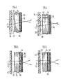
- Figures 5 and 6 are cross-sectional views, corresponding to Figures 1 and 2 of a further embodiment of the invention;
- Figures 7 and 8 are cross-sectional views, similar to Figures 1 and 2 of a further embodiment of the invention;
- Figure 9 is a fragmentary cross-sectional view, on an enlarged scale and taken on a vertical plane, of a modification to the embodiment illustrated in Figure 1;
- Figure 10 is a fragmentary cross-sectional view, on an enlarged scale and taken on a horizontal plane, of another modification of the embodiment illustrated in Figure 1; and
- Figure 11 is a cross-sectional view, similar to Figure 10, of a modification of the embodiment illustrated in Figures 5 and 6.
- The lamp shown in Figure 1 comprises a
bulb 10, thelight 12 from which is collimated by aparabolic reflector 14 so that a parallel beam is incident on alens member 16 of transparent plastics material coloured in accordance with the required colour of the emitted light. - On the opposite side of the
lens member 16 to thebulb 10, the lamp assembly has alight transmitting member 18, of clear plastics material, with an array ofparallel strips 20 of light-absorbing material located on its outer surface. At least the outwardly facing side of thestrips 20 is coloured in accordance with the required appearance of the lamp assembly when thebulb 10 is not illuminated. Thelight transmitting member 18 may be formed with raised zones aligned with each of thestrips 20, as illustrated, in order to facilitate application of thestrips 20 by a printing process. Oppositealternate strips 20, thelight transmitting member 18 has arespective rib 22 extending parallel to the optical axis of the lamp assembly. The upper surface of eachrib 22 has an opaque, preferably black, coating 24. Outside thelight transmitting member 18, the lamp assembly has a parallel sided transparentouter cover member 26 which both provides the lamp assembly with a smooth outer surface and protects thestrips 20 from abrasion. - The
lens member 16 hascylindrical lens formations 30 on its inner surface oriented with their axes parallel to thestrips 20 and each aligned with the gap between adjacent pairs of such strips. The foci of thelens element 30 are located slightly outside the plane of thestrips 20 with the result that most of the light from thebulb 10 which is incident on thelens member 16 is directed between thestrips 20. - On its outer surface, the
lens member 16 hascylindrical lens formations 32 with their axes oriented perpendicular to the axes of the lens element 30.and with their foci outside the plane of theouter cover member 26. Thelens elements 32 distribute the light emitted by the lamp assembly in the horizontal direction. - The embodiment illustrated in Figures 3 and 4 is generally similar to the embodiment illustrated in Figures 1 and 2. Corresponding components are denoted by the same reference numberals and will not be described again in detail. However, in place of the
light transmitting member 18, the embodiment of Figures 3 and 4 has a light transmittingmember 36 with theopaque strips 20 on its outer surface but with a flat inner surface. Theribs 22 are replaced by an array of transparenthorizontal elements 38 which are supported on widely spaced vertically extendingsupport members 40 and to which theopaque coatings 24 are applied. Themembers - In the embodiment illustrated in Figures 5 and 6, the
lens member 16 is replaced by alens member 42 having the horizontally extendingcylindrical lens elements 30 on its inner surface but a plane outer surface. As in Figure 1, the light transmitting member 44 has theopaque strips 20 on its outer surface and theribs 22 projecting from its inner surface. In addition, the inner surface of the light transmitting member 44 comprisescylindrical lens formations 46 located between theribs 22 and oriented with their axes perpendicular to the axes of thelens formations 30. Thelens formations 46 can have a shorter focal length than thelens formations 32 of Figure 1, thereby giving a wider horizontal distribution, but the light transmitting member 44 is a more complex component than thelight transmitting member 18 of Figure 1. - Figures 7 and 8 illustrate a further lamp assembly having a
lens member 42 similar to that of Figures 5 and 6. However, itslight transmitting member 50 is similar to the light transmitting member 44 of Figures 5 and 6 in that it hascylindrical lens formations 46 on its inner surface, but differs therefrom in that it does not haveribs 22. Instead it has an array of horizontal members similar to those of Figure 3. - In either of the embodiments illustrated in Figures 5 to 8, the
cylindrical lenses 46 may be replaced by so called "pillow optic" lens elements having curvature in both the horizontal and the vertical directions so as to enhance both the horizontal and vertical distribution of light. Since such lens elements are very close to thestrips 20, the proportion of light transmitted is not adversely affected. - Turning now to Figure 9, which illustrated a modification of the embodiment shown in Figure 1, the proportion of the light incident on the
lens member 16 which passes through the gaps between thestrips 26 is increased by providingprism formations ribs 22. Light 64 incident on the lower surfaces of the theprism formations 60 is deflected upwardly through thegap 66 betweenadjacent strips 26 next below therib 22 which is aligned with theprism formation 62. Similarly, light incident on the upper surface of theprism element 62 would be directed through thegap 68 which is next above therib 22 which is aligned with theprism formation 60. This additional light is inclined to the optical axis at a greater angle than most of the light from themain beam 12 collected by thelens formations 30. The result is, therefore, to enhance the vertical distribution of light. - Turning now to Figure 10, the horizontal distribution of light from either of the embodiments illustrated in Figures 1 to 4 can be enhanced by providing
lens formations 70 between each of thelens formations 32 on the outer surface of thelens elements 16, thelens formations 70 having a shorter focal length than thelens formations 32. Light incident on thelens formations 70 is therefore deflected over a wider angle than that incident on thelens formations 32. The ratio of the intensity of off-axis illumination to that on the optical axis can be controlled by varying the relative width of thelens formations 70 and thelens formations 32. As illustrated in Figure 11, a similar effect can be achieved with the embodiments illustrated in Figures 5 to 8 by providing short focallength lens formations 74 between each of thelens formations 46 on the light transmitting member 44 of Figures 5 and 6 or thelight transmitting member 50 of Figures 7 and 8.
Claims (8)
Applications Claiming Priority (2)
| Application Number | Priority Date | Filing Date | Title |
|---|---|---|---|
| GB838333924A GB8333924D0 (en) | 1983-12-20 | 1983-12-20 | Vehicle lamp assembly |
| GB8333924 | 1983-12-20 |
Publications (2)
| Publication Number | Publication Date |
|---|---|
| EP0146408A2 true EP0146408A2 (en) | 1985-06-26 |
| EP0146408A3 EP0146408A3 (en) | 1986-06-11 |
Family
ID=10553579
Family Applications (1)
| Application Number | Title | Priority Date | Filing Date |
|---|---|---|---|
| EP84308886A Withdrawn EP0146408A3 (en) | 1983-12-20 | 1984-12-19 | Vehicle lamp assembly |
Country Status (4)
| Country | Link |
|---|---|
| US (1) | US4644455A (en) |
| EP (1) | EP0146408A3 (en) |
| JP (1) | JPS60157102A (en) |
| GB (1) | GB8333924D0 (en) |
Cited By (1)
| Publication number | Priority date | Publication date | Assignee | Title |
|---|---|---|---|---|
| WO2021041329A1 (en) * | 2019-08-30 | 2021-03-04 | Pcms Holdings, Inc. | Creating a 3d multiview display with elastic optical layer buckling |
Families Citing this family (16)
| Publication number | Priority date | Publication date | Assignee | Title |
|---|---|---|---|---|
| US4722023A (en) * | 1984-05-15 | 1988-01-26 | Koito Seisakusho Co., Ltd. | Lamp assembly for emitting a beam of light at an angle to its optical axis |
| JPH01146202A (en) * | 1987-12-01 | 1989-06-08 | Koito Mfg Co Ltd | Vehicle lighting appliance |
| US5684468A (en) * | 1991-05-29 | 1997-11-04 | Kabushiki Kaisha Tokai Rika Denki Seisakusho | Illuminating display device |
| US5149191A (en) * | 1991-12-23 | 1992-09-22 | Ian Lewin | Combination louver/lens light fixture shield |
| US5365412A (en) * | 1993-01-07 | 1994-11-15 | Ford Motor Company | Low profile illuminator |
| US5369554A (en) * | 1993-01-07 | 1994-11-29 | Ford Motor Company | Illuminator utilizing multiple light guides |
| US5471371A (en) * | 1993-01-08 | 1995-11-28 | Ford Motor Company | High efficiency illuminator |
| JP2581778Y2 (en) * | 1993-12-21 | 1998-09-24 | 株式会社小糸製作所 | Vehicle sign lights |
| US5434754A (en) * | 1993-12-27 | 1995-07-18 | Ford Motor Company | Light manifold |
| FR2743405B1 (en) * | 1996-01-10 | 1998-04-03 | Valeo Vision | SIGNAL LIGHT WITH INTERMEDIATE OPTICAL PROCESSING AND STYLE SCREEN AND METHOD FOR MANUFACTURING THE INTERMEDIATE SCREEN |
| JP3904760B2 (en) * | 1999-05-17 | 2007-04-11 | 株式会社小糸製作所 | Vehicle sign light |
| ES1058162Y (en) * | 2004-08-04 | 2005-02-16 | Seat Sa | SIGNALING MODULE FOR OPTICAL VEHICLE GROUPS. |
| US7399106B2 (en) * | 2005-06-13 | 2008-07-15 | Toyota Motor Engineering & Manufacturing North America, Inc. | Lens optics used to reduce part deformation due to heat |
| US20080084705A1 (en) * | 2006-10-09 | 2008-04-10 | Ford Global Technologies, Llc | Vehicle lamp assembly with a one-piece bezel-lens structure |
| US8708527B2 (en) * | 2011-05-17 | 2014-04-29 | Asia Optical Co., Inc. | Light module and optical lens for the light module |
| US20190176686A1 (en) * | 2017-12-11 | 2019-06-13 | American Craft And Design Llc | Motor vehicle light cover |
Citations (7)
| Publication number | Priority date | Publication date | Assignee | Title |
|---|---|---|---|---|
| DE2062472A1 (en) * | 1970-12-18 | 1972-06-22 | Westfaelische Metall Industrie | Signal light for motor vehicles |
| US4153928A (en) * | 1977-11-30 | 1979-05-08 | General Motors Corporation | Motor vehicle tail lamp assembly |
| FR2427549A1 (en) * | 1978-05-30 | 1979-12-28 | Lucas Industries Ltd | LAMP ESPECIALLY WITH REFLECTOR |
| GB2079919A (en) * | 1980-07-10 | 1982-01-27 | Iao Industrie Riunite Spa | Light unit for motor vehicles |
| DE3130085A1 (en) * | 1981-07-30 | 1983-02-17 | Westfälische Metall Industrie KG Hueck & Co, 4780 Lippstadt | Signal lamp for vehicles |
| EP0074726A1 (en) * | 1981-08-29 | 1983-03-23 | Britax Vega Limited | Vehicle lamp assembly |
| FR2525322A1 (en) * | 1982-04-20 | 1983-10-21 | Frankani Sa | Single unit signal camp group for motor vehicle - uses single piece moulding with reflectors and filters for each lamp, with single piece cover having opaque strips |
Family Cites Families (7)
| Publication number | Priority date | Publication date | Assignee | Title |
|---|---|---|---|---|
| US1454671A (en) * | 1922-06-01 | 1923-05-08 | John M Dunlea | Headlight |
| US2341822A (en) * | 1942-02-02 | 1944-02-15 | George H Seal | Nonglare flashlight |
| US2813971A (en) * | 1956-08-14 | 1957-11-19 | Lester D Pickett | Headlight for vehicles |
| US3259776A (en) * | 1963-02-05 | 1966-07-05 | George A Wallace | Sealed beam headlamp with plural optical devices |
| US4158222A (en) * | 1977-09-26 | 1979-06-12 | Gulf & Western Industries, Inc. | Limited visibility signal device |
| ES473582A1 (en) * | 1977-09-29 | 1979-05-01 | Rau Swf Autozubehoer | Signal lamp |
| GB8315518D0 (en) * | 1983-06-07 | 1983-07-13 | Britax Vega Ltd | Vehicle lamp assembly |
-
1983
- 1983-12-20 GB GB838333924A patent/GB8333924D0/en active Pending
-
1984
- 1984-12-17 US US06/682,437 patent/US4644455A/en not_active Expired - Fee Related
- 1984-12-19 EP EP84308886A patent/EP0146408A3/en not_active Withdrawn
- 1984-12-20 JP JP59269590A patent/JPS60157102A/en active Pending
Patent Citations (7)
| Publication number | Priority date | Publication date | Assignee | Title |
|---|---|---|---|---|
| DE2062472A1 (en) * | 1970-12-18 | 1972-06-22 | Westfaelische Metall Industrie | Signal light for motor vehicles |
| US4153928A (en) * | 1977-11-30 | 1979-05-08 | General Motors Corporation | Motor vehicle tail lamp assembly |
| FR2427549A1 (en) * | 1978-05-30 | 1979-12-28 | Lucas Industries Ltd | LAMP ESPECIALLY WITH REFLECTOR |
| GB2079919A (en) * | 1980-07-10 | 1982-01-27 | Iao Industrie Riunite Spa | Light unit for motor vehicles |
| DE3130085A1 (en) * | 1981-07-30 | 1983-02-17 | Westfälische Metall Industrie KG Hueck & Co, 4780 Lippstadt | Signal lamp for vehicles |
| EP0074726A1 (en) * | 1981-08-29 | 1983-03-23 | Britax Vega Limited | Vehicle lamp assembly |
| FR2525322A1 (en) * | 1982-04-20 | 1983-10-21 | Frankani Sa | Single unit signal camp group for motor vehicle - uses single piece moulding with reflectors and filters for each lamp, with single piece cover having opaque strips |
Cited By (2)
| Publication number | Priority date | Publication date | Assignee | Title |
|---|---|---|---|---|
| WO2021041329A1 (en) * | 2019-08-30 | 2021-03-04 | Pcms Holdings, Inc. | Creating a 3d multiview display with elastic optical layer buckling |
| CN114424110A (en) * | 2019-08-30 | 2022-04-29 | Pcms控股公司 | Creating 3D multiview displays with elastic optical layer buckling |
Also Published As
| Publication number | Publication date |
|---|---|
| JPS60157102A (en) | 1985-08-17 |
| EP0146408A3 (en) | 1986-06-11 |
| US4644455A (en) | 1987-02-17 |
| GB8333924D0 (en) | 1984-02-01 |
Similar Documents
| Publication | Publication Date | Title |
|---|---|---|
| US4644455A (en) | Vehicle lamp assembly | |
| EP0122683B1 (en) | Vehicle lamp assembly | |
| KR920001216B1 (en) | Vehicle lamp assemblies | |
| JP3644951B2 (en) | Optically transparent film | |
| US5997156A (en) | Lighting device for generating a rectangular pattern at the work area, E. G. for illuminating pedestrian crossings | |
| US5149191A (en) | Combination louver/lens light fixture shield | |
| CA1248929A (en) | Elongated luminaire | |
| US4538216A (en) | Lighting apparatus | |
| US4525772A (en) | Vehicle lamp assembly | |
| EP0869312A2 (en) | Vehicle signal lamp | |
| US4542448A (en) | Lamp assembly | |
| EP0322370B1 (en) | Rear fog lamp for motor vehicles | |
| EP1831601B1 (en) | Luminaire reflector with light-modifying flange | |
| CA1244390A (en) | Luminaire with lenticular lens | |
| US3725697A (en) | Luminaire comprising means for reducing temperature of exterior refractor | |
| WO1985004944A1 (en) | Motor vehicle lamp, and a light unit for motor vehicles incorporating such lamps | |
| EP0097449B1 (en) | Vehicle lamp assembly | |
| SE8403074D0 (en) | LIGHT DISTRIBUTING LENS | |
| EP0017356B1 (en) | Lens element | |
| JPS62127717A (en) | Liquid crystal display device | |
| GB1581528A (en) | Pedal cycle headlamp | |
| RU2010339C1 (en) | Traffic light section | |
| GB2194321A (en) | Lens system | |
| EP0066438A1 (en) | Improvements to vehicle lamps | |
| CA1200537A (en) | Translucent light control panel |
Legal Events
| Date | Code | Title | Description |
|---|---|---|---|
| PUAI | Public reference made under article 153(3) epc to a published international application that has entered the european phase |
Free format text: ORIGINAL CODE: 0009012 |
|
| AK | Designated contracting states |
Designated state(s): DE FR GB IT SE |
|
| PUAL | Search report despatched |
Free format text: ORIGINAL CODE: 0009013 |
|
| AK | Designated contracting states |
Kind code of ref document: A3 Designated state(s): DE FR GB IT SE |
|
| 17P | Request for examination filed |
Effective date: 19861124 |
|
| 17Q | First examination report despatched |
Effective date: 19880224 |
|
| STAA | Information on the status of an ep patent application or granted ep patent |
Free format text: STATUS: THE APPLICATION IS DEEMED TO BE WITHDRAWN |
|
| 18D | Application deemed to be withdrawn |
Effective date: 19880705 |
|
| RIN1 | Information on inventor provided before grant (corrected) |
Inventor name: INGLIS, PETER JOHN Inventor name: TYSOE, NICHOLAS WILLIAM |