EP0146110A2 - Device for manufacturing cross-grooves on length-wise grooved bottom plates, etc. - Google Patents
Device for manufacturing cross-grooves on length-wise grooved bottom plates, etc. Download PDFInfo
- Publication number
- EP0146110A2 EP0146110A2 EP84115202A EP84115202A EP0146110A2 EP 0146110 A2 EP0146110 A2 EP 0146110A2 EP 84115202 A EP84115202 A EP 84115202A EP 84115202 A EP84115202 A EP 84115202A EP 0146110 A2 EP0146110 A2 EP 0146110A2
- Authority
- EP
- European Patent Office
- Prior art keywords
- drive shaft
- profiles
- profile
- milling cutter
- cutter blades
- Prior art date
- Legal status (The legal status is an assumption and is not a legal conclusion. Google has not performed a legal analysis and makes no representation as to the accuracy of the status listed.)
- Granted
Links
Images


Classifications
-
- B—PERFORMING OPERATIONS; TRANSPORTING
- B23—MACHINE TOOLS; METAL-WORKING NOT OTHERWISE PROVIDED FOR
- B23C—MILLING
- B23C1/00—Milling machines not designed for particular work or special operations
- B23C1/20—Portable devices or machines; Hand-driven devices or machines
-
- B—PERFORMING OPERATIONS; TRANSPORTING
- B23—MACHINE TOOLS; METAL-WORKING NOT OTHERWISE PROVIDED FOR
- B23Q—DETAILS, COMPONENTS, OR ACCESSORIES FOR MACHINE TOOLS, e.g. ARRANGEMENTS FOR COPYING OR CONTROLLING; MACHINE TOOLS IN GENERAL CHARACTERISED BY THE CONSTRUCTION OF PARTICULAR DETAILS OR COMPONENTS; COMBINATIONS OR ASSOCIATIONS OF METAL-WORKING MACHINES, NOT DIRECTED TO A PARTICULAR RESULT
- B23Q35/00—Control systems or devices for copying directly from a pattern or a master model; Devices for use in copying manually
- B23Q35/04—Control systems or devices for copying directly from a pattern or a master model; Devices for use in copying manually using a feeler or the like travelling along the outline of the pattern, model or drawing; Feelers, patterns, or models therefor
- B23Q35/08—Means for transforming movement of the feeler or the like into feed movement of tool or work
- B23Q35/10—Means for transforming movement of the feeler or the like into feed movement of tool or work mechanically only
- B23Q35/101—Means for transforming movement of the feeler or the like into feed movement of tool or work mechanically only with a pattern composed of one or more lines used simultaneously for one tool
- B23Q35/105—Means for transforming movement of the feeler or the like into feed movement of tool or work mechanically only with a pattern composed of one or more lines used simultaneously for one tool of two lines
- B23Q35/106—Means for transforming movement of the feeler or the like into feed movement of tool or work mechanically only with a pattern composed of one or more lines used simultaneously for one tool of two lines with a single tool and two feelers rotating about parallel axis
-
- B—PERFORMING OPERATIONS; TRANSPORTING
- B23—MACHINE TOOLS; METAL-WORKING NOT OTHERWISE PROVIDED FOR
- B23Q—DETAILS, COMPONENTS, OR ACCESSORIES FOR MACHINE TOOLS, e.g. ARRANGEMENTS FOR COPYING OR CONTROLLING; MACHINE TOOLS IN GENERAL CHARACTERISED BY THE CONSTRUCTION OF PARTICULAR DETAILS OR COMPONENTS; COMBINATIONS OR ASSOCIATIONS OF METAL-WORKING MACHINES, NOT DIRECTED TO A PARTICULAR RESULT
- B23Q9/00—Arrangements for supporting or guiding portable metal-working machines or apparatus
- B23Q9/0014—Portable machines provided with or cooperating with guide means supported directly by the workpiece during action
- B23Q9/0028—Portable machines provided with or cooperating with guide means supported directly by the workpiece during action the guide means being fixed only on the machine
Landscapes
- Engineering & Computer Science (AREA)
- Mechanical Engineering (AREA)
- Automation & Control Theory (AREA)
- Milling Processes (AREA)
Abstract
Description
Die Erfindung betrifft ein Verfahren zum Herstellen einer Querriffelung an länqsgerippten Oberflächen von rutschfesten Bodenplatten od. dgl. Profilen sowie eine Vorrichtung zur Durchführunq dieses Verfahrens.The invention relates to a method for producing cross corrugation on longitudinally ribbed surfaces of non-slip floor slabs or the like. Profiles and a device for carrying out this method.
Um auf begehbaren Plattformen od. dgl. Flächen, insbesondere auf Ladebordwandplateaus, LKW-Plateaus, Treppen, Trittflächen usw. eine rutschsichere Oberfläche zu erlangen, werden neben Warzenblechen und Blechen mit aufgespritzten oder aufgeklebten Antirutschbelägen auch geriffelte Strangpreßprofile verwendet. Da die geriffelten Profile nur quer zur Preßrichtung rutschsicher sind, werden bei offenen Profilen, die Rippen durch Walzen verquetscht, oder es werden bei den einzelnen Profilen die Längsrippen durch Fräsen oder Stanzen in Maschinen zum Zwecke der Rutschsicherheit unterbrochen. Dabei sind die Querriffelungen sehr unterschiedlich tief, da die Profile aus Gründen der Preßtoleranzen meist unebene Oberflächen haben. Werden dann diese Profile mit den Querriffelungen zu einer Plattform zusammengebaut, muß darauf geachtet werden, ungefähr eine Linie in Querrichtung zu bekommen, damit die Plattform auch optisch entspricht, was bei Zusammenbau einen größeren Verschnitt der Profile erfordert.In order to achieve a non-slip surface on walk-on platforms or similar surfaces, in particular on tail lift plateaus, truck plateaus, stairs, steps, etc., checkered plates and grooved extruded profiles are used in addition to checkered plates and plates with sprayed or glued on anti-slip coverings. Since the corrugated profiles are only non-slip transversely to the pressing direction, the ribs are squashed by rolling in the case of open profiles, or the longitudinal ribs in the individual profiles are interrupted by milling or punching in machines for the purpose of slip resistance. The cross corrugations are of very different depths because the profiles usually have uneven surfaces due to the pressing tolerances. If these profiles are then assembled with the cross corrugations to form a platform, care must be taken to get about a line in the transverse direction so that the platform also corresponds optically, which is when it is assembled requires a larger cut of the profiles.
Der Erfindung liegt nun die Aufgabe zugrunde, die Gewinnung einer gleichmäßigen Querriffelung zu vereinfachen.The invention is based on the object of simplifying the acquisition of a uniform cross corrugation.
Diese Aufgabe wird erfindungsgemäß durch ein Verfahren gemäß dem Patentanspruch 1 gelöst.This object is achieved according to the invention by a method according to
Mit dem erfindungsgemäßen Verfahren können bereits zu einer Plattform zusammengesetzte Profile, welche auf der Oberfläche Längsrippen haben, mit einer Vorrichtung quergeriffelt werden. Dabei werden die Längsrippen unabhängig von der Unebenheit der Oberfläche mit gleichtiefen Querriffelungen versehen.With the method according to the invention, profiles that have already been assembled into a platform and have longitudinal ribs on the surface can be cross-corrugated with a device. The longitudinal ribs are independent from the unevenness of the surface provided with the same deep Querriffelun g s.
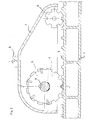
Bei dem erfindunqsgemäßen Verfahren wird mit einer mechanisch betriebenen Welle, auf der ein oder mehrere rotierende Schneidwerkzeuge sitzen, gearbeitet. Diese Welle ist beidseitig mittels eines zahnradartigen Stützrades oder gleitender Auflagerböcke auf dem Profilplateau abgestützt. Die örtliche Unterstützung hat die Aufgabe, beim Schneidvorgang den Unebenheiten der Oberfläche des Profiles bzw. des zusammengesetzten Plateaus zu folgen, um eine gleiche Einschnittiefe in die Längsrippen zu gewährleisten.In the method according to the invention, a mechanically operated shaft on which one or more rotating cutting tools are seated is used. This shaft is supported on both sides by means of a gear-like support wheel or sliding support blocks on the profile plateau. The local support has the task of following the unevenness of the surface of the profile or the assembled plateau during the cutting process in order to ensure an equal incision depth in the longitudinal ribs.
Zur Führung der Welle wird noch am Gehäuse eine zusätzliche Führungsrolle bzw. ein Gleitschuh angebracht. Die Vorschubbewegung der Vorrichtung wird vorzugsweise händisch oder auch mechanisch bewerkstelligt. Bei der mechanischen Bewegung läuft die Vorrichtung in einem Führungsrahmen, der Anpreßdruck auf das Plateau bzw. das Profil muß dabei über Federkraft oder Stoßdämpfer erfolgen, damit die Ungleichmäßigkeiten der Oberfläche ausgeglichen werden können.To guide the shaft, an additional guide roller or a sliding block is attached to the housing. The feed movement of the device is preferably accomplished manually or also mechanically. During the mechanical movement, the device runs in a guide frame, the contact pressure on the plateau or the profile must be by spring force or shock absorber so that the unevenness of the surface can be compensated.
Weitere Merkmale der Erfindung sind in Unteransprüchen beansprucht.Further features of the invention are claimed in the subclaims.
Die Erfindunq wird nachfolgend an einem Ausführungsbeispiel, das auch in der Zeichnung dargestellt ist, näher beschrieben. Es zeigen:
- Fig. 1 und Fig. 1a ein zu bearbeitendes Werkstück im Querschnitt und Draufsicht,
- Fig. 2 einen Schnitt durch eine erste Schneidvorrichtung,
- Fig. 3 einen gleichen Schnitt durch eine zweite Vorrichtung,
- Fig. 4 einen Querschnitt nach der Linie IV-IV der Fig. 3 und
- Fig. 5 einen Querschnitt nach der Linie V-V der Fig. 2.
- 1 and Fig. 1a a workpiece to be machined in cross section and top view,
- 2 shows a section through a first cutting device,
- 3 shows the same section through a second device,
- Fig. 4 shows a cross section along the line IV-IV of Fig. 3 and
- 5 shows a cross section along the line VV of FIG. 2nd
In Fig. 1 ist beispielsweise ein Profil 1 im Querschnitt und in Draufsicht dargestellt, wobei die Querschnittsdarstellung die Unebenheiten an der Oberfläche - stark übertrieben - erkennen läßt. Die Längsrippen 2 sind schon auf der einen Hälfte ausgeschnitten,um eine Querrillung 3 zu bilden. Auf der zweiten Flächenhälfte sind die Längsrippen 2 noch durchgehend.In Fig. 1, for example, a
Fig. 2 zeigt eine kcmplette Schneidvorrichtung als Variante mit zahnradartigen Stützrädern. Ein Stützrad 4, teilweise geschnitten dargestellt, wälzt sich auf der Grundfläche zwischen den Längsrippen 2 des Profiles 1 ab und hält so ein Fräserblatt 5 auf genaue Distanz zur Grundfläche des Profiles 1, weil der Durchmesser des Stützrades etwas größer ist als der des Fräserblattes 5. Beliebig viele Fräser sind auf einer Welle 6 aufgekeilt, während die äußeren Stützräder 4 lose auf der Welle 6 drehbar gelagert sind. Das Gehäuse 7 verbindet dieFig. 2 shows a kcm p lette cutting device as a variant with gear-like support wheels. A
Fräserwelle mit einem vorderen Stützrad 8 zum Zwecke der besseren Führung der Vorrichtung. Entweder händisch oder bei Verwendung eines starren Führungsrahmens mittels Federkraft wird die Vorrichtung bei 9 zum Andrücken auf das zu bearbeitende Profil belastet.Milling cutter shaft with a
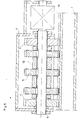
Eine weitere Schneidvorrichtung mit einem gleitenden Auflagerbock 10 als seitliche Abstützung ist in Fig. 3 gezeigt. Diese Auflagerböcke erfüllen denselben Zweck wie das Stützrad 4 in Fig 2, jedoch gleiten hier die beiden seitlichen Auflagerböcke 10 über die Oberkanten der Längsrippen 2 des Profiles 1. Der Durchmesser der Fräserblätter 5'ist in diesem Fall um die Tiefe der zu schneidenden Querriffelung größer als die Höhe der Auflagerböcke. Die vordere Führung wird bei dieser Variante beispielsweise durch einen Gleitschuh 11 bewerkstelligt.A further cutting device with a sliding Aufla erbock g of 10 as a lateral support shown in Fig. 3. These pedestals serve the same purpose as the supporting
Fig. 4 zeigt einen Querschnitt durch die Schneidvorrichtung nach Fig. 3 mit den gleitenden Auflagerböcken 10. Auf der Welle 6 sind eine beliebige Anzahl von Fräserscheiben 5 aufgekeilt, welche durch Distanzbüchsen 12 auf Abstand gehalten werden. Zur Abstützung sind außerhalb des Fräserpaketes die mit dem Gehäuse 7 verbundenen Auflagerböcke 10 vorgesehen, welche über die Oberfläche der Längsrippen 2 gleiten. Ein Antrieb 13 der Welle 6 erfolgt elektrisch oder anderweitig und ist am Gehäuse . befestigt.FIG. 4 shows a cross section through the cutting device according to FIG. 3 with the
In Fig. 5 ist die Schneidvorrichtung nach Fig. 2 im Querschnitt dargestellt. Die beiden außenseitig liegenden Stützräder 4 laufen lose auf der Welle 6 mit und halten die Distanz zur Oberfläche. Ansonsten ist die Ausführung wie in Fig. 4 beschrieben.5 shows the cutting device according to FIG. 2 in cross section. The two
Claims (5)
Applications Claiming Priority (2)
| Application Number | Priority Date | Filing Date | Title |
|---|---|---|---|
| AT4365/83 | 1983-12-15 | ||
| AT0436583A AT381265B (en) | 1983-12-15 | 1983-12-15 | METHOD AND DEVICE FOR PRODUCING CROSS-RIFLING ON LONG-RIBBED SURFACES |
Publications (3)
| Publication Number | Publication Date |
|---|---|
| EP0146110A2 true EP0146110A2 (en) | 1985-06-26 |
| EP0146110A3 EP0146110A3 (en) | 1987-08-05 |
| EP0146110B1 EP0146110B1 (en) | 1989-10-11 |
Family
ID=3563044
Family Applications (1)
| Application Number | Title | Priority Date | Filing Date |
|---|---|---|---|
| EP19840115202 Expired EP0146110B1 (en) | 1983-12-15 | 1984-12-12 | Device for manufacturing cross-grooves on length-wise grooved bottom plates, etc. |
Country Status (3)
| Country | Link |
|---|---|
| EP (1) | EP0146110B1 (en) |
| AT (1) | AT381265B (en) |
| DE (1) | DE3480061D1 (en) |
Cited By (2)
| Publication number | Priority date | Publication date | Assignee | Title |
|---|---|---|---|---|
| EP0709156A1 (en) * | 1994-10-28 | 1996-05-01 | Black & Decker Inc. | Jigsaw |
| US6626617B2 (en) * | 2000-02-02 | 2003-09-30 | Reich Spezialmaschinen Gmbh | Process for the milling of a groove into a board-like workpiece as well as processing machine for carrying out the process |
Citations (6)
| Publication number | Priority date | Publication date | Assignee | Title |
|---|---|---|---|---|
| CH315529A (en) * | 1953-10-28 | 1956-08-31 | Denes Zoltan | Method for cutting out stone blocks from the natural rock in a stone pit and system for carrying out this method |
| US3011530A (en) * | 1959-07-13 | 1961-12-05 | Lamb Ellard | Guide for portable saw |
| FR2256807A1 (en) * | 1974-01-07 | 1975-08-01 | Merzeau Jean Alain | Woodworking tool forming slots - has multiple sets of toothed rotary cutters and spacers altered to vary spacing of slots |
| DE2552484A1 (en) * | 1975-11-22 | 1977-05-26 | Helmut Meyer | MACHINE FOR THE MACHINING OF SURFACES |
| US4188934A (en) * | 1978-10-20 | 1980-02-19 | Cushion Cut, Inc. | Step safety groover apparatus |
| EP0082276A1 (en) * | 1981-11-19 | 1983-06-29 | Fritz Fleissner | Manually guided milling cutter for milling an inner shoulder on a gem setting |
-
1983
- 1983-12-15 AT AT0436583A patent/AT381265B/en not_active IP Right Cessation
-
1984
- 1984-12-12 EP EP19840115202 patent/EP0146110B1/en not_active Expired
- 1984-12-12 DE DE8484115202T patent/DE3480061D1/en not_active Expired
Patent Citations (6)
| Publication number | Priority date | Publication date | Assignee | Title |
|---|---|---|---|---|
| CH315529A (en) * | 1953-10-28 | 1956-08-31 | Denes Zoltan | Method for cutting out stone blocks from the natural rock in a stone pit and system for carrying out this method |
| US3011530A (en) * | 1959-07-13 | 1961-12-05 | Lamb Ellard | Guide for portable saw |
| FR2256807A1 (en) * | 1974-01-07 | 1975-08-01 | Merzeau Jean Alain | Woodworking tool forming slots - has multiple sets of toothed rotary cutters and spacers altered to vary spacing of slots |
| DE2552484A1 (en) * | 1975-11-22 | 1977-05-26 | Helmut Meyer | MACHINE FOR THE MACHINING OF SURFACES |
| US4188934A (en) * | 1978-10-20 | 1980-02-19 | Cushion Cut, Inc. | Step safety groover apparatus |
| EP0082276A1 (en) * | 1981-11-19 | 1983-06-29 | Fritz Fleissner | Manually guided milling cutter for milling an inner shoulder on a gem setting |
Cited By (2)
| Publication number | Priority date | Publication date | Assignee | Title |
|---|---|---|---|---|
| EP0709156A1 (en) * | 1994-10-28 | 1996-05-01 | Black & Decker Inc. | Jigsaw |
| US6626617B2 (en) * | 2000-02-02 | 2003-09-30 | Reich Spezialmaschinen Gmbh | Process for the milling of a groove into a board-like workpiece as well as processing machine for carrying out the process |
Also Published As
| Publication number | Publication date |
|---|---|
| AT381265B (en) | 1986-09-25 |
| EP0146110A3 (en) | 1987-08-05 |
| EP0146110B1 (en) | 1989-10-11 |
| ATA436583A (en) | 1986-02-15 |
| DE3480061D1 (en) | 1989-11-16 |
Similar Documents
| Publication | Publication Date | Title |
|---|---|---|
| DE3229601A1 (en) | INSULATION SHEET, ESPECIALLY MADE OF MINERAL FIBER FELT, WITH A GLUED LAMINATION, AND A METHOD FOR THEIR PRODUCTION AND METHOD FOR THEIR INSTALLATION | |
| DE3151835A1 (en) | RACK AND STEERING GEARBOX | |
| DE2525227B2 (en) | Device for grinding railroad tracks | |
| DE102005063327A1 (en) | Device for separating a plastic clay cord, with an effective notching device | |
| AT503550B1 (en) | EXTRUDED PROFILE, ESPECIALLY FLOOR PROFILE | |
| EP0185850A2 (en) | Underfloor wheelset lathe for reprofiling the contours of wheel rims of railway wheelsets | |
| DE3047565A1 (en) | Wooden pole for power lines or the like,and machine for producing same | |
| EP0146110A2 (en) | Device for manufacturing cross-grooves on length-wise grooved bottom plates, etc. | |
| DE3004965C2 (en) | ||
| DE2343471C2 (en) | Method and device for the production of long prestressed concrete elements | |
| DE2732620A1 (en) | PROCESS AND DEVICE FOR GRINDING, MILLING AND POLISHING WORKPIECES, LIKE GRANITE, MARBLE, BUILDING MATERIALS OR SIMILAR SPROEDE MATERIALS | |
| EP3684534A1 (en) | Under-floor wheel lathe machine having adjustable track width | |
| DE2727287C2 (en) | Device for bending profiled panels | |
| DE2748709A1 (en) | ROLLER STAND | |
| DE2636468A1 (en) | COPY MILLING MACHINE | |
| DE2918425C2 (en) | Method for height-compensating support of a track safety device while a structure is being pushed in under tracks and a device for carrying out the method | |
| DE926424C (en) | Method and device for the production of cutouts in metal strips or bands | |
| DE19624584C1 (en) | Cutting clay column with cutter wire | |
| DE3305666A1 (en) | Continuous calibrating machine for granite plates | |
| DE2543990B2 (en) | Horizontal splitting machine | |
| AT370321B (en) | DEVICE FOR PROCESSING SKIS WITH A RUNNING SURFACE | |
| DE2646483A1 (en) | PROFILING ROLLER | |
| DE1779692C (en) | Method and device for plastic sheathing of a particular profile made of wood or wood product | |
| DE2355241A1 (en) | Process and machinery for slitting strip metal - has one edge profiled direct from wider strip | |
| DE2460741C3 (en) | Device for aligning boards to be trimmed |
Legal Events
| Date | Code | Title | Description |
|---|---|---|---|
| PUAI | Public reference made under article 153(3) epc to a published international application that has entered the european phase |
Free format text: ORIGINAL CODE: 0009012 |
|
| AK | Designated contracting states |
Designated state(s): CH DE FR LI NL SE |
|
| RTI1 | Title (correction) | ||
| RAP1 | Party data changed (applicant data changed or rights of an application transferred) |
Owner name: AUSTRIA METALL AKTIENGESELLSCHAFT |
|
| PUAL | Search report despatched |
Free format text: ORIGINAL CODE: 0009013 |
|
| AK | Designated contracting states |
Kind code of ref document: A3 Designated state(s): CH DE FR LI NL SE |
|
| 17P | Request for examination filed |
Effective date: 19871211 |
|
| 17Q | First examination report despatched |
Effective date: 19880601 |
|
| GRAA | (expected) grant |
Free format text: ORIGINAL CODE: 0009210 |
|
| AK | Designated contracting states |
Kind code of ref document: B1 Designated state(s): CH DE FR LI NL SE |
|
| REF | Corresponds to: |
Ref document number: 3480061 Country of ref document: DE Date of ref document: 19891116 |
|
| ET | Fr: translation filed | ||
| PLBE | No opposition filed within time limit |
Free format text: ORIGINAL CODE: 0009261 |
|
| STAA | Information on the status of an ep patent application or granted ep patent |
Free format text: STATUS: NO OPPOSITION FILED WITHIN TIME LIMIT |
|
| 26N | No opposition filed | ||
| PGFP | Annual fee paid to national office [announced via postgrant information from national office to epo] |
Ref country code: SE Payment date: 19901221 Year of fee payment: 7 |
|
| PGFP | Annual fee paid to national office [announced via postgrant information from national office to epo] |
Ref country code: NL Payment date: 19901231 Year of fee payment: 7 Ref country code: FR Payment date: 19901231 Year of fee payment: 7 |
|
| PGFP | Annual fee paid to national office [announced via postgrant information from national office to epo] |
Ref country code: DE Payment date: 19910124 Year of fee payment: 7 |
|
| PGFP | Annual fee paid to national office [announced via postgrant information from national office to epo] |
Ref country code: CH Payment date: 19910227 Year of fee payment: 7 |
|
| PG25 | Lapsed in a contracting state [announced via postgrant information from national office to epo] |
Ref country code: SE Effective date: 19911213 |
|
| PG25 | Lapsed in a contracting state [announced via postgrant information from national office to epo] |
Ref country code: LI Effective date: 19911231 Ref country code: CH Effective date: 19911231 |
|
| PG25 | Lapsed in a contracting state [announced via postgrant information from national office to epo] |
Ref country code: NL Effective date: 19920701 |
|
| NLV4 | Nl: lapsed or anulled due to non-payment of the annual fee | ||
| PG25 | Lapsed in a contracting state [announced via postgrant information from national office to epo] |
Ref country code: FR Effective date: 19920831 |
|
| REG | Reference to a national code |
Ref country code: CH Ref legal event code: PL |
|
| PG25 | Lapsed in a contracting state [announced via postgrant information from national office to epo] |
Ref country code: DE Effective date: 19920901 |
|
| REG | Reference to a national code |
Ref country code: FR Ref legal event code: ST |
|
| EUG | Se: european patent has lapsed |
Ref document number: 84115202.8 Effective date: 19920704 |