EP0145832A2 - Method and apparatus for making a covered product - Google Patents
Method and apparatus for making a covered product Download PDFInfo
- Publication number
- EP0145832A2 EP0145832A2 EP84107646A EP84107646A EP0145832A2 EP 0145832 A2 EP0145832 A2 EP 0145832A2 EP 84107646 A EP84107646 A EP 84107646A EP 84107646 A EP84107646 A EP 84107646A EP 0145832 A2 EP0145832 A2 EP 0145832A2
- Authority
- EP
- European Patent Office
- Prior art keywords
- carrier
- blanks
- surface material
- connecting line
- laminated
- Prior art date
- Legal status (The legal status is an assumption and is not a legal conclusion. Google has not performed a legal analysis and makes no representation as to the accuracy of the status listed.)
- Granted
Links
- 238000000034 method Methods 0.000 title claims abstract description 24
- 239000000463 material Substances 0.000 claims abstract description 49
- 238000003475 lamination Methods 0.000 claims abstract description 9
- 238000004519 manufacturing process Methods 0.000 claims abstract description 7
- 238000007493 shaping process Methods 0.000 abstract description 4
- 238000005520 cutting process Methods 0.000 description 10
- 238000010030 laminating Methods 0.000 description 8
- 239000012876 carrier material Substances 0.000 description 4
- 238000000465 moulding Methods 0.000 description 3
- 238000012545 processing Methods 0.000 description 3
- 238000011161 development Methods 0.000 description 2
- 238000010438 heat treatment Methods 0.000 description 2
- 238000003466 welding Methods 0.000 description 2
- 239000004743 Polypropylene Substances 0.000 description 1
- 239000000853 adhesive Substances 0.000 description 1
- 238000004026 adhesive bonding Methods 0.000 description 1
- 230000001070 adhesive effect Effects 0.000 description 1
- 230000015572 biosynthetic process Effects 0.000 description 1
- 238000013461 design Methods 0.000 description 1
- 235000013312 flour Nutrition 0.000 description 1
- 230000003993 interaction Effects 0.000 description 1
- 210000001503 joint Anatomy 0.000 description 1
- -1 polypropylene Polymers 0.000 description 1
- 229920001155 polypropylene Polymers 0.000 description 1
- 238000009958 sewing Methods 0.000 description 1
- 230000003068 static effect Effects 0.000 description 1
- 238000012549 training Methods 0.000 description 1
- 238000012546 transfer Methods 0.000 description 1
- 239000002023 wood Substances 0.000 description 1
Images


Classifications
-
- B—PERFORMING OPERATIONS; TRANSPORTING
- B21—MECHANICAL METAL-WORKING WITHOUT ESSENTIALLY REMOVING MATERIAL; PUNCHING METAL
- B21D—WORKING OR PROCESSING OF SHEET METAL OR METAL TUBES, RODS OR PROFILES WITHOUT ESSENTIALLY REMOVING MATERIAL; PUNCHING METAL
- B21D53/00—Making other particular articles
- B21D53/88—Making other particular articles other parts for vehicles, e.g. cowlings, mudguards
-
- B—PERFORMING OPERATIONS; TRANSPORTING
- B29—WORKING OF PLASTICS; WORKING OF SUBSTANCES IN A PLASTIC STATE IN GENERAL
- B29C—SHAPING OR JOINING OF PLASTICS; SHAPING OF MATERIAL IN A PLASTIC STATE, NOT OTHERWISE PROVIDED FOR; AFTER-TREATMENT OF THE SHAPED PRODUCTS, e.g. REPAIRING
- B29C63/00—Lining or sheathing, i.e. applying preformed layers or sheathings of plastics; Apparatus therefor
- B29C63/0017—Lining or sheathing, i.e. applying preformed layers or sheathings of plastics; Apparatus therefor characterised by the choice of the material
- B29C63/0021—Lining or sheathing, i.e. applying preformed layers or sheathings of plastics; Apparatus therefor characterised by the choice of the material with coherent impregnated reinforcing layers
-
- B—PERFORMING OPERATIONS; TRANSPORTING
- B29—WORKING OF PLASTICS; WORKING OF SUBSTANCES IN A PLASTIC STATE IN GENERAL
- B29C—SHAPING OR JOINING OF PLASTICS; SHAPING OF MATERIAL IN A PLASTIC STATE, NOT OTHERWISE PROVIDED FOR; AFTER-TREATMENT OF THE SHAPED PRODUCTS, e.g. REPAIRING
- B29C51/00—Shaping by thermoforming, i.e. shaping sheets or sheet like preforms after heating, e.g. shaping sheets in matched moulds or by deep-drawing; Apparatus therefor
- B29C51/16—Lining or labelling
-
- B—PERFORMING OPERATIONS; TRANSPORTING
- B29—WORKING OF PLASTICS; WORKING OF SUBSTANCES IN A PLASTIC STATE IN GENERAL
- B29C—SHAPING OR JOINING OF PLASTICS; SHAPING OF MATERIAL IN A PLASTIC STATE, NOT OTHERWISE PROVIDED FOR; AFTER-TREATMENT OF THE SHAPED PRODUCTS, e.g. REPAIRING
- B29C51/00—Shaping by thermoforming, i.e. shaping sheets or sheet like preforms after heating, e.g. shaping sheets in matched moulds or by deep-drawing; Apparatus therefor
- B29C51/26—Component parts, details or accessories; Auxiliary operations
- B29C51/261—Handling means, e.g. transfer means, feeding means
- B29C51/262—Clamping means for the sheets, e.g. clamping frames
-
- B—PERFORMING OPERATIONS; TRANSPORTING
- B29—WORKING OF PLASTICS; WORKING OF SUBSTANCES IN A PLASTIC STATE IN GENERAL
- B29C—SHAPING OR JOINING OF PLASTICS; SHAPING OF MATERIAL IN A PLASTIC STATE, NOT OTHERWISE PROVIDED FOR; AFTER-TREATMENT OF THE SHAPED PRODUCTS, e.g. REPAIRING
- B29C63/00—Lining or sheathing, i.e. applying preformed layers or sheathings of plastics; Apparatus therefor
- B29C63/0004—Component parts, details or accessories; Auxiliary operations
-
- B—PERFORMING OPERATIONS; TRANSPORTING
- B29—WORKING OF PLASTICS; WORKING OF SUBSTANCES IN A PLASTIC STATE IN GENERAL
- B29C—SHAPING OR JOINING OF PLASTICS; SHAPING OF MATERIAL IN A PLASTIC STATE, NOT OTHERWISE PROVIDED FOR; AFTER-TREATMENT OF THE SHAPED PRODUCTS, e.g. REPAIRING
- B29C63/00—Lining or sheathing, i.e. applying preformed layers or sheathings of plastics; Apparatus therefor
- B29C63/02—Lining or sheathing, i.e. applying preformed layers or sheathings of plastics; Apparatus therefor using sheet or web-like material
- B29C63/04—Lining or sheathing, i.e. applying preformed layers or sheathings of plastics; Apparatus therefor using sheet or web-like material by folding, winding, bending or the like
-
- B—PERFORMING OPERATIONS; TRANSPORTING
- B60—VEHICLES IN GENERAL
- B60R—VEHICLES, VEHICLE FITTINGS, OR VEHICLE PARTS, NOT OTHERWISE PROVIDED FOR
- B60R13/00—Elements for body-finishing, identifying, or decorating; Arrangements or adaptations for advertising purposes
- B60R13/02—Internal Trim mouldings ; Internal Ledges; Wall liners for passenger compartments; Roof liners
- B60R13/0212—Roof or head liners
- B60R13/0225—Roof or head liners self supporting head liners
-
- B—PERFORMING OPERATIONS; TRANSPORTING
- B29—WORKING OF PLASTICS; WORKING OF SUBSTANCES IN A PLASTIC STATE IN GENERAL
- B29C—SHAPING OR JOINING OF PLASTICS; SHAPING OF MATERIAL IN A PLASTIC STATE, NOT OTHERWISE PROVIDED FOR; AFTER-TREATMENT OF THE SHAPED PRODUCTS, e.g. REPAIRING
- B29C51/00—Shaping by thermoforming, i.e. shaping sheets or sheet like preforms after heating, e.g. shaping sheets in matched moulds or by deep-drawing; Apparatus therefor
- B29C51/08—Deep drawing or matched-mould forming, i.e. using mechanical means only
- B29C51/082—Deep drawing or matched-mould forming, i.e. using mechanical means only by shaping between complementary mould parts
-
- B—PERFORMING OPERATIONS; TRANSPORTING
- B29—WORKING OF PLASTICS; WORKING OF SUBSTANCES IN A PLASTIC STATE IN GENERAL
- B29L—INDEXING SCHEME ASSOCIATED WITH SUBCLASS B29C, RELATING TO PARTICULAR ARTICLES
- B29L2031/00—Other particular articles
- B29L2031/30—Vehicles, e.g. ships or aircraft, or body parts thereof
- B29L2031/3005—Body finishings
- B29L2031/3011—Roof linings
-
- B—PERFORMING OPERATIONS; TRANSPORTING
- B29—WORKING OF PLASTICS; WORKING OF SUBSTANCES IN A PLASTIC STATE IN GENERAL
- B29L—INDEXING SCHEME ASSOCIATED WITH SUBCLASS B29C, RELATING TO PARTICULAR ARTICLES
- B29L2031/00—Other particular articles
- B29L2031/722—Decorative or ornamental articles
-
- Y—GENERAL TAGGING OF NEW TECHNOLOGICAL DEVELOPMENTS; GENERAL TAGGING OF CROSS-SECTIONAL TECHNOLOGIES SPANNING OVER SEVERAL SECTIONS OF THE IPC; TECHNICAL SUBJECTS COVERED BY FORMER USPC CROSS-REFERENCE ART COLLECTIONS [XRACs] AND DIGESTS
- Y10—TECHNICAL SUBJECTS COVERED BY FORMER USPC
- Y10T—TECHNICAL SUBJECTS COVERED BY FORMER US CLASSIFICATION
- Y10T156/00—Adhesive bonding and miscellaneous chemical manufacture
- Y10T156/10—Methods of surface bonding and/or assembly therefor
- Y10T156/1002—Methods of surface bonding and/or assembly therefor with permanent bending or reshaping or surface deformation of self sustaining lamina
- Y10T156/1028—Methods of surface bonding and/or assembly therefor with permanent bending or reshaping or surface deformation of self sustaining lamina by bending, drawing or stretch forming sheet to assume shape of configured lamina while in contact therewith
Definitions
- the invention relates to a method for producing a laminated molded part, in particular a motor vehicle interior trim part, which has a carrier which is heated for lamination without being deformed and is then introduced into a temperature-controlled deformation tool, where a surface material is assigned to it on the later visible surface is laminated onto the carrier during the deformation thereof.
- a method of the type just mentioned is known from practice.
- the carrier and the surface material are brought together in the forming tool and processed together.
- the tool can either be cold or tempered, depending on the requirements.
- the known method is advantageous in terms of costs, since it can be shaped, laminated and even trimmed in one operation.
- the carrier can only be laminated with a uniform surface material over its entire surface.
- the protruding surface material still has to be bent. Furthermore, in the case of the molded part laminated with two different surface materials, it is necessary to cover the connecting line between the different surface areas by a cover strip.
- the upper part of the laminating tool is lowered together with the clamping carrier until the upper and lower parts of the tool come to lie on one another and the hold-down device comes into contact with the surface of the carrier.
- the space above the surface material is vented so that the vacuum breaks down.
- the space below the surface material is evacuated through the carrier, whereby the surface material lies close to the carrier.
- the known method is again complicated because it requires a large number of process steps.
- the evacuation of the upper and lower part of the tool is expensive and requires special training of the tool.
- the known method can only be used for an air-permeable material for the carrier, since otherwise the surface material cannot be used on the carrier during the actual lamination.
- the present invention has for its object to provide a method of the type mentioned, with which a molded part can be laminated to at least two areas with different surface materials in a simple and cost-saving manner.
- the surface material in the form of at least two blanks covering different areas of the carrier is kept tensioned in the shaping tool and the carrier is clamped to the tensioned by means of gripper elements which clamp from above and below along at least one overlap or joint or connecting line Blanks is pressed before the carrier is deformed together with the blanks.
- the method according to the invention shows only a few deformation steps, is cost-saving and nevertheless offers the possibility of having the molded part on different surface areas. to hide separate surface material.
- the molded part is shaped and laminated in one operation. At the same time, it is still possible to trim it in this single operation.
- the lamination with different surface material is achieved in a surprising manner, although the tool evacuation devices known from the prior art are completely dispensed with. It is particularly advantageous that the invention is not restricted to an air-permeable carrier material or air-impermeable surface material. The choice of possible materials is therefore much larger in the invention.
- the gripper elements are an effective device to fix the surface cuts along the connecting line on the carrier and thus to ensure their mutual association in the subsequent subsequent deformation.
- the carrier is brought up to the blanks stretched in one plane in order to first fix it to the blanks along the connecting line. It is important that the carrier is still undeformed and is only subsequently deformed when the upper and lower punches of the shaping tool are moved relatively towards one another. This means that the carrier is only formed after the position of the connecting line of the blanks on it has been determined. The carrier is thus shaped as a function of the connecting line of the blanks. The result of this is that the connecting line of the blanks is always exactly aligned with the carrier and it cannot happen, as in the non-generic methods of the prior art, that the connecting line comes to lie laterally offset in the preformed carrier.
- connecting line Due to the exact formation of the connecting line, it is also possible with the invention to dispense with a cover strip despite the use of different surface materials for the lamination.
- the carrier is connected to the blanks along the overlap, butt or connecting line before it is deformed.
- the blanks are not only fixed on the carrier, but also ensure a first connection between these parts.
- blanks are tensioned and fed to the deformation tool as web material.
- the term "blanks" is to be interpreted broadly. It addresses any material that can be used for surface lamination, regardless of whether it is real blanks with a defined area or web material with an endless area. Used if the said web material, it is at least to be ensured that the material determining the overlap, butt or connecting line has a clean cutting edge along this line.
- the supply as web material in a tensioned state enables fabrication from the roll and lowers the manufacturing costs.
- the invention also provides a device for producing molded parts of the type mentioned in the introduction.
- This device is characterized in that a gripper element for the surface material formed from at least two blanks is arranged opposite each other in the upper and lower punches, which in the gripping position (see FIG. 1) is arranged in an outstanding manner relative to the corresponding punch and in the latter against the force of a resistance element are retractable.
- the gripper elements which protrude before the deformation process serve to fix the tensioned surface material on the carrier before it is deformed together with the blanks.
- the gripper elements can move back into the respective punch against a resistance force, for example against the force of a spring, in order to enable the deformation movement.
- the resistance can be selected so that the necessary contact pressure is available for this subarea when the blanks are fixed on the carrier.
- it can also be controlled so that the necessary connection pressure is only applied at the actual time of the deformation, for example by limiting the lowering movement of the gripper elements. An interim solution is also conceivable.
- the uppermost is provided with a tensioning device for tensioning the surface blanks in one plane, up to which the gripper element associated with this punch protrudes as far as possible in its gripping position.
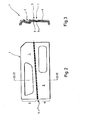
- the devices shown are used in each case for producing a laminated molded part 1, in particular a motor vehicle interior trim part, as shown in FIGS. 2 to 5.
- the molding each has a carrier 2, which in the present case consists of polypropylene filled with wood flour. It is laminated with surface material 3 on the later visible surface.
- the available surface is divided into at least two areas which are separated from one another by an overlapping or abutting or connecting line 4.
- the blank 8 overlaps the blank 7.
- a recess 9 of cross section U-shaped in the carrier is provided exactly in the course of the connecting line 4.
- the first blank is shown in dash-dotted lines in FIG. 3, while the second blank 8 is cut with a dashed line.
- the molded part 1 three or. taking into account the additional connecting elements, if desired, even four different areas, each covered with different surface materials. These areas are also separated from each other by connecting lines. The differences in the structure of the surface material are indicated by different markings.
- the other two connecting lines 4 and 10 branch off from the horizontal straight connecting line at an angle of approximately 60 °.
- the molded part 1 has two different areas, analogous to the embodiment of FIG. 2, but are separated from one another by a partially curved connecting line 4.
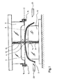
- FIG. 1 shows a cross section through a device according to the invention for producing a laminated molded part 1.
- the device has a vertically movable upper punch 11, to which a stationary lower punch 12 is assigned.
- the upper stamp has a recess in its shape which is adapted to the shape of the lower stamp.
- both the upper and the lower punches have strip-shaped gripper elements 13 and 14, which are arranged sunk in the punches against the force of springs.
- the gripper elements with their mutually assigned gripping surfaces determine the surface shape of the connecting line.
- a clamping frame 16 is fastened to the upper punch 11 with the aid of known fastening means, such as screws 15, which serves to keep the blanks 7, 8 tensioned within the device shown.
- the tenter frame has a larger base area than the molded part 1 and in the present case surrounds the upper punch 11 from all four sides. It is important that the blanks are stretched in the direction of the connecting line 4 in order to achieve an exact alignment of the blanks in this area. In addition, they can also be stretched transversely to the connecting line 4, if it is ensured that the exact line course is not disturbed by the connecting line.
- the two blanks 7 and 8 are practically stretched in a plane E and in the present case overlap to a depth of approximately 5 mm.
- the clamping plane E rests on the underside of the upper punch 11.
- the strip-shaped gripper element 14 of the lower punch 12 is arranged in the opposite direction to the gripper element 13, so that the respective gripping surfaces can bring about a firm clamping grip, the strength of which can be adjusted by dimensioning the corresponding springs.
- the gripping position shown in FIG. 1 it is possible either to use the clamping handle only for fixing the carrier to the blanks, or to physically connect these parts to one another in this position, for example by means of HF welding. If in the gripping position of Figure 1, the gripper elements 13 and 14 the Only fix parts, so the springs are dimensioned so that the physical connection takes place at the latest during the deformation stroke.
- the gripper element 13 protrudes so far in the gripping position of Figure 1 that the actual gripping surface is near or in the plane of the underside of the upper punch. This lies directly parallel to the clamping plane E of the clamping frame 16.
- the gripper element 14 protrudes from the surface of the lower punch 12 by approximately the same amount a as is the case with the gripper element 13.
- the device of Figure 1 is shown in plan view at the workplace. It should be noted that the device is designed as a 4-column press, the columns 17 being arranged in each case in the corner points of the rectangular plan.
- a feed belt 18 for the blank of the carrier 2 can be seen on the lower, longer rectangular side of the illustration.
- the arrow R indicates the conveying direction leading to the press.
- the carrier material passes through a heating station 19 in front of the press, in which the initially cold carrier is heated. From there, the carrier is fed to the deformation tool.
- clamping frame 6 which in the present case has two blanks 7 and 8 analogous to the molded part embodiment in FIG.
- two or more are first placed in the clamping frame 16 Blanks clamped in the desired arrangement.
- the frame is then attached to the upper punch 11 in a ready position, in which the upper punch 11 is raised relatively far from the lower punch 12, so that the blanks stretched in the clamping plane E are on the underside of the upper punch 11 or close to the gripping surface of the gripper element 13 come to rest.
- the position of the stenter frame can be arranged differently within plane E, just as its gripping force can be adjusted differently.
- a carrier which has already been heated up in the heating station 19 is moved into the molding tool which is still in the ready position and is placed on the lower punch 12.
- the molding tool can be cold or tempered as desired.
- the gripper element 14 may already be in the extended position shown in FIG. 1 for the placement of the carrier, or it may also be recessed. In the second case, it must later be extended upwards by the height a, namely when the upper and lower punches 11 and 12 move towards one another in the gripper position shown in FIG.
- the carrier is first brought up to the blanks 7 and 8 only in the region of the connecting line 4 and either only on these laid, or even now physically connected to them by lamination.
- the mutually assigned gripping surfaces of the gripper elements 13 and 14 can be provided with a pattern in order to impress this pattern on the connecting line or, if necessary, to increase the static friction.
- the deformation stroke takes place, in which case the upper punch lowers downwards together with the clamping frame.
- the gripper elements 13 and 14 move back in their guides as the deformation stroke progresses, so that they protrude less and less from the adjacent punch surface.
- the upper punch 11 lowers on the lower punch 12 until it reaches its end position, in which the carrier takes on the final shape together with the blanks and the blanks are laminated onto the carrier due to the deformation pressure. Since the carrier is already fixed in the area of the connecting line 4 with the blanks before the deformation begins, it is ensured that the shape of the connecting line predetermined by the gripper elements 13 and 14 is also exactly maintained.
- the carrier is only formed after the blanks are fixed to one another and to the carrier, the connecting line also comes to lie exactly at the base of the groove 9.
- the gripper element 14 can serve as an ejector.
- FIG. 4 shows a carrier which is not only topped with two, but with three or four blanks. For this production, it is provided to connect the blanks together before lamination, for example by sewing, welding, gluing or the like. The blanks can then be introduced and processed in a stenter frame in the usual manner, as described above.
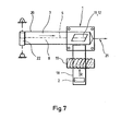
- FIG. 7 shows a 4-column press in plan view, as is already known from FIG. 6.
- the feed for the carrier material is also unchanged, which is why it will not be discussed further here.
- the feed for the blanks 7 and 8 which takes place from the roll in the present case.
- the blanks are along the common, parallel to the longitudinal extent of the rolled-up cutting band 20 sewn together or already taken into account accordingly in the manufacture of the surface material.
- the roll is detachably mounted so that the cutting band 20, in the present case at right angles to the feed direction R, is fed into the column press.
- a schematically illustrated tensioning device 21 holds the cutting tape 20 in tension in the direction of the longitudinal extent of the tape.
- the roller 22 is braked in the bearings to allow tension.
- the blanking belt 20 enables the blanks to be fed uninterrupted, step by step. In order to maintain the tension during processing, it is either provided to make the cutting band wider than is actually necessary for laminating the molded part 1. In this way, edge strips remain, which in turn can be wound up and transfer the tensile force to the unprocessed cutting tape. If, on the other hand, the cutting tape should only be made as wide as is necessary for laminating the molded part, the tensioning device 21 must be set up so that it is newly linked to the part of the cutting tape 20 that is to be processed after each laminating process.
- separating elements 23 can be provided in order to separate protruding parts of the blanks and / or the carrier after the deformation stroke and, if necessary, at the same time to bend the resulting body edge.
- the device 1 of FIG. 8 is constructed similarly to that of FIG. 7, which is why only the differences will be discussed.
- the same parts are provided with the same reference numerals.
- the blanks 7 and 8 can either already be overlapping on the roller 22 or the overlap is achieved by guide elements which are arranged between the roller 22 and the device 1.
- the gripper elements can be designed, for example, as high-frequency electrodes.
- FIG. 9 corresponds essentially to that of FIG. 1.
- the same parts are provided with the same, identical reference numerals. Only the different features are discussed below.
- the gripper elements 13, 14 each have self-advancing strips 25 and 26 in the strip direction, which functionally correspond to the gripper elements 13 and 14. They are each resiliently mounted in the gripper elements so that in the ready position of the tool shown in FIG. 9 they protrude beyond the surface of the gripper elements assigned to the workpiece in the direction of the center of the tool. These additional strips serve to achieve an early and precise fixation in the case of material separating lines provided in strongly deformed workpiece areas.
- the strips 25, 26 usually extend over the length of the gripper elements 13, 14. However, they can also be shorter.
- the gripper elements 13, 14 and the strips 25, 26 are arranged so that they can be delivered by means of springs.
- actuating devices can also be used, with the aid of which the gripper elements and strips can be actuated in the delivery direction if desired.
Abstract
Die Erfindung bezieht sich auf ein Verfahren zum Herstellen eines kaschierten Formteils, insbesondere eines Kfz-Innenraumverkleidungsteiles, das einen Träger aufweist, der zum Kaschieren unverformt erhitzt und dann in ein temperiertes Verformungswerkzeug eingeführt wird, wo ihm an der späteren Sichtoberfläche ein Oberflächenmaterial zugeordnet wird, das während des Verformens des Trägers auf diesen aufkaschiert wird. Der vorliegenden Erfindung liegt die Aufgabe zugrunde, ein Verfahren der eingangs genannten Art zu schaffen, mit dem auf einfache und kostensparende Art und Weise ein Formteil auf wenigstens zwei Bereichen mit unterschiedlichen Qberflächenmaterialien kaschiert werden kann. Diese Aufgabe wird erfindungsgemäß dadurch gelöst, daß das Oberflächenmaterial in Form wenigstens zweier, unterschiedlicher Bereiche des Trägers abdeckender Zuschnitte, im Verformungswerkzeug gespannt gehalten und der Träger mittels von oben und unten klemmender Greiferelemente entlang wenigstens einer Überlappungs- oder Stoß- bzw. Verbindungslinie an die gespannten Zuschnitte angedrückt wird, ehe der Träger zusammen mit den Zuschnitten verformt wird.The invention relates to a method for producing a laminated molded part, in particular a motor vehicle interior trim part, which has a carrier which is heated for lamination without being deformed and is then introduced into a temperature-controlled deformation tool, where a surface material is assigned to it on the later visible surface is laminated onto the carrier during the deformation thereof. The present invention has for its object to provide a method of the type mentioned, with which a molded part can be laminated in at least two areas with different surface materials in a simple and cost-saving manner. This object is achieved according to the invention in that the surface material in the form of at least two blanks covering different regions of the carrier is held taut in the shaping tool and the carrier is clamped to the clamped along at least one overlap or joint or connecting line by means of gripper elements which clamp from above and below Blanks is pressed before the carrier is deformed together with the blanks.
Description
Die Erfindung bezieht sich auf ein Verfahren zum Herstellen eines kaschierten Formteils, insbesondere eines Kfz-Innenraumverkleidungsteiles, das einen Träger aufweist, der zum Kaschieren unverformt erhitzt und dann in ein temperiertes Verformungswerkzeug eingeführt wird, wo ihm an der späteren Sichtoberfläche ein Oberflächenmaterial zugeordnet wird, das während des Verformens des Trägers auf diesen aufkaschiert wird.The invention relates to a method for producing a laminated molded part, in particular a motor vehicle interior trim part, which has a carrier which is heated for lamination without being deformed and is then introduced into a temperature-controlled deformation tool, where a surface material is assigned to it on the later visible surface is laminated onto the carrier during the deformation thereof.
Ein Verfahren der eben genannten Art ist aus der Praxis bekannt. Der Träger und das Oberflächenmaterial werden im Verformungswerkzeug zusammengeführt und miteinander verarbeitet. Hierzu kann das Werkzeug je nach Anforderung entweder kalt oder temperiert sein.A method of the type just mentioned is known from practice. The carrier and the surface material are brought together in the forming tool and processed together. For this purpose, the tool can either be cold or tempered, depending on the requirements.
Das bekannte Verfahren ist von den Kosten her vorteilhaft, da in einem Arbeitsgang geformt, kaschiert und sogar beschnitten werden kann.The known method is advantageous in terms of costs, since it can be shaped, laminated and even trimmed in one operation.
Nachteilig ist dagegen, daß der Träger nur auf seiner gesamten Oberfläche mit einem einheitlichen Oberflächenmaterial kaschiert werden kann.On the other hand, it is disadvantageous that the carrier can only be laminated with a uniform surface material over its entire surface.
Aus der Praxis ist ein anderes, gattungsfremdes Verfahren bekannt, bei dem kaltes Trägermaterial in einem beheizten Verformungswerkzeug geformt und beschnitten wird. Der auf diese Art und Weise vorgeformte Träger wird anschließend mit Kleber eingespritzt und in einem Folgewerkzeug mit Oberflächenmaterial kaschiert. Dabei besteht die Möglichkeit, den Träger in zwei aufeinanderfolgenden Verfahrensschritten mit zwei unterschiedlichen Materialien zu kaschieren, die verschiedene Bereiche der Oberfläche abdecken.Another, non-generic method is known from practice, in which cold carrier material is shaped and trimmed in a heated shaping tool. The carrier preformed in this way is then injected with adhesive and laminated with surface material in a subsequent tool. There is the possibility of the carrier in two successive process steps with two un different materials that cover different areas of the surface.
Bei dem auf diese Art und Weise kaschierten Formteil muß noch das überstehende Oberflächenmaterial umgebugt werden. Weiterhin ist es bei dem mit zwei unterschiedlichen Oberflächenmaterialien kaschierten Formteil notwendig, die Verbindungslinie zwischen den verschiedenen Oberflächenbereichen durch eine Deckleiste abzudecken.With the molded part laminated in this way, the protruding surface material still has to be bent. Furthermore, in the case of the molded part laminated with two different surface materials, it is necessary to cover the connecting line between the different surface areas by a cover strip.
Das bekannte Verfahren ist nachteilig, da es vielfältige Verfahrensschritte bedingt, die aus Kostengründen vermieden werden sollen. Aus der DE-OS 31 09 338 ist ein ähnlich gattungsfremdes Verfahren bekannt, bei dem zwei Zuschnitte unterschiedlichen Oberflächenmaterials gleichzeitig und nicht wie bisher beschrieben nacheinander auf einen vorgeformten Träger aufgebracht werden. Die Zuschnitte werden hierzu in einem Spannrahmen dem separaten Kaschierwerkzeug zugeführt. Entlang der Verbindungslinie der beiden Zuschnitte wird ein Niederhalter angeordnet, der die Zuschnitte hält . Die Zuschnitte werden anschließend erhitzt und durch Evakuierung des Oberteiles des Kaschierwerkzeuges nach oben gesaugt.The known method is disadvantageous because it requires a variety of process steps that should be avoided for reasons of cost. From DE-OS 31 09 338 a similar method of a different kind is known, in which two blanks of different surface material are applied simultaneously to one another and not as previously described on a preformed carrier. The blanks are fed to the separate laminating tool in a clamping frame. A hold-down is arranged along the connecting line of the two blanks, which holds the blanks. The blanks are then heated and sucked upwards by evacuating the upper part of the laminating tool.
Zum Kaschieren des in der Unterform des Kaschierwerkzeuges bereitgestellten, vorverformten Trägers wird das Oberteil des Kaschierwerkzeuges zusammen mit dem Spannträger so weit abgesenkt, bis das Ober- und Unterteil des Werkzeuges aufeinander zu liegen kommen und der Niederhalter in Berühung gerät mit der Oberfläche des Trägers.To laminate the pre-formed carrier provided in the lower mold of the laminating tool, the upper part of the laminating tool is lowered together with the clamping carrier until the upper and lower parts of the tool come to lie on one another and the hold-down device comes into contact with the surface of the carrier.
Um das Oberflächenmaterial in Anlage mit dem Träger zu bringen, wird der Raum oberhalb des Oberflächenmaterials gelüftet, so daß das Vakuum zusammenbricht. Dafür wird der Raum unterhalb des Oberflächenmaterials durch den Träger hindurch evakuiert, wodurch sich das Oberflächenmaterial dicht an den Träger anlegt.In order to bring the surface material into contact with the carrier, the space above the surface material is vented so that the vacuum breaks down. For this purpose, the space below the surface material is evacuated through the carrier, whereby the surface material lies close to the carrier.
Das bekannte Verfahren ist wiederum kompliziert aufgebaut, weil es eine Vielzahl von Verfahrensschritten erforderlich macht. Insbesondere das Evakuieren des Ober-und Unterteiles des Werkzeuges ist kostspielig und erfordert eine spezielle Ausbildung des Werkzeuges. Darüber hinaus ist das bekannte Verfahren nur anwendbar bei einem luftdurchlässigen Werkstoff für den Träger, da ansonsten das Oberflächenmaterial beim eigentlichen Kaschieren nicht an den Träger herangezogen werden kann. Weiterhin ist es unabdingbar, daß das Oberflächenmaterial selbst luftundurchlässig ist, da anders die Wechselwirkung des gegenseitigen Evakuieren des Ober- und Unterteils des Kaschierwerkzeuges wirkungslos wäre.The known method is again complicated because it requires a large number of process steps. In particular, the evacuation of the upper and lower part of the tool is expensive and requires special training of the tool. In addition, the known method can only be used for an air-permeable material for the carrier, since otherwise the surface material cannot be used on the carrier during the actual lamination. Furthermore, it is essential that the surface material itself is impermeable to air, since otherwise the interaction of the mutual evacuation of the upper and lower part of the laminating tool would be ineffective.
Der vorliegenden Erfindung liegt die Aufgabe zugrunde, ein Verfahren der eingangs genannten Art zu schaffen, mit dem auf einfache und kostensparende Art und Weise ein Formteil auf wenigstens zwei Bereichen mit unterschiedlichen Oberflächmaterialien kaschiert werden kann.The present invention has for its object to provide a method of the type mentioned, with which a molded part can be laminated to at least two areas with different surface materials in a simple and cost-saving manner.
Diese Aufgabe wird erfindungsgemäß dadurch gelöst, daß das Oberflächenmaterial in Form wenigstens zweier, unterschiedlicher Bereiche des Trägers abdeckender Zuschnitte, im Verformungswerkzeug gespannt gehalten und der Träger mittels von oben und unten klemmender Greiferelemente entlang wenigstens einer Überlappungs- oder Stoß- bzw. Verbindungslinie an die gespannten Zuschnitte angedrückt wird, ehe der Träger zusammen mit den Zuschnitten verformt wird.This object is achieved according to the invention in that the surface material in the form of at least two blanks covering different areas of the carrier is kept tensioned in the shaping tool and the carrier is clamped to the tensioned by means of gripper elements which clamp from above and below along at least one overlap or joint or connecting line Blanks is pressed before the carrier is deformed together with the blanks.
Das erfindungsgemäße Verfahren zeigt nur wenige Verformungsschritte, ist kostensparend und bietet dennoch die Möglichkeit, das Formteil an verschiedenen Oberflächenbereichen mit. gesondertem Oberflächenmaterial zu kaschieren.The method according to the invention shows only a few deformation steps, is cost-saving and nevertheless offers the possibility of having the molded part on different surface areas. to hide separate surface material.
Zunächst ist zu bemerken, daß auch beim erfindungsgemäßen Verfahren in einem Arbeitsgang das Formteil geformt und kaschiert wird. Gleichzeitig ist es noch möglich, es bei diesem einzigen Arbeitsgang auch zu beschneiden.First of all, it should be noted that even in the method according to the invention, the molded part is shaped and laminated in one operation. At the same time, it is still possible to trim it in this single operation.
Das Kaschieren mit unterschiedlichem Oberflächenmaterial wird auf überraschende Art und Weise erreicht, obwohl man auf die aus dem Stand der Technik bekannten Evakuierungseinrichtungen beim Werkzeug gänzlich verzichtet. Besonders vorteilhaft ist die Tatsache, daß man bei der Erfindung auf kein luftdurchlässiges Trägermaterial bzw. luftundurchlässiges Oberflächenmaterial festgelegt ist. Die Auswahl der möglichen Werkstoffe ist deshalb bei der Erfindung sehr viel größer.The lamination with different surface material is achieved in a surprising manner, although the tool evacuation devices known from the prior art are completely dispensed with. It is particularly advantageous that the invention is not restricted to an air-permeable carrier material or air-impermeable surface material. The choice of possible materials is therefore much larger in the invention.
Die Greiferelemente sind eine wirksame Einrichtung, um die Oberflächenzuschnitte entlang der Verbindungslinie auf dem Träger festzulegen und damit bei der anschliessenden folgenden Verformung in der gegenseitigen Zuordnung zu sichern. Bei der Erfindung wird im Gegensatz zum Stand der Technik der Träger an die in einer Ebene gespannten Zuschnitte herangeführt, um ihn zunächst entlang der Verbindungslinie an den Zuschnitten festzulegen. Dabei ist wichtig, daß der Träger noch unverformt ist und erst anschließend verformt wird, wenn der Ober-und Unterstempel des Verformungswerkzeuges relativ aufeinander zubewegt werden. Dies bedeutet, daß der Träger erst geformt wird, nachdem die Position der Verbindungslinie der Zuschnitte auf ihm bestimmt ist. Der Träger wird also gleichsam in Abhängigkeit von der Verbindungslinie der Zuschnitte geformt. Die Folge davon ist, daß die Verbindungslinie der Zuschnitte immer exakt am Träger ausgerichtet ist und es nicht wie bei den gattungsfremden Verfahren des Standes der Technik passieren kann, daß die Verbindungslinie beim vorgeformten Träger seitlich versetzt zu liegen kommt.The gripper elements are an effective device to fix the surface cuts along the connecting line on the carrier and thus to ensure their mutual association in the subsequent subsequent deformation. In contrast to the prior art, in the case of the invention, the carrier is brought up to the blanks stretched in one plane in order to first fix it to the blanks along the connecting line. It is important that the carrier is still undeformed and is only subsequently deformed when the upper and lower punches of the shaping tool are moved relatively towards one another. This means that the carrier is only formed after the position of the connecting line of the blanks on it has been determined. The carrier is thus shaped as a function of the connecting line of the blanks. The result of this is that the connecting line of the blanks is always exactly aligned with the carrier and it cannot happen, as in the non-generic methods of the prior art, that the connecting line comes to lie laterally offset in the preformed carrier.
Bedingt durch die exakte Ausbildung der Verbindungslinie ist es bei der Erfindung auch möglich,trotz Verwendung unterschiedlichen Oberflächenmaterials für die Kaschierung auf eine Deckleiste zu verzichten.Due to the exact formation of the connecting line, it is also possible with the invention to dispense with a cover strip despite the use of different surface materials for the lamination.
Bei einer vorteilhaften Weiterbildung der Erfindung ist vorgesehen, daß der Träger mit den Zuschnitten entlang der Überlappungs-, Stoß- bzw. Verbindungslinie verbunden wird, ehe er verformt wird. Bei diesem Verfahrensschritt legt man die Zuschnitte nicht nur am Träger fest, sondern sorgt auch für eine erste Verbindung zwischen diesen Teilen.In an advantageous development of the invention it is provided that the carrier is connected to the blanks along the overlap, butt or connecting line before it is deformed. In this process step, the blanks are not only fixed on the carrier, but also ensure a first connection between these parts.
Eine andere vorteilhafte Weiterbildung der Erfindung besteht darin, daß die Zuschnitte als Bahnmaterial gespannt dem Verformungswerkzeug zugeführt werden. Der Begriff "Zuschnitte" ist weit auszulegen. Es wird damit jegliches für eine Oberflächenkaschierung verwendbare Material angesprochen, gleichgültig, ob es sich dabei um echte Zuschnitte mit definierter Fläche oder um Bahnmaterial mit endloser Fläche handelt. Benutzt man das besagte Bahnmaterial, so ist zumindest darauf zu achten, daß das die Überlappungs-,Stoß- oder Verbindungslinie bestimmende Material längs dieser Linie eine saubere Schnittkante aufweist.Another advantageous further development of the invention consists in that the blanks are tensioned and fed to the deformation tool as web material. The term "blanks" is to be interpreted broadly. It addresses any material that can be used for surface lamination, regardless of whether it is real blanks with a defined area or web material with an endless area. Used if the said web material, it is at least to be ensured that the material determining the overlap, butt or connecting line has a clean cutting edge along this line.
Die Zuführung als Bahnmaterial in gespanntem Zustand ermöglicht die Fabrikation von der Rolle und senkt die Herstellungskosten.The supply as web material in a tensioned state enables fabrication from the roll and lowers the manufacturing costs.
Die Erfindung stellt auch eine Vorrichtung zur Verfügung, um Formteile der eingangs genannten Art herzustellen. Diese Vorrichtung ist dadurch gekennzeichnet, daß im Ober- und Unterstempel einander entgegengerichtet je ein Greiferelement für das aus wenigstens zwei Zuschnitten gebildete Oberflächenmaterial angeordnet ist, die in Greifposition (siehe Figur 1) gegenüber dem entsprechenden Stempel herausragend angeordnet und in diesen gegen die Kraft eines Widerstandselementes versenkbar gelagert sind.The invention also provides a device for producing molded parts of the type mentioned in the introduction. This device is characterized in that a gripper element for the surface material formed from at least two blanks is arranged opposite each other in the upper and lower punches, which in the gripping position (see FIG. 1) is arranged in an outstanding manner relative to the corresponding punch and in the latter against the force of a resistance element are retractable.
Die vor dem Verformungsvorgang herausragenden Greiferelemente dienen dazu, daß gespannte Oberflächenmaterial auf dem Träger festzulegen, ehe dieser zusammen mit den Zuschnitten verformt wird. Beim Verformen können die Greiferelemente gegen eine Widerstandskraft, beispielsweise gegen die Kraft einer Feder, in den jeweiligen Stempel zurückfahren, um die Verformungsbewegung zu ermöglichen. Die Widerstandskraft kann so gewählt werden, daß bereits beim Festlegen der Zuschnitte auf dem Träger für diesen Teilbereich die notwendige Anpresskraft zur Verfügung steht. Sie kann aber auch so gesteuert werden, daß erst zum eigentlichen Verformungszeitpunkt, beispielsweise durch eine Begrenzung der Versenkbewegung der Greiferelemente der notwendige Verbindungsdruck aufgebracht wird. Aucn eine Zwischenlösung ist denkbar.The gripper elements which protrude before the deformation process serve to fix the tensioned surface material on the carrier before it is deformed together with the blanks. When deforming, the gripper elements can move back into the respective punch against a resistance force, for example against the force of a spring, in order to enable the deformation movement. The resistance can be selected so that the necessary contact pressure is available for this subarea when the blanks are fixed on the carrier. However, it can also be controlled so that the necessary connection pressure is only applied at the actual time of the deformation, for example by limiting the lowering movement of the gripper elements. An interim solution is also conceivable.
Im Hinblick auf eine einfache Ausbildung des Verformungswerkzeuges ist es vorteilhaft, wenn der Oberstemmit einer Spanneinrichtung zum Spannen der Oberflächenzuschnitte in einer Ebene versehen ist, bis zu welcher das diesem Stempel zugeordnete Greiferelement in seiner Greifposition maximal herausragt.With regard to a simple design of the deformation tool, it is advantageous if the uppermost is provided with a tensioning device for tensioning the surface blanks in one plane, up to which the gripper element associated with this punch protrudes as far as possible in its gripping position.
Ausführungsbeispiele der Erfindung sind nachfolgend anhand einer Zeichnung beschrieben.Embodiments of the invention are described below with reference to a drawing.
Es zeigir:
Figur 1 eine Schnittansicht durch eine Vorrichtung zum Herstellen eines kaschierten Formteils mit geöffneten Ober- und Unterstempel,Figur 2 eine Draufsicht auf ein Formteil, das an der Oberfläche mit zwei separaten Oberflächenmaterialien kaschiert ist,Figur 3 der Schnitt durch das Formteil von Fig. 2 gemäß Linie III-III,- Figuren Draufsicht auf weitere Formteile, die an ih-4 und 5 rer Oberfläche mehr als zwei unterschiedliche Zuschnitte aufweisen bzw. bei denen die Trennungslinie zwischen den Zuschnitten nicht ausschließlich in einer Geraden verläuft,
Figur 6 eine schematische Draufsicht auf die Vorrichtung vonFigur 1,Figur 7 eine schematische Draufsicht auf eine zweite Ausführungsform der erfindungsgemäßen Vorrichtung, bei der das Oberflächenmaterial aus zwei längs der gemeinsamen Verbindungslinie miteinander verbundenen Zuschnittsbahnen besteht,Figur 8 eine schematische Draufsicht auf eine weitere Ausführungsform der erfindungsgemäßen Vorrichtung, die als Oberflächenmaterial zwei separate Zuschnittbahnen verarbeitet und- Figur 9 eine schematische Schnittansicht einer weiteren Ausführungsform, bei der die Greiferelemente jeweils durch voreilende Leisten ergänzt. sind.
- FIG. 1 shows a sectional view through a device for producing a laminated molded part with open upper and lower punches,
- FIG. 2 shows a plan view of a molded part that is laminated on the surface with two separate surface materials,
- 3 shows the section through the molded part of FIG. 2 according to line III-III,
- Figures top view of further molded parts which have more than two different blanks on their surface and where the dividing line between the blanks does not run exclusively in a straight line,
- FIG. 6 shows a schematic top view of the device from FIG. 1,
- Figure 7 is a schematic plan view of a second embodiment of the device according to the invention, in which the surface material from two there are cut webs connected to one another along the common connecting line,
- FIG. 8 shows a schematic plan view of a further embodiment of the device according to the invention, which processes two separate cutting webs as surface material
- FIG. 9 shows a schematic sectional view of a further embodiment, in which the gripper elements are each supplemented by leading strips. are.
Die dargestellten Vorrichtungen dienen jeweils zum Herstellen eines kaschierten Formteils 1, insbesondere eines Kfz-Innenraumverkleidungsteiles, wie es in den Figuren 2 bis 5 dargestellt ist. Das Formteil weist jeweils einen Träger 2 auf, der im vorliegenden Fall aus Holzmehl gefüllten Polypropylen besteht. Er wird an der späteren sichtbaren Oberfläche mit Oberflächenmaterial 3 kaschiert.The devices shown are used in each case for producing a laminated molded
Im Falle der Erfindung wird die zur Verfügung stehende Oberfläche aufgeteilt in wenigstens zwei Bereiche, die durch eine Überlappungs- oder Stoß- bzw. Verbindungslinie 4 voneinander getrennt sind. Bei dem Formteil von Figur 2 existieren nur zwei derartige Bereiche, nämlich 5 und 6, wobei dem Bereich 5 ein erster Zuschnitt 7 und dem Bereich 6 ein zweiter Zuschnitt 8 zugeordnet ist. Beide erstrecken sich über die gesamte Länge des Formteiles, jedoch nur über ungefähr die Hälfte der Höhe desselben. Im Bereich der Verbindungslinie 4 überlappt der Zuschnitt 8 den Zuschnitt 7. Dort ist exakt im Verlauf der Verbindungslinie 4 eine im Querschnitt U-förmige Vertiefung 9 des Trägers vorgesehen.In the case of the invention, the available surface is divided into at least two areas which are separated from one another by an overlapping or abutting or connecting
Zur Verdeutlichung des unterschiedlichen Werkstoffeharakters des Zuschnitts 7 vom Zuschnitt 8 ist der erste Zuschnitt in Figur 3 strichpunktiert dargestellt, während der zweite Zuschnitt 8 gestrichelt geschnitten ist. In Figur 4 weist das Formteil 1 drei'bzw. bei Berücksichtigung der auf Wunsch zusätzlichen Verbindungselemente sogar vier unterschiedliche Bereiche auf, die jeweils mit verschiedenen Oberflächenmaterialien kaschiert sind. Auch diese Bereiche sind jeweils durch Verbindungslinien voneinander getrennt. Die Unterschiede in der Struktur des Oberflächenmaterials sind durch unterschiedliche Markierungen angedeutet. Von der horizontalen geraden Verbindungslinie zweigen die beiden anderen Verbindungslinien 4 bzw. 10 unter einem Winkel von ca. 60° ab.To clarify the different material character of the blank 7 from the blank 8, the first blank is shown in dash-dotted lines in FIG. 3, while the second blank 8 is cut with a dashed line. In Figure 4, the molded
Bei der Ausführungsform von Figur 5 besitzt das Formteil 1 analog zu der Ausführungsform von Figur 2 zwei unterschiedliche Bereiche, die jedoch durch eine zum Teil gekrümmte Verbindungslinie 4 voneinander abgesetzt sind.In the embodiment of FIG. 5, the molded
Figur 1 zeigt einen Querschnitt durch eine erfindungsgemäße Vor,ichtung zum Herstellen eines kaschierten Formteils 1. Die Vorrichtung besitzt einen vertikal beweglichen Oberstempel 11, dem ein ortsfester Unterstempel 12 zugeordnet ist. Der Oberstempel besitzt im vorliegenden Fall eine Formvertiefung, die in ihrer Gestalt der Formerhöhung des Unterstempels angepaßt ist. An der Stelle der Form, an der die Verbindungslinie 4 vorgesehen ist, weist sowohl der Ober- als auch der Unterstempel leistenförmige Greiferelemente 13 bzw. 14 auf, die in den Stempeln gegen die Kraft von Federn versenkt angeordnet sind. Die Greiferelemente bestimmen mit ihren einander zugeordneten Greifflächen die Oberflächenform der Verbindungslinie.FIG. 1 shows a cross section through a device according to the invention for producing a laminated molded
Im vorliegenden Fall ist am Oberstempel 11 mit Hilfe von bekannten Befestigungsmitteln, wie Schrauben 15, ein Spannrahmen 16 befestigt, der dazu dient, die Zuschnitte 7, 8 innerhalb der gezeigten Vorrichtung gespannt zu halten. Der Spannrahmen weist eine größere Grundfläche auf als das Formteil 1 und umgibt im vorliegenden Fall den Oberstempel 11 von allen vier Seiten. Wichtig ist es, daß die Zuschnitte in Richtung der Verbindungslinie 4 gespannt sind, um in diesem Bereich eine exakte Ausrichtung der Zuschnitte zu erzielen. Zusätzlich können sie auch noch quer zur Verbindungslinie 4 gespannt werden, wenn gewährleistet ist, daß hierdurch der exakte Linienverlauf bei der Verbindungslinie nicht gestört wird.In the present case, a clamping
Die beiden Zuschnitte 7 und 8 sind, wie Figur 1 zeigt, praktisch in einer Ebene E gespannt und überlappen sich entlang der Verbindungslinie im vorliegenden Fall auf eine Tiefe von ca. 5 mm. Bei der in Figur 1 dargestellten Vorrichtung liegt die Spannebene E an der Unterseite des Oberstempels 11 an.As shown in FIG. 1, the two
Das leistenförmige Greiferelement 14 des Unterstempels 12 ist dem Greiferelement13entgegengerichtet angeordnet, so daß die jeweiligen Greifflächen miteinander einen festen Klemmgriff bewirken können, dessen Stärke durch Bemaßung der entsprechenden Federn eingestellt werden kann. Dabei ist es möglich bei der in Figur 1 dargestellten Greifposition den Klemmgriff entweder nur zum Festlegen des Trägers auf den Zuschnitten zu verwenden, oder in dieser Position bereits diese Teile miteinander körperlich zu verbinden, z.B. mittels HF-Schweißung. Wenn in der Greifpostion von Figur 1 die Greiferelemente 13 und 14 die Teile lediglich festlegen, so sind die Federn so zu bemessen, daß spätestens beim Verformungshub die körperliche Verbindung erfolgt.The strip-shaped
Das Greiferelement 13 ragt in der Greifposition von Figur 1 so weit heraus, daß die eigentliche Greiffläche sich nahe oder in der Ebene der Unterseite des OberStempels befindet. Diese liegt unmittelbar parallel zu der Spannebene E des Spannrahmens 16.The
Das Greiferelement 14 ragt ungefähr um den gleichen Betrag a von der Oberfläche des Unterstempels 12 heraus, wie dies beim Greiferelement 13 auch der Fall ist.The
In Figur 6 der Zeichnung ist die Vorrichtung von Figur 1 in der Draufsicht am Arbeitsplatz gezeigt. Es ist zu erkernen, daß die Vorrichtung als 4-Säulen-Presse ausgebildet ist, wobei die Säulen 17 jeweils in den Eckpunkten des rechteckigen Grundrisses angeordnet sind.In Figure 6 of the drawing, the device of Figure 1 is shown in plan view at the workplace. It should be noted that the device is designed as a 4-column press, the
An der unteren längeren Rechteckseite der Darstellung ist ein Zuführband 18 für den Rohling des Trägers 2 zu erkennen. Der Pfeil R gibt die auf die Presse hinführende r'örderrichtung an. Das Trägermaterial durchläuft vor der Presse eine Heizstation 19, in der der zunächst kalte Träger aufgeheizt wird. Von dort aus wird der Träger dem Verformungswerkzeug zugeleitet.A
In der Darstellung von oben wird dagegen der Spannrahmen 6 eingeführt, der im vorliegenden Fall analog zur Formteilausführung der Figur 3 zwei Zuschnitte 7 und 8 aufweist.In contrast, in the illustration from above, the
Bei der Durchführung des erfindungsgemäßen Verfahrens werden zunächst in den Spannrahmen 16 zwei oder mehr Zuschnitte in der gewünschten Anordnung eingespannt. Der Rahmen wird anschließend in einer Bereitschaftsstellung, bei der der Oberstempel 11 relativ weit vom Unterstempel 12 abgehoben ist, an den Oberstempel 11 so befestigt, daß die in der Spannebene E gespannten Zuschnitte an der Unterseite des Oberstempels 11 bzw. nahe an der Greiffläche des Greiferelementes 13 zu liegen kommen. Der Spannrahmen ist in seiner Lage innerhalb der Ebene E verschieden anordbar, ebenso wie seine Spannkraft verschieden einstellbar ist. Bei gewissen Zuschnittswerkstoffen bzw. Formen des Trägers kann es vorteilhaft sein, zum Erreichen einer geraden Verbindungslinie beim fertigen Formteil die Verbindungslinie beim im Spannrahmen gespannten Oberflächenmaterial zu krümmen, um die Veränderungen der Linienführung beim Verformen zu kompensieren.When carrying out the method according to the invention, two or more are first placed in the clamping
Vor Förderband 18 wird ein in der Heizstation 19 bereits aufgeheizter Träger in das sich noch in der Bereitschaftsstellung befindliche Formwerkzeug eingefahren und auf dem Unterstempel 12 abgelegt. Das Formwerkzeug kann je nach Wunsch kalt oder temperiert sein. Das Greiferelement 14 kann sich für das Auflegen des Trägers bereits in der in Figur 1 dargestellten ausgefahrenen Position befinden oder auch noch versenkt sein. Im zweiten Fall muß es dann später nach oben um die Höhe a ausgefahren werden, wenn sich nämlich der Ober- und Unterstempel 11 und 12 in die in Figur 1 dargestellte Greiferposition aufeinander zubewegen.In front of the
Bei dieser Stellung wird zunächst der Träger ausschließlich im Bereich der Verbindungslinie 4 an die Zuschnitte 7 und 8 herangeführt und entweder nur auf diesen festgelegt, oder sogar jetzt schon mit diesen körperlich durch Aufkaschieren verbunden. Soweit gewünscht, können die einander zugeordneten Greifflächen der Greiferelemente 13 und 14 mit einem Muster versehen sein, um dieses Muster der Verbindungslinie aufzuprägen oder ggf. die Haftreibung zu erhöhen.In this position, the carrier is first brought up to the
Wenn der Träger an den gespannten Zuschnitten festgelegt oder mit ihnen im Bereich der Verbindungslinie körperlich verbunden ist, erfolgt der Verformungshub, bei dem im vorliegenden Fall der Oberstempel sich zusammen mit dem Spannrahmen nach unten absenkt. Die Greiferelemente 13 und 14 fahren mit fortschreitendem Verformungshub jeweils in ihren Führungen zurück, so daß sie gegenüber der benachbarten Stempeloberfläche zunehmend geringer herausragen. Der Oberstempel 11 senkt sich so weit auf den Unterstempel 12 ab, bis er in seine Endposition gerät, bei der der Träger zusammen mit den Zuschnitten die endgültige Form einnimmt und die Zuschnitte,bedingt durch den Verformungsdruck, auf den Träger aufkaschiert sind. Da der Träger bereits im Bereich der Verbindungslinie 4 mit den Zuschnitten fixiert ist ehe die Verformung beginnt, ist sichergestellt, daß die durch die Greiferelemente 13 und 14 vorgegebene Form der Verbindungslinie auch exakt eingehalten wird. Sie befindet sich im gezeigten Fall am Grunde der Nut 9, die bei dem Formteil 3 gleichsam als Schattennut ausgebildet ist. Da, anders als bei den eingangs zitierten gattungsfremden Verfahren, der Träger erst geformt wird, nachdem die Zuschnitte zueinander und auf dem Träger fixiert sind, kommt die Verbindungslinie auch exakt am Grund der Nut 9 zu liegen. Sie ist aucL auf Wunsch so geradlinig ausgerichtet, daß auf eine eigene Deckleiste zum Überdecken der Verbindungslinie verzichtet werden kann. Zum Abschluß der Verfzrmung fährt der Oberstempel 11 wieder in die relativ weit geöffnete Bereitschaftsstellung nach oben und gibt das fertige Formteil 1 zur Entnahme frei. Dabei kann das Greiferelement 14 als Ausstoßer dienen.If the carrier is attached to the stretched blanks or is physically connected to them in the area of the connecting line, the deformation stroke takes place, in which case the upper punch lowers downwards together with the clamping frame. The
In Figur 4 ist ein Träger gezeigt, der nicht nur mit zwei, sondern mit drei bzw. vier Zuschnitten belegt ist. Für diese Fertigung ist vorgesehen, die Zuschnitte vor dem Kaschieren miteinander zu verbinden, beispielsweise durch Nähen, Schweißen, Kleben oder ähnliches. Anschließend können die Zuschnitte in der üblichen Art und Weise in einen Spannrahmen eingebracht und verarbeitet werden, wie dies vorstehend geschildert wurde.FIG. 4 shows a carrier which is not only topped with two, but with three or four blanks. For this production, it is provided to connect the blanks together before lamination, for example by sewing, welding, gluing or the like. The blanks can then be introduced and processed in a stenter frame in the usual manner, as described above.
Das Gleiche gilt für das Formteil der Figur 5, bei dem zwei verschiedene Zuschnitte über eine gerade und eine Wellenlinie miteinander verbunden sind.The same applies to the molded part of FIG. 5, in which two different blanks are connected to one another via a straight and a wavy line.
Das Verarbeiten aller vorgenannten Zuschnitte ist allerdings nicht nur mit Hilfe eines Spannrahmens möglich, sondern auch kontinuierlich von der Rolle. Die Figur 7 zeigt in der Draufsicht eine 4-Säulen-Presse, wie sie bereits von Figur 6 her bekannt ist. Auch die Zuführung für das Trägermaterial ist unverändert, weshalb hierauf nicht weiter eingegangen werden soll.The processing of all the above-mentioned blanks is not only possible with the help of a stenter, but also continuously from the roll. FIG. 7 shows a 4-column press in plan view, as is already known from FIG. 6. The feed for the carrier material is also unchanged, which is why it will not be discussed further here.
Neu ist dagegen die Zuführung für die Zuschnitte 7 und 8, die im vorliegenden Fall von der Rolle erfolgt. Die Zuschnitte sind entlang der gemeinsamen, parallel zur Längserstreckung des aufgerollten Zuschnittbandes 20 miteinander vernäht oder bereits bei der Herstellung des Oberflächenmaterials schon dementsprechend berücksichtigt worden. Die Rolle ist lösbar so ortsfest gelagert, daß das Zuschnittband 20, im vorliegenden Fall im rechten Winkel zur Zuführrichtung R, in die Säulen-presse hereingeführt ist. Eine schematisch dargestellte Spanneinrichtung 21 hält das Zuschnittband 20 in Richtung der Längserstreckung des Bandes auf Spannung. Die Rolle 22 ist in den Lagern gebremst, um die Spannung zu ermöglichen.In contrast, what is new is the feed for the
Das Zuschnittband 20 ermöglicht die ununterbrochene, schrittweise Zufuhr der Zuschnitte. Um die Spannung während der Bearbeitung aufrechtzuerhalten, ist entweder vorgesehen, das Zuschnittband breiter zu machen als dies tatsächlich zum Kaschieren des Formteils 1 notwendig ist. Auf diese Art und Weise bleiben Randstreifen stehen, die wiederum aufgewickelt werden können und die Zugkraft auf das noch nicht verarbeitete Zuschnittband übertragen. Sollte dagegen das Zuschnittband nur in etwas so breit ausgeführt werden, wie dies zum Kaschieren des Formteils notwendig ist, so ist die Spanneinrichtung 21 so einzurichten, daß sie nach jedem Kaschiervorgang neu mit dem zur Verarbeitung anstehenden Teil des Zuschnittbandes 20 verknüpft wird.The blanking
Bei sämtlichen in der Zeichnung dargestellten Vorrichtungen können Trennelemente 23 (siehe Figur 1) vorgesehen werden, um nach dem Verformungshub überstehende Teile der Zuschnitte und/oder des Trägers abzutrennen und ggf. gleichzeitig die entstehende Körperkante umzubugen.In all of the devices shown in the drawing, separating elements 23 (see FIG. 1) can be provided in order to separate protruding parts of the blanks and / or the carrier after the deformation stroke and, if necessary, at the same time to bend the resulting body edge.
Die Vorrichtung 1 der Figur 8 ist im Prinzip ähnlich aufgebaut wie diejenige der Figur 7, weshalb nur noch auf die Unterschiede eingegangen werden soll. Gleiche Teile sind mit gleichen Bezugszeichen versehen.In principle, the
Der wichtige Unterschied zwischen den gerade angesprochenen Vorrichtungen besteht in der Zuführung der Zuschnitte 7 und 8, die im vorliegenden Fall zwar ebenfalls von der Rolle 22 abgespult werden, aber körperlich miteinander noch nicht verbunden sind. Sie werden überlappend der Vorrichtung 1 zugeführt und in analoger Weise verarbeitet, wie dies bereits im Zusammenhang mit der Vorrichtung der Figuren 1 und 6 bzw. derjenigen der Figur 7 beschrieben worden ist.The important difference between the devices just mentioned is the feeding of the
Generell kann bemerkt werden, daß bei der Zuschnittzuführung der Figur 8 die Zuschnitte 7 und 8 entweder bereits überlappend auf der Rolle 22 gelagert sein können oder die Überlappung durch Führungselemente erreicht wird, die zwischen der Rolle 22 und der Vorrichtung 1 angeordnet sind.In general, it can be noted that in the case of the blank feed of FIG. 8, the
Weiterhin darf festgehalten werden, daß bei sämtlichen gezeigten Vorrichtungen die Möglichkeit besteht; die Zuschnitte im Bereich der Verbindungslinie entweder überlappen zu lassen, oder sie auf Stoß anzuordnen, oder sie bereits vor der Bearbeitung körperlich miteinander zu verbinden. Bei der letzten Art der Anordnung können die Zuschnitte im Bereich der Verbindungskante auch aufeinander zurückgebogen sein. Natürlich besteht auch die Möglichkeit, im Bereich der Verbindungslinie zwischen den Zuschnitten auf Wunsch einen Zwischenraum zu belassen, so daß dort der Träger zum Vorschein kommt.Furthermore, it should be noted that there is a possibility with all the devices shown; either overlap the blanks in the area of the connecting line, or arrange them in a butt joint, or physically connect them together before processing. With the last type of arrangement, the blanks can also be bent back towards one another in the region of the connecting edge. Of course, there is also the option of leaving a space in the area of the connecting line between the blanks, so that the carrier appears there.
Bei der Erfindung besteht jeweils die Möglichkeit, die Zuschnitte längs der Verbindungslinie vor dem Einlegen in den Spannrahmen, nach dem Einlegen, jedoch vor dem Verformen und gleichzeitig mit dem Verformen miteinander zu verbinden.In the case of the invention, it is possible in each case to connect the blanks along the connecting line before inserting them into the stenter frame, after inserting them, but before deforming and simultaneously with the deforming.
Die Greiferelemente können hierzu beispielsweise als Hochfrequenz-Elektroden ausgebildet sein.For this purpose, the gripper elements can be designed, for example, as high-frequency electrodes.
Die Ausführungsform der Figur 9 entspricht in wesentlichen derjenigen der Figur 1. Gleiche Teile sind mit gleichen identischen Bezugszeichen versehen. Nachfolgend wird nur noch auf die unterschiedlichen Merkmale eingegangen.The embodiment of FIG. 9 corresponds essentially to that of FIG. 1. The same parts are provided with the same, identical reference numerals. Only the different features are discussed below.
Die Greiferelemente 13, 14 weisen jeweils in Leistenrichtung selbständig voreilende Leisten 25 bzw. 26 auf, die von ihrer Funktion her den Greiferelementen 13 und 14 entsprechen. Sie sind jeweils in den Greiferelementen so federnd gelagert, daß sie in der in Figur 9 gezeigten Bereitschaftsstellung des Werkzeuges über die dem Werkstück zugeordnete Oberfläche der Greiferelemente in Richtung der Werkzeugmitte vorragen. Diese zusätzlichen Leisten dienen dazu, bei in stark verformten Werkstückbereichen vorgesehenen Materialtrennlinien eine frühzeitige und genaue Fixierung zu erreichen.The
Die Leisten 25, 26 erstrecken sich üblicherweise über die Länge der Greiferelemente 13, 14. Sie können aber auch kürzer sein.The
Bei den gezeigten Ausführungsbeispielen sind die Greiferelemente 13, 14 und die Leisten 25, 26 mit Hilfe von Federn zustellbar angeordnet. Statt der Federn können aber auch Stelleinrichtungen verwendet werden, mit Hilfe derer die Greiferelemente und Leisten auf Wunsch im Zustellsinn betätigbar sind.In the exemplary embodiments shown, the
Claims (5)
Priority Applications (1)
| Application Number | Priority Date | Filing Date | Title |
|---|---|---|---|
| AT84107646T ATE28145T1 (en) | 1983-12-16 | 1984-07-02 | METHOD AND DEVICE FOR MANUFACTURING A LAMINATED MOLDING. |
Applications Claiming Priority (2)
| Application Number | Priority Date | Filing Date | Title |
|---|---|---|---|
| DE19833345626 DE3345626A1 (en) | 1983-12-16 | 1983-12-16 | METHOD AND DEVICE FOR PRODUCING A LAMINATED MOLDED PART |
| DE3345626 | 1983-12-16 |
Publications (3)
| Publication Number | Publication Date |
|---|---|
| EP0145832A2 true EP0145832A2 (en) | 1985-06-26 |
| EP0145832A3 EP0145832A3 (en) | 1986-01-02 |
| EP0145832B1 EP0145832B1 (en) | 1987-07-08 |
Family
ID=6217192
Family Applications (1)
| Application Number | Title | Priority Date | Filing Date |
|---|---|---|---|
| EP84107646A Expired EP0145832B1 (en) | 1983-12-16 | 1984-07-02 | Method and apparatus for making a covered product |
Country Status (14)
| Country | Link |
|---|---|
| US (1) | US4614558A (en) |
| EP (1) | EP0145832B1 (en) |
| JP (1) | JPS60157827A (en) |
| KR (1) | KR890002998B1 (en) |
| AT (1) | ATE28145T1 (en) |
| AU (1) | AU567781B2 (en) |
| BR (1) | BR8406401A (en) |
| CA (1) | CA1255576A (en) |
| DE (2) | DE3345626A1 (en) |
| ES (1) | ES8506221A1 (en) |
| MX (1) | MX161957A (en) |
| PH (1) | PH22264A (en) |
| PT (1) | PT79677A (en) |
| ZA (1) | ZA849658B (en) |
Cited By (8)
| Publication number | Priority date | Publication date | Assignee | Title |
|---|---|---|---|---|
| EP0309601A1 (en) * | 1987-09-30 | 1989-04-05 | Casimir Kast GmbH & Co. KG | Process and apparatus for coating mouldings |
| EP0348357A2 (en) * | 1988-06-24 | 1989-12-27 | Polistock N.V. | Method and apparatus for producing laminated panels |
| DE4023209A1 (en) * | 1989-07-26 | 1991-01-31 | Lignotock Gmbh | METHOD FOR PRODUCING LAMINATED MOLDED PARTS |
| DE102008025084A1 (en) * | 2008-05-26 | 2009-12-03 | Frimo Group Gmbh | Deep-drawn mold part i.e. cover, producing device for use on instrument panel in motor vehicle., has pin partially pressed in blank holder by force, which is caused during deformation of plastic foil on mold surface, by spring |
| WO2013026610A1 (en) * | 2011-08-24 | 2013-02-28 | Johnson Controls Interiors Gmbh & Co. Kg | Production method and tool for producing an equipment part, and equipment part for a vehicle |
| EP2792468A1 (en) * | 2013-04-19 | 2014-10-22 | Giovanni Mondini | Lining system |
| CN110355301A (en) * | 2018-03-26 | 2019-10-22 | 标致雪铁龙汽车股份有限公司 | A kind of method and covering for roofs confirming covering for roofs molding die Adjusted Option |
| EP3825098A1 (en) * | 2019-11-21 | 2021-05-26 | W-Tip Gmbh & Co. Kg | Optimized lamination device and optimized laminating method |
Families Citing this family (27)
| Publication number | Priority date | Publication date | Assignee | Title |
|---|---|---|---|---|
| FR2591939B1 (en) * | 1985-12-23 | 1988-04-22 | Plastra Sa | COMPOSITE COVERING METHOD FOR PANELS OR OTHER DEEP-DRAWING PIECES, DEVICE FOR CARRYING OUT SAID METHOD, AND PANEL OR OTHER PIECE THUS OBTAINED |
| US4744848A (en) * | 1987-02-02 | 1988-05-17 | Rhj Products, Inc. | Method of forming a contoured shape |
| GB2207078B (en) * | 1987-07-10 | 1990-03-07 | Grammer Sitzsysteme Gmbh | Process for the production of a foam backed article |
| FR2644389B1 (en) * | 1989-03-16 | 1991-07-05 | Solvay | METHOD FOR ASSEMBLING BY MOLDING A RIGID DEFORMABLE SUPPORT AND A FLEXIBLE AND MOLDED DECORATIVE COATING FOR THEIR PRODUCTION |
| US5411688A (en) * | 1992-06-29 | 1995-05-02 | Duotec Products Associates | Method for forming plastic molded panels with inserts |
| US5397517A (en) * | 1993-08-13 | 1995-03-14 | Jay Medical Inc. | Method of making a seat cushion base |
| US7622066B2 (en) * | 2004-07-26 | 2009-11-24 | The Boeing Company | Methods and systems for manufacturing composite parts with female tools |
| US7306450B2 (en) * | 2004-09-29 | 2007-12-11 | The Boeing Company | Apparatuses, systems, and methods for manufacturing composite parts |
| ATE391592T1 (en) * | 2004-10-07 | 2008-04-15 | Antolin Grupo Ing Sa | DEVICE AND METHOD FOR PRODUCING PLASTIC PARTS WITH A COATING |
| US8557165B2 (en) | 2008-10-25 | 2013-10-15 | The Boeing Company | Forming highly contoured composite parts |
| US7527759B2 (en) * | 2005-04-13 | 2009-05-05 | The Boeing Company | Method and apparatus for forming structural members |
| US8601694B2 (en) | 2008-06-13 | 2013-12-10 | The Boeing Company | Method for forming and installing stringers |
| US7655168B2 (en) * | 2006-01-31 | 2010-02-02 | The Boeing Company | Tools for manufacturing composite parts and methods for using such tools |
| DE102006022040A1 (en) * | 2006-05-08 | 2007-11-15 | Faurecia Innenraum Systeme Gmbh | Process for producing a laminated molding |
| US9254619B2 (en) | 2008-05-28 | 2016-02-09 | The Boeing Company | Method and apparatus for fabricating variable gauge, contoured composite stiffeners |
| US8465613B2 (en) | 2011-08-24 | 2013-06-18 | The Boeing Company | Method and apparatus for fabricating variable gauge, contoured composite stiffeners |
| US9387628B2 (en) | 2011-08-24 | 2016-07-12 | The Boeing Company | Method and apparatus for fabricating composite stringers |
| US20130082416A1 (en) * | 2011-10-04 | 2013-04-04 | E I Du Pont De Nemours And Company | Compression overmolding process, device therefor and part made therefrom |
| JP6265062B2 (en) * | 2014-06-26 | 2018-01-24 | トヨタ紡織株式会社 | Method for manufacturing vehicle interior material |
| US10369740B2 (en) | 2015-07-09 | 2019-08-06 | The Boeing Company | Method of forming a contoured hat stiffener |
| DE102016226214A1 (en) | 2016-12-23 | 2018-06-28 | Faurecia Innenraum Systeme Gmbh | Mold and method for deforming and injecting a bendable plate |
| DE102017207452A1 (en) | 2017-05-03 | 2018-11-08 | Faurecia Innenraum Systeme Gmbh | Method and mold for producing a component for use in a vehicle interior |
| DE102018201850A1 (en) * | 2018-02-07 | 2019-08-08 | Bayerische Motoren Werke Aktiengesellschaft | Method for laminating an upper side of a carrier component with a laminating material layer and associated device |
| CN110065220B (en) * | 2019-04-29 | 2022-01-11 | 京东方科技集团股份有限公司 | Bending forming jig, curved surface forming equipment and bending forming method |
| CN110901044B (en) * | 2019-11-29 | 2022-07-19 | 京东方科技集团股份有限公司 | A laminating frock for curved surface screen |
| DE102021110911A1 (en) * | 2021-04-28 | 2022-11-03 | W-TIP GmbH & Co. KG | Device and method for membrane lamination of an upper fabric with improved positioning |
| DE102021129398A1 (en) | 2021-11-11 | 2023-05-11 | Bayerische Motoren Werke Aktiengesellschaft | laminating device |
Citations (4)
| Publication number | Priority date | Publication date | Assignee | Title |
|---|---|---|---|---|
| US2484656A (en) * | 1945-07-09 | 1949-10-11 | Basheshar N Sikka | Apparatus for molding plastic sheet material |
| US2510214A (en) * | 1947-02-17 | 1950-06-06 | John W Ekstedt | Method of and apparatus for forming blanks |
| US3115678A (en) * | 1960-10-07 | 1963-12-31 | Collins & Aikman Corp | Apparatus for molding plastic carpets |
| DE3033166A1 (en) * | 1980-09-03 | 1982-04-01 | Franz 8901 Königsbrunn Fischler | Vehicle trim moulding mfr. - where internally webbed polycarbonate laminate is heated and vacuum formed with synthetic leather plus fabric |
Family Cites Families (3)
| Publication number | Priority date | Publication date | Assignee | Title |
|---|---|---|---|---|
| SE7905318L (en) * | 1978-06-28 | 1979-12-29 | Gor Applic Speciali Srl | PROCEDURE AND DEVICE FOR MANUFACTURE OF CASHED MATERIALS |
| DE3109338A1 (en) * | 1981-03-12 | 1982-09-23 | Volkswagenwerk Ag, 3180 Wolfsburg | Process for laminating a moulding, in particular a lining part for the interior trim of a motor vehicle |
| JPS595020A (en) * | 1982-07-02 | 1984-01-11 | Inoue Mtp Co Ltd | Method and apparatus for molding thermoplastic synthetic resin sheet classified into two colors or more |
-
1983
- 1983-12-16 DE DE19833345626 patent/DE3345626A1/en not_active Withdrawn
-
1984
- 1984-07-02 DE DE8484107646T patent/DE3464553D1/en not_active Expired
- 1984-07-02 AT AT84107646T patent/ATE28145T1/en not_active IP Right Cessation
- 1984-07-02 EP EP84107646A patent/EP0145832B1/en not_active Expired
- 1984-09-20 ES ES536082A patent/ES8506221A1/en not_active Expired
- 1984-12-11 PH PH31562A patent/PH22264A/en unknown
- 1984-12-11 US US06/680,387 patent/US4614558A/en not_active Expired - Lifetime
- 1984-12-11 AU AU36519/84A patent/AU567781B2/en not_active Ceased
- 1984-12-12 ZA ZA849658A patent/ZA849658B/en unknown
- 1984-12-13 BR BR8406401A patent/BR8406401A/en not_active IP Right Cessation
- 1984-12-13 KR KR1019840007914A patent/KR890002998B1/en not_active IP Right Cessation
- 1984-12-14 MX MX203763A patent/MX161957A/en unknown
- 1984-12-14 PT PT79677A patent/PT79677A/en not_active IP Right Cessation
- 1984-12-14 CA CA000470226A patent/CA1255576A/en not_active Expired
- 1984-12-17 JP JP59266072A patent/JPS60157827A/en active Granted
Patent Citations (4)
| Publication number | Priority date | Publication date | Assignee | Title |
|---|---|---|---|---|
| US2484656A (en) * | 1945-07-09 | 1949-10-11 | Basheshar N Sikka | Apparatus for molding plastic sheet material |
| US2510214A (en) * | 1947-02-17 | 1950-06-06 | John W Ekstedt | Method of and apparatus for forming blanks |
| US3115678A (en) * | 1960-10-07 | 1963-12-31 | Collins & Aikman Corp | Apparatus for molding plastic carpets |
| DE3033166A1 (en) * | 1980-09-03 | 1982-04-01 | Franz 8901 Königsbrunn Fischler | Vehicle trim moulding mfr. - where internally webbed polycarbonate laminate is heated and vacuum formed with synthetic leather plus fabric |
Cited By (10)
| Publication number | Priority date | Publication date | Assignee | Title |
|---|---|---|---|---|
| EP0309601A1 (en) * | 1987-09-30 | 1989-04-05 | Casimir Kast GmbH & Co. KG | Process and apparatus for coating mouldings |
| EP0348357A2 (en) * | 1988-06-24 | 1989-12-27 | Polistock N.V. | Method and apparatus for producing laminated panels |
| EP0348357A3 (en) * | 1988-06-24 | 1992-04-22 | Polistock N.V. | Method and apparatus for producing laminated panels |
| DE4023209A1 (en) * | 1989-07-26 | 1991-01-31 | Lignotock Gmbh | METHOD FOR PRODUCING LAMINATED MOLDED PARTS |
| DE4023209C2 (en) * | 1989-07-26 | 1998-10-08 | Lignotock Gmbh | Laminated molded part and process for its production |
| DE102008025084A1 (en) * | 2008-05-26 | 2009-12-03 | Frimo Group Gmbh | Deep-drawn mold part i.e. cover, producing device for use on instrument panel in motor vehicle., has pin partially pressed in blank holder by force, which is caused during deformation of plastic foil on mold surface, by spring |
| WO2013026610A1 (en) * | 2011-08-24 | 2013-02-28 | Johnson Controls Interiors Gmbh & Co. Kg | Production method and tool for producing an equipment part, and equipment part for a vehicle |
| EP2792468A1 (en) * | 2013-04-19 | 2014-10-22 | Giovanni Mondini | Lining system |
| CN110355301A (en) * | 2018-03-26 | 2019-10-22 | 标致雪铁龙汽车股份有限公司 | A kind of method and covering for roofs confirming covering for roofs molding die Adjusted Option |
| EP3825098A1 (en) * | 2019-11-21 | 2021-05-26 | W-Tip Gmbh & Co. Kg | Optimized lamination device and optimized laminating method |
Also Published As
| Publication number | Publication date |
|---|---|
| PH22264A (en) | 1988-07-01 |
| JPH0527533B2 (en) | 1993-04-21 |
| ES536082A0 (en) | 1985-07-01 |
| ATE28145T1 (en) | 1987-07-15 |
| US4614558A (en) | 1986-09-30 |
| AU567781B2 (en) | 1987-12-03 |
| AU3651984A (en) | 1985-06-20 |
| EP0145832B1 (en) | 1987-07-08 |
| EP0145832A3 (en) | 1986-01-02 |
| MX161957A (en) | 1991-03-08 |
| KR890002998B1 (en) | 1989-08-18 |
| DE3345626A1 (en) | 1985-06-27 |
| ZA849658B (en) | 1985-07-31 |
| CA1255576A (en) | 1989-06-13 |
| ES8506221A1 (en) | 1985-07-01 |
| BR8406401A (en) | 1985-10-08 |
| DE3464553D1 (en) | 1987-08-13 |
| JPS60157827A (en) | 1985-08-19 |
| KR850004909A (en) | 1985-08-19 |
| PT79677A (en) | 1985-01-01 |
Similar Documents
| Publication | Publication Date | Title |
|---|---|---|
| EP0145832B1 (en) | Method and apparatus for making a covered product | |
| DE2034154C2 (en) | Device for the production of open-topped containers with composite walls | |
| DE3341651C2 (en) | Device for producing blanks from a breakable flat material | |
| DE2932698C2 (en) | Device for joining carrier mats and metal foil web sections in the course of the production of laminate panels | |
| DE3716112C1 (en) | Method and device for producing a cover or the like | |
| DE19851091A1 (en) | Process for forming slotted and folded box blanks | |
| DE2149850A1 (en) | Method and device for producing folding grooves in cardboard | |
| EP3414105A1 (en) | Apparatus and method for machining a substrate | |
| DE2705596C2 (en) | Device for the production of drum-like containers, open on one side, of round or angular cross-sectional shape from cardboard | |
| DE2254262C2 (en) | Device for attaching fittings to workpieces | |
| DE60003048T2 (en) | PUNCHING DEVICE FOR PUNCHING THIN SHEETS | |
| DE4424845C3 (en) | Cover plate for vacuum molding machines | |
| DE2425101B2 (en) | Method and device for producing electrical contact elements | |
| DE3411023C2 (en) | Device for producing and / or processing laminated workpieces | |
| DE3440809A1 (en) | METHOD AND DEVICE FOR CONNECTING SUPERIOR SHEETS BY PUNCHING Cams | |
| DE3138442A1 (en) | METHOD FOR LAMINATING MOLDED PARTS AND DEVICE FOR CARRYING OUT THE METHOD | |
| DE3312418A1 (en) | DEVICE FOR PRODUCING THE ROOF COVERING FOR A MOTOR VEHICLE | |
| CH673604A5 (en) | ||
| DE2351069C3 (en) | Machine for dividing foils, plates, trays or other objects in the transverse and longitudinal direction | |
| DE2748228C2 (en) | Method for the continuous transport of individual punched parts for electrical devices punched out by a punch to a stacking device and device for carrying out the method | |
| DE2453320C2 (en) | Process for cutting out cups sealed with a cover film from a plastic film web and thermoforming machine for carrying out the process | |
| EP0962386A1 (en) | Forming die and method for fabricating a packaging tray with an undercut space | |
| DE3318901C2 (en) | ||
| EP0239852B1 (en) | Method and apparatus for producing deep-drawn containers | |
| DE2852697B2 (en) | Process for the production of plastic parts |
Legal Events
| Date | Code | Title | Description |
|---|---|---|---|
| PUAI | Public reference made under article 153(3) epc to a published international application that has entered the european phase |
Free format text: ORIGINAL CODE: 0009012 |
|
| AK | Designated contracting states |
Designated state(s): AT BE DE FR GB IT NL SE |
|
| ITCL | It: translation for ep claims filed |
Representative=s name: SOCIETA' ITALIANA BREVETTI S.P.A. |
|
| EL | Fr: translation of claims filed | ||
| PUAL | Search report despatched |
Free format text: ORIGINAL CODE: 0009013 |
|
| AK | Designated contracting states |
Designated state(s): AT BE DE FR GB IT NL SE |
|
| 17P | Request for examination filed |
Effective date: 19851122 |
|
| 17Q | First examination report despatched |
Effective date: 19860725 |
|
| RAP1 | Party data changed (applicant data changed or rights of an application transferred) |
Owner name: PLASTIFOL GMBH & CO KG |
|
| GRAA | (expected) grant |
Free format text: ORIGINAL CODE: 0009210 |
|
| AK | Designated contracting states |
Kind code of ref document: B1 Designated state(s): AT BE DE FR GB IT NL SE |
|
| REF | Corresponds to: |
Ref document number: 28145 Country of ref document: AT Date of ref document: 19870715 Kind code of ref document: T |
|
| ET | Fr: translation filed | ||
| REF | Corresponds to: |
Ref document number: 3464553 Country of ref document: DE Date of ref document: 19870813 |
|
| ITF | It: translation for a ep patent filed |
Owner name: SOCIETA' ITALIANA BREVETTI S.P.A. |
|
| PLBI | Opposition filed |
Free format text: ORIGINAL CODE: 0009260 |
|
| 26 | Opposition filed |
Opponent name: SOLVAY & CIE, S.A., BRUXELLES Effective date: 19871120 |
|
| NLR1 | Nl: opposition has been filed with the epo |
Opponent name: SOLVAY & CIE, S.A. |
|
| PLAB | Opposition data, opponent's data or that of the opponent's representative modified |
Free format text: ORIGINAL CODE: 0009299OPPO |
|
| R26 | Opposition filed (corrected) |
Opponent name: SOLVAY & CIE, S.A., BRUXELLES Effective date: 19871120 |
|
| ITTA | It: last paid annual fee | ||
| PLBN | Opposition rejected |
Free format text: ORIGINAL CODE: 0009273 |
|
| STAA | Information on the status of an ep patent application or granted ep patent |
Free format text: STATUS: OPPOSITION REJECTED |
|
| 27O | Opposition rejected |
Effective date: 19920325 |
|
| NLR2 | Nl: decision of opposition | ||
| EAL | Se: european patent in force in sweden |
Ref document number: 84107646.6 |
|
| PGFP | Annual fee paid to national office [announced via postgrant information from national office to epo] |
Ref country code: SE Payment date: 20000703 Year of fee payment: 17 Ref country code: NL Payment date: 20000703 Year of fee payment: 17 |
|
| PGFP | Annual fee paid to national office [announced via postgrant information from national office to epo] |
Ref country code: BE Payment date: 20000718 Year of fee payment: 17 |
|
| PG25 | Lapsed in a contracting state [announced via postgrant information from national office to epo] |
Ref country code: SE Free format text: LAPSE BECAUSE OF NON-PAYMENT OF DUE FEES Effective date: 20010703 |
|
| PG25 | Lapsed in a contracting state [announced via postgrant information from national office to epo] |
Ref country code: BE Free format text: LAPSE BECAUSE OF NON-PAYMENT OF DUE FEES Effective date: 20010731 |
|
| REG | Reference to a national code |
Ref country code: GB Ref legal event code: IF02 |
|
| BERE | Be: lapsed |
Owner name: PLASTIFOL G.M.B.H. & CO K.G. Effective date: 20010731 |
|
| PG25 | Lapsed in a contracting state [announced via postgrant information from national office to epo] |
Ref country code: NL Free format text: LAPSE BECAUSE OF NON-PAYMENT OF DUE FEES Effective date: 20020201 |
|
| EUG | Se: european patent has lapsed |
Ref document number: 84107646.6 |
|
| NLV4 | Nl: lapsed or anulled due to non-payment of the annual fee |
Effective date: 20020201 |
|
| PGFP | Annual fee paid to national office [announced via postgrant information from national office to epo] |
Ref country code: FR Payment date: 20020619 Year of fee payment: 19 |
|
| PGFP | Annual fee paid to national office [announced via postgrant information from national office to epo] |
Ref country code: AT Payment date: 20020620 Year of fee payment: 19 |
|
| PGFP | Annual fee paid to national office [announced via postgrant information from national office to epo] |
Ref country code: GB Payment date: 20020626 Year of fee payment: 19 |
|
| PG25 | Lapsed in a contracting state [announced via postgrant information from national office to epo] |
Ref country code: GB Free format text: LAPSE BECAUSE OF NON-PAYMENT OF DUE FEES Effective date: 20030702 Ref country code: AT Free format text: LAPSE BECAUSE OF NON-PAYMENT OF DUE FEES Effective date: 20030702 |
|
| PGFP | Annual fee paid to national office [announced via postgrant information from national office to epo] |
Ref country code: DE Payment date: 20030731 Year of fee payment: 20 |
|
| GBPC | Gb: european patent ceased through non-payment of renewal fee |
Effective date: 20030702 |
|
| PG25 | Lapsed in a contracting state [announced via postgrant information from national office to epo] |
Ref country code: FR Free format text: LAPSE BECAUSE OF NON-PAYMENT OF DUE FEES Effective date: 20040331 |
|
| REG | Reference to a national code |
Ref country code: FR Ref legal event code: ST |
|
| APAH | Appeal reference modified |
Free format text: ORIGINAL CODE: EPIDOSCREFNO |