EP0145801A1 - Method of and circuit arrangement for the selective correction of tints and colours - Google Patents
Method of and circuit arrangement for the selective correction of tints and colours Download PDFInfo
- Publication number
- EP0145801A1 EP0145801A1 EP83112579A EP83112579A EP0145801A1 EP 0145801 A1 EP0145801 A1 EP 0145801A1 EP 83112579 A EP83112579 A EP 83112579A EP 83112579 A EP83112579 A EP 83112579A EP 0145801 A1 EP0145801 A1 EP 0145801A1
- Authority
- EP
- European Patent Office
- Prior art keywords
- color
- signal
- hue
- chrominance
- signals
- Prior art date
- Legal status (The legal status is an assumption and is not a legal conclusion. Google has not performed a legal analysis and makes no representation as to the accuracy of the status listed.)
- Granted
Links
- 238000012937 correction Methods 0.000 title claims abstract description 91
- 239000003086 colorant Substances 0.000 title claims abstract description 53
- 238000000034 method Methods 0.000 title claims abstract description 20
- 238000005259 measurement Methods 0.000 claims abstract description 36
- 238000000926 separation method Methods 0.000 claims abstract description 31
- 235000019646 color tone Nutrition 0.000 claims abstract description 27
- 238000004519 manufacturing process Methods 0.000 claims abstract description 9
- 230000009466 transformation Effects 0.000 claims description 26
- 230000005693 optoelectronics Effects 0.000 claims description 11
- 230000015572 biosynthetic process Effects 0.000 claims description 7
- 230000001419 dependent effect Effects 0.000 claims 2
- 238000005070 sampling Methods 0.000 claims 1
- 230000006870 function Effects 0.000 description 7
- 238000012544 monitoring process Methods 0.000 description 7
- 238000001514 detection method Methods 0.000 description 6
- 230000000295 complement effect Effects 0.000 description 5
- 239000011159 matrix material Substances 0.000 description 4
- 239000000976 ink Substances 0.000 description 2
- 230000004456 color vision Effects 0.000 description 1
- 238000011161 development Methods 0.000 description 1
- 230000000694 effects Effects 0.000 description 1
- 238000005516 engineering process Methods 0.000 description 1
- 239000000203 mixture Substances 0.000 description 1
- 230000003595 spectral effect Effects 0.000 description 1
Images


Classifications
-
- H—ELECTRICITY
- H04—ELECTRIC COMMUNICATION TECHNIQUE
- H04N—PICTORIAL COMMUNICATION, e.g. TELEVISION
- H04N1/00—Scanning, transmission or reproduction of documents or the like, e.g. facsimile transmission; Details thereof
- H04N1/46—Colour picture communication systems
- H04N1/56—Processing of colour picture signals
- H04N1/60—Colour correction or control
- H04N1/62—Retouching, i.e. modification of isolated colours only or in isolated picture areas only
Landscapes
- Engineering & Computer Science (AREA)
- Multimedia (AREA)
- Signal Processing (AREA)
- Facsimile Image Signal Circuits (AREA)
- Color Image Communication Systems (AREA)
- Color Television Image Signal Generators (AREA)
- Spectrometry And Color Measurement (AREA)
Abstract
Die Erfindung betrifft ein Verfahren und eine Schaltungsanordnung zur selektiven Korrektur von Farbtönen und Farben bei der Herstellung von Farbauszügen für den Mehrfarben-Mischdruck. Aus den bei der Vorlagen-Abtastung gewonnenen Farbmeßwert-Signalen werden ein die Farbtöne der abgetasteten Farben kennzeichnendes Farbton-Signal sowie ein Farbsättigungs-Signal und ein Luminanz-Signal abgeleitet. Farbton-Signal, Farbsättigungs-Signal und Luminanz-Signal werden derart begrenzt, daß sie jeweils nur für wählbare Bereiche ungleich Null sind, wobei der Bereich des Farbton-Signals eines selektiv zu korrigierenden Farbtons und alle drei Bereiche der Signale eine selektiv zu korrigierende Farbe definieren. Mindestens eines der begrenzten Signale wird mit mindestens einem der unbegrenzten Signale zu den selektiven Korrektursignalen verknüpft, welche den zu korrigierenden Farbsignalen überlagert werden.The invention relates to a method and a circuit arrangement for the selective correction of color tones and colors in the production of color separations for multicolor mixed printing. A color signal, which characterizes the color tones of the scanned colors, as well as a color saturation signal and a luminance signal are derived from the color measurement signals obtained during the scanning of the original. The hue signal, the saturation signal and the luminance signal are limited such that they are each only for non-zero selectable ranges, the range of the hue signal of a selectively correctable hue and all three areas of the signals defining a selectively corrected color . At least one of the limited signals is linked to at least one of the unlimited signals to form the selective correction signals which are superimposed on the color signals to be corrected.
Description
Die Erfindung bezieht sich auf das Gebiet der elektronischen Reproduktionstechnik und betrifft ein Verfahren und eine Schaltungsanordnung zur selektiven Korrektur von Farbtönen und Farben bei der Herstellung von Farbauszügen für den Mehrfarben-Mischdruck.The invention relates to the field of electronic reproduction technology and relates to a method and a circuit arrangement for the selective correction of color tones and colors in the production of color separations for multicolor mixed printing.
Bei der Herstellung der Farbauszüge "Gelb", "Magenta", "Cyan" und "Schwarz" für den Mehrfarben-Mischdruck mittels eines Farbscanners werden durch optoelektronische Abtastung einer Farbvorlage Farbsignale gewonnen, welche durch eine Grund-Farbkorrektur in Farbauszugs-Signale umgewandelt werden. Die Farbauszugs-Signale, welche ein Maß für die Stärke des Farbauftrages der Druckfarben Gelb, Magenta, Cyan und Schwarz beim Druckprozeß sind, werden Aufzeichnungsorganen, z. B. Schreiblampen, zugeführt, deren Helligkeiten in Abhängigkeit der Farbauszugs-Signale moduliert werden. Die Schreiblampen belichten punkt- und zeilenweise Filme als Aufzeichnungsmedien, die nach der Entwicklung die Farbauszüge "Gelb", "Magenta", "Cyan" und "Schwarz" für den Mehrfarben-Mischdruck darstellen.In the production of the color separations "yellow", "magenta", "cyan" and "black" for multi-color mixed printing by means of a color scanner, color signals are obtained by optoelectronic scanning of a color original, which color signals are converted into color separation signals by a basic color correction. The color separation signals, which are a measure of the strength of the color application of the printing inks yellow, magenta, cyan and black in the printing process, are recording elements, e.g. B. writing lamps, whose brightnesses are modulated depending on the color separation signals. The writing lamps expose films point by point and line by line as recording media, which after development represent the color separations "yellow", "magenta", "cyan" and "black" for multi-color mixed printing.
Durch die Grund-Farbkorrektur werden unter anderem Farbfehler beseitigt, die sich aufgrund der unterschiedlichen spektralen Eigenschaften von Vorlagenfarben und Druckfarben ergeben und gegebenenfalls die redaktionelle gewünschte farbliche Aussage der Reproduktion gegenüber dem Original geändert. Neben der Grund-Farbkorrektur wird häufig eine zusätzliche Selektiv-Farbkorrektur durchgeführt, mit der gezielt ganz bestimmte Farben oder Farbtöne korrigiert werden.The basic color correction eliminates, among other things, color errors that result from the different spectral properties of original colors and printing inks and, if necessary, changes the editorial desired color statement of the reproduction from the original. In addition to the basic color correction, an additional selective color correction is often carried out, with which specific colors or hues are specifically corrected.
Bei der Selektiv-Farbkorrektur besteht dann das Problem, Selektiv-Korrektursignale zu erzeugen, die nur dann wirksam sind und die grundkorrigierten Farbauszugs-Signale beeinflussen, wenn in der Farbvorlage die speziell zu korrigierenden Farbtöne oder Farben erkannt werden.In the case of selective color correction, there is then the problem of generating selective correction signals which are only effective and influence the basic corrected color separation signals if the color tones or colors to be corrected are recognized in the color template.
Wenn die zu reproduzierende Farbvorlage einen Farbverlauf, d. h. unterschiedliche Farbsättigung und/oder Helligkeit innerhalb einer Farbe oder eines Farbtones aufweist, werden Selektiv-Korrektursignale benötigt, deren Stärke ebenfalls von dem Farbverlauf abhängt, um verlaufene, sich allmählich ändernde Korrekturstärken zu erreichen.If the color template to be reproduced has a gradient, i.e. H. different color saturation and / or brightness within a color or a color tone, selective correction signals are required, the strength of which also depends on the color gradient in order to achieve past, gradually changing correction strengths.
Aus der DE-PS 26 28 053 ist bereits eine Einrichtung zur Selektiv-Farbkorrektur bei einem Farbscanner zur Herstellung von Farbauszügen für den Mehrfarben-Mischdruck bekannt. Eine mit den bei der Vorlagen-Abtastung gewonnenen Farbmeßwert-Signalen beaufschlagte Farberkennungs-Schaltung, in der innerhalb des Farbraumes ein Erkennungsbereich für eine selektiv zu korrigierende Farbe (Korrekturfarbe) in der Farbvorlage abgegrenzt ist, selektiert bei der Vorlagen-Abtastung die ausgewählte Korrekturfarbe von den anderen Farben der Farbvorlage und erzeugt immer dann ein Selektiv-Korrektursignal, wenn die ausgewählte Korrekturfarbe in der Farbvorlage erkannt wird. Die bekannte Einrichtung hat den Nachteil, daß im wesentlichen nur prismatische Farberkennungsräume abgegrenzt werden können. Die Farberkennungsräume lassen sich daher nicht optimal nach Form und Größe an die durch die Farbverläufe der Farbvorlage vorgegebenen Farbbereiche anpassen, so daß das Farberkennungs-Signal keine eindeutige Aussage über die Farbsättigung und/oder Helligkeit der abgetasteten Farben liefert. Aus dem Erkennungssignal lassen sich daher auch nicht die gewünschten verlaufenen Selektiv-Korrektursignale ableiten.From DE-PS 26 28 053 a device for selective color correction in a color scanner for producing color separations for multicolor mixed printing is already known. A color detection circuit which is supplied with the color measurement value signals obtained during the scanning of the template and in which a detection area for a color to be selectively corrected (correction color) in the color template is delimited within the color space, selects the selected correction color from those during the scanning of the template other colors of the color template and always generates a selective correction signal when the selected correction color is recognized in the color template. The known device has the disadvantage that essentially only prismatic color recognition spaces can be delimited. The color detection spaces can therefore not be optimally adapted in shape and size to the color areas specified by the color gradients of the color template, so that the color detection signal does not provide any clear information about the color saturation and / or brightness of the sampled colors. It is therefore also not possible to derive the desired selective correction signals from the detection signal.
Ein weiterer Nachteil der bekannten Einrichtung zur Selektiv-Farbkorrektur besteht darin, daß die Farberkennungs-Schaltung nicht speziell zum Eingrenzen bzw. zum Erkennen von Farbtönen ausgebildet ist, so daß sich keine optimalen Selektiv-Korrektursignale für Farbtöne erzeugen lassen.Another disadvantage of the known device for selective color correction is that the color detection circuit is not specifically designed to limit or to detect color tones, so that optimal selective correction signals for color tones cannot be generated.
Der im Anspruch 1 angegebenen Erfindung liegt daher die Aufgabe zugrunde, ein Verfahren und eine Schaltungsanordnung zur selektiven Korrektur von Farbtönen und Farben bei der Herstellung von Farbauszügen für den Mehrfarben-Mischdruck anzugeben, mit denen sich die zu korrigierenden Farbtöne und die zu korrigierenden Farben hinsichtlich Farbton, Farbsättigung und Helligkeit optimal abgrenzen lassen und mit denen Selektiv-Korrektursignale erzeugt werden, welche die Farbverläufe der zu korrigierenden Farbtöne und Farben genau wiedergeben.The invention specified in
Die angegebene Erfindung ermöglicht außerdem, bei der Selektivkorrektur eine exakte Trennung eines für die Korrektur ausgewählten Farbtones von seinen KomplementärFarbtönen bzw. von Farbtönen im Graubereich vorzunehmen.The specified invention also makes it possible in the selective correction to carry out an exact separation of a color tone selected for the correction from its complementary color tones or from color tones in the gray area.
Da das physiologische Farbempfinden des Menschens in den Begriffen Farbton, Farbsättigung und Helligkeit abläuft und auch die Erzeugung der Selektiv-Korrektursignale bei der Erfindung getrennt nach Farbton, Farbsättigung und Helligkeit erfolgt, hat die Erfindung außerdem den Vorteil, daß die Wirkung der Selektiv-Korrektursignale für den Bediener überprüfbar ist.Since the physiological color perception of humans takes place in the terms of hue, color saturation and brightness and also the generation of the selective correction signals in the invention takes place separately according to hue, color saturation and brightness, the invention also has the advantage that the effect of the selective correction signals for the operator can be checked.
Die Erfindung wird im folgenden anhand der Figuren 1 bis 12 näher erläutert. Es zeigen:
Figur 1 ein Ausführungsbeispiel für eine Schaltungsanordnung zur selektiven Farbkorrektur bei einem Farbscanner;- Figur 2 eine grafische Darstellung der Koordinaten- Drehung;
Figur 3 eine grafische Darstellung von Signalverläufen;- Figur 4 eine grafische Darstellung von Signalverläufen;
Figur 5 eine grafische Darstellung von Signalverläufen;- Figur 6 eine grafische Darstellung von Signalverläufen;
Figur 7 eine grafische Darstellung von Signalverläufen;Figur 8 ein Ausführungsbeispiel für ein Abtastorgan;- Figur 9 ein Ausführungsbeispiel für eine Transformations-Stufe;
- Figur 10a ein Ausführungsbeispiel für einen Signalgenerator;
- Figur 10b eine grafische Darstellung;
Figur 11 ein Ausführungsbeispiel für einen Farbsättigungs-Signalgenerator;Figur 12 ein Ausführungsbeispiel für eine Begrenzer-Stufe.
- Figure 1 shows an embodiment of a circuit arrangement for selective color correction in a color scanner;
- Figure 2 is a graphical representation of coordinate rotation;
- Figure 3 is a graphical representation of waveforms;
- Figure 4 is a graphical representation of waveforms;
- Figure 5 is a graphical representation of waveforms;
- Figure 6 is a graphical representation of waveforms;
- Figure 7 is a graphical representation of waveforms;
- Figure 8 shows an embodiment for a scanning element;
- FIG. 9 shows an exemplary embodiment for a transformation stage;
- Figure 10a shows an embodiment of a signal generator;
- Figure 10b is a graphical representation;
- FIG. 11 shows an exemplary embodiment of a color saturation signal generator;
- Figure 12 shows an embodiment of a limiter stage.
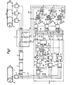
Fig. 1 zeigt ein Ausführungsbeispiel für eine Schaltungsanordnung zur Selektiv-Farbkorrektur bei einem Farbscanner, mit der Farbauszüge für den Mehrfarben-Mischdruck (Papierdruck) hergestellt werden.1 shows an exemplary embodiment of a circuit arrangement for selective color correction in a color scanner, with which color separations for multicolor mixed printing (paper printing) are produced.
Eine Farbvorlage 1, von der Farbauszüge für den Mehrfarben-Mischdruck hergestellt werden sollen, befindet sich auf einer rotierenden Abtasttrommel 2 eines nicht näher dargestellten Farbscanners und wird von einem optoelektronischen Abtastorgan 3 punkt- und zeilenweise, trichromatisch abgetastet. Das von der abgetasteten Farbvorlage 1 reflektierte oder durchgelassene Abtastlicht wird im optoelektronischen Abtastorgan 3 mit Hilfe von Farbteilern, Korrekturfiltern und optoelektronischen Wandlern in die Farbmeßwert-Signale R, G und B umgewandelt, welche ein Maß für die Intensitäten der Grundfarbenanteile "Rot", "Grün" und "Blau" an den abgetasteten Farben sind. Das optoelektronische Abtastorgan 3, welches axial zur Abtasttrommel 2 verschiebbar ist, wird sowohl zum Ausmessen einzelner Farbpunkte in der Farbvorlage 1 als auch zum flächenmäßigen, punkt-und zeilenweisen Abtasten der Farbvorlage 1 während der eigentlichen Aufzeichnung der Farbauszüge verwendet. Ein Ausführungsbeispiel für ein optoelektronisches Abtastorgan zeigt Fig. 8.A
Die Farbmeßwert-Signale R, G, und B gelangen über Leitungen 4 an eine Logarithmier-Stufe 5, in der sie in Farbmeßwert-Signale R', G' und BI logarithmiert oder teillogarithmiert und gegebenenfalls noch nach einer Gradationsfunktion nichtlinear verändert werden. Der Logarithmier-Stufe 5 ist eine erste Farbkorrektur-Schaltung 6 zur Grund-Farbkorrektur nachgeschaltet, in der die Farbmeßwert-Signale RI, G' und BI nach den Gesetzmäßigkeiten der subtraktiven Farbmischung in die Farbauszugs-Signale Y, M und C zur Aufzeichnung der Farbauszüge "Gelb", "Magenta" und "Cyan" sowie gegebenenfalls noch in das Farbauszugs-Signal K für die Aufzeichnung des Farbauszuges "Schwarz" umgesetzt werden.The color measurement value signals R, G, and B pass via lines 4 to a
In einer Überlagerungs-Stufe 7 werden den grundkorrigierten Farbauszugs-Signalen Y, M und C Selektivkorrektur-Signale YK, MK und CK additiv überlagert. Die nunmehr zusätzlich selektiv korrigierten Farbauszugs-Signale Y', M' und C' gelangen von der Überlagerungs-Stufe 7 an Aufzeichnungsorgane 8, in Form von Schreiblampen, deren Helligkeiten durch die zugeordneten Farbauszugs-Signale Y', M' oder C' moduliert werden. Auf einer ebenfalls rotierenden Aufzeichnungstrommel 9 sind Aufzeichnungsmedien 10, z. B. Filme, aufgespannt. Die Aufzeichnungsorgane 8 bewegen sich gemeinsam axial an der Aufzeichnungstrommel 9 entlang und belichten punkt- und zeilenweise die aufgespannten Filme. Die belichteten und entwickelten Filme sind die gewünschten Farbauszüge für den Mehrfarben-Mischdruck.In a
Die im Abtastorgan 3 gewonnenen Farbmeßwert-Signale R, G und B werden über Leitungen 11 auf einen Signalerzeuger 12 gegeben.The color measurement value signals R, G and B obtained in the
Aufbau und Wirkungsweise des Signalerzeugers 12 soll nachfolgend näher erläutert werden, und zwar für den Fall, daß bei der Herstellung der Farbauszüge ein ausgewählter Farbton, nachfolgend mit Korrekturfarbton bezeichnet, selektiv korrigiert werden soll. Die Farbmeßwert-Signale R, G und B auf den Leitungen 11 werden zunächst in einer Umformer-Stufe 13 logarithmiert oder teillogarithmiert und gegebenenfalls nach einer Gradationskurve korrigiert. Die logarithmierten Farbmeßwert-Signale R', G' und BI werden durch eine Matrizierung gemäß Gleichungen (1) in Chrominanz-Signale x und y und ein Luminanz-Signal z umgeformt.
![]()

![]()
Die Matrizierung entspricht einer Transformation der Farbkoordinaten des kartesischen RGB-Farbraumes in die Farbkoordinaten x, y und z des kartesischen Chrominanz/ Luminanz-Farbraumes, in dem die Farbkoordinaten x und y die Lage der Farborte der Farben in der Chrominanzebene und die Farbkoordinate z die Helligkeitswerte der Farben kennzeichnen.The matrixing corresponds to a transformation of the color coordinates of the Cartesian RGB color space into the color coordinates x, y and z of the Cartesian chrominance / luminance color space, in which the color coordinates x and y represent the position of the color locations of the colors in the chrominance plane and the color coordinate z the brightness values of the colors.
Der gewünschte Korrekturfarbton T0 wird zunächst durch Vorgabe eines Farbmeßwert-Tripels R0, G0 und B0 bzw. durch Vorgabe seiner durch Matrizierung gebildeten Chrominanzwerte x0 und y0 oder durch Ausmessen eines Probenpunktes in der Farbvorlage 1 mit Hilfe des optoelektronischen Abtastorgans 3 definiert. Die Chrominanzwerte x0 und yo werden erfindungsgemäß durch eine auf den ausgewählten Korrekturfarbton TO einstellbarer Matrizierung nach Gleichungen (2) in entsprechende Chrominanzwerte x'0 und y'0 transformiert, wobei die Transformationskoeffizienten a, b, c und d so bestimmt werden, daß die Bedingungen x'0>0 und y'0 = 0 erfüllt sind.
![]()
![]()
Im gewählten Ausführungsbeispiel werden vorzugsweise Transformationskoeffizienten in der Form b = e = cosα und c = -d = sinx verwendet, so daß die Matrizierung einer Drehung eines X'Y'-Farbkoordinatensystems um einen . Winkel α gegenüber dem ursprünglichen XY-Farbkoordinatensystem nach Gleichungen (3) entspricht.![]()

![]()
Der zur Erfüllung der Bedingungen x'0>0 und y'0 = 0 erforderliche Winkel α0 wird in einer Transformations-Stufe 14 durch einen automatischen Abgleichvorgang bei laufender Überprüfung der Bedingungen x'0>0 und y'0 = 0 in einer internen Überwachungs-Stufe der Transformations-Stufe 14 bestimmt, indem der Winkelα solange verändert wird, bis die Überwachungs-Stufe die Erfüllung der Bedingungen festgestellt hat. Der dabei gefundene Winkel α0 = arc tan y0/x0 entspricht dem Korrekturfarbton T0, und die X'-Achse des um den Winkel α0 gedrehten X'Y'-Farbkoordinatensystems verläuft durch den in die Chrominanzebene transformierten Farbort F'0 des Korrekturfarbtons TO. Die beschriebene Koordinaten-Drehung entspricht einer Drehung des Chrominanz/Luminanz-Farbraumes um die Luminanz-Achse (Z).The to satisfy the conditions x '0> 0 and y' 0 = 0 required angle α 0 is in a transformation stage 14 x by an automatic balancing operation for constantly checking the
Der gefundene Winkel α0 wird in der Transformations-Stufe 14 gespeichert und bei der Aufzeichnung der Farbauszüge zur laufenden Transformation der Chrominanz-Signale x und y in die gedrehten Chrominanz-Signale x' und yl gemäß Gleichungen (4) verwendet, wobei das gedrehte Chrominanz-Signal y' von Null verschieden ist für alle Farbtöne der abgetasteten Farben, die von dem ausgewählten Korrekturfarbton T0 abweichen und gleich Null ist für alle Farbtöne, die mit dem ausgwählten Korrekturfarbton T0 übereinstimmen.
![]()
![]()
Es liegt im Rahmen der Erfindung, die Matrizierung nach Gleichungen (1) und (4) in einem Schritt durchzuführen.It is within the scope of the invention to perform the matrixing according to equations (1) and (4) in one step.
Ein detailliertes Ausführungsbeispiel für die Transformations-Stufe 14 wird in Fig. 9 angegeben.A detailed exemplary embodiment for the
Die zuvor beschriebene Koordinaten-Drehung wird anhand einer grafischen Darstellung in Fig. 2 nochmals verdeutlicht.The previously described coordinate rotation is illustrated once again with the aid of a graphic representation in FIG. 2.
Fig. 2 zeigt die Chrominanzebene des Chrominanz/Luminanz-Farbraumes mit dem XY-Farbkoordinatensystem 15, wobei die Z-Achse (Grauachse) des Chrominanz/Luminanz-Farbraumes senkrecht zur Chrominanzebene verläuft. Ein transformierter Farbort F'0 eines ausgewählten Korrekturfarbtons T0 ist im XY-Farbkoordinatensystem 15 durch die Farbkoordinaten x0 und yo definiert. Gleichzeitig ist das um den Winkel α0 gedrehte X'Y'-Farbkoordinatensystem 16 dargestellt, dessen X'-Achse durch den transformierten Farbort F'0 verläuft, so daß der transformierte Farbort F'0 im gedrehten X'Y'-Farbkoordinatensystem 16 die Farbkoordinaten x'0>0 und yl 0 = 0 aufweist. Der Winkel α0 = arc tan y0/x0 entspricht dem Korrekturfarbton T0 im XY-Farbkoordinatensystem 15. Gleichzeitig ist symmetrisch zur X'-Achse des gedrehten X'Y'-Farbkoordinatensystems 16 ein sektorförmiger Farbton-Bereich 17 um den Korrekturfarbton T0 dargestellt, dessen Grenzwinkel βg (Öffnungswinkel 2 βg) bezogen auf die X'-Achse zur Eingrenzung der Korrekturfarbtöne T0 einstellbar ist. Für einen beliebigen Farbort F' innerhalb des Farbton-Bereiches 17 entspricht in erster Näherung bei kleinem Winkel β das gedrehte Chrominanz-Signal x' der Farbsättigung und der Quotient y'/x' = tan β der Abweichung des Farbtons der abgetasteten Farben von dem ausgewählten Korrekturfarbton T0, wobei der Quotient mit wachsender Abweichung ansteigt.2 shows the chrominance plane of the chrominance / luminance color space with the XY color coordinate
Außerdem zeigt Fig. 2 noch die zu den abgegrenzten Korrekturfarbtönen gehörenden Komplementärfarbtöne innerhalb eines Sektors 18, der durch Spiegelung des Farbton-Bereiches 17 an der Y'-Achse des X'Y'-Farbkoordinatensystems 16 entstanden ist. Das gedrehte Chrominanz-Signal x' ist für die abgegrenzten Farbtöne positiv, dagegen für die Komplementärfarbtöne negativ. Bei der Herstellung von-Farbauszügen erweist es sich sehr oft als notwendig, Farbschwankungen oder Verläufe im "Grau" einheitlich zu korrigieren. Von einem solchen zylindrischen oder tonnenförmigen Bereich um die Grauachse 19 ist in Fig. 2 noch die Schnittfläche 20 dargestellt, deren Radius durch einen Grenz-Farbsättigungswert x'g definiert ist.In addition, FIG. 2 also shows the complementary color tones belonging to the delimited correction color tones within a
Das in der Transformations-Stufe 14 erzeugte gedrehte Chrominanz-Signal x' wird über eine Leitung 21 einer Auswahl-Stufe 22 in Form einer Dioden-Schaltung zugeführt, welche nur die positiven Werte des gedrehten Chrominanz-Signals x' als Signal +x' durchläßt. Am Ausgang der Auswahl-Stufe 22 erscheint somit immer nur dann ein Signal, wenn die Farbtöne der von der Farbvorlage 1 abgetasten Farben, bezogen auf die Y'-Achse des gedrehten X'Y'-Farbkoordinatensystems 16 (Fig. 2), auf der Seite des abgegrenzten Farbton-Bereiches 17, liegen, wenn es sich also um keine Komplementärfarbtöne handelt, so daß in vorteilhafter Weise eine exakte Trennung von Farbtönen und Komplementärfarbtönen erreicht wird. Das Signal +x' ist näherungsweise ein Maß für die Farbsättigung. Das gedrehte Chrominanz-Signal y' gelangt von der Transformations-Stufe 14 über eine Leitung 23 auf eine Betrags-Stufe 24. In der Betrags-Stufe 24 wird der Betrag des gedrehten Chrominanz-Signals y' als Signal/y'/gebildet.The rotated chrominance signal x 'generated in the
Durch amplitudenmäßige Einstellung des Signals/y'/ mittels eines Potentiometers 25 wird der Grenzwinkel βg für den gewünschten Farbton-Bereich 17 (Fig. 2) festgelegt. Die Signale +x' und/y'/werden über Leitungen 26 und 27 einer Dividier-Stufe 28 zugeführt, in der durch Quotientenbildung ein Farbton-Signal T' gemäß Gleichung (5) gewonnen wird.
Das Farbton-Signal T' liefert eine Aussage über die betragsmäßige Abweichung des Farbtones eine auf der Farbvorlage 1 abgetasteten Farbe von dem ausgewählten Korrekturfarbton T0 nach beiden Richtungen hin, wobei bei Farbton-Übereinstimmung (β = 0) das Farbton-Signal T' = 0 ist. Das Farbton-Signal T' kann in der Dividier-Stufe 28 auch noch amplituden- und formmäßig verändert werden.The hue signal T 'provides information about the amount of the hue in terms of the amount of a color sampled on the
Fig. 3 zeigt verschiedene Verläufe des Farbton-Signals T' in Abhängigkeit des Winkels β. Die Verläufe 29 und 30 ergeben sich bei unterschiedlich eingestellten Grenzwinkeln βg des Farbton-Bereiches 17 für den Fall, daß in der Dividier-Stufe 28 keine zusätzliche Signalbeeinflussung stattfindet. Der Verlauf 31 ergibt sich, wenn das Farbton-Signal T' in der Dividier-Stufe 28 im Bereich kleiner Winkel β verflacht wird.Fig. 3 shows different courses of the hue signal T 'depending on the angle β. The
In einer Differenz-Stufe 32 wird aus dem Farbton-Signal T' und einem Hilfssteuersignal H nach Gleichung (6) ein Farbton-Steuersignal T erzeugt.![]()
![]()
Das Hilfssteuersignal H, das in einem Signalgenerator 33 erzeugt wird, hat beispielsweise einen konstanten Wert H0, der dann vorzugsweise H0 = tan y0/x0 gewählt wird. Vorteilhafter ist es aber, das Hilfssteuersignal H, wie im beschriebenen Ausführungsbeispiel, in erster Näherung von der Farbsättigung, d. h. vom Signal +x', abhängig zu machen. In diesem Falle hat das Hilfssteuersignal H = f (x') von einem maximalen Farbsättigungswert bis in die Nähe des bereits in Fig. 2 erläuterten Grenz-Farbsättigungswertes x'g den konstanten Wert H0, fällt dann ab und hat zwischen dem Grenz-Farbsättigungswert x'g und der Grauachse (x' = 0) den Wert Null. Fig. 10 zeigt ein Ausführungsbeispiel für den Signalgenerator 33.The auxiliary control signal H, which is generated in a
In Fig. 4 sind verschiedene Verläufe des Farbton-Steuersignals T* in Abhängigkeit des Winkels β für verschiedene Grenzwinkel βg der Farbton-Bereiche 17 und für ein konstantes Hilfssteuersignal H0 bzw. für den zwischen dem Grenz-Farbsättigungswert x' und dem maximalen Farbsättigungswert liegenden Bereich des Hilfssteuersignals H = f (x') dargestellt. Das Farbton-Steuersignal T* hat für Farbtöne der abgetasteten Farben, die dem ausgewählten Korrekturfarbton T0 entsprechen ( β = 0), einen maximalen Wert T*m = H0, der bei H0 = tan y0/x0 genau dem Korrekturfarbton T0 entspricht. Mit steigender Abweichung der Farbtöne der abgetasteten Farben von dem Korrekturfarbton T0 fällt das Farbton-Steuersignal T* ab und erreicht bei dem jeweiligen Grenzwinkel βg der eingestellten Farbton-Bereiche 17 den Wert T = 0.4 shows different courses of the hue control signal T * as a function of the angle β for different limit angles β g of the
Alternativ zur Einstellung des Grenzwinkels βg des Farbton-Bereiches 17 mit Hilfe des Potentiometers 25 kann der Grenzwinkel βg auch durch Amplitudenänderung des Farbton-Signals T' in der Dividier-Stufe 28 oder des Wertes H0 des Hilfssteuersignals H in dem Signalgenerator 33 eingestellt werden.As an alternative to setting the limit angle β g of the
Fig. 5 zeigt verschiedene Verläufe des Farbton-Steuer- * signals T in Abhängigkeit des Signals x' bzw. der Farbsättigung für den Fall, daß das Hilfssteuersignal H = f (x') und der Winkel β Parameter sind. Durch die Abhängigkeit des Farbton-Steuersignals T von der Farbsättigung wird in vorteilhafter Weise eine Abgrenzung nach "Grau" erreicht.Fig. 5 shows different courses of the hue control * signal T as a function of the signal x 'or the color saturation in the event that the auxiliary control signal H = f (x') and the angle β are parameters. Due to the dependence of the hue control signal T on the color saturation, a delimitation according to "gray" is advantageously achieved.
Wenn eine ausgewählte Farbe der Farbvorlage 1, nachfolgend mit Korrekturfarbe bezeichnet, bei der Herstellung der Farbauszüge selektiv korrigiert werden soll, muß ein dreidimensionaler Farb-Bereich im Farbton/ Farbsättigung/Luminanz-Farbraum abgegrenzt werden, indem der sektorförmige Farbton-Bereich zusätzlich hinsichtlich der Helligkeit und/oder der Farbsättigung * eingegrenzt wird und ein Farb-Steuersignal F erzeugt wird.If a selected color of the
Zur Eingrenzung bezüglich der Helligkeit wird in einem Luminanz-Signalgenerator 34, dem die Farbmeßwert-Signale R, G und B über die Leitungen 11 zugeführt werden, aus mindestens einem, vorzugsweise aus allen drei Farbmeßwert-Signalen R, G und B ein Luminanz-Signal L' gemäß der Beziehung L' = f1 R + f 2 G + f 3 B gewonnen. Als Luminanz-Signal L' kann auch das in der Umformer-Stufe 13 gebildete Luminanz-Signal z verwendet werden, falls an der Bildung des Luminanz-Signals L' alle drei Farbmeßwert-Signale R, G und B beteiligt sind. In diesem Falle kann der Luminanz-Signalgenerator 34 entfallen.To limit the brightness, in a
Zur Eingrenzung bezüglich der Farbsättigung erzeugt ein Farbsättigungs-Signalgenerator 35 ein Farbsättigungs-Signal S'. Das Farbsättigungs-Signal S' kann gemäß der Gleichung ![]()
![]()
Dem Luminanz-Signalgenerator 34 ist eine Begrenzer-Stufe 37 nachgeschaltet, in der aus dem Luminanz- Signal L' ein Luminanz-Steuersignal L erzeugt wird. Ebenso ist dem Farbsättigungs-Signalgenerator 35 eine entsprechende Begrenzer-Stufe 38 nachgeschaltet, welche das Farbsättigungs-Signal S' in ein Farbsättigungs- * Steuersignal S umwandelt. Die Bildung des Luminanz- * Steuersignals L und des Farbsättigungs- * Steuersignals S erfolgt durch Verschiebung der Einsatzpunkte des Luminanz-Signals L' bzw. des Farbsättigungs-Signals S' mit Hilfe von Kompensationsspannungen, welche an Potentiometern 39 und 40 bzw. 41 und 42 einstellbar sind. Gleichzeitig können das Luminanz-Signal L' und das Farbsättigungs-Signal S' in den Begrenzer-Stufen 37 und 38 noch amplitudenmäßig und/ oder nach Gradationskurven nichtlinear verändert werden.The
Ein Ausführungsbeispiel für die identisch aufgebauten Begrenzer-Stufen 37 und 38 zeigt Fig. 12. Die Begrenzer-Stufen 37 und 38 können aber auch als einfache * Inverter aufgebaut sein, in denen L = const. - L' * bzw. S = const. - S' gebildet wird.An exemplary embodiment for the identically constructed limiter stages 37 and 38 is shown in FIG. 12. The limiter stages 37 and 38 can also be constructed as simple * inverters in which L = const. - L '* or S = const. - S 'is formed.
* Luminanz-Steuersignal L und/oder Farbsättigungs- * Steuersignal S werden über Schalter 43 und 44 auf die Differenz-Stufe 32 gegeben, in der das Farb-Steuersignal * F gemäß Gleichung (7) gebildet wird.![]()

![]()
Alternativ kann das Farb-Steuersignal F* auch durch Multiplikation der entsprechenden Signale gewonnen werden. Mit Hilfe der Potentiometer 39 und 40 bzw. 41 und 42 an den Begrenzer-Stufen 37 und 38 können die Helligkeits- und Farbsättigungswerte festgelegt werden, bei denen die Helligkeit und die Farbsättigung der abgetasteten Farben Einfluß auf den Verlauf des Farb- * Steuersignals F nehmen. Mit Hilfe der Schalter 43 und 44 kann außerdem eine Auswahl der Signale getroffen werden, die an der Bildung des Farb-Steuersignals F beteiligt werden sollen.Alternatively, the color control signal F * can also be obtained by multiplying the corresponding signals. With the help of the
Der Verlauf des Farb-Steuersignals F in bezug auf den Farbton der abgetasteten Farben entspricht dem in Fig. 4. dargestellten Verlauf des Farbton-Steuersignals T , wenn Helligkeit und Farbsättigung unberücksichtigt bleiben.The course of the color control signal F with respect to the hue of the sampled colors corresponds to the course of the hue control signal T shown in FIG. 4 if brightness and color saturation are not taken into account.
Fig. 6 zeigt verschiedene, durch die Potentiometer 39 bis 42 an den Begrenzer-Stufen 37 und 38 einstellbare * Verläufe des Luminanz-Steuersignal L in Abhängigkeit der Helligkeit bzw. des Farbsättigungs-Steuersignals S in Abhängigkeit der Farbsättigung.6 shows various * profiles of the luminance control signal L as a function of the brightness or of the color saturation control signal S as a function of the color saturation, which can be adjusted by the
In Fig. 7 sind die zugehörigen Verläufe des Farb- Steuersignals F in Abhängigkeit der Helligkeit bzw. der Farbsättigung dargestellt. Zur Vereinfachung der Darstellung ist angenommen, daß der abgetastete Farbton gerade dem ausgewählten Korrekturfarbton T0 entspricht.7 shows the associated courses of the color control signal F as a function of the brightness or the color saturation. To simplify the illustration, it is assumed that the sampled hue corresponds exactly to the selected correction hue T 0 .
Sollen im wesentlichen dunkle Farben korrigiert werden, wird mit Hilfe eines der Potentiometer an der Begrenzer-Stufe 37 z. B. der Verlauf 45 des Luminanz-Steuersignals L* eingestellt, wodurch sich der Verlauf 451 des Farb-Steuersignals F ergibt. In diesem Falle hat das Farb-Steuersignal F bei dunklen Farben einen hohen Signalpegel,'und die Signalbegrenzung setzt erst bei helleren Farben ein.If essentially dark colors are to be corrected, use one of the potentiometers at the
Sollen dagegen im wesentlichen helle Farben korrigiert werden, wird mit Hilfe des anderen Potentiometers an der Begrenzer-Stufe 37 beispielsweise der Verlauf 46 eingestellt, und es ergibt sich der Verlauf 461 des Farb-Steuersignals F . In diesem Falle hat das Farb-Steuersignal F* bei hellen Farben einen hohen Signalpegel, der zu dunklen Farben hin begrenzt wird. Auf diese Weise können in vorteilhafter Weise zu korrigierende helle und dunkle Farben exakt voneinander getrennt werden.If, on the other hand, essentially bright colors are to be corrected, the
Zur Abgrenzung eines Helligkeits-Bereiches kann mit Hilfe beider Potentiometer an der Begrenzer-Stufe 37 * auch der Verlauf 47 des Luminanz-Steuersignals L erzeugt werden. In diesem Falle hat das Farb- Steuersignal F den Verlauf 471, wodurch eine Begrenzung zu hellen und dunklen Farben um Farben mittlerer Helligkeit erreicht wird. So lassen sich im wesentlichen Farben korrigieren, die in oder in der Nähe der Chrominanzebene liegen.To delimit a brightness range, the
Durch eine sinngemäße Einstellung der Potentiometer an der Begrenzer-Stufe 38 kann eine Abgrenzung der zu korrigierenden Farben hinsichtlich kleiner oder großer Farbsättigungswerte sowie hinsichtlich eines Farbsättigungs-Bereiches vorgenommen werden.By appropriately adjusting the potentiometers at the
Die im Signalerzeuger 12 gebildeten Signale werden auf ein Koppelfeld 46 gegeben, und zwar das angenäherte Farbsättigungs-Signal S'' = x' über eine Leitung 47, das Hilfssteuersignal H vom Signalgenerator 33 über eine Leitung 48, wahlweise das Farbton-Steuersignal T oder das Farb-Steuersignal F von der Differenz-Stufe 32 über eine Leitung 49, das Farbsättigungs- Steuersignal S von der Begrenzer-Stufe 38 über eine Leitung 50, das Farbsättigungs-Signal S' vom Farbsättigungs-Signalgenerator 35 über eine Leitung 51, das * Luminanz-Steuersignal L von der Begrenzer-Stufe 37 über eine Leitung 52 und das Luminanz-Signal L' vom Luminanz-Signalgenerator 34 über eine Leitung 53.The signals formed in the
Im Koppelfeld 46 werden diejenigen Signale ausgewählt, die hinsichtlich Farbton, Farbsättigung oder Helligkeit in zweckmäßiger Weise an der Bildung der Selektiv-Korrektursignale beteiligt werden sollen, und auf eine Anzahl von Verknüpfungs-Stufen, im Ausführungsbeispiel auf die Verknüpfungs-Stufen 54, 55 und 56, gegeben, die dem Koppelfeld 46 nachgeschaltet sind. In den Verknüpfungs-Stufen 54, 55 und 56 werden jeweils aus mindestens einem der im Koppelfeld 46 zur Verfügung stehenden Signale positive Ausgangssignale +A bzw. +B und +C abgeleitet, welche gleichzeitig in Invertern 57, 58 und 59 in entsprechende negative Ausgangssignale -A bzw. -B und -C invertiert werden. Zwischen jedem positiven und negativen Ausgangssignalpaar ist ein Tripel von Potentiometern 60, 61 und 62 geschaltet. An jedem Tripel von Potentiometern 60, 61 und 62 wird ein Korrektursignal-Tripel (YA, MA, CA), (Y BI MB, C B) und (YC, MC, CC) abgegriffen, wobei durch die gewählte Potentiometereinstellung sowohl der Betrag als auch das Vorzeichen der Korrektursignale und damit die Korrekturstärke und die Korrekturrichtung (positiv/ negativ) bestimmt werden.In the switching
Die Korrektursignal-Tripel werden über Summierwiderstände 63, 64 und 65 zu den Selektiv-Korrektursignalen YK, MK und CK für die Farbauszugs-Signale Y, M und C vereinigt und über Leitungen 66 an die Überlagerungs-Stufe 7 gegeben.The correction signal triples are combined via summing
Einige Beispiele sollen die Bildung der Selektiv-Korrektursignale YK, MK und CK erläutern.Some examples are intended to explain the formation of the selective correction signals Y K , M K and C K.
Wenn ein bestimmter Farbton der Farbvorlage 1 selektiv zu korrigieren ist, wird der entsprechende Korrekturfarbton T0, wie ausführlich erläutert, in dem Signalerzeuger 12 voreingestellt und die Selektiv-Korrektursignale YK, MK und CK aus dem Farbton-Steuersignal T abgeleitet.If a specific hue of the
Wenn eine Farbe mit der Farbvorlage 1 selektiv korrigiert werden soll, wird im Signalerzeuger 12 der Farbton-Bereich zusätzlich hinsichtlich Helligkeit und Farbsättigung abgegrenzt und die Selektiv-Korrektur- signale YK, MK und CK aus dem Farb-Steuersignal F abgeleitet.If a color is to be corrected selectively with the
Die Selektiv-Korrektursignale YK, MK und CK sind, wie aus den dargestellten Verläufen des Farbton- * Steuersignals T und des Farb-Steuersignals F hervorgeht, bei Abtastung des Korrekturfarbtons in der Farbvorlage maximal, nehmen mit wachsendem Abstand der abgetasteten Farbtöne von dem eingestellten Korrekturfarbton ab und erreichen den Wert Null, wenn die abgetasteten Farbtöne am Rande des abgegrenzten Farbton- bzw. Farb-Bereiches liegen. Man erhält somit in vorteilhafter Weise verlaufende Selektiv-Korrektursignale, die sich optimal an die Farbverläufe in den Farbtönen oder Farben der abgetasteten Farbvorlage 1 anpassen.The selective correction signals Y K , M K and C K are, as can be seen from the curves of the hue * control signal T and the color control signal F, maximum when scanning the correction hue in the color template, decrease with increasing distance of the sampled hues from the set correction color and reach the value zero when the sampled color tones lie on the edge of the defined color or color range. In this way, selective correction signals are obtained which advantageously adapt to the color gradients in the hues or colors of the scanned
Manchmal erweist es sich als zweckmäßig, einen bestimmten Farbton proportional zur Farbsättigung zu korrigieren. In diesem Falle wird beispielsweise das Farbton-Steuersignal T mit dem Farbsättigungs-Signal S' in der Verknüpfungs-Stufe 54 miteinander verknüpft. Dadurch ergeben sich Selektiv-Korrektursignale YK, MK und CKI welche im Graubereich bis zum Grenz-Farbsättigungswert x'g nahezu unwirksam sind, während sie für bunte Farben (hohe Farbsättigungswerte) nicht von der Farbsättigung beeinflußt werden und nur vom Farbton abhängen.Sometimes it is useful to correct a certain hue in proportion to the color saturation. In this case, for example, the hue control signal T is linked with the color saturation signal S 'in the
In einem weiteren Beispiel sollen helle Farben, sogenannte Pastellfarben, selektiv korrigiert werden. In diesem Falle erweist es sich als zweckmäßig, entsprechende Korrektursignale YB, MB und CB durch multiplikative Verknüpfung des Luminanz-Signals L' mit dem Farbsättigungs-Steuersignal S , das in der Begrenzer-Stufe 39 durch Invertierung des Farbsättigungs-Signals S' entstanden ist, in der Verknüpfungs-Stufe 55 zu bilden. Die Korrektursignale YB, MB und CB sind dann in einem Teilfarbraum wirksam. Die Flächen konstanter Signalgröße haben die Form eines Kegels, der mit der Spitze bei Schwarz liegt und dessen Kegelachse die Grauachse ist, wobei die Korrektursignale außerhalb der Kegeloberfläche Null sind und nach dem Inneren zu ansteigen.In another example, light colors, so-called pastel colors, are to be selectively corrected. In this case, it proves to be appropriate to use corresponding correction signals Y B , M B and C B by multiplicative linking of the luminance signal L 'with the color saturation control signal S, which is generated in the
In einem weiteren Beispiel sollen nur die bunten Pastellfarben beeinflußt, die Graugradation dagegen unverändert beibehalten werden. Dann erweist es sich als zweckmäßig, Korrektursignale YC, MC und Cc durch multiplikative Verknüpfung des Luminanz-Signals L', des Farbsättigungs-Signals S' und des Farbsättigungs-Steuersignals S , das wiederum durch Invertierung des Farbsättigungs-Signals S' in der Begrenzer-Stufe 39 entstanden ist, in der Verknüpfungs-Stufe 56 zu gewinnen. Dann steigen die Korrektursignale YC, MC und CC von der Kegeloberfläche zunächst wieder nach innen an und fallen mit weiterer Annäherung an die Grauachse wieder auf Null ab.In another example, only the bright pastel colors are to be influenced, while the gray gradation is to remain unchanged. Then it proves expedient to correct the correction signals Y C , M C and C c by multiplying the luminance signal L ', the color saturation signal S' and the color saturation control signal S, which in turn by inverting the color saturation signal S 'in the
Die Erfindung ist selbstverständlich nicht auf die zuvor beschriebenen Beispiele für die Bildung von Selektiv-Korrektursignalen beschränkt.The invention is of course not limited to the examples for the formation of selective correction signals described above.
Fig. 8 zeigt ein Ausführungsbeispiel für das optoelektronische Abtastorgan 3. Das von der Farbvorlage 1 reflektierte oder durchgelassene Abtastlicht 67 gelangt durch Objektive 68 und 69 und durch eine Blende 70 in das Abtastorgan 3 und wird dort mittels zweier dichroitischer Farbteiler 71 und 72 in drei Teilbündel 73, 74 und 75 aufgespalten. Die Teilbündel 73, 74 und 75 fallen durch Korrektur-Farbfilter 76, 77 und 78 auf drei optoelektronische Wandler 79, 80 und 81, die das empfangene Teillicht entsprechend den Intensititäten der Grundfarben-Anteile an den abgetasteten Farben in die primären Farbmeßwert-Signale R, G und B umwandeln.8 shows an exemplary embodiment of the
Fig. 9 zeigt ein Ausführungsbeispiel für die Transformations-Stufe 14.9 shows an exemplary embodiment for the
In der Transformations-Stufe 14 werden die Chrominanz-Signale x0 und y0 des ausgewählten Korrekturfarbtons T0 während eines Abgleichvorganges durch monotone Änderung des Winkels α gedreht, bis die gedrehten Chrominanz-Signale x'0>0 und y'0 = 0 sind, wobei der dabei gefundene Winkel α0 festgehalten wird. Diese Koordinaten-Drehung läuft gemäß Gleichung (3) ab.In the
Während der punkt- und zeilenweisen Abtastung der selektiv zu korrigierenden Farbvorlage 1 werden dann die laufend erzeugten Chrominanz-Signale x und y gemäß Gleichung (4) gedreht.The continuously generated chrominance signals x and y are then rotated according to equation (4) during the point-by-line and line-by-line scanning of the
Die Transformations-Stufe 14 besteht aus vier Multiplizier-Stufen 82, 83, 84 und 85, einer Addier-Stufe 86, eine Subtrahier-Stufe 87, einem Festwert-Speicher 88, einem Adreßzähler 89, einer Tor-Stufe 90, einem Taktgenerator 91 sowie aus einer Überwachungs-Stufe 92.The
Die Multiplizier-Stufen 82, 83, 84 und 85 sind in vorteilhafter Weise aus multiplizierenden D/A-Wandlern, z. B. aus integrierten Bausteinen vom Typ AD 7542 der Firma Analog Devices aufgebaut. In einen solchen multiplizierenden D/A-Wandler kann ein wählbarer Faktor in Form von Digitalwerten über einen Dateneingang eingegeben werden, die in einem internen Register speicherbar sind. Ein am Eingang des multiplizierenden D/A-Wandlers anstehendes analoges Signal wird mit dem eingestellten Faktor multipliziert, wobei das Produkt wiederum als analoges Signal am Ausgang des multiplizierenden D/A-Wandlers zur Verfügung steht.The multiplier stages 82, 83, 84 and 85 are advantageously made of multiplying D / A converters, e.g. B. built from integrated blocks of type AD 7542 from Analog Devices. In such a multiplying D / A converter, a selectable factor in the form of digital values can be entered via a data input, which can be stored in an internal register. An analog signal present at the input of the multiplying D / A converter is multiplied by the set factor, the product in turn being available as an analog signal at the output of the multiplying D / A converter.
Während des Abgleichvorganges wird das von der gestrichelt angedeuteten Umformer-Stufe 13 kommenden Chrominanz-Signal x0 auf die Eingänge 93 und 94 der Multiplizier-Stufen 82 und 83 gegeben, während das Chrominanz-Signal y0 auf die Eingänge 95 und 96 der Multiplizier-Stufen 84 und 85 gelangt.During the adjustment process, this comes from the
Im Festwert-Speicher 88 sind für Winkelwerte von 0 - 3600 die entsprechenden Sinus- und Cosinus-Werte als Digitalwerte b = e = cosαund c = d = sinα durch die zugehörigen Winkelwerteα als Adressen des Festwert-Speichers 88 abrufbar gespeichert. Der Datenausgang 97 des Festwert-Speichers 88 für die Digitalwerte b = e = cosα ist über einen Daten-Bus 98 mit den Dateneingängen 99 und 100 der Multiplizier-Stufen 82 und 85 und der entsprechende Datenausgang 101 für die Digitalwerte c = d = sin α über einen Daten-Bus 102 mit den Dateneingängen 103 und 104 der Multiplizier-Stufen 83 und 84 verbunden.The corresponding sine and cosine values for digital values b = e = cosα and c = d = sinα are stored in the fixed
Der einschaltbare Taktgenerator 91 steht über die Tor-Stufe 90 mit dem Takteingang 105 des Adreßzählers 89 in Verbindung. Der Ausgang 106 des Adreßzählers 39 ist über einen Adreß-Bus 107 an den Adreßeingang 108 des Festwert-Speichers 88 angeschlossen. Die Ausgänge 109 und 110 der Multiplizier-Stufen 82 und 84 stehen mit der Addier-Stufe 86 und die Ausgänge 111 und 112 der Multiplizier-Stufen 83 und 85 mit der Subtrahier-Stufe 87 in Verbindung. Der Ausgang der Addier-Stufe 86 und der Ausgang der Subtrahier-Stufe 87 sind an die Überwachungs-Stufe 92 für die Bedingungen x'0>0 und y1 0 = 0 angeschlossen. Die Überwachungs-Stufe 92 steht mit einem Steuereingang 113 der Tor-Stufe 90 in Verbindung.The
Der Abgleichvorgang wird durch Einschalten des Taktgenerators 91 mit Hilfe einer Taste 114 eingeleitet. Der Zähltakt des Taktgenerators 91 wird in den Adreßzähler 89, der vorher rückgesetzt wurde, eingezählt, wobei der ansteigende zählerstand monoton ansteigenden Winkelwerten X entspricht. Der Adreßzähler 89 ruft nacheinander die Adressen des Festwert-Speichers 88 auf, die zu den WinkelwertenX gehörenden Digitalwerte cos α und sin α werden in die Multiplizier-Stufen 82, 83, 84 und 85 übertragen und dort mit den entsprechenden Chrominanz-Signalen x0 und y0 multipliziert. Die Einzelprodukte werden gemäß Gleichung (3) addiert bzw. voneinander subtrahiert, so daß an dem Ausgang der Addier-Stufe 86 das gedrehte Chrominanz-Signal x'0 und am Ausgang der Subtrahier-Stufe 87 das gedrehte Chrominanz-Signal y'0 erscheint. Dabei werden die gedrehten Chrominanz-Signale x'0 und y'0 laufend von der Überwachungs-Stufe 92 überprüft. Die Überwachungs-Stufe 92 gibt ein Steuersignal an die Tor-Stufe 90 ab, wenn die Bedingungen erfüllt sind, wodurch der Zähltakt unterbrochen wird. Der dabei erreichte Zählerstand im Adreßzähler 89 entspricht dem gesuchten Winkel α0.The adjustment process is initiated by switching on the
Fig. 10a zeigt ein Ausführungsbeispiel für den Signalgenerator 33 zur Erzeugung des Hilfssteuersignals H in Abhängigkeit des Signals x'.10a shows an exemplary embodiment of the
Der Signalgenerator 33 besteht aus einem invertierenden Verstärker 115, dessen Ausgang über eine Diode 116 und über ein Netzwerk 117 mit dem invertierenden Eingang des Verstärkers 115 verbunden ist. Der invertierende Eingang des Verstärkers 115 ist außerdem über einen ersten Summier-Widerstand 118 mit dem Signal x' beaufschlagt und über einen zweiten Summier-Widerstand 119 an ein Potentiometer 120 angeschlossen. An dem Potentiometer 120 kann eine Kompensationsspannung Uk1 eingestellt werden, die dem gewünschten Grenz-Farbsättigungswert x'g entspricht. Der nichtinvertierende Eingang des Verstärkers 115 ist über einen Widerstand 121 und die Anode der Diode 116 über einen Widerstand 122 an Massepotential gelegt. Bei Werten des Signals x', die betragsmäßig kleiner als die Kompensationsspannung Uk1 sind, ist das Hilfssteuersignal H = 0. Erreicht das Signal x' betragsmäßig die Kompensationsspannung Ukl' steigt das Hilfssteuersignal H entsprechend der im Netzwerk 117 eingestellten Verstärkung an und erreicht dann einen ebenfalls durch das Netzwerk 117 vorgegebenen Grenzwert HO.The
Fig. 10b zeigt den Verlauf des Hilfssteuersignals H am Ausgang des Signalgenerators 33.10b shows the profile of the auxiliary control signal H at the output of the
Fig. 11 zeigt ein Ausführungsbeispiel für den Farbsättigungs-Signalgenerator 35 zur Erzeugung des Farbsättigungs-Signals S' aus den Farbmeßwert-Signalen R, G und B.11 shows an exemplary embodiment of the color
Die vom nicht dargestellten Abtastorgan 1 gelieferten Farbmeßwert-Signale R, G und B werden in einer Logarithmier-Stufe 123 logarithmiert oder teillogarithmiert und gleichzeitig einer Maximumauswahl-Stufe 124 und einer Minimumauswahl-Stufe 125 zugeführt, welche aus den Farbmeßwert-Signalen R, G und B jeweils das maximale und minimale Farbmeßwert-Signal feststellen. In einer der Maximumauswahl-Stufe 124 und der Mininumauswahl-Stufe 125 nachgeschalteten Subtrahier-Stufe 126 wird das Farbsättigungs-Signal S' als Differenzsignal aus den festgestellten maximalen und minimalen Farbmeßwert-Signalen gebildet, welches näherungsweise der Farbsättigung entspricht.The color measurement value signals R, G and B, which are not shown by the
Fig. 12 zeigt ein Ausführungsbeispiel für die Begrenzer-Stufe 37 bzw. 38.12 shows an exemplary embodiment for the
Die Begrenzer-Stufe besteht aus drei identisch aufgebauten, invertierenden Verstärkern 127, 128 und 129. Die Ausgänge der Verstärker 127, 128 und 129 sind jeweils über Dioden 130, 131 und 132 und über Widerstände 133, 134 und 135 mit den invertierenden Eingängen der Verstärker 127, 128 und 129 verbunden. Die invertierenden Eingänge der Verstärker 127 und 128 sind über erste Summier-Widerstände 136 und 137 gemeinsam mit dem Farbsättigungs-Signal S' bzw. dem Luminanz-Signal L' beaufschlagt. Der invertierende Eingang des Verstärkers 127 ist über einen Summier-Widerstand 138 mit den Potentiometern 39 bzw. 41 und der invertierenden Eingang des Verstärkers 128 über einen Summier-Widerstand 139 mit den Potentiometern 40 bzw. 42 verbunden. Der invertierende Eingang des Verstärkers 129 ist über einen Summier-Widerstand 140 an den Ausgang des Verstärkers 127 und über einen weiteren Summier-Widerstand 141 an eine positive Spannungsquelle 142 angeschlossen. Die Ausgänge der Verstärker 128 und 129 stehen über Summier-Widerstände 143 und 144 mit dem invertierenden Eingang eines Begrenzer-Verstärkers 145 in Verbindung, dessen Ausgang über eine Parallelschaltung eines Widerstandes 146 mit einer Begrenzer-Diode 147 auf den invertierenden Eingang gekoppelt ist. Am Ausgang des Begrenzer-Verstärkers 145 steht das Farbsättigungs-Steuersignal S* bzw. das Luminanz-Steuersignal L* mit den in Fig. 6 dargestellten Verläufen zur Verfügung. Mit den Potentiometern 39 bzw. 41 und 40 bzw. 42 werden Kompensationsspannungen Uk2 und Uk3 eingestellt, welche die Einsatzpunkte der Spannungsbegrenzung bestimmen.The limiter stage consists of three identically constructed inverting
Claims (13)
Priority Applications (6)
| Application Number | Priority Date | Filing Date | Title |
|---|---|---|---|
| AT83112579T ATE29816T1 (en) | 1983-12-14 | 1983-12-14 | METHOD AND CIRCUIT ARRANGEMENT FOR SELECTIVE CORRECTION OF TONES AND COLOURS. |
| EP83112579A EP0145801B1 (en) | 1983-12-14 | 1983-12-14 | Method of and circuit arrangement for the selective correction of tints and colours |
| DE8383112579T DE3373765D1 (en) | 1983-12-14 | 1983-12-14 | Method of and circuit arrangement for the selective correction of tints and colours |
| US06/680,775 US4649423A (en) | 1983-12-14 | 1984-12-12 | Method and circuit arrangement for selective correction of hues and colors |
| CA000469977A CA1232841A (en) | 1983-12-14 | 1984-12-13 | Method and circuit arrangement for selective correction of hues and colors |
| JP59263099A JPS60146122A (en) | 1983-12-14 | 1984-12-14 | Method and device for preparing color separation plate for single color printing |
Applications Claiming Priority (1)
| Application Number | Priority Date | Filing Date | Title |
|---|---|---|---|
| EP83112579A EP0145801B1 (en) | 1983-12-14 | 1983-12-14 | Method of and circuit arrangement for the selective correction of tints and colours |
Publications (2)
| Publication Number | Publication Date |
|---|---|
| EP0145801A1 true EP0145801A1 (en) | 1985-06-26 |
| EP0145801B1 EP0145801B1 (en) | 1987-09-16 |
Family
ID=8190875
Family Applications (1)
| Application Number | Title | Priority Date | Filing Date |
|---|---|---|---|
| EP83112579A Expired EP0145801B1 (en) | 1983-12-14 | 1983-12-14 | Method of and circuit arrangement for the selective correction of tints and colours |
Country Status (6)
| Country | Link |
|---|---|
| US (1) | US4649423A (en) |
| EP (1) | EP0145801B1 (en) |
| JP (1) | JPS60146122A (en) |
| AT (1) | ATE29816T1 (en) |
| CA (1) | CA1232841A (en) |
| DE (1) | DE3373765D1 (en) |
Cited By (7)
| Publication number | Priority date | Publication date | Assignee | Title |
|---|---|---|---|---|
| DE3629195A1 (en) * | 1986-01-14 | 1987-07-23 | Canon Kk | COLOR IMAGE PROCESSING DEVICE |
| DE3629469A1 (en) * | 1986-08-29 | 1988-03-03 | Agfa Gevaert Ag | METHOD FOR ADJUSTING COLOR SATURATION IN ELECTRONIC IMAGE PROCESSING |
| DE3629403A1 (en) * | 1986-08-29 | 1988-03-03 | Agfa Gevaert Ag | METHOD FOR CORRECTING COLOR SATURATION IN ELECTRONIC IMAGE PROCESSING |
| EP0292212A2 (en) * | 1987-05-15 | 1988-11-23 | Canon Kabushiki Kaisha | Method of and apparatus for processing color image |
| EP0303474A2 (en) * | 1987-08-11 | 1989-02-15 | Canon Kabushiki Kaisha | Color image processing apparatus |
| DE4002298A1 (en) * | 1990-01-26 | 1991-08-01 | Agfa Gevaert Ag | METHOD AND DEVICE FOR THE AUTOMATIC CORRECTION OF COLOR TAPES IN ELECTRONIC IMAGE PROCESSING |
| WO2008036850A2 (en) * | 2006-09-21 | 2008-03-27 | Qualcomm Incorporated | Chroma supression features |
Families Citing this family (17)
| Publication number | Priority date | Publication date | Assignee | Title |
|---|---|---|---|---|
| US4745467A (en) * | 1985-10-28 | 1988-05-17 | Kabushiki Kaisha Toshiba | Color image-processing apparatus |
| US4763190A (en) * | 1986-06-30 | 1988-08-09 | Xerox Corporation | Digital color correction circuit |
| DE3751050T2 (en) * | 1986-11-14 | 1995-06-22 | Canon Kk | Color image processing device. |
| EP0281659B1 (en) * | 1987-03-13 | 1989-09-27 | Dr.-Ing. Rudolf Hell GmbH | Method and apparatus for white-level adjustment |
| IL86107A (en) * | 1988-04-18 | 1991-12-15 | Scitex Corp Ltd | Color conversion display apparatus and method |
| JPH07119128B2 (en) * | 1989-05-08 | 1995-12-20 | 三菱電機株式会社 | Color signal correction circuit |
| US5949556A (en) * | 1989-09-04 | 1999-09-07 | Canon Kabushiki Kaisha | Image processing suitable for changing the number of colors in an image |
| DE69031202T2 (en) * | 1989-10-13 | 1998-02-19 | Matsushita Electric Ind Co Ltd | Method and device for color compensation in color images |
| JP3011432B2 (en) * | 1990-05-14 | 2000-02-21 | 株式会社東芝 | Color image processing equipment |
| US5289295A (en) * | 1991-07-04 | 1994-02-22 | Matsushita Electric Industrial Co., Ltd. | Color adjustment apparatus |
| EP0536892B1 (en) * | 1991-10-07 | 1997-02-05 | Xerox Corporation | Image editing system and method have improved color key editing |
| JP2740409B2 (en) * | 1992-04-21 | 1998-04-15 | 大日本スクリーン製造株式会社 | Sharpness processing device |
| US5557688A (en) * | 1992-11-18 | 1996-09-17 | Fuji Photo Film Co., Ltd. | Method of extracting characteristic image data and color data conversion device for image processing apparatus |
| DE19632969C2 (en) | 1996-08-16 | 1999-04-29 | Roland Man Druckmasch | Method for determining standard values for the production of multicolored printed copies on a printing press |
| US5920358A (en) * | 1997-01-30 | 1999-07-06 | Fuji Photo Film Co., Ltd. | Method of transforming colors of image |
| US7190487B2 (en) * | 2001-09-25 | 2007-03-13 | Sharp Laboratories Of America, Inc. | Color conversion with hue straightening using multiple look-up tables and interpolation |
| US20070002180A1 (en) * | 2005-06-30 | 2007-01-04 | Lexmark International, Inc. | Strength parameter-based color conversion of digital images |
Citations (1)
| Publication number | Priority date | Publication date | Assignee | Title |
|---|---|---|---|---|
| DE2628053C2 (en) * | 1976-06-23 | 1978-06-15 | Dr.-Ing. Rudolf Hell Gmbh, 2300 Kiel | Circuit arrangement for recognizing colors |
Family Cites Families (1)
| Publication number | Priority date | Publication date | Assignee | Title |
|---|---|---|---|---|
| DE2839187C2 (en) * | 1978-09-08 | 1985-04-25 | Dr.-Ing. Rudolf Hell Gmbh, 2300 Kiel | Process for determining the standard color values of colors displayed on a color monitor |
-
1983
- 1983-12-14 AT AT83112579T patent/ATE29816T1/en not_active IP Right Cessation
- 1983-12-14 EP EP83112579A patent/EP0145801B1/en not_active Expired
- 1983-12-14 DE DE8383112579T patent/DE3373765D1/en not_active Expired
-
1984
- 1984-12-12 US US06/680,775 patent/US4649423A/en not_active Expired - Lifetime
- 1984-12-13 CA CA000469977A patent/CA1232841A/en not_active Expired
- 1984-12-14 JP JP59263099A patent/JPS60146122A/en active Pending
Patent Citations (1)
| Publication number | Priority date | Publication date | Assignee | Title |
|---|---|---|---|---|
| DE2628053C2 (en) * | 1976-06-23 | 1978-06-15 | Dr.-Ing. Rudolf Hell Gmbh, 2300 Kiel | Circuit arrangement for recognizing colors |
Cited By (18)
| Publication number | Priority date | Publication date | Assignee | Title |
|---|---|---|---|---|
| US5060059A (en) * | 1986-01-14 | 1991-10-22 | Canon Kabushiki Kaisha | Color image processing apparatus for converting color-sequential image data into color-parallel image data |
| DE3629195A1 (en) * | 1986-01-14 | 1987-07-23 | Canon Kk | COLOR IMAGE PROCESSING DEVICE |
| DE3629469A1 (en) * | 1986-08-29 | 1988-03-03 | Agfa Gevaert Ag | METHOD FOR ADJUSTING COLOR SATURATION IN ELECTRONIC IMAGE PROCESSING |
| DE3629403A1 (en) * | 1986-08-29 | 1988-03-03 | Agfa Gevaert Ag | METHOD FOR CORRECTING COLOR SATURATION IN ELECTRONIC IMAGE PROCESSING |
| EP0292212A2 (en) * | 1987-05-15 | 1988-11-23 | Canon Kabushiki Kaisha | Method of and apparatus for processing color image |
| EP0644686A3 (en) * | 1987-05-15 | 1995-08-23 | Canon Kk | Method of and apparatus for processing color image. |
| EP0292212A3 (en) * | 1987-05-15 | 1989-07-19 | Canon Kabushiki Kaisha | Method of and apparatus for processing color image |
| US4996591A (en) * | 1987-05-15 | 1991-02-26 | Canon Kabushiki Kaisha | Method of and apparatus for processing color image |
| EP0644686A2 (en) * | 1987-05-15 | 1995-03-22 | Canon Kabushiki Kaisha | Method of and apparatus for processing color image |
| EP0303474A2 (en) * | 1987-08-11 | 1989-02-15 | Canon Kabushiki Kaisha | Color image processing apparatus |
| US5194945A (en) * | 1987-08-11 | 1993-03-16 | Canon Kabushiki Kaisha | Color image processing apparatus |
| EP0303474A3 (en) * | 1987-08-11 | 1989-07-12 | Canon Kabushiki Kaisha | Color image processing apparatus |
| EP0670528A3 (en) * | 1987-08-11 | 1995-11-22 | Canon Kk | Color image processing apparatus. |
| US5726779A (en) * | 1987-08-11 | 1998-03-10 | Canon Kabushiki Kaisha | Color image processing apparatus |
| DE4002298A1 (en) * | 1990-01-26 | 1991-08-01 | Agfa Gevaert Ag | METHOD AND DEVICE FOR THE AUTOMATIC CORRECTION OF COLOR TAPES IN ELECTRONIC IMAGE PROCESSING |
| WO2008036850A2 (en) * | 2006-09-21 | 2008-03-27 | Qualcomm Incorporated | Chroma supression features |
| WO2008036850A3 (en) * | 2006-09-21 | 2008-05-22 | Qualcomm Inc | Chroma supression features |
| US8498332B2 (en) | 2006-09-21 | 2013-07-30 | Qualcomm Incorporated | Chroma supression features |
Also Published As
| Publication number | Publication date |
|---|---|
| EP0145801B1 (en) | 1987-09-16 |
| CA1232841A (en) | 1988-02-16 |
| JPS60146122A (en) | 1985-08-01 |
| US4649423A (en) | 1987-03-10 |
| ATE29816T1 (en) | 1987-10-15 |
| DE3373765D1 (en) | 1987-10-22 |
Similar Documents
| Publication | Publication Date | Title |
|---|---|---|
| EP0144461B1 (en) | Method of and circuit arrangement for the recognition of chrominances and colours | |
| EP0145801B1 (en) | Method of and circuit arrangement for the selective correction of tints and colours | |
| EP0144463B1 (en) | Method of and device for making colour separations in single colour printing | |
| DE4309877C2 (en) | Method and device for analyzing color casts in color templates | |
| EP0526510B1 (en) | Process and device for generating a digital printing-colour table for image-reproduction equipment | |
| EP0144462B1 (en) | Method of and device for making colour separations in one-colour printing | |
| DE4310727A1 (en) | Analysis of colour graphics for reproduction - transforming inputs into values that can be modified by user input from terminal with output to printer and monitor | |
| DE19856574C2 (en) | Process for optimizing printer color palettes | |
| DE1771422A1 (en) | Device for obtaining a display of separate colors | |
| DE2628053C2 (en) | Circuit arrangement for recognizing colors | |
| DE2853509A1 (en) | PROCEDURE FOR COLOR EVALUATION OF SAMPLES OF TEXTILE, DECORATIVE OR PACKAGING PRINTING AND COLOR EVALUATION FACILITIES | |
| CH631270A5 (en) | Method of producing printing formes | |
| DE3925011B4 (en) | Method and arrangement for monitoring a print quality of multicolored print originals of an offset printing machine | |
| DE3539540A1 (en) | Colour image treatment method | |
| DE2853511C2 (en) | Method and device for the production of color separations, in particular for textile printing | |
| DE3223605C2 (en) | Method and apparatus for preventing false color signals from occurring in color television cameras | |
| DE1597771C3 (en) | Process for the production of corrected color separation signals and color separations | |
| DE1797049C3 (en) | Process for obtaining electronic color correction signals | |
| EP0846390B1 (en) | Method and device for converting colorimetric values | |
| DE2600901C3 (en) | Color correction device | |
| DE2828939A1 (en) | COLOR TELEVISION RECEIVING SYSTEM WITH COLOR CORRECTION CIRCUITS AND PROCESSES FOR IMPROVING Poor color rendition or FOR THE REDUCTION OF COLOR DISPOSALS IN AREAS OF HIGH COLOR SATURATION USING INFERED HIGH FREQUENCY CORRECTION SIGNAL COMPONENTS | |
| DE2953088C2 (en) | ||
| DE3619663C2 (en) | Method and arrangement for correcting a luninance signal | |
| DE19701967C2 (en) | Process for determining the color appearance and corresponding device | |
| DE1447945C3 (en) | Circuit for the electronic production of corrected color separations |
Legal Events
| Date | Code | Title | Description |
|---|---|---|---|
| PUAI | Public reference made under article 153(3) epc to a published international application that has entered the european phase |
Free format text: ORIGINAL CODE: 0009012 |
|
| 17P | Request for examination filed |
Effective date: 19841024 |
|
| AK | Designated contracting states |
Designated state(s): AT BE CH DE FR GB IT LI LU NL SE |
|
| RBV | Designated contracting states (corrected) |
Designated state(s): AT BE CH DE FR GB IT LI NL SE |
|
| 17Q | First examination report despatched |
Effective date: 19860528 |
|
| GRAA | (expected) grant |
Free format text: ORIGINAL CODE: 0009210 |
|
| AK | Designated contracting states |
Kind code of ref document: B1 Designated state(s): AT BE CH DE FR GB IT LI NL SE |
|
| REF | Corresponds to: |
Ref document number: 29816 Country of ref document: AT Date of ref document: 19871015 Kind code of ref document: T |
|
| REF | Corresponds to: |
Ref document number: 3373765 Country of ref document: DE Date of ref document: 19871022 |
|
| ITF | It: translation for a ep patent filed |
Owner name: STUDIO TORTA SOCIETA' SEMPLICE |
|
| ET | Fr: translation filed | ||
| GBT | Gb: translation of ep patent filed (gb section 77(6)(a)/1977) | ||
| PLBE | No opposition filed within time limit |
Free format text: ORIGINAL CODE: 0009261 |
|
| STAA | Information on the status of an ep patent application or granted ep patent |
Free format text: STATUS: NO OPPOSITION FILED WITHIN TIME LIMIT |
|
| 26N | No opposition filed | ||
| PGFP | Annual fee paid to national office [announced via postgrant information from national office to epo] |
Ref country code: AT Payment date: 19911121 Year of fee payment: 9 |
|
| PGFP | Annual fee paid to national office [announced via postgrant information from national office to epo] |
Ref country code: BE Payment date: 19911203 Year of fee payment: 9 |
|
| PGFP | Annual fee paid to national office [announced via postgrant information from national office to epo] |
Ref country code: SE Payment date: 19911216 Year of fee payment: 9 |
|
| REG | Reference to a national code |
Ref country code: FR Ref legal event code: TP Ref country code: FR Ref legal event code: CA |
|
| PGFP | Annual fee paid to national office [announced via postgrant information from national office to epo] |
Ref country code: CH Payment date: 19921201 Year of fee payment: 10 |
|
| PG25 | Lapsed in a contracting state [announced via postgrant information from national office to epo] |
Ref country code: AT Effective date: 19921214 |
|
| PG25 | Lapsed in a contracting state [announced via postgrant information from national office to epo] |
Ref country code: SE Effective date: 19921215 |
|
| PGFP | Annual fee paid to national office [announced via postgrant information from national office to epo] |
Ref country code: FR Payment date: 19921229 Year of fee payment: 10 |
|
| BECN | Be: change of holder's name |
Effective date: 19920422 |
|
| ITTA | It: last paid annual fee | ||
| PG25 | Lapsed in a contracting state [announced via postgrant information from national office to epo] |
Ref country code: BE Effective date: 19921231 |
|
| PGFP | Annual fee paid to national office [announced via postgrant information from national office to epo] |
Ref country code: NL Payment date: 19921231 Year of fee payment: 10 |
|
| BERE | Be: lapsed |
Owner name: LINOTYPE-HELL A.G. Effective date: 19921231 |
|
| REG | Reference to a national code |
Ref country code: GB Ref legal event code: 732E |
|
| PG25 | Lapsed in a contracting state [announced via postgrant information from national office to epo] |
Ref country code: LI Effective date: 19931231 Ref country code: CH Effective date: 19931231 |
|
| PG25 | Lapsed in a contracting state [announced via postgrant information from national office to epo] |
Ref country code: NL Effective date: 19940701 |
|
| NLV4 | Nl: lapsed or anulled due to non-payment of the annual fee | ||
| PG25 | Lapsed in a contracting state [announced via postgrant information from national office to epo] |
Ref country code: FR Effective date: 19940831 |
|
| REG | Reference to a national code |
Ref country code: CH Ref legal event code: PL |
|
| REG | Reference to a national code |
Ref country code: FR Ref legal event code: ST |
|
| EUG | Se: european patent has lapsed |
Ref document number: 83112579.4 Effective date: 19930709 |
|
| PGFP | Annual fee paid to national office [announced via postgrant information from national office to epo] |
Ref country code: DE Payment date: 19961010 Year of fee payment: 14 |
|
| PGFP | Annual fee paid to national office [announced via postgrant information from national office to epo] |
Ref country code: GB Payment date: 19961108 Year of fee payment: 14 |
|
| PG25 | Lapsed in a contracting state [announced via postgrant information from national office to epo] |
Ref country code: GB Free format text: LAPSE BECAUSE OF NON-PAYMENT OF DUE FEES Effective date: 19971214 |
|
| GBPC | Gb: european patent ceased through non-payment of renewal fee |
Effective date: 19971214 |
|
| PG25 | Lapsed in a contracting state [announced via postgrant information from national office to epo] |
Ref country code: DE Free format text: LAPSE BECAUSE OF NON-PAYMENT OF DUE FEES Effective date: 19980901 |