EP0145473A2 - Engraved image identification card - Google Patents
Engraved image identification card Download PDFInfo
- Publication number
- EP0145473A2 EP0145473A2 EP84308565A EP84308565A EP0145473A2 EP 0145473 A2 EP0145473 A2 EP 0145473A2 EP 84308565 A EP84308565 A EP 84308565A EP 84308565 A EP84308565 A EP 84308565A EP 0145473 A2 EP0145473 A2 EP 0145473A2
- Authority
- EP
- European Patent Office
- Prior art keywords
- layer
- engraved
- identification card
- translucent
- printed matter
- Prior art date
- Legal status (The legal status is an assumption and is not a legal conclusion. Google has not performed a legal analysis and makes no representation as to the accuracy of the status listed.)
- Withdrawn
Links
- 239000002131 composite material Substances 0.000 abstract description 14
- 239000000976 ink Substances 0.000 description 14
- 238000000034 method Methods 0.000 description 7
- 239000000463 material Substances 0.000 description 4
- 239000004800 polyvinyl chloride Substances 0.000 description 4
- 229920000915 polyvinyl chloride Polymers 0.000 description 3
- 239000000853 adhesive Substances 0.000 description 2
- 230000001070 adhesive effect Effects 0.000 description 2
- 230000002411 adverse Effects 0.000 description 1
- 230000004075 alteration Effects 0.000 description 1
- 229920003023 plastic Polymers 0.000 description 1
- 239000004033 plastic Substances 0.000 description 1
- 238000007790 scraping Methods 0.000 description 1
Images
Classifications
-
- B—PERFORMING OPERATIONS; TRANSPORTING
- B42—BOOKBINDING; ALBUMS; FILES; SPECIAL PRINTED MATTER
- B42D—BOOKS; BOOK COVERS; LOOSE LEAVES; PRINTED MATTER CHARACTERISED BY IDENTIFICATION OR SECURITY FEATURES; PRINTED MATTER OF SPECIAL FORMAT OR STYLE NOT OTHERWISE PROVIDED FOR; DEVICES FOR USE THEREWITH AND NOT OTHERWISE PROVIDED FOR; MOVABLE-STRIP WRITING OR READING APPARATUS
- B42D25/00—Information-bearing cards or sheet-like structures characterised by identification or security features; Manufacture thereof
- B42D25/30—Identification or security features, e.g. for preventing forgery
- B42D25/328—Diffraction gratings; Holograms
-
- B—PERFORMING OPERATIONS; TRANSPORTING
- B42—BOOKBINDING; ALBUMS; FILES; SPECIAL PRINTED MATTER
- B42D—BOOKS; BOOK COVERS; LOOSE LEAVES; PRINTED MATTER CHARACTERISED BY IDENTIFICATION OR SECURITY FEATURES; PRINTED MATTER OF SPECIAL FORMAT OR STYLE NOT OTHERWISE PROVIDED FOR; DEVICES FOR USE THEREWITH AND NOT OTHERWISE PROVIDED FOR; MOVABLE-STRIP WRITING OR READING APPARATUS
- B42D25/00—Information-bearing cards or sheet-like structures characterised by identification or security features; Manufacture thereof
- B42D25/20—Information-bearing cards or sheet-like structures characterised by identification or security features; Manufacture thereof characterised by a particular use or purpose
- B42D25/23—Identity cards
-
- B—PERFORMING OPERATIONS; TRANSPORTING
- B42—BOOKBINDING; ALBUMS; FILES; SPECIAL PRINTED MATTER
- B42D—BOOKS; BOOK COVERS; LOOSE LEAVES; PRINTED MATTER CHARACTERISED BY IDENTIFICATION OR SECURITY FEATURES; PRINTED MATTER OF SPECIAL FORMAT OR STYLE NOT OTHERWISE PROVIDED FOR; DEVICES FOR USE THEREWITH AND NOT OTHERWISE PROVIDED FOR; MOVABLE-STRIP WRITING OR READING APPARATUS
- B42D15/00—Printed matter of special format or style not otherwise provided for
- B42D15/02—Postcards; Greeting, menu, business or like cards; Letter cards or letter-sheets
-
- B—PERFORMING OPERATIONS; TRANSPORTING
- B42—BOOKBINDING; ALBUMS; FILES; SPECIAL PRINTED MATTER
- B42D—BOOKS; BOOK COVERS; LOOSE LEAVES; PRINTED MATTER CHARACTERISED BY IDENTIFICATION OR SECURITY FEATURES; PRINTED MATTER OF SPECIAL FORMAT OR STYLE NOT OTHERWISE PROVIDED FOR; DEVICES FOR USE THEREWITH AND NOT OTHERWISE PROVIDED FOR; MOVABLE-STRIP WRITING OR READING APPARATUS
- B42D25/00—Information-bearing cards or sheet-like structures characterised by identification or security features; Manufacture thereof
- B42D25/40—Manufacture
- B42D25/405—Marking
- B42D25/43—Marking by removal of material
-
- G—PHYSICS
- G03—PHOTOGRAPHY; CINEMATOGRAPHY; ANALOGOUS TECHNIQUES USING WAVES OTHER THAN OPTICAL WAVES; ELECTROGRAPHY; HOLOGRAPHY
- G03H—HOLOGRAPHIC PROCESSES OR APPARATUS
- G03H1/00—Holographic processes or apparatus using light, infrared or ultraviolet waves for obtaining holograms or for obtaining an image from them; Details peculiar thereto
- G03H1/02—Details of features involved during the holographic process; Replication of holograms without interference recording
- G03H1/0252—Laminate comprising a hologram layer
-
- G—PHYSICS
- G06—COMPUTING; CALCULATING OR COUNTING
- G06K—GRAPHICAL DATA READING; PRESENTATION OF DATA; RECORD CARRIERS; HANDLING RECORD CARRIERS
- G06K19/00—Record carriers for use with machines and with at least a part designed to carry digital markings
- G06K19/06—Record carriers for use with machines and with at least a part designed to carry digital markings characterised by the kind of the digital marking, e.g. shape, nature, code
- G06K19/08—Record carriers for use with machines and with at least a part designed to carry digital markings characterised by the kind of the digital marking, e.g. shape, nature, code using markings of different kinds or more than one marking of the same kind in the same record carrier, e.g. one marking being sensed by optical and the other by magnetic means
- G06K19/083—Constructional details
-
- B42D2033/06—
-
- B42D2033/08—
-
- B42D2033/20—
-
- B42D2035/06—
-
- B42D2035/08—
-
- B42D2035/26—
-
- B42D2035/34—
-
- B42D2035/50—
-
- B—PERFORMING OPERATIONS; TRANSPORTING
- B42—BOOKBINDING; ALBUMS; FILES; SPECIAL PRINTED MATTER
- B42D—BOOKS; BOOK COVERS; LOOSE LEAVES; PRINTED MATTER CHARACTERISED BY IDENTIFICATION OR SECURITY FEATURES; PRINTED MATTER OF SPECIAL FORMAT OR STYLE NOT OTHERWISE PROVIDED FOR; DEVICES FOR USE THEREWITH AND NOT OTHERWISE PROVIDED FOR; MOVABLE-STRIP WRITING OR READING APPARATUS
- B42D25/00—Information-bearing cards or sheet-like structures characterised by identification or security features; Manufacture thereof
- B42D25/30—Identification or security features, e.g. for preventing forgery
- B42D25/318—Signatures
-
- G—PHYSICS
- G03—PHOTOGRAPHY; CINEMATOGRAPHY; ANALOGOUS TECHNIQUES USING WAVES OTHER THAN OPTICAL WAVES; ELECTROGRAPHY; HOLOGRAPHY
- G03H—HOLOGRAPHIC PROCESSES OR APPARATUS
- G03H1/00—Holographic processes or apparatus using light, infrared or ultraviolet waves for obtaining holograms or for obtaining an image from them; Details peculiar thereto
- G03H1/0005—Adaptation of holography to specific applications
- G03H1/0011—Adaptation of holography to specific applications for security or authentication
-
- G—PHYSICS
- G03—PHOTOGRAPHY; CINEMATOGRAPHY; ANALOGOUS TECHNIQUES USING WAVES OTHER THAN OPTICAL WAVES; ELECTROGRAPHY; HOLOGRAPHY
- G03H—HOLOGRAPHIC PROCESSES OR APPARATUS
- G03H1/00—Holographic processes or apparatus using light, infrared or ultraviolet waves for obtaining holograms or for obtaining an image from them; Details peculiar thereto
- G03H1/04—Processes or apparatus for producing holograms
- G03H1/18—Particular processing of hologram record carriers, e.g. for obtaining blazed holograms
- G03H1/182—Post-exposure processing, e.g. latensification
- G03H2001/183—Erasing the holographic information
- G03H2001/184—Partially erasing
-
- G—PHYSICS
- G03—PHOTOGRAPHY; CINEMATOGRAPHY; ANALOGOUS TECHNIQUES USING WAVES OTHER THAN OPTICAL WAVES; ELECTROGRAPHY; HOLOGRAPHY
- G03H—HOLOGRAPHIC PROCESSES OR APPARATUS
- G03H1/00—Holographic processes or apparatus using light, infrared or ultraviolet waves for obtaining holograms or for obtaining an image from them; Details peculiar thereto
- G03H1/26—Processes or apparatus specially adapted to produce multiple sub- holograms or to obtain images from them, e.g. multicolour technique
- G03H2001/2605—Arrangement of the sub-holograms, e.g. partial overlapping
- G03H2001/261—Arrangement of the sub-holograms, e.g. partial overlapping in optical contact
- G03H2001/2615—Arrangement of the sub-holograms, e.g. partial overlapping in optical contact in physical contact, i.e. layered holograms
-
- G—PHYSICS
- G03—PHOTOGRAPHY; CINEMATOGRAPHY; ANALOGOUS TECHNIQUES USING WAVES OTHER THAN OPTICAL WAVES; ELECTROGRAPHY; HOLOGRAPHY
- G03H—HOLOGRAPHIC PROCESSES OR APPARATUS
- G03H2223/00—Optical components
- G03H2223/12—Amplitude mask, e.g. diaphragm, Louver filter
-
- G—PHYSICS
- G03—PHOTOGRAPHY; CINEMATOGRAPHY; ANALOGOUS TECHNIQUES USING WAVES OTHER THAN OPTICAL WAVES; ELECTROGRAPHY; HOLOGRAPHY
- G03H—HOLOGRAPHIC PROCESSES OR APPARATUS
- G03H2250/00—Laminate comprising a hologram layer
- G03H2250/33—Absorbing layer
-
- G—PHYSICS
- G03—PHOTOGRAPHY; CINEMATOGRAPHY; ANALOGOUS TECHNIQUES USING WAVES OTHER THAN OPTICAL WAVES; ELECTROGRAPHY; HOLOGRAPHY
- G03H—HOLOGRAPHIC PROCESSES OR APPARATUS
- G03H2250/00—Laminate comprising a hologram layer
- G03H2250/40—Printed information overlapped with the hologram
Definitions
- the present invention relates to identification tion cards and more particularly to an engraved identification card which includes at least one translucent layer to inhibit unauthorized changes.
- Engraved identification cards and the methods for making them are well known. For example, in Oka, et al., U.S. Patent No. 3,897,964 and Oka, et al., U.S. Patent No. 3,930,924, there are disclosed engraved identification cards and the methods for making them. Typical electronic systems used to engrave such cards are further disclosed in Noda, et al., U.S. Patent No. 3,950, 609 and Wada, et al., U.S. Patent No. 4,052,739.
- an image can be engraved in a composite layer card consisting of at least an opaque top layer and a translucent bottom layer by making a multiplicity of scores through the opaque layer into the translucent layer beneath it.
- the width of the region between scores can be varied to generate light and dark regions which, when viewed as a composite, forms the desired image.
- the present invention inhibits the creation of alternations by placing thin translucent layers having certain patterns or images imprinted upon their surfaces immediately beneath beneath the engraved portion of the card.
- the imprinted images or patterns beneath the engraved layer combine to create a composite background image which extends into the card body behind the engraved region.
- the present invention will enable even a lay person to quickly and readily observe any tampering by looking at the background pattern to see if it is continuous and unblemished.
- Another advantage of the present invention is that the patterns which are placed upon the surfaces of the translucent layers can be formed using ultraviolet inks which would be difficult or impossible to photograph or photocopy. Therefore, one who wishes to attempt to photograph or photocopy a card in order to reproduce the back background pattern will be unable to do so.
- An engraved identification card includes an opaque top layer disposed to cover at least a portion of a translucent bottom layer.
- An identifying image for each cardholder (for example the cardholder's picture or signature) is engraved through the top layer into the bottom layer.
- Beneath the top and bottom layers are one or more translucent layers on the surfaces of which bendet patterns, printed information, holographic patterns, or the like are imprinted. The combination results in a composite background pattern for the card.
- the patterns placed on the surfaces of the translucent planar layers create a composite background pattern in close proximity behind the top and bottom layers. Therefore, if one attempts to scrape the top and bottom layers to remove the engraved image, the imprinted patterns beneath the engraved region will likely be removed or damaged as well.
- information, patterns, or holographic images can be placed upon the surfaces of the translucent layers using inks such as ultraviolet inks which are incapable of being photographed.
- inks such as ultraviolet inks which are incapable of being photographed.
- the present invention can be used in another embodiment, wherein an opaque layer is affixed below the translucent layers to provide contrast to the engraved region and the background patterns.
- an engraved identification card 10 has an engraved region 12 which contains identification images 13, such as the user's picture and signature, and possibly a non-engraved region which may provide other information such as a company name 14, the user's name 16, and other desired identification information 18.
- Background patterns such as vertical cross-hatching 20 and diagonal cross-hatching 22, appear over the entire surface 15 of the card 10 in repeated patterns to form what appears as a composite pattern.
- other patterns such as the repeating "ABC Co.” pattern 24, can be placed as an additional background pattern on the card.
- a composite top 26 comprises an opaque top layer or inset region 28 in a first surface 29 of a translucent bottom layer 30.
- the translucent bottom layer 30 also has a second surface 31, directly opposite the first surface 29.
- Engraved scores 32 extend through the top layer 28 into the bottom layer 30 to form the engraved images 13 shown in Figure 1.
- the scores 32 are engraved into the composite top 26 at varying depths so that the greater the depth of the score 32, the more opaque top ply 28 will be removed and hence, the more bottom translucent ply 30 will be exposed.
- the maximum depth of the scores is only very slightly less than the thickness of the top and bottom layers 28 and 30 so that at least some scores nearly penetrate the bottom surface 31 of the bottom layer 30.
- a first translucent layer 34 lies directly beneath the engraved bottom layer 30 and in close proximity to the engraved scores.
- a second translucent layer 36 is positioned beneath the first layer 34 and a third translucent layer 38 is affixed beneath the second layer 36.
- the first layer 34 has a top surface 40 and a bottom surface 42, the top surface 40 being affixed to the second surface 31 of the bottom layer 30.
- the patterns 20 and 22 respectively are imprinted.
- the imprinted pattern 20 on the top surface 40 may be the vertical line pattern and the imprinted pattern 22 on the bottom surface 42 may be the diagonal pattern.
- the patterns which are imprinted upon the first planar layer 34 can be made out of standard printer's ink or can alternatively be imprinted with an ink, such as ultraviolet ink, which prevents the patterns from being reproduced by photochemical or photocopying means.
- the patterns 20 and 22 may be any type of repeating or bendet pattern which would be appropriate for the desired use.
- the first translucent layer 34 need not be imprinted on both its surfaces 40 and 42. However, it is preferable to have the pattern 20 imprinted at least on the top surface 40 since this first layer is placed directly beneath the engraved scores and would be the first layer scraped off in any attempt to remove the engraved region 12 from the card 10.
- the second translucent layer 36 having a top surface 44 and a bottom surface 46 is located directly beneath the first layer 34.
- the top surface 44 is affixed to the bottom surface 42 of the first layer 34.
- Printed information such as the user's name 16 and the company name 14, along with the other identication information 18 (as shown in Figure 1) is placed on the top surface 44 and bottom surface 46.
- the letters or numerals are imprinted on the bottom surface 46, the digits would have to be imprinted as the mirror image of the numerals or letters desired to be observed.
- the ink which can be used on this layer can be conventional printer's ink or can be a nonreproducable ink such as ultraviolet ink.
- a third translucent layer 38 having a top surface 47 and a bottom surface 49 is affixed to the bottom surface 46 of the second ply 36.
- Another pattern such as a repeating holographic image 24, may be imprinted on either or both of the surfaces 47 and 49.
- the image on the third layer 38 can be any ornamental or identification image desired.
- the particular surface or surfaces 40, 42, 44, 46, 47 or 49, on which the patterns such as patterns 20, 22, 14, 16, 18, or 24 are imprinted may be selected such a manner as will provide the highest degree of security. Additionally, the printed matter on each surface of each layer 34, 36 and 38 may be imprinted using a holographic means.
- an opaque layer 48 having a top surface 50 and a bottom surface 52 can be affixed beneath the multiple layers 34, 36 and 38 to provide a contrasting background to the engraved and imprinted matter.
- this opaque layer 48 can further have written information, designs or patterns imprinted on the top surface 50 to enhance the composite image of the card.
- the present invention can have a multiplicity of different arrangements and combinations of translucent layers. The arrangements can differ in regard to the number of layers used, the actual information which is printed on the surfaces of the layers, and the order in which the respective layers can be arranged. Such different arrangements can be implemented without deviating from the spirit and scope of the present invention.
- the translucent layers of the present invention may be made of any suitable material such as polyvinyl chloride (PVC).
- PVC polyvinyl chloride
- the top opaque ply 28 can be made from a plastic, ink or other suitable opaque material, while the bottom translucent layer 30 may be polyvinyl chloride.
- the thickness of the top layer 28 and bottom layer 30 is such as to have the scores 32 of maximum depth extend down towards the second surface 31 of the bottom translucent ply 30 as far as possible in order to have the translucent planar layers 34, 36 and 38 as close as possible to the engraved scores.
- the scores 32 will be so close to the top planar layers that the person altering the card would be likely to damage one or more of the imprinted surfaces of the translucent layers.
- the translucent planar layers 34, 36 and 38 are made out of a similar poly vinyl chloride material, however, these layers are much thinner than the bottom layer 30 since it is desirable to have as many layers scraped off the card when one attempts to scrape off the engraved region 12. It is preferred, therefore, that the translucent layers be as thin as one mil or less.
- the top layer 28 and the bottom layer 30 can be applied to and made to adhere to each other by a suitable colorless transparent adhesive such as PVC adhesive which is well known in the art, or it could be heat bonded or fused together using other material bonding techniques well known in the art. Such bonding is done after the surface of the layers have been imprinted and only using a bonding method or structure which will not alter the imprinted image in an adverse way.
- a suitable colorless transparent adhesive such as PVC adhesive which is well known in the art, or it could be heat bonded or fused together using other material bonding techniques well known in the art.
- PVC adhesive which is well known in the art
- Such bonding is done after the surface of the layers have been imprinted and only using a bonding method or structure which will not alter the imprinted image in an adverse way.
- the other transparent planar layers can be bonded together and to the opaque layer 48 by using the same well known techniques of the art.
- the surfaces 40, 42, 44, 46,47, 49, and 50 Prior to bonding the translucent layers together, the surfaces 40, 42, 44, 46,47, 49, and 50 should be imprinted with the desired patterns, printed information or holographic images by using standard printing operations using printers ink, or in the alternative, a non-photographic ink such as Armstrong Reflectolon, an ultraviolet ink manu- _factured by the Armstrong company.
- the holographic image or pattern can be placed upon the third planar layer 38 using known holographic techniques in the art.
- the engraved identification card it is desirable to check the background patterns which appear throughout the card in order to determine whether the engraved portion has been tampered with. This can be done by placing the identification card against a contrasting background which will show the background patterns more easily. Alternatively, the card can be held up to a light to see if the pattern is continuous behind the engraved region of the card. Once a pattern appears to have been broken, erased, or does not align properly behind the engraved region of the card, the person should then know that the card has been tampered with.
- "translucent" includes "transparent".
Abstract
An engraved image identification card (10) has a top ply comprising an opaque top layer (28) and a translucent bottom layer (30) with engraved scors (32) extending through the top layer into the bottom layer. A plurality of translucent layers (34, 36, 38) are disposed beneath the translucent bottom layer. Imprinted upon one or more of the surfaces of the translucent layers in close proximity beneath the engraved scores are bendet patterns, printed information or holographic images which form a composite background pattern.
Description
- The present invention relates to identification tion cards and more particularly to an engraved identification card which includes at least one translucent layer to inhibit unauthorized changes.
- Engraved identification cards and the methods for making them are well known. For example, in Oka, et al., U.S. Patent No. 3,897,964 and Oka, et al., U.S. Patent No. 3,930,924, there are disclosed engraved identification cards and the methods for making them. Typical electronic systems used to engrave such cards are further disclosed in Noda, et al., U.S. Patent No. 3,950, 609 and Wada, et al., U.S. Patent No. 4,052,739. Utilizing these or similar engraving techniques, an image can be engraved in a composite layer card consisting of at least an opaque top layer and a translucent bottom layer by making a multiplicity of scores through the opaque layer into the translucent layer beneath it. By alternating the depth of the score, the width of the region between scores can be varied to generate light and dark regions which, when viewed as a composite, forms the desired image.
- While such engraved identification cards can provide some security against possible unauthorized changes which can be made to the engraved region of the card, there is a need to create a card which is even more difficult to alter.
- The present invention inhibits the creation of alternations by placing thin translucent layers having certain patterns or images imprinted upon their surfaces immediately beneath beneath the engraved portion of the card. The imprinted images or patterns beneath the engraved layer combine to create a composite background image which extends into the card body behind the engraved region. By placing such a background pattern behind and in near proximity to the engraved image, alterations will be made more difficult since it will be much more difficult to scrape off the engraved portion of the card without damaging one or more of the surfaces containing the imprinted images and patterns. If a portion of one or more of the imprinted surfaces should be damaged during the scraping of the engraved region, one attempting to alter the card would be required not only to replace the original engravings with a bogus engraving, but would also be required to reimprint a portion of one or more layers of the damaged pattern behind the engraved portion in such a way that it matched the color, spacial orientation and alignment of the undamaged pattern left on the surfaces of the translucent layers. Thus, it would be extremely difficult for one to properly reconstruct the composite pattern in its proper coloration and alignment.
- Even if a forger were able to scrape off the engraved region of the card without damaging the bottom layers, he still could not simply re- engrave the card without damaging the imprinted matter beneath the engraved portion. However, due to the close proximity of the imprinted surfaces to the engravings it would be very difficult to scrape the engravings without also damaging the imprinted patterns beneath.
- In addition to making it more difficult to alter, the present invention will enable even a lay person to quickly and readily observe any tampering by looking at the background pattern to see if it is continuous and unblemished.
- Another advantage of the present invention is that the patterns which are placed upon the surfaces of the translucent layers can be formed using ultraviolet inks which would be difficult or impossible to photograph or photocopy. Therefore, one who wishes to attempt to photograph or photocopy a card in order to reproduce the back background pattern will be unable to do so.
- An engraved identification card includes an opaque top layer disposed to cover at least a portion of a translucent bottom layer. An identifying image for each cardholder (for example the cardholder's picture or signature) is engraved through the top layer into the bottom layer. Beneath the top and bottom layers are one or more translucent layers on the surfaces of which bendet patterns, printed information, holographic patterns, or the like are imprinted. The combination results in a composite background pattern for the card.
- The patterns placed on the surfaces of the translucent planar layers create a composite background pattern in close proximity behind the top and bottom layers. Therefore, if one attempts to scrape the top and bottom layers to remove the engraved image, the imprinted patterns beneath the engraved region will likely be removed or damaged as well.
- In one embodiment, information, patterns, or holographic images can be placed upon the surfaces of the translucent layers using inks such as ultraviolet inks which are incapable of being photographed. Also, the present invention can be used in another embodiment, wherein an opaque layer is affixed below the translucent layers to provide contrast to the engraved region and the background patterns.
- A complete understanding of the present invention and of the above and other advantages and features thereof may be gained from a consideration of the following description of the preferred embodiments taken in conjunction with the accompanying drawings in which:
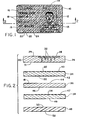
- Figure 1 is a front view showing the composite image of the engraved identification card in accordance with the present invention;
- Figure 2 is an exaggerated exploded cross- sectional side plan view of an engraved identification such as that shown in Figure 1.
- Referring initially to Figure 1, an engraved
identification card 10 has an engravedregion 12 which containsidentification images 13, such as the user's picture and signature, and possibly a non-engraved region which may provide other information such as acompany name 14, the user'sname 16, and other desiredidentification information 18. Background patterns, such asvertical cross-hatching 20 anddiagonal cross-hatching 22, appear over theentire surface 15 of thecard 10 in repeated patterns to form what appears as a composite pattern. Additionally, other patterns, such as the repeating "ABC Co."pattern 24, can be placed as an additional background pattern on the card. - Referring now to Figure 2, a
composite top 26 comprises an opaque top layer or insetregion 28 in afirst surface 29 of atranslucent bottom layer 30. Thetranslucent bottom layer 30 also has asecond surface 31, directly opposite thefirst surface 29. Engravedscores 32 extend through thetop layer 28 into thebottom layer 30 to form the engravedimages 13 shown in Figure 1. Thescores 32 are engraved into thecomposite top 26 at varying depths so that the greater the depth of thescore 32, the moreopaque top ply 28 will be removed and hence, the more bottomtranslucent ply 30 will be exposed. As the depth of thescores 32 decrease, a greater amount of thetop ply 28 remains, thus forming light and dark regions which, when viewed as a composite, forms the desired image. The maximum depth of the scores is only very slightly less than the thickness of the top andbottom layers bottom surface 31 of thebottom layer 30. - A first
translucent layer 34 lies directly beneath the engravedbottom layer 30 and in close proximity to the engraved scores. A secondtranslucent layer 36 is positioned beneath thefirst layer 34 and a thirdtranslucent layer 38 is affixed beneath thesecond layer 36. Thefirst layer 34 has atop surface 40 and abottom surface 42, thetop surface 40 being affixed to thesecond surface 31 of thebottom layer 30. On thetop surface 40 andbottom surface 42, thepatterns pattern 20 on thetop surface 40 may be the vertical line pattern and the imprintedpattern 22 on thebottom surface 42 may be the diagonal pattern. The patterns which are imprinted upon the firstplanar layer 34 can be made out of standard printer's ink or can alternatively be imprinted with an ink, such as ultraviolet ink, which prevents the patterns from being reproduced by photochemical or photocopying means. - Of course, the
patterns translucent layer 34 need not be imprinted on both itssurfaces pattern 20 imprinted at least on thetop surface 40 since this first layer is placed directly beneath the engraved scores and would be the first layer scraped off in any attempt to remove the engravedregion 12 from thecard 10. - The second
translucent layer 36, having atop surface 44 and abottom surface 46 is located directly beneath thefirst layer 34. Thetop surface 44 is affixed to thebottom surface 42 of thefirst layer 34. Printed information such as the user'sname 16 and thecompany name 14, along with the other identication information 18 (as shown in Figure 1) is placed on thetop surface 44 andbottom surface 46. Of course, if the letters or numerals are imprinted on thebottom surface 46, the digits would have to be imprinted as the mirror image of the numerals or letters desired to be observed. Again, the ink which can be used on this layer can be conventional printer's ink or can be a nonreproducable ink such as ultraviolet ink. - A third
translucent layer 38 having atop surface 47 and abottom surface 49 is affixed to thebottom surface 46 of thesecond ply 36. Another pattern, such as a repeatingholographic image 24, may be imprinted on either or both of thesurfaces third layer 38 can be any ornamental or identification image desired. The particular surface orsurfaces patterns layer - In another embodiment of the invention, an
opaque layer 48 having atop surface 50 and abottom surface 52 can be affixed beneath themultiple layers opaque layer 48 can further have written information, designs or patterns imprinted on thetop surface 50 to enhance the composite image of the card. It will be appreciated that the present invention can have a multiplicity of different arrangements and combinations of translucent layers. The arrangements can differ in regard to the number of layers used, the actual information which is printed on the surfaces of the layers, and the order in which the respective layers can be arranged. Such different arrangements can be implemented without deviating from the spirit and scope of the present invention. - The translucent layers of the present invention may be made of any suitable material such as polyvinyl chloride (PVC). The top
opaque ply 28 can be made from a plastic, ink or other suitable opaque material, while the bottomtranslucent layer 30 may be polyvinyl chloride. The thickness of thetop layer 28 andbottom layer 30 is such as to have thescores 32 of maximum depth extend down towards thesecond surface 31 of the bottomtranslucent ply 30 as far as possible in order to have the translucentplanar layers scores 32 will be so close to the top planar layers that the person altering the card would be likely to damage one or more of the imprinted surfaces of the translucent layers. - The translucent
planar layers bottom layer 30 since it is desirable to have as many layers scraped off the card when one attempts to scrape off the engravedregion 12. It is preferred, therefore, that the translucent layers be as thin as one mil or less. - The
top layer 28 and thebottom layer 30 can be applied to and made to adhere to each other by a suitable colorless transparent adhesive such as PVC adhesive which is well known in the art, or it could be heat bonded or fused together using other material bonding techniques well known in the art. Such bonding is done after the surface of the layers have been imprinted and only using a bonding method or structure which will not alter the imprinted image in an adverse way. Similarly, the other transparent planar layers can be bonded together and to theopaque layer 48 by using the same well known techniques of the art. - Prior to bonding the translucent layers together, the
surfaces planar layer 38 using known holographic techniques in the art. - In using the engraved identification card, it is desirable to check the background patterns which appear throughout the card in order to determine whether the engraved portion has been tampered with. This can be done by placing the identification card against a contrasting background which will show the background patterns more easily. Alternatively, the card can be held up to a light to see if the pattern is continuous behind the engraved region of the card. Once a pattern appears to have been broken, erased, or does not align properly behind the engraved region of the card, the person should then know that the card has been tampered with. As used herein, "translucent" includes "transparent".
- Although the embodiment disclosed here is representative of the present invention, the elements comprising the invention can assume a wide variety of shapes and forms, some of which can be quite different from the embodiment disclosed herein. Also, a multiplicity of different arrangements can be made using the translucent planar layers, while still remaining within the scope and spirit of the present invention.
Claims (20)
1. An engraved identification card comprising:
a translucent bottom layer having a first surface and a second surface;
an opaque top layer disposed to cover at least a portion of the first surface of the bottom layer, wherein a plurality of engraved scores extend through the top layer into the bottom layer to form an engraved image;
at least one translucent first layer affixed to the second surface of the bottom layer, the first layer having a top surface and bottom surface; and
printed matter imprinted on at least one of the top and bottom surfaces of the first layer.
2. An engraved identification card as defined in claim 1 wherein the printed matter is imprinted on both the top and bottom surfaces of the first layer.
3. An engraved identification card as defined in claim 1 or 2 wherein the printed matter on at least one of the top and bottom surfaces comprises a bendet pattern.
4. An engraved identification card as defined in claim 1 or 2 wherein the printed matter on at least one of the top and bottom surfaces comprises a holographic pattern.
5. An engraved identification card as defined in claim 1 or 2 wherein the printed matter on at least one of the top and bottom surfaces comprises printed information.
6. An engraved identification card as defined in claim 1 or 2 wherein the printed matter is imprinted with ink which is incapable of being photographed by photochemical means.
7. An engraved identification card as defined in claim 1 or 2 wherein the printed matter is imprinted with ink which is incapable of being photocopied by photocopying means.
8. An engraved identification card as defined in any preceding claim further comprising an opaque layer affixed to the bottom surface of the first planar layer.
9. An engraved identification card as defined in any preceding claim wherein at least some of the engraved scores extend through the top layer into the bottom layer in close proximity to the second surface of the bottom layer.
10. An engraved identification card as defined in any preceding claim wherein the translucent first layer has a thickness less than about 1 mil.
11. An engraved identification card as defined in any preceding claim further comprising a translucent second layer having a top surface and a bottom surface, the top surface of the second layer being affixed to the bottom surface of the first layer, printed matter being imprinted on at least one of the top and bottom surfaces of the second layer.
12. An engraved identification card as defined in claim 11 wherein the printed matter on at least one of the top and bottom surfaces of the second layer comprises a bendet pattern.
13. An engraved identification card as defined in claim 11 wherein the printed matter on at least one of the top and bottom surfaces of the second layer comprises a holographic pattern.
14. An engraved identification card as defined in claim 11 wherein the printed matter on at least one of the top and bottom surfaces of the second layer comprises printed information.
15. An engraved identification card as defined in any of claims 11 to 14 further comprising an opaque layer affixed to the bottom surface of the second planar layer.
16. An engraved identification card comprising:
a translucent bottom layer having a first surface and a second surface;
an opaque top layer disposed to cover at least a portion of the first surface of the bottom layer, wherein a plurality of engraved scores extend through the top layer into the bottom layer to form an engraved image;
a plurality of translucent layers joined together in a stacked configuration, the layers being affixed to the second surface of the bottom layer, each layer having a top surface and a bottom surface; and
/ printed matter disposed on at least one of the plurality of top and bottom surfaces of the translucent layers.
17. An engraved identification card as defined in claim 16 further comprising an opaque layer affixed to the bottom surface of the translucent layers.
18. An engraved identification card as defined in claim 16 or 17 wherein the plurality of translucent layers comprises:
a translucent first layer having a bendet pattern printed upon the top and bottom surface;
a translucent second layer having a bendet pattern printed upon the top and bottom surface;
and a translucent third layer having printed words upon the top surface.
19. An engraved identification card as defined in any of claims 16 to 18 wherein at least some of the engraved scores extend through the top layer into the bottom layer in close proximity to the second surface of the bottom layer.
20. An engraved identification card as defined in any of claims 16 to 19 wherein each translucent layer has a thickness less than about 1 mil.
Applications Claiming Priority (2)
| Application Number | Priority Date | Filing Date | Title |
|---|---|---|---|
| US56109883A | 1983-12-13 | 1983-12-13 | |
| US561098 | 1983-12-13 |
Publications (2)
| Publication Number | Publication Date |
|---|---|
| EP0145473A2 true EP0145473A2 (en) | 1985-06-19 |
| EP0145473A3 EP0145473A3 (en) | 1985-07-24 |
Family
ID=24240623
Family Applications (1)
| Application Number | Title | Priority Date | Filing Date |
|---|---|---|---|
| EP84308565A Withdrawn EP0145473A3 (en) | 1983-12-13 | 1984-12-10 | Engraved image identification card |
Country Status (4)
| Country | Link |
|---|---|
| EP (1) | EP0145473A3 (en) |
| JP (1) | JPS60199697A (en) |
| KR (1) | KR850004552A (en) |
| IL (1) | IL73732A0 (en) |
Cited By (8)
| Publication number | Priority date | Publication date | Assignee | Title |
|---|---|---|---|---|
| EP0170832A1 (en) | 1984-06-20 | 1986-02-12 | Leonhard Kurz Gmbh & Co. | Blocking foil in particular hot-blocking foil with a writing surface |
| FR2624435A1 (en) * | 1987-12-14 | 1989-06-16 | Oberthur Francois | OFFICIAL DOCUMENT FOR PERSONAL USE, METHOD FOR MANUFACTURING THE SAME, AND DEVICE FOR IMPLEMENTING THE METHOD |
| EP0166326B1 (en) * | 1984-06-20 | 1989-08-30 | Kurz Gmbh & Co. Leonhard | Blocking foil, in particular hot-blocking foil with a magnetic layer |
| EP0171540B1 (en) * | 1984-06-20 | 1989-08-30 | Kurz Gmbh & Co. Leonhard | Blocking foil, in particular hot-blocking foil with a magnetic layer |
| WO1992022039A1 (en) * | 1991-06-05 | 1992-12-10 | Mikoh Pty. Ltd. | Optical memories incorporating diffraction gratings |
| EP0518363A1 (en) * | 1991-06-14 | 1992-12-16 | Epc Technology Co., Ltd. | Engraved sheet structure |
| EP0756945A1 (en) * | 1995-07-31 | 1997-02-05 | National Bank Of Belgium | Colour copy protection of security documents |
| WO2016128305A1 (en) * | 2015-02-09 | 2016-08-18 | Bundesdruckerei Gmbh | Value or security product and method for the production thereof with decentralised individualisation |
Families Citing this family (1)
| Publication number | Priority date | Publication date | Assignee | Title |
|---|---|---|---|---|
| JPH0518779Y2 (en) * | 1986-03-20 | 1993-05-18 |
Citations (4)
| Publication number | Priority date | Publication date | Assignee | Title |
|---|---|---|---|---|
| US3897964A (en) * | 1971-12-08 | 1975-08-05 | Dainippon Printing Co Ltd | Identification cards and method for making the same |
| FR2366658A1 (en) * | 1976-09-29 | 1978-04-28 | Transac Dev Transact Automat | Identity card including photograph - with watermark beneath latter and visible through clear areas of photograph |
| EP0011684A2 (en) * | 1978-09-06 | 1980-06-11 | Aktiengesellschaft Hoechst | Identification card |
| GB2092952A (en) * | 1981-02-18 | 1982-08-25 | Silver David Selwyn | Identification method |
-
1984
- 1984-12-05 IL IL73732A patent/IL73732A0/en unknown
- 1984-12-10 EP EP84308565A patent/EP0145473A3/en not_active Withdrawn
- 1984-12-10 KR KR1019840007798A patent/KR850004552A/en not_active Application Discontinuation
- 1984-12-13 JP JP59263715A patent/JPS60199697A/en active Pending
Patent Citations (4)
| Publication number | Priority date | Publication date | Assignee | Title |
|---|---|---|---|---|
| US3897964A (en) * | 1971-12-08 | 1975-08-05 | Dainippon Printing Co Ltd | Identification cards and method for making the same |
| FR2366658A1 (en) * | 1976-09-29 | 1978-04-28 | Transac Dev Transact Automat | Identity card including photograph - with watermark beneath latter and visible through clear areas of photograph |
| EP0011684A2 (en) * | 1978-09-06 | 1980-06-11 | Aktiengesellschaft Hoechst | Identification card |
| GB2092952A (en) * | 1981-02-18 | 1982-08-25 | Silver David Selwyn | Identification method |
Cited By (12)
| Publication number | Priority date | Publication date | Assignee | Title |
|---|---|---|---|---|
| EP0170832A1 (en) | 1984-06-20 | 1986-02-12 | Leonhard Kurz Gmbh & Co. | Blocking foil in particular hot-blocking foil with a writing surface |
| EP0166326B1 (en) * | 1984-06-20 | 1989-08-30 | Kurz Gmbh & Co. Leonhard | Blocking foil, in particular hot-blocking foil with a magnetic layer |
| EP0171540B1 (en) * | 1984-06-20 | 1989-08-30 | Kurz Gmbh & Co. Leonhard | Blocking foil, in particular hot-blocking foil with a magnetic layer |
| FR2624435A1 (en) * | 1987-12-14 | 1989-06-16 | Oberthur Francois | OFFICIAL DOCUMENT FOR PERSONAL USE, METHOD FOR MANUFACTURING THE SAME, AND DEVICE FOR IMPLEMENTING THE METHOD |
| EP0322331A1 (en) * | 1987-12-14 | 1989-06-28 | Francois-Charles Oberthur Fiduciaire | Official document for personal use, and method and device for manufacturing it |
| WO1992022039A1 (en) * | 1991-06-05 | 1992-12-10 | Mikoh Pty. Ltd. | Optical memories incorporating diffraction gratings |
| US5461239A (en) * | 1991-06-05 | 1995-10-24 | Mikoh Pty Ltd | Method and apparatus for coding and reading information in diffraction gratings using the divergence of diffracted light beams |
| EP0518363A1 (en) * | 1991-06-14 | 1992-12-16 | Epc Technology Co., Ltd. | Engraved sheet structure |
| EP0756945A1 (en) * | 1995-07-31 | 1997-02-05 | National Bank Of Belgium | Colour copy protection of security documents |
| WO2016128305A1 (en) * | 2015-02-09 | 2016-08-18 | Bundesdruckerei Gmbh | Value or security product and method for the production thereof with decentralised individualisation |
| CN107206830A (en) * | 2015-02-09 | 2017-09-26 | 联邦印刷有限公司 | Valuable or safety product and for using non-central individual character manufacturing is valuable or method of safety product |
| CN107206830B (en) * | 2015-02-09 | 2019-10-18 | 联邦印刷有限公司 | Valuable or safety product and for using non-central individual character manufacturing is valuable or the method for safety product |
Also Published As
| Publication number | Publication date |
|---|---|
| JPS60199697A (en) | 1985-10-09 |
| IL73732A0 (en) | 1985-03-31 |
| EP0145473A3 (en) | 1985-07-24 |
| KR850004552A (en) | 1985-07-25 |
Similar Documents
| Publication | Publication Date | Title |
|---|---|---|
| US4735670A (en) | Method of producing an identification card | |
| US6505779B1 (en) | Security document with security marking formed of transparent windows | |
| US4313984A (en) | Laminated identity card having separation-resistant laminae and method of manufacturing same | |
| US3755935A (en) | Double photograph identification card | |
| US20060197337A1 (en) | Identification document with lenticular watermark | |
| US4223918A (en) | Color coded credit card | |
| JPS62103682A (en) | Id card having visible recognition mark and manufacture thereof | |
| EA006422B1 (en) | Identity card and travel document | |
| EP0145473A2 (en) | Engraved image identification card | |
| US3621589A (en) | Indicia coding and decoding apparatus | |
| RU2322359C2 (en) | Information carrier and method for manufacturing it | |
| EP3634774B1 (en) | Forge-proof document | |
| US3967400A (en) | Identification card | |
| EP0145474A2 (en) | Protectively covered identification card | |
| EP0113228A2 (en) | Improvements relating to security cards | |
| JP2005520711A (en) | Means to prevent counterfeiting of banknotes and cards | |
| JPH11321166A (en) | Id card, and its manufacture | |
| KR100587621B1 (en) | A security paper with optical variable complex latent image and method of preparing thereof | |
| JPS5911538A (en) | Magnetic card | |
| AU1150983A (en) | Engraved image identification card | |
| JPS622141Y2 (en) | ||
| JPH0139578Y2 (en) | ||
| JPH0781281A (en) | Information medium | |
| JPS6210124Y2 (en) | ||
| GB2229963A (en) | Security card |
Legal Events
| Date | Code | Title | Description |
|---|---|---|---|
| PUAI | Public reference made under article 153(3) epc to a published international application that has entered the european phase |
Free format text: ORIGINAL CODE: 0009012 |
|
| PUAL | Search report despatched |
Free format text: ORIGINAL CODE: 0009013 |
|
| AK | Designated contracting states |
Designated state(s): AT BE DE FR GB NL SE |
|
| AK | Designated contracting states |
Designated state(s): AT BE DE FR GB NL SE |
|
| RIN1 | Information on inventor provided before grant (corrected) |
Inventor name: PHELPS, BARRY C. |
|
| STAA | Information on the status of an ep patent application or granted ep patent |
Free format text: STATUS: THE APPLICATION IS DEEMED TO BE WITHDRAWN |
|
| 18D | Application deemed to be withdrawn |
Effective date: 19860325 |
|
| RIN1 | Information on inventor provided before grant (corrected) |
Inventor name: PHELPS, BARRY C. |