EP0143213A1 - Automatic device for ventilating under pressure the ink supply reservoir of a printer - Google Patents
Automatic device for ventilating under pressure the ink supply reservoir of a printer Download PDFInfo
- Publication number
- EP0143213A1 EP0143213A1 EP84110463A EP84110463A EP0143213A1 EP 0143213 A1 EP0143213 A1 EP 0143213A1 EP 84110463 A EP84110463 A EP 84110463A EP 84110463 A EP84110463 A EP 84110463A EP 0143213 A1 EP0143213 A1 EP 0143213A1
- Authority
- EP
- European Patent Office
- Prior art keywords
- ink
- ink drop
- sensor
- nozzle
- tank
- Prior art date
- Legal status (The legal status is an assumption and is not a legal conclusion. Google has not performed a legal analysis and makes no representation as to the accuracy of the status listed.)
- Granted
Links
Images
Classifications
-
- B—PERFORMING OPERATIONS; TRANSPORTING
- B41—PRINTING; LINING MACHINES; TYPEWRITERS; STAMPS
- B41J—TYPEWRITERS; SELECTIVE PRINTING MECHANISMS, i.e. MECHANISMS PRINTING OTHERWISE THAN FROM A FORME; CORRECTION OF TYPOGRAPHICAL ERRORS
- B41J27/00—Inking apparatus
-
- B—PERFORMING OPERATIONS; TRANSPORTING
- B41—PRINTING; LINING MACHINES; TYPEWRITERS; STAMPS
- B41J—TYPEWRITERS; SELECTIVE PRINTING MECHANISMS, i.e. MECHANISMS PRINTING OTHERWISE THAN FROM A FORME; CORRECTION OF TYPOGRAPHICAL ERRORS
- B41J2/00—Typewriters or selective printing mechanisms characterised by the printing or marking process for which they are designed
- B41J2/005—Typewriters or selective printing mechanisms characterised by the printing or marking process for which they are designed characterised by bringing liquid or particles selectively into contact with a printing material
- B41J2/01—Ink jet
- B41J2/21—Ink jet for multi-colour printing
- B41J2/2103—Features not dealing with the colouring process per se, e.g. construction of printers or heads, driving circuit adaptations
Definitions
- the invention relates to a device for automatic, error-controlled pressure ventilation of an ink supply tank traveling with a movable piezo nozzle print head of an ink printer.
- registration devices are used to monitor process variables. They are used to continuously record measured quantities.
- ink jet method has recently been used for the registration of measured variables.
- Individual drops of TiLI are ejected from a nozzle with the aid of a piezoelectric body, which - controlled accordingly - impulsively narrows an ink space behind the nozzle.
- the nozzles are located a short distance from the writing paper.
- the writing device is combined with the ink supply tank to form a printhead.
- a plurality of nozzles which inject differently colored inks can also be combined to form a print head.
- the ink is typically under a slight vacuum. Ink is sucked into the ink supply tank by means of the piezoelectric body, by means of a re-expansion of the ink space following the constriction which causes the spraying.
- Ejection of ink droplets is disturbed when gas bubbles enter the feed channel to the ink nozzle This can happen by the meniscus of the ink liquid receding into the ink space behind the nozzle, by cavitation processes in the event of rapid changes in pressure or by the separation of gases dissolved in the ink.
- the ink tank In order to remove such gas bubbles from the supply line to the nozzle, it is known (DE-PS 27 04 735) to design the ink tank as a flexible bag which is stored in a tub. A mechanical pressure is exerted on the ink bag in order to increase the ink pressure, which should cause the bubbles to be expelled from the nozzle feed. This can be done by the finger pressure of a person watching the typeface for errors.
- the housing of a recording device In order to access the aforementioned ink bag, the housing of a recording device must be opened and the printer carriage must be stopped. Apart from the fact that during this time a recording, albeit faulty, is interrupted in whole or in part, the monitoring of recording devices by people is very uneconomical. It is better to give the recording devices a high level of operational reliability.
- the invention was based on the object of a device for automatic monitoring and restoration. dpr create recording quality, as far as this is affected by clogging of the nozzles and their feed lines by gas bubbles.
- the rigid container of the ink supply tank which is known per se from the documents of DE-GM 80 24 472, enables pneumatic pressure to be exerted on the flexible membrane, which separates the ink space of the ink supply tank from the air space.
- the pressurized air is fed through the flexible hose that follows the movements of the Printer carriage can follow without resistance.
- the proper ejection of ink drops from the nozzle or nozzles is monitored by an ink drop sensor, which in turn emits a signal if a nozzle fails.
- This signal controls the switching solenoid valve such that it switches from a connection of the air space with the free atmosphere to the connection of the air space via the flexible hose to a compressed air container.
- the facility works completely automatically without the intervention of personnel.
- the ink drop sensor is expediently arranged at a point on the print head path that can be approached by the print head.
- the ink drop sensor can consist of a light sensor for detecting the reflected or transmitted light intensity emanating from a spot of a recording paper hit by an ink drop.
- the ink drop sensor consists of a charge sensor for an electrical charge communicated to the individual ink droplets when they emerge from the nozzle.
- a thermistor is used as the ink drop sensor, which is hit by individual ink drops.
- an ink drop sensor which consists of a light barrier that detects the drop path from the nozzle to the recording paper.
- the weakening of light which causes an ink droplet to fly through this path, is converted into an electrical signal by the light barrier, which controls the solenoid valve accordingly.
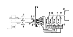
- a piezo nozzle print head 1 is arranged so as to be movable relative to a registration paper sheet or strip 2.
- a light sensor 3 is arranged on the side of the paper sheet 2 opposite the print head.
- the light sensor consists of a light emission diode 4, which illuminates a precisely defined point on the paper with a condensed light beam via a condenser lens 5.
- the light reflected from this point is converted into a voltage value via a further condenser lens 6 and a light receiver 7 and fed to an evaluation device via an amplifier 8.
- the light emission diode 4 is controlled programmably via an additional amplifier 9 with an electrical signal.
- the electrical output signal of the amplifier 8 is shown symbolically in relation to the input signal of the amplifier 9.
- the piezo nozzle print head 1 has nozzles for four different colors. These colors can be recognized by different pulse heights of the output signal of the amplifier 8.
- the piezo nozzle print head 1 is supplied with the differently colored inks by ink supply tanks 10 ... 13 traveling with the print head.
- the individual ink supply tank consists of a bulge-resistant container which is divided by a flexible membrane 14 into an ink and an air space.
- the air spaces of the ink supply tanks 10 ... 13 can be connected to a compressed air tank 23 via flexible hoses 15 ... 18 and controllable solenoid valves 19 ... 22. In their normal position, the solenoid valves connect the air spaces of the ink supply tanks with the free atmosphere.
- the piezo nozzle print head is moved to the place of the ink drop sensor. This is done automatically by a program entered into a control device.
- the droplet sensor can be compared to each individual nozzle using the same program.
- the control device mentioned which is not shown in the figure, controls the light-emitting diode 4 via the amplifier 9 after the droplet ejection signal.
- an evaluation device for the output signal of the amplifier 8 can determine whether an ink droplet has reached the illuminated position or not, and via a magnetic valve driver, also not shown, the corresponding nozzle by pressurizing the associated ink supply tank with ink under increased pressure act upon. Any gas bubbles are expelled.
Abstract
Description
Die Erfindung betrifft eine Einrichtung zur selbsttätigen, fehlergesteuerten Druckbelüftung eines mit einem beweglichen Piezo-Düsendruckkopf eines Tintendruckers mitfahrenden Tintenvorratstanks.The invention relates to a device for automatic, error-controlled pressure ventilation of an ink supply tank traveling with a movable piezo nozzle print head of an ink printer.
Für die Überwachung von Prozeßgrößen werden in vielen Anwendungsfällen Registriergeräte eingesetzt. Sie dienen dazu, eine kontinuierliche Aufzeichnung von Meßgrößen durchzuführen.In many applications, registration devices are used to monitor process variables. They are used to continuously record measured quantities.
Neben vielen anderen Verfahren wird in jüngerer Zeit auch ein sogenanntes Ink-Jet-Verfahren für die Registrierung von Meßgrößen eingesetzt. Dabei werden einzelne TiLILeutropfen aus einer Düse mit Hilfe eines piezoelektrischen Körpers ausgestoßen, der - entsprechend angesteuert - einen hinter der Düse befindlichen Tintenraum impulsartig verengt. Die Düsen befinden sich in einem geringen Abstand vom Schreibpapier. Die Schreibeinrichtung ist zusammen mit dem Tintenvorratstank zu einem Druckkopf zusammengefaßt. Es können auch mehrere Düsen, die verschiedenfarbige Tinten ausspritzen, zu einem Druckkopf vereinigt sein. Damit zwischen einzelnen Ausstoßvorgängen von Tintentröpfchen aus der Düse keine Tinte austreten kann, steht die Tinte normalerweise unter einem geringen Unterdruck. In den mit Hilfe des piezoelektrischen Körpers variierbaren Tintenraum wird Tinte aus dem Tintenvorratstank durch eine auf die das Ausspritzen bewirkende Verengung folgende Wiederaufweitung des Tintenraumes nachgesaugt.In addition to many other methods, a so-called ink jet method has recently been used for the registration of measured variables. Individual drops of TiLI are ejected from a nozzle with the aid of a piezoelectric body, which - controlled accordingly - impulsively narrows an ink space behind the nozzle. The nozzles are located a short distance from the writing paper. The writing device is combined with the ink supply tank to form a printhead. A plurality of nozzles which inject differently colored inks can also be combined to form a print head. To prevent ink from escaping from the nozzle between individual ejections of ink droplets, the ink is typically under a slight vacuum. Ink is sucked into the ink supply tank by means of the piezoelectric body, by means of a re-expansion of the ink space following the constriction which causes the spraying.
Das Ausstoßen von Tintentröpfchen wird gestört, wenn Gasblasen in den Zuführungskanal zu der Tintendüse eindringen. Das kann geschehen durch Zurückweichen des Meniskus der Tintenflüssigkeit in den Tintenraum hinter der Düse, durch Kavitationsvorgänge bei schnellen Druckänderungen oder auch durch Abscheiden von in der Tinte gelösten Gasen.Ejection of ink droplets is disturbed when gas bubbles enter the feed channel to the ink nozzle This can happen by the meniscus of the ink liquid receding into the ink space behind the nozzle, by cavitation processes in the event of rapid changes in pressure or by the separation of gases dissolved in the ink.
Um derartige Gasblasen aus der Zuführungsleitung zur Düse zu entfernen, ist es bekannt (DE-PS 27 04 735), den Tintentank als flexiblen Beutel auszubilden, der in einer Wanne gelagert ist. Zur Tintendruckerhöhung, die ein Austreiben der Blasen aus der Düsenzuführung herbeiführen soll, wird auf den Tintenbeutel ein mechanischer Druck ausgeübt. Dies kann durch einen Fingerdruck einer das Schriftbild auf Fehler beobachtenden Person geschehen.In order to remove such gas bubbles from the supply line to the nozzle, it is known (DE-PS 27 04 735) to design the ink tank as a flexible bag which is stored in a tub. A mechanical pressure is exerted on the ink bag in order to increase the ink pressure, which should cause the bubbles to be expelled from the nozzle feed. This can be done by the finger pressure of a person watching the typeface for errors.
Um an den vorerwähnten Tintenbeutel zu gelangen, muß dabei das Gehäuse eines Registriergerätes geöffnet und der Druckerwagen angehalten werden. Abgesehen davon, daß in dieser Zeit eine, wenn auch fehlerhafte Aufzeichnung ganz oder teilweise unterbrochen wird, ist die Überwachung von Registriergeräten durch Personen sehr unwirtschaftlich. Besser ist es, den Aufzeichnungsgeräten eine hohe Betriebssicherheit zu verleihen.In order to access the aforementioned ink bag, the housing of a recording device must be opened and the printer carriage must be stopped. Apart from the fact that during this time a recording, albeit faulty, is interrupted in whole or in part, the monitoring of recording devices by people is very uneconomical. It is better to give the recording devices a high level of operational reliability.
Der Erfindung lag die Aufgabe zugrunde, eine Einrichtung zur automatischen Überwachung und Wiederherstellung. dpr Aufzeichnungsqualität zu schaffen, soweit diese durch Verstopfung der Düsen und ihrer Zuleitungen durch Gasblasen beeinträchtigt wird.The invention was based on the object of a device for automatic monitoring and restoration. dpr create recording quality, as far as this is affected by clogging of the nozzles and their feed lines by gas bubbles.
Diese Aufgabe wird gemäß der Erfindung durch die Kombination der kennzeichnenden Merkmale des Anspruchs 1 gelöst.This object is achieved according to the invention by the combination of the characterizing features of claim 1.
Der steife Behälter des Tintenvorratstanks, der an sich aus den Unterlagen des DE-GM 80 24 472 bekannt ist, ermöglicht eine pneumatische Druckausübung auf die flexible Membran, die den Tintenraum des Tintenvorratstanks vom Luftraum trennt. Die unter Druck stehende Luft wird über den flexiblen Schlauch zugeführt, der den Bewegungen des Druckerwagens widerstandslos folgen kann. Das ordnungsgemäße Ausstoßen von Tintentropfen aus der Düse oder den Düsen wird von einem Tintentropfensensor überwacht, der seinerseits bei Ausfall einer Düse ein Signal abgibt. Dieses Signal steuert das Umschaltmagnetventil derart, daß es von einer Verbindung des Luftraumes mit der freien Atmosphäre auf den Anschluß des Luftraumes über den flexiblen Schlauch an einen Druckluftbehälter umschaltet. Die Einrichtung arbeitet also vollkommen selbsttätig ohne Einwirkung von Personal.The rigid container of the ink supply tank, which is known per se from the documents of DE-GM 80 24 472, enables pneumatic pressure to be exerted on the flexible membrane, which separates the ink space of the ink supply tank from the air space. The pressurized air is fed through the flexible hose that follows the movements of the Printer carriage can follow without resistance. The proper ejection of ink drops from the nozzle or nozzles is monitored by an ink drop sensor, which in turn emits a signal if a nozzle fails. This signal controls the switching solenoid valve such that it switches from a connection of the air space with the free atmosphere to the connection of the air space via the flexible hose to a compressed air container. The facility works completely automatically without the intervention of personnel.
Der Tintentropfensensor ist zweckmäßig an einer vom Druckkopf anfahrbaren Stelle des Druckkopfweges angeordnet.The ink drop sensor is expediently arranged at a point on the print head path that can be approached by the print head.
Der Tintentropfensensor kann in einer bevorzugten Ausführungsform der Erfindung aus einem Lichtsensor zur Erfassung der von einem durch einen Tintentropfen getroffenen Fleck eines Aufzeichnungspapiers ausgehenden reflektierten oder transmittierten Lichtstärke bestehen.In a preferred embodiment of the invention, the ink drop sensor can consist of a light sensor for detecting the reflected or transmitted light intensity emanating from a spot of a recording paper hit by an ink drop.
Bei einem anderen Ausführungsbeispiel besteht der Tintentropfensensor aus einem Ladungssensor für eine den einzelnen Tintentröpfchen beim Austritt aus der Düse mitgeteilte elektrische Ladung.In another embodiment, the ink drop sensor consists of a charge sensor for an electrical charge communicated to the individual ink droplets when they emerge from the nozzle.
Bei einem weiteren Ausführungsbeispiel wird als Tintentropfensensor ein Heißleiter benutzt, der von einzelnen Tintentropfen getroffen wird.In a further exemplary embodiment, a thermistor is used as the ink drop sensor, which is hit by individual ink drops.
Schließlich ist auch ein Tintentropfensensor möglich, der aus einer Lichtschranke besteht, die den Tropfenweg von der Düse bis zum Aufzeichnungspapier erfaßt. Die Lichtschwächung, die ein diesen Weg durchfliegendes Tintentröpfchen bewirkt, wird von der Lichtschranke in ein elektrisches Signal umgeformt, die das Magnetventil entsprechend steuert.Finally, an ink drop sensor is also possible, which consists of a light barrier that detects the drop path from the nozzle to the recording paper. The weakening of light, which causes an ink droplet to fly through this path, is converted into an electrical signal by the light barrier, which controls the solenoid valve accordingly.
Die Erfindung wird anhand einer Figur, die das bevorzugte Ausführungsbeispiel in schematischer Weise darstellt, erläutert.The invention is explained on the basis of a figure which represents the preferred exemplary embodiment in a schematic manner.
Ein Piezo-Düsendruckkopf 1 ist relativ zu einem Registrierpapierblatt oder -streifen 2 beweglich angeordnete An einer Stelle, die vom Druckkopf 1 anfahrbar ist, ist auf der dem Druckkopf gegenüberliegenden Seite des Papierblattes 2 ein Lichtsensor 3 angeordnet. Der Lichtsensor besteht aus einer Lichtemissionsdiode 4, die über eine Kondensorlinse 5 mit einem gebündelten Lichtstrahl eine genau definierte Stelle auf dem Papier anleuchtet. Das von dieser Stelle reflektierte Licht wird über eine weitere Kondensorlinse 6 und einen Lichtempfänger 7 in einen Spannungswert umgewandelt und über einen Verstärker 8 einer Auswerteeinrichtung zugeführt. Die Lichtemissionsdiode 4 wird über einen weiteren Verstärker 9 programmierbar mit einem elektrischen Signal angesteuert. Das elektrische Ausgangssignal des Verstärkers 8 ist symbolisch gegenüber dem Eingangssignal des Verstärkers 9 dargestellt. Die Amplitude des impulsartigen Signals ist am höchsten, wenn der beleuchtete Punkt weiß ist. Der Piezo-Düsendruckkopf 1 weist Düsen für vier verschiedene Farben auf. Diese Farben sind an verschiedenen Impulshöhen des Ausgangssignals des Verstärkers 8 erkennbar. Der Piezo-Düsendruckkopf 1 wird mit den verschiedenfarbigen Tinten durch mit dem Druckkopf mitfahrende Tintenvorratstanks 10 ... 13 versorgt. Der einzelne Tintenvorratstank besteht aus einem beulsteifen Behälter, der durch eine flexible Membran 14 in einen Tinten- und einen Luftraum unterteilt ist. Die Lufträume der Tintenvorratstanks 10 ... 13 sind über flexible Schläuche 15 ... 18 und steuerbare Magnetventile 19 ... 22 an einen Druckluftbehälter 23 anschließbar. In ihrer Normalstellung verbinden die Magnetventile die Lufträume der Tintenvorratstanks mit der freien Atmosphäre.A piezo nozzle print head 1 is arranged so as to be movable relative to a registration paper sheet or strip 2. At a point which can be approached by the print head 1, a light sensor 3 is arranged on the side of the paper sheet 2 opposite the print head. The light sensor consists of a light emission diode 4, which illuminates a precisely defined point on the paper with a condensed light beam via a condenser lens 5. The light reflected from this point is converted into a voltage value via a further condenser lens 6 and a light receiver 7 and fed to an evaluation device via an amplifier 8. The light emission diode 4 is controlled programmably via an additional amplifier 9 with an electrical signal. The electrical output signal of the amplifier 8 is shown symbolically in relation to the input signal of the amplifier 9. The amplitude of the pulse-like signal is highest when the illuminated spot is white. The piezo nozzle print head 1 has nozzles for four different colors. These colors can be recognized by different pulse heights of the output signal of the amplifier 8. The piezo nozzle print head 1 is supplied with the differently colored inks by
Zur Überprüfung der einzelnen Düsen wird der Piezo-Düsendruckkopf an die Stelle des Tintentropfensensors gefahren. Dies geschieht automatisch durch ein einer Steuereinrichtung eingegebenes Programm. Dem Tröpfchensensor kann durch das gleiche Programm jede einzelne Düse gegenübergestellt werden. Die erwähnte Steuereinrichtung, die in der Figur nicht dargestellt ist, steuert nach dem Ausstoßsignal für ein Tröpfchen die Lichtemissionsdiode 4 über den Verstärker 9 an. Entsprechend der Stärke des zurückgeworfenen Lichts kann eine Auswerteeinrichtung für das Ausgangssignal des Verstärkers 8 feststellen, ob ein Tintentröpfchen an die beleuchtete Stelle gelangt ist oder nicht, und über einen ebenfalls nicht dargestellten Magnetventiltreiber die entsprechende Düse durch Druckbelüftung des ihr zugeordneten Tintenvorratstanks mit Tinte unter erhöhtem Druck beaufschlagen. Eventuelle Gasblasen werden dabei ausgetrieben.To check the individual nozzles, the piezo nozzle print head is moved to the place of the ink drop sensor. This is done automatically by a program entered into a control device. The droplet sensor can be compared to each individual nozzle using the same program. The control device mentioned, which is not shown in the figure, controls the light-emitting diode 4 via the amplifier 9 after the droplet ejection signal. Depending on the strength of the reflected light, an evaluation device for the output signal of the amplifier 8 can determine whether an ink droplet has reached the illuminated position or not, and via a magnetic valve driver, also not shown, the corresponding nozzle by pressurizing the associated ink supply tank with ink under increased pressure act upon. Any gas bubbles are expelled.
In entsprechender Weise arbeiten auch die anderen, in den Unteransprüchen vorgeschlagenen Tintentropfensensoren.The other ink drop sensors proposed in the subclaims also operate in a corresponding manner.
Claims (6)
Applications Claiming Priority (2)
| Application Number | Priority Date | Filing Date | Title |
|---|---|---|---|
| DE3335663 | 1983-09-30 | ||
| DE19833335663 DE3335663A1 (en) | 1983-09-30 | 1983-09-30 | DEVICE FOR THE AUTOMATIC PRINT VENTILATION OF AN INK TANK IN AN INK PRINTER |
Publications (2)
| Publication Number | Publication Date |
|---|---|
| EP0143213A1 true EP0143213A1 (en) | 1985-06-05 |
| EP0143213B1 EP0143213B1 (en) | 1987-08-19 |
Family
ID=6210663
Family Applications (1)
| Application Number | Title | Priority Date | Filing Date |
|---|---|---|---|
| EP84110463A Expired EP0143213B1 (en) | 1983-09-30 | 1984-09-03 | Automatic device for ventilating under pressure the ink supply reservoir of a printer |
Country Status (2)
| Country | Link |
|---|---|
| EP (1) | EP0143213B1 (en) |
| DE (2) | DE3335663A1 (en) |
Cited By (5)
| Publication number | Priority date | Publication date | Assignee | Title |
|---|---|---|---|---|
| FR2601265A1 (en) * | 1986-05-28 | 1988-01-15 | Cherubin Grillo Victor | Microprocessor-controlled system for forming a picture by point-by-point polychrome printing on a plane or raised surface |
| WO1988004611A1 (en) * | 1986-12-22 | 1988-06-30 | Eastman Kodak Company | Pressure regulation system for multi-head ink jet printing apparatus |
| GB2203386B (en) * | 1987-04-03 | 1991-12-11 | Canon Kk | Ink cardtridge, and a liquid ejection recording apparatus provided with the ink cartridge. |
| EP0509687A2 (en) * | 1991-04-17 | 1992-10-21 | Hewlett-Packard Company | Priming apparatus and process for multi-color ink-jet pens |
| US5221936A (en) * | 1987-04-03 | 1993-06-22 | Canon Kabushiki Kaisha | Ink tank having a vent path opened and closed by a movable magnetic member |
Citations (4)
| Publication number | Priority date | Publication date | Assignee | Title |
|---|---|---|---|---|
| US4045770A (en) * | 1976-11-11 | 1977-08-30 | International Business Machines Corporation | Method and apparatus for adjusting the velocity of ink drops in an ink jet printer |
| US4217595A (en) * | 1978-04-27 | 1980-08-12 | Ricoh Company, Ltd. | Charging phase control device for ink jet recording device |
| US4323908A (en) * | 1980-08-01 | 1982-04-06 | International Business Machines Corp. | Resonant purging of drop-on-demand ink jet print heads |
| DE3244809A1 (en) * | 1981-12-09 | 1983-07-21 | Konishiroku Photo Industry Co., Ltd., Tokyo | Ink jet printer and ink jet print head for it |
-
1983
- 1983-09-30 DE DE19833335663 patent/DE3335663A1/en not_active Withdrawn
-
1984
- 1984-09-03 EP EP84110463A patent/EP0143213B1/en not_active Expired
- 1984-09-03 DE DE8484110463T patent/DE3465439D1/en not_active Expired
Patent Citations (4)
| Publication number | Priority date | Publication date | Assignee | Title |
|---|---|---|---|---|
| US4045770A (en) * | 1976-11-11 | 1977-08-30 | International Business Machines Corporation | Method and apparatus for adjusting the velocity of ink drops in an ink jet printer |
| US4217595A (en) * | 1978-04-27 | 1980-08-12 | Ricoh Company, Ltd. | Charging phase control device for ink jet recording device |
| US4323908A (en) * | 1980-08-01 | 1982-04-06 | International Business Machines Corp. | Resonant purging of drop-on-demand ink jet print heads |
| DE3244809A1 (en) * | 1981-12-09 | 1983-07-21 | Konishiroku Photo Industry Co., Ltd., Tokyo | Ink jet printer and ink jet print head for it |
Cited By (6)
| Publication number | Priority date | Publication date | Assignee | Title |
|---|---|---|---|---|
| FR2601265A1 (en) * | 1986-05-28 | 1988-01-15 | Cherubin Grillo Victor | Microprocessor-controlled system for forming a picture by point-by-point polychrome printing on a plane or raised surface |
| WO1988004611A1 (en) * | 1986-12-22 | 1988-06-30 | Eastman Kodak Company | Pressure regulation system for multi-head ink jet printing apparatus |
| GB2203386B (en) * | 1987-04-03 | 1991-12-11 | Canon Kk | Ink cardtridge, and a liquid ejection recording apparatus provided with the ink cartridge. |
| US5221936A (en) * | 1987-04-03 | 1993-06-22 | Canon Kabushiki Kaisha | Ink tank having a vent path opened and closed by a movable magnetic member |
| EP0509687A2 (en) * | 1991-04-17 | 1992-10-21 | Hewlett-Packard Company | Priming apparatus and process for multi-color ink-jet pens |
| EP0509687A3 (en) * | 1991-04-17 | 1993-06-09 | Hewlett-Packard Company | Priming apparatus and process for multi-color ink-jet pens |
Also Published As
| Publication number | Publication date |
|---|---|
| DE3335663A1 (en) | 1985-04-18 |
| DE3465439D1 (en) | 1987-09-24 |
| EP0143213B1 (en) | 1987-08-19 |
Similar Documents
| Publication | Publication Date | Title |
|---|---|---|
| DE3020109C2 (en) | Color jet printer | |
| DE2428460C3 (en) | Inkjet printer with at least one nozzle that can be covered during breaks in printing | |
| EP0282049B1 (en) | Ink system for an ink jet matrix printer | |
| DE60113497T2 (en) | Arrangement for thermal monitoring for judging the nozzle state | |
| DE69908289T2 (en) | Printing process for automatically compensating for faulty inkjet nozzles | |
| DE2838875C2 (en) | Apparatus for refilling a main ink tank of an ink jet writing device | |
| DE3856561T2 (en) | A residual liquid quantity detector and a liquid injection recording device with this detector | |
| DE69631747T2 (en) | Method and device for printing | |
| DE69927071T2 (en) | Ink jet printer and printing method using the same | |
| EP1248927B1 (en) | Additive nebulising device | |
| DE3708865A1 (en) | Device for determining the quantity of residual ink in an ink jet printer, and ink jet printer fitted with this device | |
| DE2715189B2 (en) | Ink jet writing device | |
| DE10307136B4 (en) | Method and apparatus for printing with error correction | |
| DE3005385C2 (en) | Method for switching off a coating device operating with droplet jets | |
| DE3634034A1 (en) | INK DROP DETECTOR | |
| DE102006053821A1 (en) | Printing device for franking machine, has print head discharging ink drop from nozzle in such manner that essentially unimpaired suction flow is adjustable between nozzle and suction inlet that is directly arranged adjacent to nozzle | |
| DE69910858T2 (en) | Method and apparatus for cleaning an inkjet printhead | |
| EP0143213B1 (en) | Automatic device for ventilating under pressure the ink supply reservoir of a printer | |
| DE3125194C2 (en) | Control device for inkjet printers | |
| DE102010036839A1 (en) | A method of renewing the ink in nozzles of an ink print head in an ink printing apparatus | |
| DE3002068C2 (en) | ||
| DE2349239A1 (en) | LIQUID JET RECORDER | |
| DE2362576C2 (en) | Device for preventing the leakage of ink from an ink-jet writing mechanism | |
| DE3246707A1 (en) | Arrangement for testing jet outlet openings on ink print heads for blockage or contamination in ink printing mechanisms | |
| DE3244112C2 (en) |
Legal Events
| Date | Code | Title | Description |
|---|---|---|---|
| PUAI | Public reference made under article 153(3) epc to a published international application that has entered the european phase |
Free format text: ORIGINAL CODE: 0009012 |
|
| AK | Designated contracting states |
Designated state(s): CH DE FR GB IT LI NL |
|
| 17P | Request for examination filed |
Effective date: 19850627 |
|
| 17Q | First examination report despatched |
Effective date: 19860418 |
|
| GRAA | (expected) grant |
Free format text: ORIGINAL CODE: 0009210 |
|
| AK | Designated contracting states |
Kind code of ref document: B1 Designated state(s): CH DE FR GB IT LI NL |
|
| REF | Corresponds to: |
Ref document number: 3465439 Country of ref document: DE Date of ref document: 19870924 |
|
| PGFP | Annual fee paid to national office [announced via postgrant information from national office to epo] |
Ref country code: NL Payment date: 19870930 Year of fee payment: 4 |
|
| ET | Fr: translation filed | ||
| ITF | It: translation for a ep patent filed |
Owner name: STUDIO JAUMANN |
|
| PLBE | No opposition filed within time limit |
Free format text: ORIGINAL CODE: 0009261 |
|
| STAA | Information on the status of an ep patent application or granted ep patent |
Free format text: STATUS: NO OPPOSITION FILED WITHIN TIME LIMIT |
|
| 26N | No opposition filed | ||
| PGFP | Annual fee paid to national office [announced via postgrant information from national office to epo] |
Ref country code: GB Payment date: 19890831 Year of fee payment: 6 |
|
| PG25 | Lapsed in a contracting state [announced via postgrant information from national office to epo] |
Ref country code: NL Effective date: 19900401 |
|
| NLV4 | Nl: lapsed or anulled due to non-payment of the annual fee | ||
| PG25 | Lapsed in a contracting state [announced via postgrant information from national office to epo] |
Ref country code: GB Effective date: 19900903 |
|
| GBPC | Gb: european patent ceased through non-payment of renewal fee | ||
| PGFP | Annual fee paid to national office [announced via postgrant information from national office to epo] |
Ref country code: FR Payment date: 19910917 Year of fee payment: 8 |
|
| ITTA | It: last paid annual fee | ||
| PGFP | Annual fee paid to national office [announced via postgrant information from national office to epo] |
Ref country code: DE Payment date: 19911127 Year of fee payment: 8 |
|
| PGFP | Annual fee paid to national office [announced via postgrant information from national office to epo] |
Ref country code: CH Payment date: 19911216 Year of fee payment: 8 |
|
| PG25 | Lapsed in a contracting state [announced via postgrant information from national office to epo] |
Ref country code: LI Effective date: 19920930 Ref country code: CH Effective date: 19920930 |
|
| PG25 | Lapsed in a contracting state [announced via postgrant information from national office to epo] |
Ref country code: FR Effective date: 19930528 |
|
| REG | Reference to a national code |
Ref country code: CH Ref legal event code: PL |
|
| PG25 | Lapsed in a contracting state [announced via postgrant information from national office to epo] |
Ref country code: DE Effective date: 19930602 |
|
| REG | Reference to a national code |
Ref country code: FR Ref legal event code: ST |