EP0142464A1 - Process and device to determine the position of an object with respect to a reference - Google Patents
Process and device to determine the position of an object with respect to a reference Download PDFInfo
- Publication number
- EP0142464A1 EP0142464A1 EP84810435A EP84810435A EP0142464A1 EP 0142464 A1 EP0142464 A1 EP 0142464A1 EP 84810435 A EP84810435 A EP 84810435A EP 84810435 A EP84810435 A EP 84810435A EP 0142464 A1 EP0142464 A1 EP 0142464A1
- Authority
- EP
- European Patent Office
- Prior art keywords
- light
- waves
- lens
- surface element
- wave
- Prior art date
- Legal status (The legal status is an assumption and is not a legal conclusion. Google has not performed a legal analysis and makes no representation as to the accuracy of the status listed.)
- Withdrawn
Links
Images

Classifications
-
- G—PHYSICS
- G01—MEASURING; TESTING
- G01B—MEASURING LENGTH, THICKNESS OR SIMILAR LINEAR DIMENSIONS; MEASURING ANGLES; MEASURING AREAS; MEASURING IRREGULARITIES OF SURFACES OR CONTOURS
- G01B11/00—Measuring arrangements characterised by the use of optical techniques
- G01B11/02—Measuring arrangements characterised by the use of optical techniques for measuring length, width or thickness
- G01B11/026—Measuring arrangements characterised by the use of optical techniques for measuring length, width or thickness by measuring distance between sensor and object
-
- G—PHYSICS
- G01—MEASURING; TESTING
- G01B—MEASURING LENGTH, THICKNESS OR SIMILAR LINEAR DIMENSIONS; MEASURING ANGLES; MEASURING AREAS; MEASURING IRREGULARITIES OF SURFACES OR CONTOURS
- G01B11/00—Measuring arrangements characterised by the use of optical techniques
-
- G—PHYSICS
- G01—MEASURING; TESTING
- G01B—MEASURING LENGTH, THICKNESS OR SIMILAR LINEAR DIMENSIONS; MEASURING ANGLES; MEASURING AREAS; MEASURING IRREGULARITIES OF SURFACES OR CONTOURS
- G01B2210/00—Aspects not specifically covered by any group under G01B, e.g. of wheel alignment, caliper-like sensors
- G01B2210/50—Using chromatic effects to achieve wavelength-dependent depth resolution
Definitions
- the subject of the present invention is a method and a device for determining the position of a surface element of an object with respect to a reference scale, of the type in which a light beam focusing including a plurality of light waves is focused. a plurality of points corresponding to the foci of each wave, and the wavelength whose focal point is on this surface element is determined.
- Patent DE 19 62515 deals with a non-contact optical distance sensor, in which a light beam is focused in a plurality of distinct focal points.
- This sensor makes it possible to determine the position of an object located between two of these foci. We compare the respective intensity of the two light waves reflected by the object and converging in these foci. The position of the object relative to the sensor is defined when these waves have an equal intensity. We move the sensor to obtain this equality. The final position of the sensor makes it possible to locate the object.
- This sensor is in fact a hybrid sensor, since it includes a mechanical (location of the sensor position) and optical (location of the object relative to the sensor) measurement system.
- Patent GB 2 077 421 describes an optical sensor and a method for measuring the displacement of an object, where two monochromatic beams of different color, of equal intensity, with identical axes are focused, in order to obtain two distinct focal points. located equidistant from a reference plane.
- the relative intensity of the light waves of the two beams is measured, after reflection by the object.
- This relative intensity can be characterized by the difference or by the quotient of the respective intensities of the light waves.
- the evolution of the value of this relative intensity is characteristic of the object's movements.
- the object of the present invention is to remedy the faults of existing sensors.
- the invention firstly relates to a method for measuring the position of a surface element relative to a reference, according to claim 1.
- the invention further relates to a device for implementing this method, according to claim 3.
- the device of FIG. 1 comprises a polychromatic light source 1, generating a light beam.
- This source can for example be a tungsten filament lamp, a concentrated arc lamp, or the like.
- the axis 2 of this beam is directed onto a surface element 4 whose position is to be determined and capable of at least partially reflecting the light waves.
- a holographic lens 3 with circular concentric lines of a common type, focuses the various waves constituting the beam as a function of their respective wavelength ⁇ 1 , ⁇ 2 .... ⁇ n .
- the waves of the spectrum of the reflected light, diffracted by the grid 6, converge on the array of photodetectors (P l , P2 ⁇ P n ) in zones whose respective surfaces are all the larger as the corresponding focal points (F 1 , F 2 ... F n ) of the location F are distant from the surface element 4. It is therefore sufficient to measure the light intensity in each of these zones from time to time, using one or more several photodetectors, to obtain information characteristic of the light density in this area, therefore of the density of the light wave converging in this area.
- An analyzer 8 compares the respective intensities of the electrical signals (I 1 , I 2 ...
- I n I n coming from the photodetectors, representative of the respective density of the light waves directed at each of said photodetectors, to search for the wave ⁇ 2 of the spectrum of reflected light with maximum density.
- a computer 9 introduces this wavelength ⁇ 2 into a calibration function r (A) specific to the lens 3. This function associates a focusing distance with each wave focused by the lens.
- FIG. 1 represents only one light source, but it is obvious that a plurality of sources can be used, for example arranged side by side in a plane substantially orthogonal to axis 2 of the light beam, these sources can be aligned on one or more rows.
- the entire device is then designed so as to be able to compare the respective densities of several images each consisting of a set of zones aligned on one or more rows.
- FIG. 2 shows an example of a calibration curve for a holographic lens with 270 circular concentric lines, the external line of which is approximately 5 mm in diameter. The focusing distances are shown on the abscissa and the wavelengths on the ordinate. To obtain this curve, six monochromatic light beams of known wavelength were focused by means of the holographic lens to be calibrated. A mirror was then placed in the focal point of the lens, and the position of the mirror for which the density of the reflected light was maximum was measured for each beam.
- the position of the reference point is defined by the calibration curve r ( ⁇ ).
- the reference point can for example be constituted by the lens 3.
- the reference scale can in particular consist of all or part of the focal point F.
- the diffractions of the second order focus a portion of the waves of wavelength ⁇ 1 ⁇ 2 ... ⁇ n on focal points F i , F 2 ... F n constituting a secondary focal point F 'situated between the focal point F and the lens.
- the intensity of the waves focused at F ' is lower than that of the waves focused at F. It is nevertheless possible to analyze the spectrum of light reflected by a possible object placed in this place of secondary focusing. It is thus possible to define at least two focal points for each holographic lens and therefore to define at least two distinct measurement domains for the same sensor.
- a portion of light from the beam from source 1 is reflected by the holographic lens 3.
- This stray light is superimposed on the waves reflected by the surface element 4, thus constituting a non-negligible source of background noise.
- it is possible to remedy this defect by replacing the lens 3 with circular concentric lines by a lens with slightly elliptical concentric lines, inclined at most a few degrees of angle relative to in the plane normal to axis 2 of the light beam.
- This arrangement makes it possible to direct the portion of stray light reflected by the lens out of the beam of waves reflected by the surface element 4.
- a diaphragm with a circular orifice 10 between the mirror 5 and the concave diffraction grid of the spectral analysis system, at the place of minimum section of the portion of the light beam reflected by the surface element, of wavelength ⁇ 2 .
- This diaphragm eliminates from the reflected beam a portion of the waves which are focused outside the surface element, these waves each appearing on this surface element in the form of a disc whose diameter is proportional to the distance separating the respective focal points from these waves of the surface element; provided that the diameters of these discs are greater than the diameter of the diaphragm.
- the diaphragm also partially stops the waves reflected by the lens 3; it allows to better highlight the wave A 2 focused on the surface element.
- a removable conventional optical system consisting of at least one refractive lens, is placed between the lens 3 and its focal point F. It makes it possible to adapt a single lens 3 to many different applications, by moving the location F relative to the lens 3 as desired.
- a refractive lens with high chromatic aberration in place of the holographic lens 3, for focusing the light waves of the beam 2 into a plurality of focus F 1 P 2 ... F n .
- the focal point of such a refractive lens is significantly shorter than that of a halographic lens; as such, the two types of lenses are complementary.
- a holographic lens with parallel lines is used, called a cylindrical holographic lens.
- This type of lens differs from lenses with circular lines by the shape of its focal point consisting of a plurality of focal points F 1 , F 2 , ... F n in the form of straight line segments parallel to the lines of the lens.
- This embodiment can be used to measure the distance separating two non-coplanar adjacent surface elements a and b.
- the system for analyzing the spectrum of the reflected light highlights two light waves ⁇ a and ⁇ b focused on the surface element a, respectively on the surface element b.
- the distance sought is the difference of the respective distances from each surface element to the lens. These distances are determined beforehand using the calibration curve specific to the lens with parallel lines.
- This embodiment also makes it possible to find the lateral position in the focal point of the line of separation of the surface elements a and b by comparing the relative intensity of the waves ⁇ a and ⁇ b reflected by each of said elements. of surface.
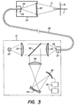
- FIG. 3 describes a seventh embodiment of the invention using a miltimode 26 optical fiber, the diameter of the core of which is between approximately 10 and 100 ⁇ m connecting a measurement head 20 and an optoelectric system 21.
- This system 21 is intended to generate a polychranatic light beam and to analyze the light reflected by a surface element 31 whose position is sought.
- a polychromatic light source 22 makes it possible to direct a diverging beam towards a first refractive lens 23 intended to make this beam parallel.
- a second refractive lens 24 focuses said beam on the first end 25 of the optical fiber 26 fixed by a connector 27.
- a second connector 29 makes the second end 28 of the optical fiber 26 integral with the measuring head 20.
- the end 28 acts as a point light source and directs the waves ⁇ 1 to ⁇ n constituting the beam from the source 22 on a holographic lens 30.
- This lens converts the light waves as a function of their wavelength respective, to form a focal point F.
- the waves reflected by the surface element 31 on the lens 30 are focused by the latter on the end 28 of the optical fiber 26.
- the end 25 acts as a point source of light waves reflected by the surface element 31 on the lens 30, to direct these on the lens 24 whose role is to form a parallel beam of said reflected waves.
- a semi-transparent mirror 32 placed between the lenses 23 and 24, directs the parallel beam of the reflected waves towards a converging refractive lens 33 which directs these waves on a diffraction grid 34 similar to the grid 6 of FIG. 1.
- the waves diffracted by the grid 34 are directed onto a network of photodetectors 35, analogous to the network 7 of FIG. 1.
- the electrical signals coming from the photodetectors are processed by a logic assembly 36 associating the functions of the comparator 8 and of the computer 9 of FIG. 1 .
- a diaphragm such as the diaphragm 10 of FIG. 1 is not useful because the inlet 28 of the optical fiber 26 has an effect similar to this diaphragm as regards the at least partial elimination of the waves focused outside the surface element and as regards the stopping of the waves reflected by the lens 30
- the sensor according to the invention obviously makes it possible to carry out dynamic measurements by studying the modifications of the spectrum of the reflected light as a function of time. Analysis of this spectrum at regular intervals measure the displacements of a surface element.
- This last variant of use can in particular find an application in the servo-control in position, in speed, or in acceleration, of a robot arm, or in the control of machining machines.
- the device according to the invention can advantageously be used in all cases where a contactless distance measurement is desirable.
- the light spectrum analysis system described above is given by way of example. Those skilled in the art can easily adopt any other existing spectral analysis system. It will, for example, be possible to use an analysis system comprising a diffraction grid animated by oscillatory movements to successively direct each diffracted wave on a single photodetector. When the photodetector measures a maximum light intensity, the corresponding position of the grid will be representative of the position of the surface element in the focal point of the lens, therefore of the distance separating the surface element from the sensor. In another embodiment of the spectrum analysis system of the reflected light, the diffraction grid could be fixed and the photodetector mobile.
Abstract
Ce procédé permet de déterminer la position d'un objet (4) situé dans le lieu de focalisation d'un faisceau lumineux polychromatique (λ1, λ2, λn), formé par une lentille holographique (3), en analysant le spectre de la lumière réfléchie par l'objet et en déterminant ensuite la longueur d'onde du faisceau réfléchi (λ2) dont la densité est maximale. Cette longueur d'onde (λ2) est caractéristique de la position de l'objet (4) par rapport à la lentille holographique (3) ou à tout point du lieu de focalisation.This method makes it possible to determine the position of an object (4) located in the focal point of a polychromatic light beam (λ1, λ2, λn), formed by a holographic lens (3), by analyzing the spectrum of the light. reflected by the object and then determining the wavelength of the reflected beam (λ2) whose density is maximum. This wavelength (λ2) is characteristic of the position of the object (4) relative to the holographic lens (3) or at any point of the focal point.
Description
La présente invention a pour objet un procédé et un dispositif pour déterminer la position d'un élément de surface d'un objet par rapport à une échelle de référence, du type dans lequel on focalise un faisceau lumineux englobant une pluralité d'ondes lumineuses en une pluralité de points correspondant aux foyers de chaque onde, et l'on détermine la longueur d'onde dont le point de focalisation se trouve sur cet élément de surface.The subject of the present invention is a method and a device for determining the position of a surface element of an object with respect to a reference scale, of the type in which a light beam focusing including a plurality of light waves is focused. a plurality of points corresponding to the foci of each wave, and the wavelength whose focal point is on this surface element is determined.
On connaît déjà les brevets DE 19 62515 et GB 2 077 421 décrivant un procédé et des dispositifs de ce genre.We already know the patents DE 19 62515 and
Le brevet DE 19 62515 traite d'un capteur de distance optique sans contact, dans lequel un faisceau lumineux est focalisé en une pluralité de foyers distincts. Ce capteur permet de déterminer la position d'un objet se trouvant entre deux de ces foyers. On conpa- re l'intensité respective des deux ondes lumineuses réfléchies par l'objet et convergeant en ces foyers. La position de l'objet par rapport au capteur est définie lorsque ces ondes ont une intensité égale. On déplace le capteur pour obtenir cette égalité. La position finale du capteur permet de situer l'objet. Ce capteur est en fait un capteur hybride, puisqu'il conporte un système de mesure mécanique (repérage de la position du capteur) et optique (localisation de l'objet par rapport au capteur)Patent DE 19 62515 deals with a non-contact optical distance sensor, in which a light beam is focused in a plurality of distinct focal points. This sensor makes it possible to determine the position of an object located between two of these foci. We compare the respective intensity of the two light waves reflected by the object and converging in these foci. The position of the object relative to the sensor is defined when these waves have an equal intensity. We move the sensor to obtain this equality. The final position of the sensor makes it possible to locate the object. This sensor is in fact a hybrid sensor, since it includes a mechanical (location of the sensor position) and optical (location of the object relative to the sensor) measurement system.
Le brevet GB 2 077 421 décrit un capteur optique et un procédé pour mesurer les délacements d'un objet, où l'on focalise deux faisceaux monochromatiques de couleur différente, d'intensité égale, à axes confondus, pour obtenir deux points de focalisation distincts situés à égale distance d'un plan de référence. On mesure l'intensité relative des ondes lumineuses des deux faisceaux, après réflexion par l'objet. Cette intensité relative peut être caractérisée par la différence ou par le quotient des intensités respectives des ondes lumineuses. L'évolution de la valeur de cette intensité relative est caractéristique des déplacements de l'objet.
Dans les deux cas ci-dessus, on détermine la position d'un objet en comparant deux signaux optiques. La précision de cette comparaison est à l'évidence liée à l'intensité des signaux. En conséquence, la précision et le pouvoir de résolution de tels capteurs sont très étroitement liés aux propriétés optiques de la surface de l'objet à situer.In the two cases above, we determine the position of an ob jet by comparing two optical signals. The accuracy of this comparison is obviously linked to the intensity of the signals. Consequently, the precision and the resolving power of such sensors are very closely linked to the optical properties of the surface of the object to be located.
La présente invention a pour but de remédier aux défauts des capteurs existants.The object of the present invention is to remedy the faults of existing sensors.
A cet effet, l'invention a, tout d'abord, pour objet un procédé pour mesurer la position d'un élément de surface par rapport à une référence, selon la revendication 1.To this end, the invention firstly relates to a method for measuring the position of a surface element relative to a reference, according to
L'invention a, de plus, pour objet un dispositif pour la mise en oeuvre de ce procédé, selon la revendication 3.The invention further relates to a device for implementing this method, according to
Le dessin annexé illustre très schématiquement, et à titre d'exemple, deux formes d'exécution du dispositif selon l'invention, ainsi qu'un diagramme explicatif.
- La figure 1 est une représentation schématique d'une première forme d'exécution du dispositif selon l'invention.
- La figure 2 est un diagramme explicatif représentant une courbe d'étalonnage.
- La figure 3 est une représentation schématique d'une autre forme d'exécution du dispositif selon l'invention.
- Figure 1 is a schematic representation of a first embodiment of the device according to the invention.
- Figure 2 is an explanatory diagram showing a calibration curve.
- Figure 3 is a schematic representation of another embodiment of the device according to the invention.
Le dispositif de la figure 1 comprend une source de lumière polychromatique 1, générant un faisceau lumineux. Cette source peut par exemple être une lampe à filament de tungstène, une lampe à arc concentré, ou autre. L'axe 2 de ce faisceau est dirigé sur un élément de surface 4 dont la position est à déterminer et susceptible de réfléchir au moins partiellement les ondes lumineuses. Une lentille holographique 3, à raies concentriques circulaires d'un type courant, focalise les diverses ondes constituant le faisceau en fonction de leur longueur d'onde respective λ1, λ2....λn.The device of FIG. 1 comprises a
Si l'on ne prend en considération que les diffractions d'ordre 1, ces diverses ondes lumineuses sont focalisées en une pluralité de foyers (F1, F2....Fn) dont l'ensenble constitue un lieu de focalisation F. Pour ce type de lentille holographique, la distance focale est en première approximation proportionnelle à l'inverse de la longueur d'onde de l'onde focalisée. Un diviseur de rayons lumineux tel qu'un miroir semi-transparent 5 dirige les ondes lumineuses issues de la source 1 focalisées par la lentille 3 et réfléchies par l'élément de surface 4 vers une grille de diffraction concave 6. Cette grille de diffraction décompose le spectre de la lumière réfléchie par l'élément de surface et fait converger les ondes de ce spectre sur un réseau linéaire de photodétecteurs 7, chacun de ces photodétecteurs étant considéré comme ponctuel. Ce réseau peut, par exemple, être un circuit CCD. La grille de diffraction 6 dévie les ondes lumineuses selon la relation:
- a. (sinoα + sinβ) = kλ
- où a est la distance séparant deux raies de la
grille 6, - αest l'angle d'incidence des ondes lumineuses,
- βest l'angle de diffraction de ces ondes,
- k est un nombre entier, (pour les diffractions du 1er ordre,
- k 1) et À est la longueur d'onde de la lumière incidente.
- at. (sinoα + sinβ) = kλ
- where a is the distance between two lines of
grid 6, - α is the angle of incidence of the light waves,
- β is the diffraction angle of these waves,
- k is an integer, (for 1st order diffractions,
- k 1) and A is the wavelength of the incident light.
Les ondes du spectre de la lumière réfléchie, diffractées par la grille 6, convergent sur le réseau de photodétecteurs (Pl, P2······ Pn) en des zones dont les surfaces respectives sont d'autant plus grandes que les foyers correspondants (F1, F2... Fn) du lieu F sont éloignés de l'élément de surface 4. Il suffit dès lors de mesurer ponctuellement l'intensité lumineuse en chacune de ces zones, au moyen d'un ou de plusieurs photodétecteurs, pour obtenir une information caractéristique de la densité lumineuse en cette zone, donc de la densité de l'onde lumineuse convergeant en cette zone. Un analyseur 8 compare entre elles les intensités respectives des signaux électriques (I1, I2... In) issus des photodétecteurs, représentatives de la densité respective des ondes lumineuses dirigées sur chacun desdits photodétecteurs, pour rechercher l'onde λ2 du spectre de la lumière réfléchie dont la densité est maximale. Un calculateur 9 introduit cette longueur d'onde λ2 dans une fonction d'étalonnage r (A) propre à la lentille 3. Cette fonction associe une distance de focalisation à chaque onde focalisée par la lentille.The waves of the spectrum of the reflected light, diffracted by the
Dans un but simplificateur, la figure 1 ne représente qu'une seule source lumineuse, mais il est bien évident que l'on peut utiliser une pluralité de sources disposées par exemple côte-à-cote dans un plan sensiblement orthogonal à l'axe 2 du faisceau lumineux, ces sources pouvant être alignées sur un ou plusieurs rangs. L'ensenble iu dispositif est alors conçu de manière à pouvoir conparer les densités respectives de plusieurs images constituées chacune d'un ensemble de zones alignées sur un ou plusieurs rangs.For the sake of simplicity, FIG. 1 represents only one light source, but it is obvious that a plurality of sources can be used, for example arranged side by side in a plane substantially orthogonal to
La figure 2 montre un exemple de courbe d'étalonnage d'une lentille holographique- à 270 raies concentriques circulaires, dont la raie extérieure a environ 5 mm de diamètre. Les distances de focaLisation sont représentées en abscisse et les longueurs d'onde en ordonnée. Pour obtenir cette courbe, on a focalisé six faisceaux lumineux monochromatiques de longueur d'onde connue au moyen de la lentille holographique à étalonner. On a ensuite placé un miroir dans le lieu de focalisation de la lentille, et l'on a mesuré, pour chaque faisceau, la position du miroir pour laquelle la densité de la lumière réfléchie était maximale.FIG. 2 shows an example of a calibration curve for a holographic lens with 270 circular concentric lines, the external line of which is approximately 5 mm in diameter. The focusing distances are shown on the abscissa and the wavelengths on the ordinate. To obtain this curve, six monochromatic light beams of known wavelength were focused by means of the holographic lens to be calibrated. A mirror was then placed in the focal point of the lens, and the position of the mirror for which the density of the reflected light was maximum was measured for each beam.
Le calculateur 9 génère un signal Xi=r(λ2) caractéristique de la position de l'élément de surface 4 par rapport à un point de référence ou une échelle de référence. La position du point de référence, respectivement la position de l'échelle de référence, est définie par la courbe d'étalonnage r(λ). Le point de référence peut par exemple être constitué par la lentille 3. L'échelle de référence peut notamment être constituée par tout ou partie du lieu de focalisation F.The
Pour certains modèles de lentilles holographiques à raies circulaires, il est également possible de mesurer les diffractions d'ordre 2 et même parfois les diffractions d'ordre supérieur à 2. Les diffractions du deuxième ordre focalisent une portion des ondes de longueur d'onde λ1 λ2... λn sur des foyers Fi, F2... Fn constituant un lieu de focalisation secondaire F' situé entre le lieu de focalisation F et la lentille. L'intensité des ondes focalisées en F' est plus faible que celle des ondes focalisées en F. Il est malgré tout possible d'analyser le spectre de lumière réfléchie par un éventuel objet placé dans ce lieu de focalisation secondaire. Il est ainsi possible de définir au moins deux lieux de focalisation pour chaque lentille holographique et donc de définir au moins deux domaines de mesure distincts pour un même capteur.For certain models of holographic lenses with circular lines, it is also possible to measure the diffractions of
Une portion de lumière du faisceau issu de la source 1 est réfléchie par la lentille holographique 3. Cette lumière parasite se superpose aux ondes réfléchies par l'élément de surface 4, constituant ainsi une source non négligeable de bruit de fond. Dans une δυχème forme d'exécution de l'invention, il est possible de remédier à ce défaut en remplaçant la lentille 3 à raies concentriques circulaires par une lentille à raies concentriques légèrement elliptiques, inclinée d'au plus quelques degrés d'angle par rapport au plan normal à l'axe 2 du faisceau lumineux. Cette disposition permet de diriger la portion de lumière parasite réfléchie par la lentille hors du faisceau d'ondes réfléchies par l'élément de surface 4.A portion of light from the beam from
Dans une troisième forme d'exécution de l'invention, il est avantageux de disposer un diaphragme à orifice circulaire 10, entre le miroir 5 et la grille de diffraction concave du système d'analyse spectrale, à l'endroit de section minimale de la portion du faisceau lumineux réfléchi par l'élément de surface, de longueur d'onde λ2. Ce diaphragme élimine du faisceau réfléchi une portion des ondes qui sont focalisées hors de l'élément de surface, ces ondes apparaissant chacune sur cet élément de surface sous la forme d'un disque dont le diamètre est proportionnel à la distance séparant les foyers respectifs de ces ondes de l'élément de surface; pour autant que les diamètres de ces disques soient supérieurs au diamètre du diaphragme. Le diaphragme stoppe de plus partiellement les ondes réfléchies par la lentille 3; il permet dont de mieux mettre en évidence l'onde A2 focalisée sur l'élément de surface.In a third embodiment of the invention, it is advantageous to have a diaphragm with a
Dans une quatrième forme d'exécution du dispositif selon l'invention, un système optique classique amovible, constitué d'au moins une lentille réfractive, est placé entre la lentille 3 et son lieu de focalisation F. Il permet d'adapter une seule lentille 3 à de nan- breuses applications différentes, en déplaçant à volonté le lieu F par rapport à la lentille 3.In a fourth embodiment of the device according to the invention, a removable conventional optical system, consisting of at least one refractive lens, is placed between the
Dans une cinquième forme d'exécution du dispositif selon l'invention, il est possible d'utiliser une lentille réfractive à aberration chromatique élevée, en lieu et place de la lentille holographique 3, pour focaliser les ondes lumineuses du faisceau 2 en une pluralité de foyer F1 P2... Fn. Le lieu de focalisation d'une telle lentille réfractive est nettement plus court que celui d'une lentille halographique; à ce titre, les deux types de lentilles sont complémentaires.In a fifth embodiment of the device according to the invention, it is possible to use a refractive lens with high chromatic aberration, in place of the
Dans une sixième forme d'exécution du dispositif selon l'invention, on utilise une lentille holographique à raies parallèles dite lentille holographique cylindrique. Ce type de lentille se distingue des lentilles à raies circulaires par la forme de son lieu de focalisation constitué d'une pluralité de foyers F1, F2,... Fn en forme de segments de droites parallèles aux raies de la lentille.In a sixth embodiment of the device according to the invention, a holographic lens with parallel lines is used, called a cylindrical holographic lens. This type of lens differs from lenses with circular lines by the shape of its focal point consisting of a plurality of focal points F 1 , F 2 , ... F n in the form of straight line segments parallel to the lines of the lens.
Cette forme d'exécution peut être utilisée pour mesurer la distance séparant deux éléments de surface adjacents a et b, non coplanaires. Dans ce cas, le système d'analyse du spectre de la lumière réfléchie met en évidence deux ondes lumineuses λa et λb focalisées sur l'élément de surface a, respectivement sur l'élément de surface b. La distance cherchée est la différence des distances respectives de chaque élément de surface à la lentille. Ces distances sont déterminées came précédemmnent à l'aide de la courbe d'étalonnage propre à la lentille à raies parallèles. Cette forme d'exécution permet de plus de trouver la position latérale dans le lieu de focalisation de la ligne de séparation des éléments de surface a et b par la comparaison de l'intensité relative des ondes λa et λb réfléchies par chacun desdits éléments de surface.This embodiment can be used to measure the distance separating two non-coplanar adjacent surface elements a and b. In this case, the system for analyzing the spectrum of the reflected light highlights two light waves λ a and λ b focused on the surface element a, respectively on the surface element b. The distance sought is the difference of the respective distances from each surface element to the lens. These distances are determined beforehand using the calibration curve specific to the lens with parallel lines. This embodiment also makes it possible to find the lateral position in the focal point of the line of separation of the surface elements a and b by comparing the relative intensity of the waves λ a and λ b reflected by each of said elements. of surface.
La figure 3 décrit une septième forme d'exécution de l'invention utilisant une fibre optique miltimode 26, dont le diamètre du coeur est compris entre environ 10 et 100 µm reliant une tête de mesure 20 et un système opto-électrique 21. Ce système 21 est destiné à générer un faisceau lumineux polychranatique et à analyser la lumière réfléchie par un élément de surface 31 dont on cherche la position. Une source lumineuse polychromatique 22 permet de diriger un faisceau divergeant vers une première lentille réfractive 23 destinée à rendre ce faisceau parallèle. Une seconde lentille réfractive 24 focalise ledit faisceau sur la première extrémité 25 de la fibre optique 26 fixée par un connecteur 27. Un second connecteur 29 rend la seconde extrémité 28 de la fibre optique 26 solidaire de la tête de mesure 20. L'extrémité 28 agit comme source lumineuse ponctuelle et dirige les ondes λ1 à λn constituant le faisceau issu de la source 22 sur une lentille holographique 30. Cette lentille fait converger les ondes lumineuses en fonction de leur longueur d'onde respective, pour former un lieu de focalisation F. Les ondes réfléchies par l'élément de surface 31 sur la lentille 30 sont focalisées par cette dernière sur l'extrémité 28 de la fibre optique 26. L'extrémité 25 agit comme source ponctuelle d'ondes lumineuses réfléchies par l'élément de surface 31 sur la lentille 30, pour diriger celles-ci sur la lentille 24 dont le rôle est de former un faisceau parallèle desdites ondes réfléchies. Un miroir semi-transparent 32, placé entre les lentilles 23 et 24, dirige le faisceau parallèle des ondes réfléchies vers une lentille réfractive convergeante 33 qui dirige ces ondes sur une grille de diffraction 34 analogue à la grille 6 de la figure 1. Les ondes diffractées par la grille 34 sont dirigées sur un réseau de photodétecteurs 35, analogue au réseau 7 de la figure 1. Les signaux électriques issus des photodétecteurs sont traités par un ensemble logique 36 associant les fonctions du comparateur 8 et du calculateur 9 de la figure 1.FIG. 3 describes a seventh embodiment of the invention using a
Il faut relever que, dans cette forme d'exécution, un diaphragme tel que le diaphragme 10 de la figure 1 n'est pas utile car l'entrée 28 de la fibre optique 26 a un effet analogue à ce diaphragme en ce qui concerne l'élimination au moins partielle des ondes focalisées hors de l'élément de surface et en ce qui concerne l'arrêt des ondes réfléchies par la lentille 30It should be noted that, in this embodiment, a diaphragm such as the
A titre d'exemple d'application du capteur selon l'invention, il est possible de mesurer la largeur d'une pièce mécanique. Dans ce but, deux capteurs placés en opposition de part et d'autre de la pièce à mesurer permettent de trouver la largeur de ladite pièce par la relation:
- avec: X = dimension cherchée,
- d = distance séparant les deux capteurs,
- X1 = distance séparant la pièce du premier capteur
- X2 = distance séparant la pièce du deuxième capteur.
- with: X = dimension sought,
- d = distance separating the two sensors,
- X 1 = distance between the room and the first sensor
- X 2 = distance between the room and the second sensor.
Le capteur selon l'invention permet évidemment d'effectuer des mesures dynamiques en étudiant les modifications du spectre de la lumière réfléchie en fonction du temps. L'analyse de ce spectre à intervalles réguliers permet de mesurer les déplacements d'un élément de surface. Cette dernière variante d'utilisation peut notamment trouver une application dans l'asservissement en position, en vitesse, ou en accélération, d'un bras de robot, ou dans la commande des machines d'usinage.The sensor according to the invention obviously makes it possible to carry out dynamic measurements by studying the modifications of the spectrum of the reflected light as a function of time. Analysis of this spectrum at regular intervals measure the displacements of a surface element. This last variant of use can in particular find an application in the servo-control in position, in speed, or in acceleration, of a robot arm, or in the control of machining machines.
Les exemples d'application mentionnés ne constituent pas une liste exhaustive: le dispositif selon l'invention pourra avantageusement être utilisé dans tous les cas où une mesure de distance sans contact est souhaitable.The application examples mentioned do not constitute an exhaustive list: the device according to the invention can advantageously be used in all cases where a contactless distance measurement is desirable.
Il faut noter que le système d'analyse du spectre lumineux décrit ci-dessus est donné à titre d'exemple. L'homme du métier pourra facilement adopter tout autre système d'analyse spectrale existant. Il sera, par exemple, possible d'utiliser un système d'analyse comportant une grille de diffraction animée de mouvements oscillatoires pour diriger successivement chaque onde diffractée sur un photodétecteur unique. Lorsque le photodétecteur mesurera une intensité lumineuse maximale, la position correspondante de la grille sera représentative de la position de l'élément de surface dans le lieu de focalisation de la lentille, donc de la distance séparant l'élément de surface du capteur. Dans une autre forme d'exécution du système d'analyse du spectre de la lumière réfléchie, la grille de diffraction pourrait être fixe et le photodétecteur mobile. On peut évi- demτent utiliser des moyens autres qu'une grille de diffraction pour décomposer le spectre du faisceau réfléchi par l'élément de surface; à titre d'exemple non limitatif, ces moyens pouvant être constitués d'un prisme de dispersion ou d'un filtre spectral à couches minces.It should be noted that the light spectrum analysis system described above is given by way of example. Those skilled in the art can easily adopt any other existing spectral analysis system. It will, for example, be possible to use an analysis system comprising a diffraction grid animated by oscillatory movements to successively direct each diffracted wave on a single photodetector. When the photodetector measures a maximum light intensity, the corresponding position of the grid will be representative of the position of the surface element in the focal point of the lens, therefore of the distance separating the surface element from the sensor. In another embodiment of the spectrum analysis system of the reflected light, the diffraction grid could be fixed and the photodetector mobile. One can obviously use means other than a diffraction grid to decompose the spectrum of the beam reflected by the surface element; by way of nonlimiting example, these means may consist of a dispersion prism or a spectral filter with thin layers.
Claims (8)
Applications Claiming Priority (2)
| Application Number | Priority Date | Filing Date | Title |
|---|---|---|---|
| CH4950/83 | 1983-09-12 | ||
| CH4950/83A CH663466A5 (en) | 1983-09-12 | 1983-09-12 | METHOD AND DEVICE FOR DETERMINING THE POSITION OF AN OBJECT IN RELATION TO A REFERENCE. |
Publications (1)
| Publication Number | Publication Date |
|---|---|
| EP0142464A1 true EP0142464A1 (en) | 1985-05-22 |
Family
ID=4285347
Family Applications (1)
| Application Number | Title | Priority Date | Filing Date |
|---|---|---|---|
| EP84810435A Withdrawn EP0142464A1 (en) | 1983-09-12 | 1984-09-10 | Process and device to determine the position of an object with respect to a reference |
Country Status (4)
| Country | Link |
|---|---|
| US (1) | US4585349A (en) |
| EP (1) | EP0142464A1 (en) |
| JP (1) | JPS6073405A (en) |
| CH (1) | CH663466A5 (en) |
Cited By (9)
| Publication number | Priority date | Publication date | Assignee | Title |
|---|---|---|---|---|
| GB2188144A (en) * | 1986-03-20 | 1987-09-23 | Smiths Industries Plc | Optical transducers |
| WO1988010406A1 (en) * | 1987-06-26 | 1988-12-29 | Battelle-Institut E.V. | Device for measuring distances between an optical element with high chromatic aberration and an object |
| DE3938714A1 (en) * | 1989-11-23 | 1991-05-29 | Bernd Dr Breuckmann | Optical determination of object shapes, shape variations - using structured coloured light projected onto objects for high resolution, dynamic measurement |
| WO1996041123A1 (en) * | 1995-06-07 | 1996-12-19 | Keravision, Inc. | Distance measuring confocal microscope |
| FR2738343A1 (en) * | 1995-08-30 | 1997-03-07 | Cohen Sabban Joseph | Optical microstratigraphy equipment |
| WO1998044375A2 (en) * | 1997-03-29 | 1998-10-08 | Carl Zeiss Jena Gmbh | Confocal microscopic device |
| WO2008058281A2 (en) * | 2006-11-09 | 2008-05-15 | Amo Wavefront Sciences, Llc | Method and apparatus for obtaining the distance from an optical measurement instrument to and object under test |
| WO2010097523A1 (en) | 2009-02-25 | 2010-09-02 | Altatech Semiconductor | Device and method for inspecting semiconductor wafers |
| EP3567339A1 (en) * | 2018-05-10 | 2019-11-13 | Nanovea, Inc. | 3d surface scanning white light axial chromatism device and method |
Families Citing this family (170)
| Publication number | Priority date | Publication date | Assignee | Title |
|---|---|---|---|---|
| US4742222A (en) * | 1984-07-23 | 1988-05-03 | Tavkozlesi Kutato Intezet | Selective optical detector apparatus utilizing longitudinal chromatic aberration |
| GB8625471D0 (en) * | 1986-10-24 | 1986-11-26 | Bicc Plc | Displacement detection |
| US4871252A (en) * | 1986-10-30 | 1989-10-03 | The Regents Of The University Of California | Method and apparatus for object positioning |
| US4868401A (en) * | 1988-10-03 | 1989-09-19 | Erickson Ronnie D | Method and means for measuring distance of a moving object from a fixed point of reference |
| DE3841742A1 (en) * | 1988-12-10 | 1990-06-13 | Hueser Teuchert Dorothee | Coordinate probe employing a contactless measuring principle of absolute interferometry |
| GB8923994D0 (en) * | 1989-10-25 | 1989-12-13 | Smiths Industries Plc | Optical transducers |
| DE4025577C2 (en) * | 1990-08-11 | 1999-09-09 | Fraunhofer Ges Forschung | Device for the contactless measurement of the distance from an object |
| JPH0611323A (en) * | 1992-06-26 | 1994-01-21 | Minolta Camera Co Ltd | Shape measuring instrument |
| JP3206843B2 (en) * | 1992-12-18 | 2001-09-10 | 株式会社小松製作所 | 3D image measurement device |
| US5608529A (en) * | 1994-01-31 | 1997-03-04 | Nikon Corporation | Optical three-dimensional shape measuring apparatus |
| IL121267A0 (en) * | 1997-07-09 | 1998-01-04 | Yeda Res & Dev | Method and device for determining the profile of an object |
| EP0890822A3 (en) * | 1997-07-09 | 2000-04-05 | YEDA RESEARCH AND DEVELOPMENT Co. LTD. | A triangulation method and system for color-coded optical profilometry |
| DE19732376C1 (en) * | 1997-07-25 | 1999-02-18 | Fraunhofer Ges Forschung | Method of distance measurement using triangulation principle |
| US6341036B1 (en) * | 1998-02-26 | 2002-01-22 | The General Hospital Corporation | Confocal microscopy with multi-spectral encoding |
| FR2779517B1 (en) * | 1998-06-05 | 2000-08-18 | Architecture Traitement D Imag | METHOD AND DEVICE FOR OPTOELECTRIC ACQUISITION OF SHAPES BY AXIAL ILLUMINATION |
| IL125659A (en) * | 1998-08-05 | 2002-09-12 | Cadent Ltd | Method and apparatus for imaging three-dimensional structure |
| AU3032700A (en) | 1999-01-08 | 2000-07-24 | Ibsen Micro Structures A/S | Spectrometer |
| US6724489B2 (en) * | 2000-09-22 | 2004-04-20 | Daniel Freifeld | Three dimensional scanning camera |
| AU2002230842A1 (en) * | 2000-10-30 | 2002-05-15 | The General Hospital Corporation | Optical methods and systems for tissue analysis |
| US9295391B1 (en) * | 2000-11-10 | 2016-03-29 | The General Hospital Corporation | Spectrally encoded miniature endoscopic imaging probe |
| EP2333523B1 (en) * | 2001-04-30 | 2020-04-08 | The General Hospital Corporation | Method and apparatus for improving image clarity and sensitivity in optical coherence tomography using dynamic feedback to control focal properties and coherence gating |
| AT503309B1 (en) * | 2001-05-01 | 2011-08-15 | Gen Hospital Corp | DEVICE FOR DETERMINING ATHEROSCLEROTIC BEARING BY MEASURING OPTICAL TISSUE PROPERTIES |
| DE10125885B4 (en) * | 2001-05-28 | 2004-09-16 | Siemens Ag | Sensor device for fast optical distance measurement according to the confocal optical imaging principle |
| US6917421B1 (en) * | 2001-10-12 | 2005-07-12 | Kla-Tencor Technologies Corp. | Systems and methods for multi-dimensional inspection and/or metrology of a specimen |
| US6980299B1 (en) | 2001-10-16 | 2005-12-27 | General Hospital Corporation | Systems and methods for imaging a sample |
| ATE503982T1 (en) * | 2002-01-11 | 2011-04-15 | Gen Hospital Corp | DEVICE FOR OCT IMAGE ACQUISITION WITH AXIAL LINE FOCUS FOR IMPROVED RESOLUTION AND DEPTH OF FIELD |
| US7355716B2 (en) * | 2002-01-24 | 2008-04-08 | The General Hospital Corporation | Apparatus and method for ranging and noise reduction of low coherence interferometry LCI and optical coherence tomography OCT signals by parallel detection of spectral bands |
| US8614768B2 (en) * | 2002-03-18 | 2013-12-24 | Raytheon Company | Miniaturized imaging device including GRIN lens optically coupled to SSID |
| US20110201924A1 (en) * | 2002-04-30 | 2011-08-18 | The General Hospital Corporation | Method and Apparatus for Improving Image Clarity and Sensitivity in Optical Tomography Using Dynamic Feedback to Control Focal Properties and Coherence Gating |
| DE10242373B4 (en) * | 2002-09-12 | 2009-07-16 | Siemens Ag | Confocal distance sensor |
| DE10242374A1 (en) * | 2002-09-12 | 2004-04-01 | Siemens Ag | Confocal distance sensor |
| JP2006516739A (en) * | 2003-01-24 | 2006-07-06 | ザ・ジェネラル・ホスピタル・コーポレイション | System and method for identifying tissue using a low coherence interferometer |
| US8054468B2 (en) * | 2003-01-24 | 2011-11-08 | The General Hospital Corporation | Apparatus and method for ranging and noise reduction of low coherence interferometry LCI and optical coherence tomography OCT signals by parallel detection of spectral bands |
| US7567349B2 (en) * | 2003-03-31 | 2009-07-28 | The General Hospital Corporation | Speckle reduction in optical coherence tomography by path length encoded angular compounding |
| KR101546024B1 (en) | 2003-06-06 | 2015-08-20 | 더 제너럴 하스피탈 코포레이션 | Process and apparatus for a wavelength tunning source |
| US20050083534A1 (en) * | 2003-08-28 | 2005-04-21 | Riza Nabeel A. | Agile high sensitivity optical sensor |
| KR101384553B1 (en) | 2003-10-27 | 2014-04-11 | 더 제너럴 하스피탈 코포레이션 | Method and apparatus for performing optical imaging using frequency-domain interferometry |
| WO2005054780A1 (en) * | 2003-11-28 | 2005-06-16 | The General Hospital Corporation | Method and apparatus for three-dimensional spectrally encoded imaging |
| DE102004007213A1 (en) * | 2004-02-13 | 2005-09-08 | Siemens Ag | Confocal distance sensor |
| EP1754016B1 (en) * | 2004-05-29 | 2016-05-18 | The General Hospital Corporation | Process, system and software arrangement for a chromatic dispersion compensation using reflective layers in optical coherence tomography (oct) imaging |
| WO2005121700A1 (en) * | 2004-06-08 | 2005-12-22 | Micro-Epsilon Messtechnik Gmbh & Co. Kg | Device and method for inspecting the internal surfaces of holes |
| US7447408B2 (en) | 2004-07-02 | 2008-11-04 | The General Hospital Corproation | Imaging system and related techniques |
| KR101332222B1 (en) * | 2004-08-06 | 2013-11-22 | 더 제너럴 하스피탈 코포레이션 | Process, system and software arrangement for determining at least one location in a sample using an optical coherence tomography |
| EP2272421A1 (en) | 2004-08-24 | 2011-01-12 | The General Hospital Corporation | Method and apparatus for imaging of vessel segments |
| JP5334415B2 (en) | 2004-08-24 | 2013-11-06 | ザ ジェネラル ホスピタル コーポレイション | Process, system and software for measuring mechanical strain and elastic properties of samples |
| US7365859B2 (en) * | 2004-09-10 | 2008-04-29 | The General Hospital Corporation | System and method for optical coherence imaging |
| US7366376B2 (en) * | 2004-09-29 | 2008-04-29 | The General Hospital Corporation | System and method for optical coherence imaging |
| DE102004049541A1 (en) * | 2004-10-12 | 2006-04-20 | Precitec Optronik Gmbh | Measuring system for measuring surfaces and calibration method therefor |
| JP5175101B2 (en) * | 2004-10-29 | 2013-04-03 | ザ ジェネラル ホスピタル コーポレイション | System and method for performing Jones matrix based analysis to measure unpolarized polarization parameters using polarization sensitive optical coherence tomography |
| EP1807722B1 (en) * | 2004-11-02 | 2022-08-10 | The General Hospital Corporation | Fiber-optic rotational device, optical system for imaging a sample |
| EP2278266A3 (en) * | 2004-11-24 | 2011-06-29 | The General Hospital Corporation | Common-Path Interferometer for Endoscopic OCT |
| US7477401B2 (en) * | 2004-11-24 | 2009-01-13 | Tamar Technology, Inc. | Trench measurement system employing a chromatic confocal height sensor and a microscope |
| US8922781B2 (en) | 2004-11-29 | 2014-12-30 | The General Hospital Corporation | Arrangements, devices, endoscopes, catheters and methods for performing optical imaging by simultaneously illuminating and detecting multiple points on a sample |
| JP2008538612A (en) * | 2005-04-22 | 2008-10-30 | ザ ジェネラル ホスピタル コーポレイション | Configuration, system, and method capable of providing spectral domain polarization sensitive optical coherence tomography |
| KR101410867B1 (en) | 2005-04-28 | 2014-06-23 | 더 제너럴 하스피탈 코포레이션 | Systems, processes and software arrangements for evaluating information associated with an anatomical structure by an optical coherence ranging technique |
| DE102005022125A1 (en) * | 2005-05-12 | 2006-11-16 | Carl Zeiss Microlmaging Gmbh | Light pattern microscope with auto focus mechanism, uses excitation or detection beam path with auto focus for detecting position of focal plane |
| US20070009935A1 (en) * | 2005-05-13 | 2007-01-11 | The General Hospital Corporation | Arrangements, systems and methods capable of providing spectral-domain optical coherence reflectometry for a sensitive detection of chemical and biological sample |
| TWI268339B (en) * | 2005-05-25 | 2006-12-11 | Ind Tech Res Inst | Displacement measuring device and method, an internal diameter measuring device by use of the variance of the wavelength to measure the displacement and the internal diameter |
| JP2008542758A (en) * | 2005-05-31 | 2008-11-27 | ザ ジェネラル ホスピタル コーポレイション | System, method and apparatus capable of using spectrally encoded heterodyne interferometry for imaging |
| EP1889037A2 (en) | 2005-06-01 | 2008-02-20 | The General Hospital Corporation | Apparatus, method and system for performing phase-resolved optical frequency domain imaging |
| DE602006017558D1 (en) * | 2005-08-09 | 2010-11-25 | Gen Hospital Corp | DEVICE AND METHOD FOR CARRYING OUT POLARIZATION-BASED QUADRATURE DEMODULATION IN OPTICAL COHERENCE TOMOGRAPHY |
| EP1937137B1 (en) * | 2005-09-29 | 2022-06-15 | General Hospital Corporation | Method and apparatus for optical imaging via spectral encoding |
| EP1945094B1 (en) * | 2005-10-14 | 2018-09-05 | The General Hospital Corporation | Spectral- and frequency- encoded fluorescence imaging |
| US8328731B2 (en) * | 2006-01-06 | 2012-12-11 | Phonak Ag | Method and system for reconstructing the three-dimensional shape of the surface of at least a portion of an ear canal and/or of a concha |
| JP5680826B2 (en) * | 2006-01-10 | 2015-03-04 | ザ ジェネラル ホスピタル コーポレイション | Data generation system using endoscopic technology for encoding one or more spectra |
| US9087368B2 (en) | 2006-01-19 | 2015-07-21 | The General Hospital Corporation | Methods and systems for optical imaging or epithelial luminal organs by beam scanning thereof |
| US8145018B2 (en) | 2006-01-19 | 2012-03-27 | The General Hospital Corporation | Apparatus for obtaining information for a structure using spectrally-encoded endoscopy techniques and methods for producing one or more optical arrangements |
| US20070223006A1 (en) * | 2006-01-19 | 2007-09-27 | The General Hospital Corporation | Systems and methods for performing rapid fluorescence lifetime, excitation and emission spectral measurements |
| US20070171433A1 (en) * | 2006-01-20 | 2007-07-26 | The General Hospital Corporation | Systems and processes for providing endogenous molecular imaging with mid-infrared light |
| US20070171430A1 (en) * | 2006-01-20 | 2007-07-26 | The General Hospital Corporation | Systems and methods for providing mirror tunnel micropscopy |
| EP2659852A3 (en) | 2006-02-01 | 2014-01-15 | The General Hospital Corporation | Apparatus for applying a plurality of electro-magnetic radiations to a sample |
| US10426548B2 (en) | 2006-02-01 | 2019-10-01 | The General Hosppital Corporation | Methods and systems for providing electromagnetic radiation to at least one portion of a sample using conformal laser therapy procedures |
| JP2009537024A (en) * | 2006-02-01 | 2009-10-22 | ザ ジェネラル ホスピタル コーポレイション | Apparatus for controlling at least one of at least two sites of at least one fiber |
| WO2007092911A2 (en) * | 2006-02-08 | 2007-08-16 | The General Hospital Corporation | Methods, arrangements and systems for obtaining information associated with an anatomical sample using optical microscopy |
| WO2007101026A2 (en) * | 2006-02-24 | 2007-09-07 | The General Hospital Corporation | Methods and systems for performing angle-resolved fourier-domain optical coherence tomography |
| US20070208400A1 (en) * | 2006-03-01 | 2007-09-06 | The General Hospital Corporation | System and method for providing cell specific laser therapy of atherosclerotic plaques by targeting light absorbers in macrophages |
| WO2007109540A2 (en) * | 2006-03-17 | 2007-09-27 | The General Hospital Corporation | Arrangement, method and computer-accessible medium for identifying characteristics of at least a portion of a blood vessel contained within a tissue using spectral domain low coherence interferometry |
| US7742173B2 (en) * | 2006-04-05 | 2010-06-22 | The General Hospital Corporation | Methods, arrangements and systems for polarization-sensitive optical frequency domain imaging of a sample |
| WO2007133961A2 (en) | 2006-05-10 | 2007-11-22 | The General Hospital Corporation | Processes, arrangements and systems for providing frequency domain imaging of a sample |
| WO2007133964A2 (en) * | 2006-05-12 | 2007-11-22 | The General Hospital Corporation | Processes, arrangements and systems for providing a fiber layer thickness map based on optical coherence tomography images |
| WO2008016927A2 (en) * | 2006-08-01 | 2008-02-07 | The General Hospital Corporation | Systems and methods for receiving and/or analyzing information associated with electro-magnetic radiation |
| EP2054712B1 (en) * | 2006-08-25 | 2015-10-07 | The General Hospital Corporation | Apparatus and methods for enhancing optical coherence tomography imaging using volumetric filtering techniques |
| FI119259B (en) * | 2006-10-18 | 2008-09-15 | Valtion Teknillinen | Determination of surface and thickness |
| WO2008049118A2 (en) | 2006-10-19 | 2008-04-24 | The General Hospital Corporation | Apparatus and method for obtaining and providing imaging information associated with at least one portion of a sample and effecting such portion(s) |
| EP2662674A3 (en) | 2007-01-19 | 2014-06-25 | The General Hospital Corporation | Rotating disk reflection for fast wavelength scanning of dispersed broadbend light |
| EP2102583A2 (en) * | 2007-01-19 | 2009-09-23 | The General Hospital Corporation | Apparatus and method for controlling ranging depth in optical frequency domain imaging |
| US20080206804A1 (en) * | 2007-01-19 | 2008-08-28 | The General Hospital Corporation | Arrangements and methods for multidimensional multiplexed luminescence imaging and diagnosis |
| US20080234586A1 (en) * | 2007-03-19 | 2008-09-25 | The General Hospital Corporation | System and method for providing noninvasive diagnosis of compartment syndrome using exemplary laser speckle imaging procedure |
| US9176319B2 (en) | 2007-03-23 | 2015-11-03 | The General Hospital Corporation | Methods, arrangements and apparatus for utilizing a wavelength-swept laser using angular scanning and dispersion procedures |
| US7791712B2 (en) * | 2007-03-27 | 2010-09-07 | Mitutoyo Corporation | Chromatic confocal sensor fiber interface |
| US7626705B2 (en) | 2007-03-30 | 2009-12-01 | Mitutoyo Corporation | Chromatic sensor lens configuration |
| US10534129B2 (en) | 2007-03-30 | 2020-01-14 | The General Hospital Corporation | System and method providing intracoronary laser speckle imaging for the detection of vulnerable plaque |
| US8045177B2 (en) * | 2007-04-17 | 2011-10-25 | The General Hospital Corporation | Apparatus and methods for measuring vibrations using spectrally-encoded endoscopy |
| US8115919B2 (en) * | 2007-05-04 | 2012-02-14 | The General Hospital Corporation | Methods, arrangements and systems for obtaining information associated with a sample using optical microscopy |
| US7835074B2 (en) | 2007-06-05 | 2010-11-16 | Sterling Lc | Mini-scope for multi-directional imaging |
| US7812971B2 (en) * | 2007-06-28 | 2010-10-12 | Quality Vision International, Inc. | Multi color autofocus apparatus and method |
| JP5917803B2 (en) * | 2007-07-31 | 2016-05-18 | ザ ジェネラル ホスピタル コーポレイション | System and method for emitting a beam scanning pattern for fast Doppler optical frequency domain imaging |
| US8040608B2 (en) * | 2007-08-31 | 2011-10-18 | The General Hospital Corporation | System and method for self-interference fluorescence microscopy, and computer-accessible medium associated therewith |
| WO2009059034A1 (en) * | 2007-10-30 | 2009-05-07 | The General Hospital Corporation | System and method for cladding mode detection |
| US7990522B2 (en) | 2007-11-14 | 2011-08-02 | Mitutoyo Corporation | Dynamic compensation of chromatic point sensor intensity profile data selection |
| US20090225324A1 (en) * | 2008-01-17 | 2009-09-10 | The General Hospital Corporation | Apparatus for providing endoscopic high-speed optical coherence tomography |
| US11123047B2 (en) | 2008-01-28 | 2021-09-21 | The General Hospital Corporation | Hybrid systems and methods for multi-modal acquisition of intravascular imaging data and counteracting the effects of signal absorption in blood |
| US9332942B2 (en) * | 2008-01-28 | 2016-05-10 | The General Hospital Corporation | Systems, processes and computer-accessible medium for providing hybrid flourescence and optical coherence tomography imaging |
| US7898656B2 (en) * | 2008-04-30 | 2011-03-01 | The General Hospital Corporation | Apparatus and method for cross axis parallel spectroscopy |
| WO2009137701A2 (en) | 2008-05-07 | 2009-11-12 | The General Hospital Corporation | System, method and computer-accessible medium for tracking vessel motion during three-dimensional coronary artery microscopy |
| GB0809037D0 (en) * | 2008-05-19 | 2008-06-25 | Renishaw Plc | Video Probe |
| JP5596027B2 (en) | 2008-06-18 | 2014-09-24 | レイセオン カンパニー | catheter |
| WO2009155432A2 (en) * | 2008-06-18 | 2009-12-23 | Sterling Lc | Miniaturized imaging device multiple grin lenses optically coupled to multiple ssids |
| US8861910B2 (en) | 2008-06-20 | 2014-10-14 | The General Hospital Corporation | Fused fiber optic coupler arrangement and method for use thereof |
| EP2309923B1 (en) | 2008-07-14 | 2020-11-25 | The General Hospital Corporation | Apparatus and methods for color endoscopy |
| US8486735B2 (en) * | 2008-07-30 | 2013-07-16 | Raytheon Company | Method and device for incremental wavelength variation to analyze tissue |
| US8445876B2 (en) * | 2008-10-24 | 2013-05-21 | Gigaphoton Inc. | Extreme ultraviolet light source apparatus |
| US9060704B2 (en) | 2008-11-04 | 2015-06-23 | Sarcos Lc | Method and device for wavelength shifted imaging |
| US7873488B2 (en) * | 2008-12-08 | 2011-01-18 | Mitutoyo Corporation | On-site calibration method and object for chromatic point sensors |
| US8937724B2 (en) * | 2008-12-10 | 2015-01-20 | The General Hospital Corporation | Systems and methods for extending imaging depth range of optical coherence tomography through optical sub-sampling |
| WO2010090837A2 (en) | 2009-01-20 | 2010-08-12 | The General Hospital Corporation | Endoscopic biopsy apparatus, system and method |
| EP2382456A4 (en) | 2009-01-26 | 2012-07-25 | Gen Hospital Corp | System, method and computer-accessible medium for providing wide-field superresolution microscopy |
| JP6053284B2 (en) | 2009-02-04 | 2016-12-27 | ザ ジェネラル ホスピタル コーポレイション | Apparatus and method for use of a high speed optical wavelength tuning source |
| US9351642B2 (en) | 2009-03-12 | 2016-05-31 | The General Hospital Corporation | Non-contact optical system, computer-accessible medium and method for measurement at least one mechanical property of tissue using coherent speckle technique(s) |
| US7876456B2 (en) * | 2009-05-11 | 2011-01-25 | Mitutoyo Corporation | Intensity compensation for interchangeable chromatic point sensor components |
| JP5819823B2 (en) * | 2009-07-14 | 2015-11-24 | ザ ジェネラル ホスピタル コーポレイション | Device for measuring the flow and pressure inside a blood vessel and method of operating the device |
| US9019349B2 (en) * | 2009-07-31 | 2015-04-28 | Naturalpoint, Inc. | Automated collective camera calibration for motion capture |
| WO2011041720A2 (en) | 2009-10-01 | 2011-04-07 | Jacobsen Stephen C | Method and apparatus for manipulating movement of a micro-catheter |
| US8717428B2 (en) | 2009-10-01 | 2014-05-06 | Raytheon Company | Light diffusion apparatus |
| WO2011041728A2 (en) | 2009-10-01 | 2011-04-07 | Jacobsen Stephen C | Needle delivered imaging device |
| US8828028B2 (en) | 2009-11-03 | 2014-09-09 | Raytheon Company | Suture device and method for closing a planar opening |
| EP2542145B1 (en) | 2010-03-05 | 2020-08-12 | The General Hospital Corporation | Systems which provide microscopic images of at least one anatomical structure at a particular resolution |
| US8134691B2 (en) * | 2010-03-18 | 2012-03-13 | Mitutoyo Corporation | Lens configuration for a thermally compensated chromatic confocal point sensor |
| US9069130B2 (en) | 2010-05-03 | 2015-06-30 | The General Hospital Corporation | Apparatus, method and system for generating optical radiation from biological gain media |
| WO2011149972A2 (en) | 2010-05-25 | 2011-12-01 | The General Hospital Corporation | Systems, devices, methods, apparatus and computer-accessible media for providing optical imaging of structures and compositions |
| WO2011150069A2 (en) | 2010-05-25 | 2011-12-01 | The General Hospital Corporation | Apparatus, systems, methods and computer-accessible medium for spectral analysis of optical coherence tomography images |
| US10285568B2 (en) | 2010-06-03 | 2019-05-14 | The General Hospital Corporation | Apparatus and method for devices for imaging structures in or at one or more luminal organs |
| US9510758B2 (en) | 2010-10-27 | 2016-12-06 | The General Hospital Corporation | Apparatus, systems and methods for measuring blood pressure within at least one vessel |
| US8212997B1 (en) | 2011-02-23 | 2012-07-03 | Mitutoyo Corporation | Chromatic confocal point sensor optical pen with extended measuring range |
| JP5790178B2 (en) * | 2011-03-14 | 2015-10-07 | オムロン株式会社 | Confocal measuring device |
| US8900126B2 (en) | 2011-03-23 | 2014-12-02 | United Sciences, Llc | Optical scanning device |
| WO2012149175A1 (en) | 2011-04-29 | 2012-11-01 | The General Hospital Corporation | Means for determining depth-resolved physical and/or optical properties of scattering media |
| WO2013013049A1 (en) | 2011-07-19 | 2013-01-24 | The General Hospital Corporation | Systems, methods, apparatus and computer-accessible-medium for providing polarization-mode dispersion compensation in optical coherence tomography |
| EP3835718B1 (en) | 2011-08-25 | 2023-07-26 | The General Hospital Corporation | Apparatus for providing micro-optical coherence tomography inside a respiratory system |
| JP5870576B2 (en) * | 2011-09-22 | 2016-03-01 | オムロン株式会社 | Optical measuring device |
| WO2013066631A1 (en) | 2011-10-18 | 2013-05-10 | The General Hospital Corporation | Apparatus and methods for producing and/or providing recirculating optical delay(s) |
| US8900125B2 (en) | 2012-03-12 | 2014-12-02 | United Sciences, Llc | Otoscanning with 3D modeling |
| WO2013148306A1 (en) | 2012-03-30 | 2013-10-03 | The General Hospital Corporation | Imaging system, method and distal attachment for multidirectional field of view endoscopy |
| US11490797B2 (en) | 2012-05-21 | 2022-11-08 | The General Hospital Corporation | Apparatus, device and method for capsule microscopy |
| JP6227652B2 (en) | 2012-08-22 | 2017-11-08 | ザ ジェネラル ホスピタル コーポレイション | System, method, and computer-accessible medium for fabricating a miniature endoscope using soft lithography |
| GB2508368B (en) * | 2012-11-29 | 2018-08-08 | Lein Applied Diagnostics Ltd | Optical measurement apparatus and method of manufacturing the same |
| JP6044315B2 (en) * | 2012-12-12 | 2016-12-14 | オムロン株式会社 | Displacement measuring method and displacement measuring apparatus |
| DE102013001458A1 (en) * | 2013-01-23 | 2014-07-24 | Jenoptik Optical Systems Gmbh | System for determining the position of a test object and associated method |
| JP6560126B2 (en) | 2013-01-28 | 2019-08-14 | ザ ジェネラル ホスピタル コーポレイション | Apparatus and method for providing diffusion spectroscopy superimposed on optical frequency domain imaging |
| US10893806B2 (en) | 2013-01-29 | 2021-01-19 | The General Hospital Corporation | Apparatus, systems and methods for providing information regarding the aortic valve |
| WO2014121082A1 (en) | 2013-02-01 | 2014-08-07 | The General Hospital Corporation | Objective lens arrangement for confocal endomicroscopy |
| JP6378311B2 (en) | 2013-03-15 | 2018-08-22 | ザ ジェネラル ホスピタル コーポレイション | Methods and systems for characterizing objects |
| JP5966982B2 (en) * | 2013-03-15 | 2016-08-10 | オムロン株式会社 | Confocal measuring device |
| WO2014186353A1 (en) | 2013-05-13 | 2014-11-20 | The General Hospital Corporation | Detecting self-interefering fluorescence phase and amplitude |
| EP3021735A4 (en) | 2013-07-19 | 2017-04-19 | The General Hospital Corporation | Determining eye motion by imaging retina. with feedback |
| EP4349242A2 (en) | 2013-07-19 | 2024-04-10 | The General Hospital Corporation | Imaging apparatus and method which utilizes multidirectional field of view endoscopy |
| WO2015013651A2 (en) | 2013-07-26 | 2015-01-29 | The General Hospital Corporation | System, apparatus and method utilizing optical dispersion for fourier-domain optical coherence tomography |
| US9733460B2 (en) | 2014-01-08 | 2017-08-15 | The General Hospital Corporation | Method and apparatus for microscopic imaging |
| US10736494B2 (en) | 2014-01-31 | 2020-08-11 | The General Hospital Corporation | System and method for facilitating manual and/or automatic volumetric imaging with real-time tension or force feedback using a tethered imaging device |
| US10228556B2 (en) | 2014-04-04 | 2019-03-12 | The General Hospital Corporation | Apparatus and method for controlling propagation and/or transmission of electromagnetic radiation in flexible waveguide(s) |
| CN106471332B (en) * | 2014-06-27 | 2019-07-09 | 株式会社基恩士 | Multi-wavelength confocal measuring device |
| KR102513779B1 (en) | 2014-07-25 | 2023-03-24 | 더 제너럴 하스피탈 코포레이션 | Apparatus, devices and methods for in vivo imaging and diagnosis |
| US10591279B2 (en) | 2014-12-09 | 2020-03-17 | Asentys Sas | Integrated optical device for contactless measurement of altitudes and thicknesses |
| DE112016005953T5 (en) * | 2015-12-25 | 2018-10-04 | Keyence Corporation | CONFOKAL SHIFT SENSOR |
| EP3396308B1 (en) | 2015-12-25 | 2022-02-02 | Keyence Corporation | Confocal displacement meter |
| TWI595253B (en) * | 2016-08-16 | 2017-08-11 | 原相科技股份有限公司 | Optical detecting device capable of determining relative position of a reference object or a light source |
| CN107765258B (en) * | 2016-08-22 | 2021-02-05 | 原相科技股份有限公司 | Optical detection device for judging relative position of reference object or light source |
| US10120196B2 (en) | 2016-09-30 | 2018-11-06 | National Taiwan University Of Science And Technology | Optical device |
| AT520302B1 (en) * | 2017-09-19 | 2019-03-15 | Ing Guenther Neunteufel | Method for determining the local displacement of an object |
| JP6986235B2 (en) | 2018-12-20 | 2021-12-22 | オムロン株式会社 | Confocal sensor |
Citations (1)
| Publication number | Priority date | Publication date | Assignee | Title |
|---|---|---|---|---|
| FR1506196A (en) * | 1965-12-30 | 1967-12-15 | Bbc Brown Boveri & Cie | Device for non-contact contour measurement |
Family Cites Families (5)
| Publication number | Priority date | Publication date | Assignee | Title |
|---|---|---|---|---|
| US3185021A (en) * | 1961-03-27 | 1965-05-25 | Thompson Ramo Wooldridge Inc | Focal isolation monochromator employing accentuation of longitudinal chromatic aberration |
| US3567320A (en) * | 1968-12-23 | 1971-03-02 | Optomechanisms Inc | Non-contact optical measuring probe |
| DE1933719A1 (en) * | 1969-07-03 | 1971-01-07 | Leitz Ernst Gmbh | Device for determining the position of workpieces |
| US3794426A (en) * | 1972-12-08 | 1974-02-26 | Bendix Corp | Holographic spectrometer |
| GB2077421B (en) * | 1980-05-31 | 1983-10-12 | Rolls Royce | Displacement sensing |
-
1983
- 1983-09-12 CH CH4950/83A patent/CH663466A5/en not_active IP Right Cessation
-
1984
- 1984-09-07 JP JP59186613A patent/JPS6073405A/en active Pending
- 1984-09-10 EP EP84810435A patent/EP0142464A1/en not_active Withdrawn
- 1984-09-12 US US06/650,300 patent/US4585349A/en not_active Expired - Fee Related
Patent Citations (1)
| Publication number | Priority date | Publication date | Assignee | Title |
|---|---|---|---|---|
| FR1506196A (en) * | 1965-12-30 | 1967-12-15 | Bbc Brown Boveri & Cie | Device for non-contact contour measurement |
Non-Patent Citations (1)
| Title |
|---|
| IBM TECHNICAL DISCLOSURE BULLETIN, vol. 16, no. 2, juillet 1973, pages 433-434, New York; USA; J.R. MALIN: "Optical micrometer" * |
Cited By (18)
| Publication number | Priority date | Publication date | Assignee | Title |
|---|---|---|---|---|
| GB2188144A (en) * | 1986-03-20 | 1987-09-23 | Smiths Industries Plc | Optical transducers |
| FR2596170A1 (en) * | 1986-03-20 | 1987-09-25 | Smiths Industries Plc | OPTICAL TRANSDUCER |
| GB2188144B (en) * | 1986-03-20 | 1989-11-15 | Smiths Industries Plc | Optical transducers |
| WO1988010406A1 (en) * | 1987-06-26 | 1988-12-29 | Battelle-Institut E.V. | Device for measuring distances between an optical element with high chromatic aberration and an object |
| US5165063A (en) * | 1987-06-26 | 1992-11-17 | Battelle-Institut E.V. | Device for measuring distances using an optical element of large chromatic aberration |
| DE3938714A1 (en) * | 1989-11-23 | 1991-05-29 | Bernd Dr Breuckmann | Optical determination of object shapes, shape variations - using structured coloured light projected onto objects for high resolution, dynamic measurement |
| US5785651A (en) * | 1995-06-07 | 1998-07-28 | Keravision, Inc. | Distance measuring confocal microscope |
| WO1996041123A1 (en) * | 1995-06-07 | 1996-12-19 | Keravision, Inc. | Distance measuring confocal microscope |
| FR2738343A1 (en) * | 1995-08-30 | 1997-03-07 | Cohen Sabban Joseph | Optical microstratigraphy equipment |
| WO1998044375A2 (en) * | 1997-03-29 | 1998-10-08 | Carl Zeiss Jena Gmbh | Confocal microscopic device |
| WO1998044375A3 (en) * | 1997-03-29 | 1999-03-04 | Zeiss Carl Jena Gmbh | Confocal microscopic device |
| US6674572B1 (en) | 1997-03-29 | 2004-01-06 | Carl Zeiss Jena Gmbh | Confocal microscopic device |
| WO2008058281A2 (en) * | 2006-11-09 | 2008-05-15 | Amo Wavefront Sciences, Llc | Method and apparatus for obtaining the distance from an optical measurement instrument to and object under test |
| WO2008058281A3 (en) * | 2006-11-09 | 2008-07-10 | Wavefront Sciences Inc | Method and apparatus for obtaining the distance from an optical measurement instrument to and object under test |
| US7887184B2 (en) | 2006-11-09 | 2011-02-15 | AMO Wavefront Sciences LLC. | Method and apparatus for obtaining the distance from an optical measurement instrument to an object under test |
| WO2010097523A1 (en) | 2009-02-25 | 2010-09-02 | Altatech Semiconductor | Device and method for inspecting semiconductor wafers |
| EP3211367A1 (en) | 2009-02-25 | 2017-08-30 | Unity Semiconductor | Chromatic confocal microscope device |
| EP3567339A1 (en) * | 2018-05-10 | 2019-11-13 | Nanovea, Inc. | 3d surface scanning white light axial chromatism device and method |
Also Published As
| Publication number | Publication date |
|---|---|
| CH663466A5 (en) | 1987-12-15 |
| US4585349A (en) | 1986-04-29 |
| JPS6073405A (en) | 1985-04-25 |
Similar Documents
| Publication | Publication Date | Title |
|---|---|---|
| EP0142464A1 (en) | Process and device to determine the position of an object with respect to a reference | |
| FR2738343A1 (en) | Optical microstratigraphy equipment | |
| EP3394560A1 (en) | Device and method for measuring height in the presence of thin layers | |
| EP1774299B1 (en) | Surface analysis of an elongated object | |
| EP0692700A1 (en) | Process and device for measuring the distance and the position of a surface | |
| FR3013128A1 (en) | DEVICE AND METHOD FOR THREE DIMENSIONAL FOCUSING FOR MICROSCOPE | |
| FR2647913A1 (en) | NETWORK OPTICAL DEVICE AND SEPARATOR ELEMENT FOR PHASE DETECTION CONTROL OF ANY OPTICAL SYSTEM, IN PARTICULAR AN OPHTHALMIC LENS | |
| EP1084379B1 (en) | Optoelectric acqusition of shapes by chromatic coding with illumination planes | |
| EP0333812A1 (en) | Device for continuously determining a condition indication of the surface of a crepe paper web in motion | |
| US8456631B2 (en) | Apparatus and method of producing a light beam for an optical measurement instrument | |
| EP2667151A1 (en) | Chromatic altimetry converter | |
| JP2002005823A (en) | Thin-film measuring apparatus | |
| FR2707018A1 (en) | ||
| EP0522951B1 (en) | Apparatus for contactless diameter measurement of an essentially cylindrical object for example a fibre optic | |
| WO2003001268A1 (en) | Autofocus system, method and device for optically testing parts in said system | |
| EP0669525A2 (en) | Interferometrical system for detecting and localising reflective defects of light guide structures | |
| FR2542878A1 (en) | SCANNING DEVICE | |
| JPS6271804A (en) | Film thickness measuring instrument | |
| WO2010076540A1 (en) | Optical fibre device for interferometric analysis of the surface condition of an object | |
| FR2807830A1 (en) | Device for measuring a three-dimensional shape using an optoelectronic metrology process in which light reflected back from a measurement object surface is reflected towards a spectrum analyzer yielding improved accuracy | |
| FR2684202A1 (en) | HOLOGRAPHIC PROCESS AND DEVICE IMPROVED IN INCOHERENT LIGHT. | |
| EP3575774B1 (en) | Method for observing particles, in particular submicron particles | |
| WO2023222988A1 (en) | Low-bulk interferometric sensor | |
| WO2007138032A1 (en) | Device and method for measuring the characterization of reflectometry | |
| FR2601128A1 (en) | Laser source roughness meter for analysis and quality control of mechanical surfaces |
Legal Events
| Date | Code | Title | Description |
|---|---|---|---|
| PUAI | Public reference made under article 153(3) epc to a published international application that has entered the european phase |
Free format text: ORIGINAL CODE: 0009012 |
|
| AK | Designated contracting states |
Designated state(s): AT BE CH DE FR GB IT LI LU NL SE |
|
| STAA | Information on the status of an ep patent application or granted ep patent |
Free format text: STATUS: THE APPLICATION HAS BEEN WITHDRAWN |
|
| 18W | Application withdrawn |
Withdrawal date: 19850917 |
|
| RIN1 | Information on inventor provided before grant (corrected) |
Inventor name: GROSS, DANIEL Inventor name: DAEHNE, CLAUS |