EP0142293B1 - Coherent sidelobe canceller for radar - Google Patents
Coherent sidelobe canceller for radar Download PDFInfo
- Publication number
- EP0142293B1 EP0142293B1 EP84307204A EP84307204A EP0142293B1 EP 0142293 B1 EP0142293 B1 EP 0142293B1 EP 84307204 A EP84307204 A EP 84307204A EP 84307204 A EP84307204 A EP 84307204A EP 0142293 B1 EP0142293 B1 EP 0142293B1
- Authority
- EP
- European Patent Office
- Prior art keywords
- signals
- weighting coefficient
- digital
- output
- radar
- Prior art date
- Legal status (The legal status is an assumption and is not a legal conclusion. Google has not performed a legal analysis and makes no representation as to the accuracy of the status listed.)
- Expired
Links
- 230000001427 coherent effect Effects 0.000 title claims description 17
- 239000011159 matrix material Substances 0.000 claims description 18
- 230000015654 memory Effects 0.000 claims description 12
- 230000001934 delay Effects 0.000 claims description 2
- 238000001514 detection method Methods 0.000 claims 2
- 230000003252 repetitive effect Effects 0.000 description 7
- 230000004044 response Effects 0.000 description 7
- 230000001629 suppression Effects 0.000 description 7
- 230000006870 function Effects 0.000 description 4
- 230000000694 effects Effects 0.000 description 3
- 238000000034 method Methods 0.000 description 3
- 238000010586 diagram Methods 0.000 description 2
- -1 OXO Chemical class 0.000 description 1
- 230000015556 catabolic process Effects 0.000 description 1
- 238000006243 chemical reaction Methods 0.000 description 1
- 238000010276 construction Methods 0.000 description 1
- 238000006731 degradation reaction Methods 0.000 description 1
- 230000000593 degrading effect Effects 0.000 description 1
- 238000005070 sampling Methods 0.000 description 1
Images

Classifications
-
- H—ELECTRICITY
- H01—ELECTRIC ELEMENTS
- H01Q—ANTENNAS, i.e. RADIO AERIALS
- H01Q3/00—Arrangements for changing or varying the orientation or the shape of the directional pattern of the waves radiated from an antenna or antenna system
- H01Q3/26—Arrangements for changing or varying the orientation or the shape of the directional pattern of the waves radiated from an antenna or antenna system varying the relative phase or relative amplitude of energisation between two or more active radiating elements; varying the distribution of energy across a radiating aperture
- H01Q3/2605—Array of radiating elements provided with a feedback control over the element weights, e.g. adaptive arrays
- H01Q3/2611—Means for null steering; Adaptive interference nulling
- H01Q3/2629—Combination of a main antenna unit with an auxiliary antenna unit
- H01Q3/2635—Combination of a main antenna unit with an auxiliary antenna unit the auxiliary unit being composed of a plurality of antennas
-
- G—PHYSICS
- G01—MEASURING; TESTING
- G01S—RADIO DIRECTION-FINDING; RADIO NAVIGATION; DETERMINING DISTANCE OR VELOCITY BY USE OF RADIO WAVES; LOCATING OR PRESENCE-DETECTING BY USE OF THE REFLECTION OR RERADIATION OF RADIO WAVES; ANALOGOUS ARRANGEMENTS USING OTHER WAVES
- G01S7/00—Details of systems according to groups G01S13/00, G01S15/00, G01S17/00
- G01S7/02—Details of systems according to groups G01S13/00, G01S15/00, G01S17/00 of systems according to group G01S13/00
- G01S7/28—Details of pulse systems
- G01S7/2813—Means providing a modification of the radiation pattern for cancelling noise, clutter or interfering signals, e.g. side lobe suppression, side lobe blanking, null-steering arrays
Definitions
- the present invention relates to a coherent sidelobe canceller for eliminating interference signals in a radar system, as set forth in the introduction part of claim 1.
- Sidelobe cancellers for radar consist of a main, high gain antenna and a plurality of auxiliary antennas each having a gain corresponding to a sidelobe gain of the main antenna and a beam width broader than that of the main antenna.
- signals received from the main- and auxiliary-antennas are linearly coupled by making use of correlation between the main- and auxiliary- antennas in regard to interference signals coming from sidelobe regions of the main antenna to form a certain pattern in the arrival direction of the interference signals, thus suppressing interference waves.
- the sidelobe canceller is configured as a linear array antenna system having (N + 1) channels CH o to, CH N , comprising a main antenna 100-0, a plurality of auxiliary antennas 100-1 to 100-N, receiver circuits 110-0 to 110-N for receiving signals coming from the main- and auxiliary antennas, respectively, to produce radar video signals, a weight computing circuit 120 which effects a weighting operation in response to (N + 1) radar video signals to produce desired weights, multipliers 130-0 to 130-N for multiplying radar video signals from receivers 110-0 to 110-N by weight outputs from the weight computing circuit 120, and an adder 140 for summing respective outputs from the multipliers to produce a summed signal on an output terminal 150.
- W is a weighting coefficient vector
- ⁇ is a proportional constant
- ⁇ -1 is an inverse matrix of covariance matrix ⁇ of input signals
- S is called a steering vector and in the case of the sidelobe canceller, is usually given by the following column vector:
- the covariance matrix is expressed by, with E being referred to as an expectation value operator,
- E being referred to as an expectation value operator
- the equation (5) means that the weighting coefficient vector is updated so as to more efficiently suppress interference signals with respect to the input signal vector X(k) at the k-th trial of the present timing by using a weighting coefficient vector W(k-I) at the (k-l)-th trial and y(k-I) representative of uncancelled interference signal to which the coherent sidelobe cancellation processing is implemented with the weighting coefficient vector W(k-I).
- the calculation of the weighting coefficient vector using equation (5) generally becomes quite easy but the following problems still remain.
- the clutter signal is included in the weighting coefficient computational processing in the vicinity of the clutter region, thus making it difficult to suppress interference signals. Furthermore, an interference signal is likely to be superposed on a clutter signal in the clutter region, leading to difficulty in suppressing the interference signal.
- a canceller in accordance with the introductory part of claim 1 is known from EP-A-0 068 909 in which interference (jamming) is detected using a signal from which ground clutter has been removed by MTI (moving target indication). Weighting coefficients are then calculated using signals derived from jammed range cells where the jamming exists.
- the object of the present invention is to prevent erroneous calculation of weighting coefficients due to clutter signal components in a simple manner.
- the canceller according to the invention is characterised in the manner set forth in claim 1.
- the coherent sidelobe canceller delays the received signals by making use of the memories during the processing time required for weighting coefficient calculation, thereby allowing the response time to be substantially zero, thus improving interference signal suppression capability.
- Another object of the present invention is to provide a coherent sidelobe canceller which detects a clutter region to sample only signals other than those in clutter regions thereby to effect weighting coefficient operational processing, thus enabling suppression of interference signals without undesired influence of the clutter.
- the coherent sidelobe canceller comprises means for determining from a received signal of a radar a region in which there is no clutter, means responsive to the first mentioned means to calculate a covariance matrix of the received signal of the radar on the basis of the equation (4) by making use of, among time series received signals, a signal existing in a region in which there is no clutter, means for computing a theoretically optimum weight coefficient from the calculated coveriance matrix using the equation (2), and a memory for storing the radar received signal during the time required for calculating the weight coefficient, whereby the weight coefficient calculated by the equation (2) is applied to the received signal read from the memory used for calculating the covariance of the equation (4) and real time processing is realized without response delay with respect to interference by effecting the coherent sidelobe operational processing based on equation (1).
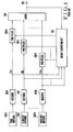
- the coherent sidelobe canceller employs a digital open-loop configuration for sidelobe cancellation computational processing.
- This sidelobe canceller is configured as a linear array antenna system including signal receiving means having (N + 1) channels (N is an integer more than one) comprising a main antenna 200, N auxiliary antennas 210-1 to 210-N, and (N + 1) receiver circuits connected to (N + 1) antennas with a one-to-one relationship, thereby to produce radar video signals from receiver circuits, respectively.
- This sidelobe cancellation system further comprises (N + 1) analogue-to-digital (A/D) convertors 220-0 to 220-N having inputs connected to outputs of the receiver circuits, respectively, to convert radar video signals to corresponding digital signals, (N + 1) memories 230-0 to 230-N having inputs connected to outputs of the A/D converters, respectively, to store digital signals therein until weighting coefficient computational processing to be referred to later is completed.
- N + 1 analogue-to-digital (A/D) convertors 220-0 to 220-N having inputs connected to outputs of the receiver circuits, respectively, to convert radar video signals to corresponding digital signals
- N + 1 memories 230-0 to 230-N having inputs connected to outputs of the A/D converters, respectively, to store digital signals therein until weighting coefficient computational processing to be referred to later is completed.
- This sidelobe cancellation system further comprises (N + 1) multipliers 240 to 24N having inputs connected to the memories 230 to 23N and a weighting coefficient computing circuit which will be described soon to start readout operation from memories 230 to 23N upon completion of the weighting coefficient calculation, thereby to multiply a weighting coefficient calculated by digital signals thus read, and a summer 250 for respective outputs from multipliers 240 to 24N and having an output terminal 290 from which summed value is output.
- weighting coefficient computational circuitry receives all outputs of A/D converters 220-0 to 220-N to perform statistical calculation processing with respect to time series digital signals, thus calculating weighting coefficients based on statistical characteristic of the received signal.
- This circuitry comprises a clutter region detector circuit 260 having an output connected to the output of the A/D converter 220-0 (corresponding to the channel CH o ) to determine a clutter region in the received signal 1, a covariance matrix computing circuit 270 having inputs connected to the output of the clutter region detector circuit 260 and the outputs of the A/D converters 220-1 to 220-N (corresponding to the channels CH, to CH N ) to produce information indicative of the covariance matrix ⁇ .
- a signal coming into a radar and received by the main antenna 200-0 and the auxiliary antennas 200-1 to 200-N is transmitted to the receiver circuits 210-0 to 210-N to provide a plurality of radar video signals.
- the plurality of radar video signals are converted to a plurality of digital signals by the analog-to-digital (A/D) converters 220-0 to 220-N, respectively.
- A/D analog-to-digital
- T is referred to as a sampling interval in performing A/D conversion
- output signals X 0 (l T ) to X N (l T ) are fed to the memories 230-0 to 230-N and at the same time to the covariance matrix computation circuit 270.
- the output X O (l T ) is fed to the clutter region detector circuit 260 so as to be used for determining a clutter region.
- the covariance matrix computation circuit 270 is responsive to the clutter region signal from the clutter region detector circuit 260 to calculate the covariance matrix (p from generally K digital data outside the clutter region by using the following equation:
- the weighting coefficient computation circuit 280 first effects an inverse matrix operation ⁇ -1 expressed by the equation (6) and thereafter calculates weight coefficient W from the equations (2) and (3).
- the adder 250 performs the following.calculation to calculate an output signal y(l T ).
- the weight coefficient W 1 is expressed as below when the constant is selected so that W o equals 1 (one).
- the coherent sidelobe canceller of the foregoing embodiment is constituted as a linear array antenna system having digital open-loop configuration for sidelobe cancellation processing.
- the sidelobe cancellation system can eliminate the necessity of repetitive calculation which must be used in the prior art sidelobe canceller based on a closed-loop control, thus allowing the present system to be free from the convergence time problem.
- the present system is designed so as to delay a received signal by a processing time required for weighting coefficient calculation using a memory so that both timings of the received signal and the weighting coefficient are equal to each other. For this reason, with the present system, there is no possibility that a processing time delay occurs, thus making it possible to prevent interference suppression capability from being degraded.
- the present system is provided with means for detecting a clutter region, thereby to completely remove undesired phenomena caused by a clutter signal which would be mixed during the execution of weighting coefficient processing, which could not be avoided with both the prior art systems.
- the present invention makes it possible to calculate a theoretically optimum weight coefficient solely using a radar received signal wherein the computation time required therefore depends upon the number N of auxiliary antennas.
- the present invention stores received input signals in memories during a time required for weighting coefficient calculation to read out them from the memories upon completion of the weighting coefficient calculation, thereby to implement coherent sidelobe processing thereof using the calculated weighting coefficient. Accordingly, there arises no problem in respect of computational processing time.
- the theoretically optimum weight coefficient can be applied without processing delay. Further, the undesired influence of clutter can be avoided to provide an improved interference signal suppression capability.
Description
- The present invention relates to a coherent sidelobe canceller for eliminating interference signals in a radar system, as set forth in the introduction part of claim 1.
- Sidelobe cancellers for radar consist of a main, high gain antenna and a plurality of auxiliary antennas each having a gain corresponding to a sidelobe gain of the main antenna and a beam width broader than that of the main antenna. In the sidelobe canceller, signals received from the main- and auxiliary-antennas are linearly coupled by making use of correlation between the main- and auxiliary- antennas in regard to interference signals coming from sidelobe regions of the main antenna to form a certain pattern in the arrival direction of the interference signals, thus suppressing interference waves.
- Referring to Fig. 1, there is shown a typical arrangement of a conventional sidelobe canceller. The sidelobe canceller is configured as a linear array antenna system having (N + 1) channels CHo to, CHN, comprising a main antenna 100-0, a plurality of auxiliary antennas 100-1 to 100-N, receiver circuits 110-0 to 110-N for receiving signals coming from the main- and auxiliary antennas, respectively, to produce radar video signals, a
weight computing circuit 120 which effects a weighting operation in response to (N + 1) radar video signals to produce desired weights, multipliers 130-0 to 130-N for multiplying radar video signals from receivers 110-0 to 110-N by weight outputs from theweight computing circuit 120, and anadder 140 for summing respective outputs from the multipliers to produce a summed signal on anoutput terminal 150. - The function of such a coherent sidelobe canceller will be described using a mathematical representation. Assuming now that an input signal of the main antenna is denoted by Xo(t), the number of the auxiliary antennas is N, the input signal of the i-th auxiliary antenna is x,(t), and the weighting coefficient for each i-th input terminal WI, an output signal y(t) is expressed as

- It has been known that the value of the optimum weighting coefficient for maximizing the suppression of the interference signals coming from sidelobe regions of the main antenna is theoretically obtained by


- Further, the covariance matrix is expressed by, with E being referred to as an expectation value operator,

- (1) Since the equation (2) is obtained by performing complex operation, the operational time required for obtaining the inverse matrix φ.-1 increases exponentially as N increases.
- (2) It is required to perform the expectation value operation over sufficiently long time in a time range within which the characteristics of interference signals do not vary, thus ensuring a predetermined statistical operational processing accuracy. However, if the operational processing for the expectation value is effected for long time, the delay in processing increases, resulting in degradation of response speed with respect to the interference.
- For this reason, in the prior art, a technique for calculating the weighting coefficient due to repetitive operation in an asymptotic manner has been widely used. This technique is expressed by, with the repetitive number being as a subscript,

- (1) Because of repetitive operation, a time for convergence is required, imposing a limitation on the response speed with respect to interferences, thus giving rise to a large impact in practice in a radar requiring instantaneous response.
- (2) In a radar, there generally exist reflected signals (which will be called "clutter" hereinafter) from mountains, buildings, rainy clouds, the sea level etc., as well as interference signals. During repetitive processing, if clutter signal components are contained in an input signal, they will vary as time elapses to make the operation based on the equation (4) invalid, thus failing to obtain the desired interference suppression capability.
- Further information in connection with the above technique for obtaining weight coefficient by repetitive operation is given by e.g. IEEE Trans. Antennas and Propag. AP-24: 585-598 (1976) pp 136-149. This describes sidelobe cancellation based on closed-loop processing similar to the above Fig. 1 system. This system carries out weighting coefficient calculation by repetitive operational processing based on a feedback closed-loop. Accordingly, in the application of a radar where instantaneous response is required, there is a tendency that the convergence time increases. Further, since this system is unable to reject or eliminate clutter signals, the clutter signal is included in the weighting coefficient computational processing in the vicinity of the clutter region, resulting in difficulty in suppressing interference signals. Furthermore, in the event that there occurs interference in a clutter region, the clutter signal is included in the feedback loop, thus making it difficult to suppress interference signals.
- On the other hand, another prior art interference canceller is disclosed in PROC IEE Vol. 130. Pts. F and H. No. 1. Feb. 1983. This system is based on an open-loop control. Viz., the latter system employs a weighting coefficient calculation due to digital open-loop processing, requiring about 10 to TOO samples for maintaining a desired calculation accuracy. This results in a delay in processing to cause a time difference between the received signal and the weighting coefficient, thus degrading interference signal suppression performance. Namely, there is no function to delay the received signal by a processing delay due to weighting coefficient computational processing. Further, since similar to the former close-loop system, there is no function for rejecting clutter signals, the clutter signal is included in the weighting coefficient computational processing in the vicinity of the clutter region, thus making it difficult to suppress interference signals. Furthermore, an interference signal is likely to be superposed on a clutter signal in the clutter region, leading to difficulty in suppressing the interference signal.
- A canceller in accordance with the introductory part of claim 1 is known from EP-A-0 068 909 in which interference (jamming) is detected using a signal from which ground clutter has been removed by MTI (moving target indication). Weighting coefficients are then calculated using signals derived from jammed range cells where the jamming exists.
- The object of the present invention is to prevent erroneous calculation of weighting coefficients due to clutter signal components in a simple manner.
- The canceller according to the invention is characterised in the manner set forth in claim 1.
- The coherent sidelobe canceller delays the received signals by making use of the memories during the processing time required for weighting coefficient calculation, thereby allowing the response time to be substantially zero, thus improving interference signal suppression capability.
- Another object of the present invention is to provide a coherent sidelobe canceller which detects a clutter region to sample only signals other than those in clutter regions thereby to effect weighting coefficient operational processing, thus enabling suppression of interference signals without undesired influence of the clutter.
- In a preferred implementation of the present invention, the coherent sidelobe canceller comprises means for determining from a received signal of a radar a region in which there is no clutter, means responsive to the first mentioned means to calculate a covariance matrix of the received signal of the radar on the basis of the equation (4) by making use of, among time series received signals, a signal existing in a region in which there is no clutter, means for computing a theoretically optimum weight coefficient from the calculated coveriance matrix using the equation (2), and a memory for storing the radar received signal during the time required for calculating the weight coefficient, whereby the weight coefficient calculated by the equation (2) is applied to the received signal read from the memory used for calculating the covariance of the equation (4) and real time processing is realized without response delay with respect to interference by effecting the coherent sidelobe operational processing based on equation (1).
- The features and advantages of a coherent sidelobe canceller according to the present invention will become apparent from the following description taken in conjunction with the accompanying drawings, in which:
- Fig. 1 is a block diagram illustrating a typical construction of a conventional coherent sidelobe canceller, as described above, and
- Fig. 2 is a block diagram illustrating a coherent sidelobe canceller according to an embodiment of the present invention.
- The present invention will be described with reference to Fig. 2 illustrating an embodiment thereof.
- As shown in Fig. 2, the coherent sidelobe canceller according to the present invention employs a digital open-loop configuration for sidelobe cancellation computational processing. This sidelobe canceller is configured as a linear array antenna system including signal receiving means having (N + 1) channels (N is an integer more than one) comprising a
main antenna 200, N auxiliary antennas 210-1 to 210-N, and (N + 1) receiver circuits connected to (N + 1) antennas with a one-to-one relationship, thereby to produce radar video signals from receiver circuits, respectively. - This sidelobe cancellation system further comprises (N + 1) analogue-to-digital (A/D) convertors 220-0 to 220-N having inputs connected to outputs of the receiver circuits, respectively, to convert radar video signals to corresponding digital signals, (N + 1) memories 230-0 to 230-N having inputs connected to outputs of the A/D converters, respectively, to store digital signals therein until weighting coefficient computational processing to be referred to later is completed.
- This sidelobe cancellation system further comprises (N + 1)
multipliers 240 to 24N having inputs connected to thememories 230 to 23N and a weighting coefficient computing circuit which will be described soon to start readout operation frommemories 230 to 23N upon completion of the weighting coefficient calculation, thereby to multiply a weighting coefficient calculated by digital signals thus read, and asummer 250 for respective outputs frommultipliers 240 to 24N and having an output terminal 290 from which summed value is output. - In addition to the components stated above, the present sidelobe cancellation system is provided with weighting coefficient computational circuitry. This weighting coefficient computational circuitry receives all outputs of A/D converters 220-0 to 220-N to perform statistical calculation processing with respect to time series digital signals, thus calculating weighting coefficients based on statistical characteristic of the received signal. This circuitry comprises a clutter
region detector circuit 260 having an output connected to the output of the A/D converter 220-0 (corresponding to the channel CHo) to determine a clutter region in the received signal 1, a covariancematrix computing circuit 270 having inputs connected to the output of the clutterregion detector circuit 260 and the outputs of the A/D converters 220-1 to 220-N (corresponding to the channels CH, to CHN) to produce information indicative of the covariance matrix φ. The weighting coefficient computational circuitry further comprises a weightingcoefficient computing circuit 280 having an input connected to the output of the covariancematrix computing circuit 270 to calculate an inverse matrix φ-1 of the covariance matrix input thereto, thus calculating a weighting coefficient vector W on the basis of the relationship expressed as W = µφ-1S* where p is an arbitrary constant and S* is an arbitrary vector. - In operation, a signal coming into a radar and received by the main antenna 200-0 and the auxiliary antennas 200-1 to 200-N is transmitted to the receiver circuits 210-0 to 210-N to provide a plurality of radar video signals. The plurality of radar video signals are converted to a plurality of digital signals by the analog-to-digital (A/D) converters 220-0 to 220-N, respectively. Assume now that T is referred to as a sampling interval in performing A/D conversion and Xo(lT) to XN(lT) (I = 1, 2, ... M) are referred to as output signals of the A/D converters, respectively. These output signals X0(lT) to XN(lT) are fed to the memories 230-0 to 230-N and at the same time to the covariance
matrix computation circuit 270. The output XO(lT) is fed to the clutterregion detector circuit 260 so as to be used for determining a clutter region. The covariancematrix computation circuit 270 is responsive to the clutter region signal from the clutterregion detector circuit 260 to calculate the covariance matrix (p from generally K digital data outside the clutter region by using the following equation:
- The weighting
coefficient computation circuit 280 first effects an inverse matrix operation φ-1 expressed by the equation (6) and thereafter calculates weight coefficient W from the equations (2) and (3). - The multipliers 240-0 to 240-N multiply Wo to WN, given by the weighting
coefficient computation circuit 280, by digital data Xo(lT) to XN(IT) respectively read from the corresponding memories to calculate WOXO(IT1 to XNXN(lT) (I = 1, 2, ... M). - Finally, the
adder 250 performs the following.calculation to calculate an output signal y(lT).
- In a particular case where the number of auxiliary antennas is one (N = 1), as a result of the above calculations, the weight coefficient W1 is expressed as below when the constant is selected so that Wo equals 1 (one).

- As readily appreciated from the foregoing description, the coherent sidelobe canceller of the foregoing embodiment is constituted as a linear array antenna system having digital open-loop configuration for sidelobe cancellation processing.
- Accordingly, the sidelobe cancellation system according to this embodiment can eliminate the necessity of repetitive calculation which must be used in the prior art sidelobe canceller based on a closed-loop control, thus allowing the present system to be free from the convergence time problem.
- Further, even if compared to another prior art system based on a digital open-loop control which could be considered to be closer to the present system than the first mentioned closed-loop system, there is clear difference therebetween in that the present system is designed so as to delay a received signal by a processing time required for weighting coefficient calculation using a memory so that both timings of the received signal and the weighting coefficient are equal to each other. For this reason, with the present system, there is no possibility that a processing time delay occurs, thus making it possible to prevent interference suppression capability from being degraded.
- Furthermore, the present system is provided with means for detecting a clutter region, thereby to completely remove undesired phenomena caused by a clutter signal which would be mixed during the execution of weighting coefficient processing, which could not be avoided with both the prior art systems.
- As stated above, the present invention makes it possible to calculate a theoretically optimum weight coefficient solely using a radar received signal wherein the computation time required therefore depends upon the number N of auxiliary antennas. The present invention stores received input signals in memories during a time required for weighting coefficient calculation to read out them from the memories upon completion of the weighting coefficient calculation, thereby to implement coherent sidelobe processing thereof using the calculated weighting coefficient. Accordingly, there arises no problem in respect of computational processing time. In addition to this, the theoretically optimum weight coefficient can be applied without processing delay. Further, the undesired influence of clutter can be avoided to provide an improved interference signal suppression capability.
Claims (2)
Applications Claiming Priority (2)
| Application Number | Priority Date | Filing Date | Title |
|---|---|---|---|
| JP58195743A JPH06100647B2 (en) | 1983-10-19 | 1983-10-19 | Coherent side rob canceller |
| JP195743/83 | 1983-10-19 |
Publications (3)
| Publication Number | Publication Date |
|---|---|
| EP0142293A2 EP0142293A2 (en) | 1985-05-22 |
| EP0142293A3 EP0142293A3 (en) | 1986-09-24 |
| EP0142293B1 true EP0142293B1 (en) | 1990-12-27 |
Family
ID=16346227
Family Applications (1)
| Application Number | Title | Priority Date | Filing Date |
|---|---|---|---|
| EP84307204A Expired EP0142293B1 (en) | 1983-10-19 | 1984-10-19 | Coherent sidelobe canceller for radar |
Country Status (4)
| Country | Link |
|---|---|
| US (1) | US4577193A (en) |
| EP (1) | EP0142293B1 (en) |
| JP (1) | JPH06100647B2 (en) |
| DE (1) | DE3483874D1 (en) |
Cited By (1)
| Publication number | Priority date | Publication date | Assignee | Title |
|---|---|---|---|---|
| US6006110A (en) * | 1995-02-22 | 1999-12-21 | Cisco Technology, Inc. | Wireless communication network using time-varying vector channel equalization for adaptive spatial equalization |
Families Citing this family (25)
| Publication number | Priority date | Publication date | Assignee | Title |
|---|---|---|---|---|
| US4720712A (en) * | 1985-08-12 | 1988-01-19 | Raytheon Company | Adaptive beam forming apparatus |
| BE1012743A4 (en) * | 1986-04-23 | 2001-03-06 | Dassault Electronique Soc Comm | Interferometric receiver of electromagnetic signals. |
| FR2749399B2 (en) * | 1986-11-19 | 1999-03-05 | Dassault Electronique | INTERFEROMETRIC RECEIVER WITH GENERALIZED GAIN CONTROL |
| US4736460A (en) * | 1986-11-10 | 1988-04-05 | Kenneth Rilling | Multipath reduction system |
| FR2723209B1 (en) * | 1987-07-08 | 1997-04-30 | Dassault Electronique | DEVICE FOR THE ECARTOMETRY OF FOUR CONFUSION INTERFERERS |
| GB8809630D0 (en) * | 1988-04-23 | 1988-10-05 | Plessey Co Plc | Radar systems |
| JPH02227687A (en) * | 1989-02-28 | 1990-09-10 | Nec Corp | Coherent side lobe canceler |
| US5105814A (en) * | 1990-08-15 | 1992-04-21 | Hewlett-Packard Company | Method of transforming a multi-beam ultrasonic image |
| US5273602A (en) * | 1990-12-19 | 1993-12-28 | Hercules Incorporated | Ribbonizing method for selectively heating a respective one of a plurality of fiber tows |
| US5491487A (en) * | 1991-05-30 | 1996-02-13 | The United States Of America As Represented By The Secretary Of The Navy | Slaved Gram Schmidt adaptive noise cancellation method and apparatus |
| JP2684888B2 (en) * | 1991-08-06 | 1997-12-03 | 国際電信電話株式会社 | Adaptive array antenna control method |
| US5274386A (en) * | 1992-06-17 | 1993-12-28 | General Electric Co. | Reduced hardware antenna beamformer |
| US5339284A (en) * | 1992-07-17 | 1994-08-16 | Frederick Herold & Associates, Inc. | Signal processor for elimination of sidelobe responses and generation of error signals |
| US5448247A (en) * | 1992-12-15 | 1995-09-05 | National Space Development Agency Of Japan | Beam compression method for radar antenna patterns |
| JP2544299B2 (en) * | 1993-05-10 | 1996-10-16 | 宇宙開発事業団 | Beam compression processing method of antenna pattern in radar |
| US5434578A (en) * | 1993-10-22 | 1995-07-18 | Westinghouse Electric Corp. | Apparatus and method for automatic antenna beam positioning |
| US6101399A (en) * | 1995-02-22 | 2000-08-08 | The Board Of Trustees Of The Leland Stanford Jr. University | Adaptive beam forming for transmitter operation in a wireless communication system |
| US7286855B2 (en) | 1995-02-22 | 2007-10-23 | The Board Of Trustees Of The Leland Stanford Jr. University | Method and apparatus for adaptive transmission beam forming in a wireless communication system |
| AU4896697A (en) | 1996-10-18 | 1998-05-15 | Watkins-Johnson Company | Wireless communication network using time-varying vector channel equalization for adaptive spatial equalization |
| US5760734A (en) * | 1996-11-18 | 1998-06-02 | Lockheed Martin Corp. | Radar clutter removal by matrix processing |
| EP0899896A1 (en) * | 1997-08-27 | 1999-03-03 | Siemens Aktiengesellschaft | Method and system to estimate spatial parameters of transmission channels |
| US6600446B2 (en) | 2001-06-29 | 2003-07-29 | Lockheed Martin Corporation | Cascadable architecture for digital beamformer |
| JP4723910B2 (en) * | 2005-05-30 | 2011-07-13 | 株式会社東芝 | Radar equipment |
| US9250313B2 (en) * | 2013-12-04 | 2016-02-02 | Raytheon Company | Electronically reconfigurable bandwidth and channel number analog-to-digital converter circuit for radar systems |
| JP7412933B2 (en) * | 2019-09-17 | 2024-01-15 | 株式会社東芝 | radar equipment |
Family Cites Families (4)
| Publication number | Priority date | Publication date | Assignee | Title |
|---|---|---|---|---|
| US4313116A (en) * | 1980-01-30 | 1982-01-26 | Westinghouse Electric Corp. | Hybrid adaptive sidelobe canceling system |
| NL8005725A (en) * | 1980-10-17 | 1982-05-17 | Hollandse Signaalapparaten Bv | METHOD AND APPARATUS FOR SUPPLYING FAULT SIGNALS FROM FAULT SOURCES DURING THE RECEPTION OF TARGET SECO SIGNALS IN THE RECEIVER OF AN IMPULSE RADAR DEVICE. |
| GB2089614B (en) * | 1980-12-15 | 1984-11-07 | Marconi Co The Ltd | An improved side lobe canceller for radar systems |
| FR2505052A1 (en) * | 1981-04-30 | 1982-11-05 | Thomson Csf | METHOD AND DEVICE FOR REDUCING THE POWER OF THE INTERFERENCE SIGNALS RECEIVED BY THE SECONDARY LOBES OF A RADAR ANTENNA |
-
1983
- 1983-10-19 JP JP58195743A patent/JPH06100647B2/en not_active Expired - Lifetime
-
1984
- 1984-10-18 US US06/663,464 patent/US4577193A/en not_active Expired - Lifetime
- 1984-10-19 DE DE8484307204T patent/DE3483874D1/en not_active Expired - Lifetime
- 1984-10-19 EP EP84307204A patent/EP0142293B1/en not_active Expired
Cited By (1)
| Publication number | Priority date | Publication date | Assignee | Title |
|---|---|---|---|---|
| US6006110A (en) * | 1995-02-22 | 1999-12-21 | Cisco Technology, Inc. | Wireless communication network using time-varying vector channel equalization for adaptive spatial equalization |
Also Published As
| Publication number | Publication date |
|---|---|
| EP0142293A2 (en) | 1985-05-22 |
| JPH06100647B2 (en) | 1994-12-12 |
| DE3483874D1 (en) | 1991-02-07 |
| JPS6088375A (en) | 1985-05-18 |
| US4577193A (en) | 1986-03-18 |
| EP0142293A3 (en) | 1986-09-24 |
Similar Documents
| Publication | Publication Date | Title |
|---|---|---|
| EP0142293B1 (en) | Coherent sidelobe canceller for radar | |
| US5371506A (en) | Simultaneous multibeam approach for cancelling multiple mainlobe jammers while preserving monopulse angle estimation accuracy on mainlobe targets | |
| US5796779A (en) | Adaptive signal processor for non-stationary environments and method | |
| US5600326A (en) | Adaptive digital beamforming architecture and algorithm for nulling mainlobe and multiple sidelobe radar jammers while preserving monopulse ratio angle estimation accuracy | |
| US5349567A (en) | Least mean square (LMS) normalizer for active sonar | |
| US6867726B1 (en) | Combining sidelobe canceller and mainlobe canceller for adaptive monopulse radar processing | |
| US4849764A (en) | Interference source noise cancelling beamformer | |
| US4086592A (en) | Digital sidelobe canceller | |
| JP2009162613A (en) | Radar system | |
| CA2047813C (en) | Acceleration compensation by matched filtering | |
| US4573052A (en) | Method and device for reducing the power of jamming signals received by the sidelobes of a radar antenna | |
| US5361074A (en) | Mainlobe canceller system | |
| EP0187851B1 (en) | Adaptive predictor of surface reverberation in a bistatic sonar | |
| CN101726730A (en) | Self-adaption anti-coherent interference technology based on characteristic component rejection | |
| US4222051A (en) | Cascaded digital cancelers | |
| Ward et al. | Application of a systolic array to adaptive beamforming | |
| EP0050384A1 (en) | Elimination in a pulse radar receiver of interference signals stemming from N distinct sources | |
| EP1070365A2 (en) | System for canceling interferers from broadband active sonar signals using adaptive beamforming methods | |
| Vijaykumar Mahamuni | Space-time adaptive processing techniques (STAP) for mitigation of jammer interference and clutter suppression in airborne radar systems: A MATLAB implementation-based study | |
| US4727375A (en) | Process for adapting the post integration in a switched pulse repetition frequency radar and a circuit implementing this process | |
| US6366239B1 (en) | Phase stabilization in adaptive arrays | |
| EP0054982B1 (en) | Threshold circuit for radar video data | |
| Mahamuni | Space-Time Adaptive Processing (STAP) Techniques for Mitigation of Jammer Interference and Clutter Suppression in Airborne Radar Systems: A MATLAB Implementation-Based Study | |
| EP0096144B1 (en) | System for the cancellation of intentional disturbance applied to a monopulse phased array radar | |
| Brown et al. | Algorithm development for an airborne real-time STAP demonstration |
Legal Events
| Date | Code | Title | Description |
|---|---|---|---|
| PUAI | Public reference made under article 153(3) epc to a published international application that has entered the european phase |
Free format text: ORIGINAL CODE: 0009012 |
|
| 17P | Request for examination filed |
Effective date: 19841031 |
|
| AK | Designated contracting states |
Designated state(s): DE FR GB |
|
| PUAL | Search report despatched |
Free format text: ORIGINAL CODE: 0009013 |
|
| AK | Designated contracting states |
Kind code of ref document: A3 Designated state(s): DE FR GB |
|
| 17Q | First examination report despatched |
Effective date: 19880517 |
|
| GRAA | (expected) grant |
Free format text: ORIGINAL CODE: 0009210 |
|
| AK | Designated contracting states |
Kind code of ref document: B1 Designated state(s): DE FR GB |
|
| REF | Corresponds to: |
Ref document number: 3483874 Country of ref document: DE Date of ref document: 19910207 |
|
| ET | Fr: translation filed | ||
| PLBE | No opposition filed within time limit |
Free format text: ORIGINAL CODE: 0009261 |
|
| STAA | Information on the status of an ep patent application or granted ep patent |
Free format text: STATUS: NO OPPOSITION FILED WITHIN TIME LIMIT |
|
| 26N | No opposition filed | ||
| REG | Reference to a national code |
Ref country code: GB Ref legal event code: IF02 |
|
| PGFP | Annual fee paid to national office [announced via postgrant information from national office to epo] |
Ref country code: FR Payment date: 20031003 Year of fee payment: 20 |
|
| PGFP | Annual fee paid to national office [announced via postgrant information from national office to epo] |
Ref country code: GB Payment date: 20031016 Year of fee payment: 20 |
|
| PGFP | Annual fee paid to national office [announced via postgrant information from national office to epo] |
Ref country code: DE Payment date: 20031030 Year of fee payment: 20 |
|
| PG25 | Lapsed in a contracting state [announced via postgrant information from national office to epo] |
Ref country code: GB Free format text: LAPSE BECAUSE OF EXPIRATION OF PROTECTION Effective date: 20041018 |
|
| REG | Reference to a national code |
Ref country code: GB Ref legal event code: PE20 |