EP0141089A2 - Apparatus for the selective determination of the components of gaseous mixtures - Google Patents
Apparatus for the selective determination of the components of gaseous mixtures Download PDFInfo
- Publication number
- EP0141089A2 EP0141089A2 EP84109652A EP84109652A EP0141089A2 EP 0141089 A2 EP0141089 A2 EP 0141089A2 EP 84109652 A EP84109652 A EP 84109652A EP 84109652 A EP84109652 A EP 84109652A EP 0141089 A2 EP0141089 A2 EP 0141089A2
- Authority
- EP
- European Patent Office
- Prior art keywords
- sensor elements
- gas
- sensor
- heat
- temperature
- Prior art date
- Legal status (The legal status is an assumption and is not a legal conclusion. Google has not performed a legal analysis and makes no representation as to the accuracy of the status listed.)
- Withdrawn
Links
Images


Classifications
-
- G—PHYSICS
- G01—MEASURING; TESTING
- G01N—INVESTIGATING OR ANALYSING MATERIALS BY DETERMINING THEIR CHEMICAL OR PHYSICAL PROPERTIES
- G01N27/00—Investigating or analysing materials by the use of electric, electrochemical, or magnetic means
- G01N27/02—Investigating or analysing materials by the use of electric, electrochemical, or magnetic means by investigating impedance
- G01N27/04—Investigating or analysing materials by the use of electric, electrochemical, or magnetic means by investigating impedance by investigating resistance
- G01N27/12—Investigating or analysing materials by the use of electric, electrochemical, or magnetic means by investigating impedance by investigating resistance of a solid body in dependence upon absorption of a fluid; of a solid body in dependence upon reaction with a fluid, for detecting components in the fluid
-
- G—PHYSICS
- G01—MEASURING; TESTING
- G01N—INVESTIGATING OR ANALYSING MATERIALS BY DETERMINING THEIR CHEMICAL OR PHYSICAL PROPERTIES
- G01N33/00—Investigating or analysing materials by specific methods not covered by groups G01N1/00 - G01N31/00
- G01N33/0004—Gaseous mixtures, e.g. polluted air
- G01N33/0009—General constructional details of gas analysers, e.g. portable test equipment
- G01N33/0027—General constructional details of gas analysers, e.g. portable test equipment concerning the detector
- G01N33/0031—General constructional details of gas analysers, e.g. portable test equipment concerning the detector comprising two or more sensors, e.g. a sensor array
Definitions
- the invention relates to a device for the selective determination of the constituents of gas mixtures of the type defined in the preamble of claim 1.
- Gas sensors have been used for various purposes such as Environmental protection, garage monitoring, fire protection and explosion protection are used. For this purpose, cheap sensors made of metal oxides are used, the electrical conductivity of which depends on the concentration of the gases to be detected in the surrounding air. The concentration of gas to be detected can be inferred from the change in the electrical conductivity. To carry out gas detection with these sensors, the sensor must be brought to a temperature of approx. 450 ° C.
- the known gas sensors consist of finely ground metal oxide powder which is sintered onto a carrier provided with electrodes and have only a very low selectivity in their gas detection. The values obtained with these gas sensors do not allow any conclusions to be drawn as to which gas component within a gas mixture.
- the gas sensors that a different sensitivity to the constituents of the gas mixture comprise it is desirable to obtain information on the nature of the gas.
- a common interfering gas is ethyl alcohol vapor, which occurs frequently in kitchens etc., since the gas sensors that are sensitive to carbon monoxide and hydrocarbons also respond to ethyl alcohol vapor.
- a gas sensor was therefore proposed in which three gas sensors made of different materials are provided, two of which are used to detect methane (main component in natural gas), hydrogen and / or carbon monoxide (components in city gas and due to incomplete ones Combustion). Since both sensor elements also respond to alcohol vapor, the concentration of alcohol vapor is measured with a third gas sensor that specifically reacts to ethyl alcohol vapor, and this value is subtracted from the concentrations of methane and carbon monoxide determined with the other two sensor elements.
- This gas detector has the disadvantage that it only reacts to two components of gas mixtures, whereby it can exclude another specific component as a disruptive factor.
- the present invention has for its object to provide a device of the type mentioned, which avoids the disadvantages of the known devices and allows a selective determination of different components of gas mixtures.
- the sensor elements and the given if existing heating devices are arranged so that the gas mixture to be examined is directed past the sensor elements with a directed current.
- a gas-tight layer can be provided for this purpose, which directs the gas mixture to be examined such that it preferably sweeps over the sensor elements one after the other.
- the sensor elements have a different operating temperature, the sensor element lying in front in the direction of the gas flow preferably having a lower temperature than the sensor element behind it.
- the sensor elements can also be arranged in a coherent block, a temperature gradient being present in the direction of the gas flow, i.e. the temperature gradually increases in the direction of the gas flow. Electrodes are arranged in series on the sensor block, each corresponding to a different temperature range. Different gases are detected on differently hot parts of the sensor block, the change in conductivity being supplied to the evaluation circuit by the corresponding assigned electrodes.
- the sensor elements 5 of the gas sensors 6 are made of a material 1 which is described in the Swiss patents N r. (Patent Application 4737 / 83-9) and (Patent Application No. 4738 / 83-0) and which is also commercially available.
- FIG. 1 shows a cross section through a gas sensor 6 at a point at which a sensor element 5 is arranged.
- the gas sensor 6 has several such sensor elements 5.
- the material 1, which changes its electrical conductivity when exposed to gases, is connected at its ends to two electrodes 4, which are connected via electrical lines 11 to an evaluation circuit, not shown.
- the heating device 8, which is arranged between two insulating layers 7 and 9, is located below the material 1.
- the heating device 8 can consist of conventional heating wires or be a layer of platinum, iridium or their alloys with a large temperature coefficient of electrical conductivity, so that the heating temperature can be determined simultaneously by measuring the resistance of the heating device.
- the material 1 of the sensor element 5 is heated to a predetermined operating temperature by this heating device.
- the individual sensor elements 5 are arranged on a heat-resistant, heat-insulating substrate 10 and together form the gas sensor 6.
- the gas sensor 6 can be located in a housing, not shown, which is attached to the location to be monitored.
- the heating device 8 is connected to a power source via lead wires, not shown.
- Switching elements are provided in the evaluation circuit, which ensure that the predetermined operating temperature, which can be in the range from room temperature to 450 ° C., is set and kept constant.
- the various sensor elements 5 which consist of the same or different materials are set to the same operating temperature, or each of the sensor elements 5 can be heated to a different temperature in the range mentioned for the detection of different constituents of gas mixtures.
- the dimensions of the components are kept as small as possible. Since the sensor elements 5 are not suspended from the lead wires as in the case of the gas sensors of the prior art, but rather are located on the stable, heat-resistant, heat-insulating substrate 10, the lead wires can have a very small cross section. For example, a diameter of 30 ⁇ m is completely sufficient, which further reduces heat dissipation.
- the spatial dimensions of the gas sensor 6 of Figure 1 is 5 mm in height, 3 mm in width and 3 mm in length. Because of these extremely small dimensions, the gas sensors can also be installed in places that are difficult to access.
- a single sensor element 5 is sufficient, which is arranged with its heating device 8 located between two electrically insulating layers 7 and 9 on a heat-resistant, heat-insulating substrate 10.
- the heating device 8 brings the material 1 of the gas sensor 6 to a temperature which is optimally matched for the detection of the one dangerous gas.
- the use of the heat-insulating substrate 10 makes the operation of such a gas sensor 6 according to the invention very economical, since only a low heating power is required, which is only about 300 mW at a temperature of the material 1 of 360 ° C.
- a gas sensor 6, which is shown in cross section in Figure 1 is drawn in plan view.
- the electrical lines 11 of the electrodes 4 are led to contact points 12, which are fastened on the insulation layer 7.
- the electrical contact points 12 are connected to the evaluation circuit via lines, not shown.
- the sensor elements 5 can all be heated to the same operating temperature by switching elements of the evaluation circuit or they can each have a different operating temperature. It is also possible to operate all sensor elements 5 at room temperature. Then the heating layer 8 and the electrically insulating layers 7 and 9 can be omitted.
- the electrical conductivities of the individual sensor elements 5 change depending on the concentration of the components.
- the sensitivity of the individual sensor elements 5 is adjusted to another component of the gas mixture.
- the materials 1 and the operating temperatures of the sensor elements 5 are set such that good selectivity between the individual components is ensured.
- the change in electrical conductivity that occurs at the electrodes 4 is measured via the electrical lines 11 in the evaluation circuit.
- the number of sensor elements 5 depends on the number of components that are to be determined in gas mixtures.
- the device shown in FIG. 2 is suitable, for example, for the detection of four different components.
- the sensitivity of a sensor element 5 can be set so that it responds to the interfering gas and the evaluation circuit can in this case be designed so that the concentration of the interfering gas is eliminated by calculation so that the desired component of the gas mixture can be determined can.
- FIG. 3 shows a top view of a further embodiment of a gas sensor 6, different sensor elements 5 being shown to explain the variety of possibilities in the individual areas. Because of the better clarity, only in the upper row of FIG Sensor elements 5 shown.
- each sensor element 5 has its own heating layer 8 and therefore separate electrically insulating layers 7 and 9 are also provided.
- the configuration of the other components is as stated above, ie the sensor elements 5 are located on a heat-resistant, heat-insulating substrate 10, the electrodes 4 are connected via electrical lines 11 to electrical contact points 12, which in turn are connected to an evaluation circuit via lines, not shown.
- the gas sensor 6 shown in Figure 3 twelve different gases can be detected.
- the number of sensor elements 5 can be adapted to the number of constituents of gas mixtures to be determined, ie they can be higher or lower.
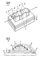
- FIG. 4 shows another gas sensor 6.
- a plurality of sensor elements 5 in the form of a cube have a hole in the center which passes through all sensor elements 5 and forms a tube. The air to be examined is passed through this tube and exits again at the end of the tube. The direction of flow is indicated by arrows.
- the sensor elements 5 change their electrical conductivity when the gas passing by their surface for which their response behavior has been optimized.
- Each sensor element 5 has electrodes 4 which are arranged such that they do not influence one another despite the compact arrangement of the sensor elements 5.
- the lines 11 connect the electrodes 11 to the contact points 12, which are attached to the electrically insulating layer 7 and are connected to an evaluation circuit.
- the arrangement mentioned is glued to the heat-resistant, heat-insulating substrate 10. With the gas sensor 6 of FIG. 4, more than just four gases can be detected if more sensor elements 5 are arranged accordingly.
- the sensor elements 5 can also be operated using an optical measurement method and can be electrically isolated from one another by thin layers.
- the entire block of sensor elements is enclosed by a gas-tight envelope, not shown in FIG. 4, with the exception of two openings at the two ends.
- a gas-tight envelope not shown in FIG. 4, with the exception of two openings at the two ends.
- This arrangement makes it possible to detect the constituents of a gas mixture on separate sensor elements 5 by changing their resistance.
- the electrodes 4 in FIG. 4 do not necessarily have to be attached to the outside, but can also be provided between the individual sensor elements 5.
- the gas sensor 6 shown in FIG. 4 can expediently be located at one end, e.g. at the inlet opening, have a lower temperature than at the outlet opening. Gases which already burn at low temperatures will then preferably burn on the first sensor element 5 and there will result in a large change in the electrical signals for the conductivity. Gases that only burn at higher temperatures will only burn on the second sensor element, gases that burn at even higher temperatures only on the third sensor element, etc. This enables the gases to be detected much more selectively. If the sensor elements are made of a highly porous metal oxide gel, e.g. consist of an airgel, so the middle hole is not even necessary. The design of FIG. 4 also relates to such cases.
- FIG. 5 shows a gas sensor 6, which consists of several pyramid-shaped sensor elements 5.
- the electrodes 4 are connected via electrical lines 11 to the electrical contact points 12 fastened on the heat-resistant, heat-insulating substrate 10, which are in turn connected to an evaluation circuit via connection lines (not shown).
- the electrodes 4 are insulated such that they are in contact only with the material 1 of the associated sensor element and not with the material 1 of the other sensor element.
- the outer walls of the sensor elements are partially provided with a gas-tight layer 14. Therefore, only the surfaces of the sensor elements lying on top are gas-active.
- the sensor elements are fastened on the electrically insulating layer 7, which is connected to the heating device 8 and the electrically insulating layer 9. The entire arrangement is fixed on the heat-resistant heat-insulating substrate 10.
- each sensor element is sensitized to a specific component of the gas mixture to be examined.
- the top sensor element is operated at room temperature. In this case, the top sensor element is thermally insulated from the other sensor elements.
- more sensor elements can be used for the gas sensor shown in FIG. 5. are drawn as in the figure.
- the contact points 12 in FIGS. 2 to 5 do not necessarily have to be on the electrically insulating layer 7, they can also be outside of this layer.
- FIG. 6 shows a longitudinal section and FIG. 7 shows a cross section through a gas sensor 6, which consists of a combination of several sensor elements that have a uniform material 1.
- the sensor element 5 is attached to the heating device 8 by an electrically insulating layer 7.
- the heating device 8 on the far left in FIG. 6 heats the zone of the sensor element 5 located above it, e.g. to 80 ° C.
- the next heating layer 8 on the right heats the zone of the sensor element 5 above e.g. 90 ° C etc.
- the sensor element 5 therefore has an increasing temperature from left to right.
- the individual heating layers 8 are attached to a heat-insulating substrate 10 by an electrically insulating layer 9.
- FIGS. 6 and 7 show a gas-tight layer 14 which encloses the layers 7, 8, 9 and the sensor element 5 in such a way that a free space remains above the sensor element 5.
- the air to be examined is directed through this free space from left to right, which is indicated by the arrow in FIG. 6.
- This air flow can be generated by a pump (not shown) or also by arranging the entire gas sensor 6 vertically, the heating device 8 with the lowest temperature being at the bottom. Due to the chimney effect, an air flow will set itself up.
- FIG. 7 also shows the electrical lines 11 which lead through the gas-tight layer 14 to the evaluation circuit. Easily oxidizable gases will now burn on the far left, at low temperature, and there will result in large changes in the electrical resistance of the sensor element 5. Gases that are more difficult to oxidize are, for example, only in the middle of the gas sensor 6 at a medium temperature burn temperature and there result a large change in the electrical resistance at the sensor element 5. Gases that are very difficult to oxidize, on the other hand, will only react at the right, hot end of the gas sensor 6 and cause a change in resistance at the sensor element 5 there. With this arrangement, a gas mixture can thus be broken down into its components and these components can be detected separately. A very high selectivity of the gas sensor is thus achieved, which can be increased considerably by suitable mathematical evaluation of the signals of the individual zones of the sensor element 5. Such an evaluation takes place in the evaluation circuit, not shown.
- FIG. 8 shows a longitudinal section and FIG. 9 shows a cross section through a further embodiment of a gas sensor 6, which contains several sensor elements 5, which consist of different material 1 and each contain two electrodes 4.
- These sensor elements 5 are brought to individual temperatures by separate heating layers 8, which are located between electrically insulating layers 7 and 9 and are fastened on a heat-insulating substrate 10.
- the leftmost sensor element 5 has e.g. a temperature of only 65 ° C.
- the next sensor element on the right has a temperature of 80 ° C.
- the next one has a temperature of 100 ° C etc.
- the sensor element on the far right has a temperature of 400 ° C.
- FIGS. 8 and 9 show a gas-tight layer 14 which surrounds the layers 7, 8, 9 and the sensor elements 5 in such a way that a free space remains open above the sensor elements 5.
- the air to be examined is directed through this free space from left to right, which is indicated by an arrow in FIG. 8.
- this, preferably laminar, Air flow is generated either by an external pump, not shown, or by the chimney effect, which occurs when the gas sensor 6 is arranged vertically, the sensor element with the lowest temperature being at the bottom.
- the electrical lines 11 lead through the gas-tight layer 14 to an evaluation circuit (not shown).
- the material 1 of the sensor element 5 is also selected (for example, it contains a special catalyst) in such a way that the easily oxidizable substances preferably burn on this sensor element, the oxidation being achieved by an optimal operating temperature, which is somewhat lower than that of the subsequent sensor element, and by a suitable chemical composition of the material 1 is strongly promoted. Since, in addition to the rising temperatures in the direction of the air flow, the chemical composition of the materials 1 of the sensor elements 5 is also optimally selected, the gaseous impurities in the air to be detected can be detected extremely selectively. A suitable mathematical combination of the signals from the individual sensor elements 5 can again greatly increase the selectivity of this gas sensor 6.
Abstract
Ein Gassensor (6), welcher mehrere Sensorelemente (5) enthält, die bei Einwirkung von Gasen ihre elektrische Leitfähigkeit ändern, kann zur selektiven Bestimmung der Bestandteile von Gasgemischen verwendet werden, wenn die einzelnen Sensorelemente (5) auf einem hitzebeständigen, wärmeisolierenden Substrat (10) angeordnet werden und die einzelnen Sensorelemente (5) durch die Wahl unterschiedlicher Materialien (1) und/oder der Betriebstemperatur zur Bestimmung unterschiedlicher Bestandteile des Gasgemischs sensibilisiert werden. Gemäss bevorzugten Ausführungsformen werden die Bauteile der Sensorelemente (5) so angeordnet, dass das zu untersuchende Gasgemisch in einem gerichteten Strom an den Sensorelementen (5) vorbeigeleitet wird. Durch eine abgestuft erhöhte Temperatur der Sensorelemente (5) in Richtung des Gasstroms kann einer weitere Steigerung der Selektivität des Gassensors (6) erreicht werden.A gas sensor (6), which contains several sensor elements (5) that change their electrical conductivity when exposed to gases, can be used for the selective determination of the components of gas mixtures if the individual sensor elements (5) are on a heat-resistant, heat-insulating substrate (10 ) are arranged and the individual sensor elements (5) are sensitized by the choice of different materials (1) and / or the operating temperature for determining different components of the gas mixture. According to preferred embodiments, the components of the sensor elements (5) are arranged so that the gas mixture to be examined is directed past the sensor elements (5) in a directed flow. A further increase in the selectivity of the gas sensor (6) can be achieved by a stepwise increased temperature of the sensor elements (5) in the direction of the gas flow.
Description
Die Erfindung geht aus von einer Vorrichtung zur selektiven Bestimmung der Bestandteile von Gasgemischen der im Oberbegriff des Patentanspruchs 1 definierten Gattung. Eine solche Vorrichtung ist an der 32. Konferenz für elektronische Bauelemente, die vom 10. bis 12 Mai 1980 in San Diego, Kalifornien, USA stattfand, vorgestellt worden.The invention relates to a device for the selective determination of the constituents of gas mixtures of the type defined in the preamble of
Gassensoren werden seit einiger Zeit für verschiedene Zwecke wie z.B. Umweltschutz, Garagen-Ueberwachung, Brandschutz und Explosionsschutz verwendet. Hierzu benützt man billige Sensoren aus Metalloxiden, deren elektrische Leitfähigkeit von der Konzentration der zu detektierenden Gase in der umgebenden Luft abhängt. Aus der Aenderung der elektrischen Leitfähigkeit kann auf die Konzentration an zu detektierendem Gas geschlossen werden. Zur Durchführung des Gasnachweises mit diesen Sensoren muss der Sensor auf eine Temperatur von ca. 450°C gebracht werden. Die bekannten Gassensoren bestehen aus feingemahlenem Metalloxidpulver, das auf einen mit Elektroden versehenen Träger aufgesintert ist und haben nur eine sehr geringe Selektivität in ihrer Gasdetektion. Die mit diesen Gassensoren erhaltenen Werte lassen keinen Schluss darauf zu, um welche Gaskomponente es sich innerhalb eines Gasgemisches handelt.Gas sensors have been used for various purposes such as Environmental protection, garage monitoring, fire protection and explosion protection are used. For this purpose, cheap sensors made of metal oxides are used, the electrical conductivity of which depends on the concentration of the gases to be detected in the surrounding air. The concentration of gas to be detected can be inferred from the change in the electrical conductivity. To carry out gas detection with these sensors, the sensor must be brought to a temperature of approx. 450 ° C. The known gas sensors consist of finely ground metal oxide powder which is sintered onto a carrier provided with electrodes and have only a very low selectivity in their gas detection. The values obtained with these gas sensors do not allow any conclusions to be drawn as to which gas component within a gas mixture.
Da die einzelnen Bestandteile von Gasgemischen eine stark unterschiedliche Leitfähigkeitsänderung der Gassensoren her- vorrufen, d.h. die Gassensoren eine unterschiedliche Empfindlichkeit gegenüber den Bestandteilen des Gasgemisches aufweisen, ist es wünschenswert, Angaben über die Art des Gases zu erhalten. Bei der Versorgung von Wohngebieten mit Stadtgas oder Erdgas ist es wichtig, den Austritt von Gas aus Leckstellen und toxisches Kohlenmonoxid, das durch unvollständige Verbrennungsvorgänge entsteht, schnell und sicher nachzuweisen. Ein häufiges Störgas ist hierbei Aethylalkoholdampf, der in Küchen etc. häufig auftritt, da die Gassensoren die auf Kohlenmonoxid und Kohlenwasserstoffe empfindlich sind, auf Aethylalkoholdampf ebenfalls ansprechen.Since the individual components of gas mixtures is a greatly different conductivity change in the gas sensors ago - vorrufen, the gas sensors that a different sensitivity to the constituents of the gas mixture comprise, it is desirable to obtain information on the nature of the gas. When supplying residential areas with city gas or natural gas, it is important to prevent gas leaks and toxic carbon monoxide from being incomplete Combustion processes can be detected quickly and reliably. A common interfering gas is ethyl alcohol vapor, which occurs frequently in kitchens etc., since the gas sensors that are sensitive to carbon monoxide and hydrocarbons also respond to ethyl alcohol vapor.
An der 32. Konferenz über elektronische Bauelemente wurde daher ein Gassensor vorgeschlagen, bei dem drei aus unterschiedlichen Materialien bestehende Gassensoren vorgesehen sind, von denen zwei zum Nachweis von Methan (Hauptbestandteil im Erdgas), Wasserstoff und/oder Kohlenmonoxid (Bestandteile im Stadtgas und durch unvollständige Verbrennung entstanden) dienen. Da beide Sensorelemente auch auf Alkoholdampf (Störgas) ansprechen, wird die Konzentration an Alkoholdampf mit einem dritten auf Aethylalkoholdampf spezifisch reagierenden Gassensor gemessen, und dieser Wert wird von den mit den beiden anderen Sensorelementen bestimmten Konzentrationen an Methan und Kohlenmonoxid abgezogen. Dieser Gasdetektor weist den Nachteil auf, dass er lediglich auf zwei Bestand--teile von Gasgemischen reagiert, wobei er einen weiteren spezifischen Bestandteil als Störfaktor ausschliessen kann.At the 32nd conference on electronic components, a gas sensor was therefore proposed in which three gas sensors made of different materials are provided, two of which are used to detect methane (main component in natural gas), hydrogen and / or carbon monoxide (components in city gas and due to incomplete ones Combustion). Since both sensor elements also respond to alcohol vapor, the concentration of alcohol vapor is measured with a third gas sensor that specifically reacts to ethyl alcohol vapor, and this value is subtracted from the concentrations of methane and carbon monoxide determined with the other two sensor elements. This gas detector has the disadvantage that it only reacts to two components of gas mixtures, whereby it can exclude another specific component as a disruptive factor.
Die vorliegende Erfindung hat sich die Aufgabe gestellt, eine Vorrichtung der eingangs erwähnten Art zu schaffen, welche die Nachteile der bekannten Vorrichtungen vermeidet und eine selektive Bestimmung verschiedener Bestandteile von Gasgemischen gestattet.The present invention has for its object to provide a device of the type mentioned, which avoids the disadvantages of the known devices and allows a selective determination of different components of gas mixtures.
Diese Aufgabe wird erfindungsgemäss durch die im kennzeichnenden Teil des Patentanspruchs l definierten Merkmale gelöst. Bevorzugte Ausführungsformen und Weiterbildungen der erfindungsgemässen Vorrichtung sind in den abhängigen Ansprüchen definiert.According to the invention, this object is achieved by the features defined in the characterizing part of
Gemäss einer bevorzugten Ausführungsform der erfindungsgemässen Vorrichtung sind die Sensorelemente und die gegebenenfalls vorhandenen Heizvorrichtungen so angeordnet, dass das zu untersuchende Gasgemisch mit einem gerichteten Strom an den Sensorelementen vorbeigeleitet wird. Gemäss einer besonders bevorzugten Ausführungsform kann dafür eine gasdichte Schicht vorgesehen sein, die das zu untersuchende Gasgemisch so lenkt, dass es vorzugsweise die Sensorelemente nacheinander überstreicht.According to a preferred embodiment of the device according to the invention, the sensor elements and the given if existing heating devices are arranged so that the gas mixture to be examined is directed past the sensor elements with a directed current. According to a particularly preferred embodiment, a gas-tight layer can be provided for this purpose, which directs the gas mixture to be examined such that it preferably sweeps over the sensor elements one after the other.
Gemäss einer weiteren Ausgestaltung weisen die Sensorelemente eine unterschiedliche Betriebstemperatur auf, wobei vorzugsweise jeweils das in Richtung des Gasstroms gesehen vornliegende Sensorelement eine niedrigere Temperatur aufweist als das dahinterliegende Sensorelement.According to a further embodiment, the sensor elements have a different operating temperature, the sensor element lying in front in the direction of the gas flow preferably having a lower temperature than the sensor element behind it.
Die Sensorelemente können auch in einem zusammenhängenden Block angeordnet sein, wobei in Richtung des Gasstroms ein Temperaturgradient vorhanden ist, d.h. die Temperatur in Richtung des Gasstroms allmählich ansteigt. Auf dem Sensorblock sind dabei in Reihe hintereinander Elektroden angeordnet, die jeweils einem unterschiedlichen Temperaturbereich entsprechen. An unterschiedlich heissen Teilen des Sensorblocks werden unterschiedliche Gase detektiert, wobei die Leitfähigkeitsänderung durch die entsprechenden zugeordneten Elektroden der Auswerteschaltung zugeführt werden.The sensor elements can also be arranged in a coherent block, a temperature gradient being present in the direction of the gas flow, i.e. the temperature gradually increases in the direction of the gas flow. Electrodes are arranged in series on the sensor block, each corresponding to a different temperature range. Different gases are detected on differently hot parts of the sensor block, the change in conductivity being supplied to the evaluation circuit by the corresponding assigned electrodes.
Im folgenden werden anhand der Figuren bevorzugte Ausführungsbeispiele der Erfindung näher erläutert. Es zeigen:
Figur 1 einen Schnitt durch einen Gassensor.- Figur 2 eine Draufsicht auf einen Gassensor wie er in
Figur 1 im Querschnitt dargestellt ist, - Figuren 3 bis 5 verschiedene Ausführungsformen von Gassensoren mit mehreren Sensorelementen und
Figuren 6 bis 9 Ausführungsformen eines Gassensors, bei denen das Gasgemisch in einem gerichteten Strom an den Sensorelementen vorbeigeleitet wird.
- 1 shows a section through a gas sensor.
- FIG. 2 shows a plan view of a gas sensor as shown in cross section in FIG. 1,
- Figures 3 to 5 different embodiments of gas sensors with multiple sensor elements and
- Figures 6 to 9 embodiments of a gas sensor, in which the gas mixture is directed past the sensor elements in a directed flow.
Die Sensorelemente 5 der Gassensoren 6 sind aus einem Material 1 hergestellt das in den Schweizerischen Patenten Nr. (Patentgesuch 4737/83-9) und (Patentgesuch Nr. 4738/83-0) beschrieben ist und das auch im Handel erhältlich ist.The
Die Figur 1 zeigt einen Querschnitt durch einen Gassensor 6 an einer Stelle, an welcher ein Sensorelement 5 angeordnet ist. Der Gassensor 6 weist mehrere solche Sensorelemente 5 auf. Das Material 1, das bei Einwirkung von Gasen seine elektrische Leitfähigkeit ändert, ist an seinen Enden mit zwei Elektroden 4 verbunden, die über elektrische Leitungen 11 mit einer nicht dargestellten Auswerteschaltung verbunden sind. Unterhalb des Materials 1 befindet sich die Heizvorrichtung 8, die zwischen zwei isolierenden Schichten 7 und 9 angeordnet ist. Die Heizvorrichtung 8 kann aus üblichen Heizdrähten bestehen oder eine Schicht aus Platin, Iridium oder ihren Legierungen sein mit einem grossen Temperaturkoeffizienten der elektrischen Leitfähigkeit, so dass gleichzeitig die Bestimmung der Heiztemperatur durch Messung des Widerstands der Heizvorrichtung erfolgen kann. Durch diese Heizvorrichtung wird das Material 1 des Sensorelementes 5 auf eine vorbestimmte Betriebstemperatur aufgeheizt. Die einzelnen Sensorelemente 5 sind auf einem hitzebetändigen, wärmeisolierenden Substrat 10 angeordnet und bilden zusammen den Gassensor 6. Der Gassensor 6 kann sich in einem nicht gezeichneten Gehäuse befinden, das an dem zu überwachenden Ort angebracht wird.FIG. 1 shows a cross section through a
Die Heizvorrichtung 8 wird über nicht dargestellte Zuleitungsdrähte mit einer Stromquelle verbunden. In der Auswerteschaltung sind Schaltelemente vorhanden, die dafür sorgen, dass die vorbestimmte Betriebstemperatur, die im Bereich von Zimmertemperatur bis 450°C liegen kann, eingestellt und konstant gehalten wird. Dabei können die verschiedenen Sensorelemente 5 die aus den gleichen oder unterschiedlichen Materialien bestehen auf die gleiche Betriebstemperatur eingestellt werden, _oder es kann jedes der Sensorelemente 5 zum Nachweis unterschiedlicher Bestandteile von Gasgemischen auf eine andere Temperatur in dem genannten Bereich erhitzt werden.The
Um den Stromverbrauch des Gassensors 6 möglichst gering zu halten, werden die Abmessungen der Bauelemente möglichst klein gehalten. Da die Sensorelemente 5 nicht wie bei den Gassensoren des Standes der Technik an den Zuleitungsdrähten aufgehängt sind, sondern sich auf dem stabilen hitzebeständigen, wärmeisolierenden Substrat 10 befinden, können die Zuleitungsdrähte einen sehr geringen Querschnitt aufweisen. Ein Durchmesser von 30 µm ist beispielsweise völlig ausreichend, wodurch die Wärmeableitung weiter reduziert wird. Die räumlichen Abmessungen des Gassensors 6 der Figur 1 beträgt 5 mm Höhe, 3 mm Breite und 3 mm Länge. Wegen dieser ausserordentlich geringen Abmessungen können die Gassensoren auch an schwer zugänglichen Orten angebracht werden.In order to keep the power consumption of the
Ist anzunehmen, dass nur ein einziges gefährliches Gas auftritt, so müssen nicht mehrere Sensorelemente 5 vorhanden sein. Für diesen Fall genügt ein einziges Sensorelement 5, das mit seiner zwischen zwei elektrisch isolierenden Schichten 7 und 9 befindlichen Heizvorrichtung 8 auf einem hitzebeständigen, wärmeisolierenden Substrat 10 angeordnet ist. Die Heizvorrichtung 8 bringt das Material 1 des Gassensors 6 auf eine Temperatur, die optimal abgestimmt ist zum Nachweis des einen gefährlichen Gases. Durch die Verwendung des wärmeisolierenden Substrats 10 wird der Betrieb eines solchen erfindungsgemässen Gassensors 6 sehr ökonomisch, da nur eine geringe Heizleistung notwendig ist, die bei einer Temperatur des Materials 1 von 360°C nur ca. 300mW beträgt. In Figur 2 ist ein Gassensor 6, der in Figur 1 im Querschnitt dargestellt ist, in der Draufsicht gezeichnet. Die elektrischen Leitungen 11 der Elektroden 4 sind zu Kontaktpunkten 12 geführt, die auf der Isolationsschicht 7 befestigt sind. Die elektrischen Kontaktpunkte 12 sind über nicht gezeichnete Leitungen mit der Auswerteschaltung verbunden.If it can be assumed that only a single dangerous gas occurs, then it is not necessary to have a plurality of
Die Sensorelemente 5 können durch Schaltelemente der Auswerteschaltung alle auf die gleiche Betriebstemperatur aufgeheizt werden oder sie können jeweils eine unterschiedliche Betriebstemperatur aufweisen. Es ist auch möglich, sämtliche Sensorelemente 5 bei Zimmertemperatur zu betreiben. Dann können die Heizschicht 8 und die elektrisch isolierenden Schichten 7 und 9 wegfallen.The
Bei der Einwirkung eines Gasgemischs auf die Sensorelemente 5 eines Gassensors 6 ändern sich die elektrischen Leitfähigkeiten der einzelnen Sensorelemente 5 in Abhängigkeit von der Konzentration der Bestandteile. Durch Auswahl des Materials 1 und/oder der Betriebstemperatur der Sensorelemente 5 wird die Empfindlichkeit der einzelnen Sensorelemente 5 auf einen anderen Bestandteil des Gasgemischs eingestellt. Je nach der Zusammensetzung der zu untersuchenden Gasgemische werden die Materialien 1 und die Betriebstemperaturen der Sensorelemente 5 so eingestellt, dass eine gute Selektivität zwischen den einzelnen Bestandteilen gewährleistet ist. Die Aenderung der elektrischen Leitfähigkeit, die an den Elektroden 4 auftritt, wird über die elektrischen Leitungen 11 in der Auswerteschaltung gemessen.When a gas mixture acts on the
Die Zahl der Sensorelemente 5 hängt von der Anzahl der Bestandteile ab, die in Gasgemischen bestimmt werden sollen. Die in Figur 2 dargestellte Vorrichtung ist beispielsweise zum Nachweis vier verschiedener Bestandteile geeignet.The number of
Wenn eines der Sensorelemente 5 für mehrere Bestandteile des zu untersuchenden Gasgemischs empfindlich sein soll, d.h. wenn ein Störgas auftritt, kann die Empfindlichkeit eines Sensorelementes 5 so eingestellt werden, dass es auf das Störgas anspricht und die Auswerteschaltung kann in diesem Fall so ausgelegt werden, dass die Konzentration des Störgases rechnerisch eliminiert wird, so dass der gewünschte Bestandteil des Gasgemischs bestimmt werden kann.If one of the
Figur 3 zeigt in Draufsicht eine weitere Ausgestaltung eines Gassensors 6, wobei zur Erläuterung der Vielfältigkeit der Möglichkeiten in den einzelnen Bereichen unterschiedliche Sensorelemente 5 dargestellt sind. Wegen der besseren Uebersichtlichkeit sind nur in der oberen Reihe der Figur 3 die Sensorelemente 5 eingezeichnet.FIG. 3 shows a top view of a further embodiment of a
In der oberen Reihe rechts ist eine Ausgestaltung dargestellt, bei der eine Heizvorrichtung nicht vorgesehen ist, da diese Sensorelemente 5 bei Zimmertemperatur betrieben werden. Es entfällt daher die zweite elektrisch isolierende Schicht und die erste elektrisch isolierende Schicht 7 kann direkt auf dem hitzebständigen, wärmeisolierenden Substrat 10 aufgebracht werden. Die elektrischen Leitungen 11 verbinden die Elektroden 4 mit den elektrischen Kontaktpunkten 12, die ebenfalls auf dem Substrat 10 befestigt sind. Von den Kontaktpunkten 12 gehen nicht dargestellte elektrische Leitungen zu einer Auswerteschaltung.In the top row on the right, an embodiment is shown in which a heating device is not provided, since these
In der oberen Reihe der Figur 3 sind weitere Ausgestaltungen der Sensorelemente 5, beispielsweise mit verschieden geformten Elektroden 4, dargestellt. Bei der in der Mitte der oberen Reihe dargestellten Ausführungsform findet sich unter der Isolationsschicht 7 eine mehreren Sensorelementen 5 gemeinsame Heizschicht 8 und die elektrisch isolierende Schicht 9, die auf dem hitzebeständigen, wärmeisolierenden Substrat 10 befestigt ist. In diesem Fall werden beide Sensorelemente 5 auf die gleiche Betriebstemperatur aufgeheizt und konstant gehalten. Die Anpassung der Empfindlichkeit zur Bestimmung unterschiedlicher Bestandteile von Gasgemischen erfolgt durch eine unterschiedliche Ausbildung des Materials 1 der Sensorelemente 5.In the upper row in FIG. 3, further configurations of the
In der oberen Reihe links der Figur 3 ist eine weitere Ausgestaltung der Sensorelemente 5 dargestellt, bei welcher jedes Sensorelement 5 eine eigene Heizschicht 8 aufweist und daher sind auch getrennte elektrisch isolierende Schichten 7 bzw. 9 vorgesehen. Die Ausgestaltung der übrigen Bauelemente ist wie oben angegeben, d.h. die Sensorelemente 5 befinden sich auf einem hitzebeständigen, wärmeisolierenden Substrat 10, die Elektroden 4 sind über elektrische Leitungen 11 mit elektrischen Kontaktpunkten 12 verbunden, die ihrerseits über nicht dargestellte Leitungen mit einer Auswerteschaltung verbunden sind. Mit dem in Figur 3 dargestellten Gassensor 6 können zwölf verschiedene Gase detektiert werden. Die Anzahl der Sensorelemente 5 kann der Anzahl der zu bestimmenden Bestandteile von Gasgemischen angepasst werden, d.h. höher oder niedriger sein.A further embodiment of the
Die Figur 4 zeigt einen anderen Gassensor 6. Mehrere Sensorelemente 5 in Form eines Kubus haben in der Mitte ein Loch, das durch sämtliche Sensorelemente 5 hindurchgeht und eine Röhre bildet. Durch diese Röhre wird die zu untersuchende Luft geführt, die am Röhrenende wieder austritt. Die Strömungsrichtung ist durch Pfeile angedeutet. Die Sensorelemente 5 ändern ihre elektrische Leitfähigkeit, wenn dasjenige Gas an ihrer Oberfläche vorbeizieht, für welches ihr Ansprechverhalten optimiert wurde. Jedes Sensorelement 5 weist Elektroden 4 auf, die so angeordnet sind, dass sie sich trotz der kompakten Anordnung der Sensorelemente 5 nicht gegenseitig beeinflussen. Die Leitungen 11 verbinden die Elektroden 11 mit den auf der elektrisch isolierenden Schicht 7 angebrachten Kontaktpunkten 12, die an eine Auswerteschaltung angeschlossen sind. Eine Heizschicht 8, die zwischen den elektrisch isolierenden Schicht 7, und 9 angeordnet ist, heizt die Sensorelemente 5 auf die gleiche Betriebstemperatur. Die genannte Anordnung ist auf das hitzebeständige, wärmeisolierende Substrat 10 geklebt. Mit dem Gassensor 6 der Figur 4 können mehr als nur vier Gase detektiert werden, wenn entsprechend mehr Sensorelemente 5 angeordnet werden. Die Sensorelemente 5 können auch nach einer optischen Messmethode betrieben werden und können durch dünne Schichten elektrisch voneinander isoliert sein.FIG. 4 shows another
Der gesamte Block aus Sensorelementen ist durch eine in der Figur 4 nicht eingezeichnete gasdichte Umhüllung umschlossen mit Ausnahme von zwei Oeffnungen an den beiden Enden. Dadurch ist es möglich, einen gerichteten Gasstrom durch die Sensoranordnung zu führen. Gasförmige Bestandteile eines Gasgemisches, die spezifisch am ersten Sensorelement verbraucht werden und dort ein elektrisches Signal ergeben, erzeugen keine Signale mehr an den nächsten Sensorelementen. Gasförmige Bestandteile, die erst am zweiten Sensorelement reagieren und dort ein elektrisches Signal erzeugen, ergeben an den folgenden Sensorelementen keine Signale mehr usw.. Durch diese Anordnung ist es möglich, die Bestandteile eines Gasgemischs an separaten Sensorelementen 5, durch eine Widerstandsänderung derselben nachzuweisen. Die Elektroden 4 in der Figur 4 müssen nicht unbedingt aussen angebracht sein, sondern können auch zwischen den einzelnen Sensorelementen 5 vorgesehen sein.The entire block of sensor elements is enclosed by a gas-tight envelope, not shown in FIG. 4, with the exception of two openings at the two ends. This makes it possible to conduct a directed gas flow through the sensor arrangement. Gaseous constituents of a gas mixture that are consumed specifically at the first sensor element and give an electrical signal there no longer generate signals at the next sensor elements. Gaseous constituents that only react at the second sensor element and generate an electrical signal there no longer produce any signals at the following sensor elements, etc. This arrangement makes it possible to detect the constituents of a gas mixture on
Für eine noch bessere Trennung des zu untersuchenden Gasgemisches, beispielsweise zur getrennten Bestimmung von gasförmigen Verunreinigungen in Luft, kann der in der Figur 4 dargestellte Gassensor 6 zweckmässigerweise an einem Ende, z.B. an der Eintrittsöffnung, eine tiefere Temperatur aufweisen als an der Austrittsöffnung. Gase die schon bei tiefen Temperaturen verbrennen, werden dann bevorzugt am ersten Sensorelement 5 verbrennen und dort eine grosse Aenderung der elektrischen Signale für die Leitfähigkeit ergeben. Gase, die erst bei höheren Temperaturen verbrennen, werden am zweiten Sensorelement, Gase, die bei noch höheren Temperaturen verbrennen, erst am dritten Sensorelement usw. verbrennen. Dadurch können die Gase noch viel selektiver detektiert werden. Wenn die Sensorelemente aus einem hochporösen Metalloxidgel, z.B. aus einem Aerogel, bestehen, so ist das Mittelloch nicht einmal notwendig. -Die Ausführung der Figur 4 bezieht sich auch auf solche Fälle.For an even better separation of the gas mixture to be examined, for example for the separate determination of gaseous impurities in air, the
Die Figur 5 zeigt einen Gassensor 6, der aus mehreren, pyramidenförmig aufgebauten Sensorelementen 5, besteht. Die Elektroden 4 sind über elektrische Leitungen 11 mit den auf- dem hitzebeständigen, wärmeisolierenden Substrat 10 befestigten, elektrischen Kontaktpunkten 12 verbunden, die ihrerseits über nicht dargestellte Verbindungsleitungen mit einer Auswerteschaltung verbunden sind. Die Elektroden 4 sind so isoliert, dass sie nur mit dem Material 1 des zugeordneten Sensorelementes und nicht mit dem Material 1 des anderen Sensorelementes Kontakt haben. Die Aussenwände der Sensorelemente sind teilweise mit einer gasdichten Schicht 14 versehen. Daher sind nur die nach oben liegenden Flächen der Sensorelemente gasaktiv. Die Sensorelemente sind auf der elektrisch isolierenden Schicht 7 befestigt, die mit der Heizvorrichtung 8 und der elektrisch isolierenden Schicht 9 verbunden ist. Die gesamte Anordnung ist auf dem hitzebeständigen wärmeisolierenden Substrat 10 befestigt.FIG. 5 shows a
Die einzelnen Sensorelemente werden auf die gleiche Betriebstemperatur erhitzt. Durch Verwendung unterschiedlicher Materialien 1 wird jedes Sensorelement auf einen bestimmten Bestandteil des zu untersuchenden Gasgemisches sensibilisiert. Es besteht ausserdem die Möglichkeit, dass z.B. das oberste Sensorelement bei Zimmertemperatur betrieben wird. In diesem Fall wird das oberste Sensorelement thermisch gegen die anderen Sensorelemente isoliert. Ferner können mehr Sensorelemente für den in Figur 5 dargestellten Gassensor verwendet . werden, als in der Figur gezeichnet.The individual sensor elements are heated to the same operating temperature. By using
Die Kontaktpunkte 12 in den Figuren 2 bis 5 müssen sich nicht unbedingt auf der elektrisch isolierenden Schicht 7 befinden, sie können auch ausserhalb dieser Schicht liegen.The contact points 12 in FIGS. 2 to 5 do not necessarily have to be on the electrically insulating
Figur 6 zeigt einen Längsschnitt und Figur 7 einen Querschnitt durch einen Gassensor 6, der aus einer Kombination mehrerer Sensorelemente besteht, die ein einheitliches Material 1 aufweisen. An der Unterseite dieses Materials 1 befindet sich eine grosse Anzahl von Elektroden 4. Das Sensorelement 5 ist durch eine elektrisch isolierende Schicht 7 auf der Heizvorrichtung 8 befestigt. Die Heizvorrichtung 8 ganz links in der Figur 6 heizt die sich darüber befindliche Zone des Sensorelementes 5 z.B. auf 80°C. Die nächste Heizschicht 8 rechts davon heizt die darüberliegende Zone des Sensorelementes 5 auf z.B. 90°C usw.. Von links nach rechts weist das Sensorelement 5 daher eine ansteigende Temperatur auf. Die einzelnen Heizschichten 8 sind durch eine elektrisch isolierende Schicht 9 auf einem wärmeisolierenden Substrat 10 befestigt.FIG. 6 shows a longitudinal section and FIG. 7 shows a cross section through a
Die in den Figuren 6 und 7 dargestellten Ausführungsformen eines Gassensors 6 zeigen eine gasdichte Schicht 14, die die Schichten 7, 8, 9 und das Sensorelement 5 so umschliesst, dass oberhalb des Sensorelementes 5 ein freier Raum bleibt. Durch diesen freien Raum wird die zu untersuchende Luft von links nach rechts geleitet, was durch den Pfeil in der Figur 6 angedeutet ist. Dieser Luftstrom kann durch eine nicht eingezeichnete Pumpe erzeugt werden oder auch dadurch, dass der ganze Gassensor 6 senkrecht angeordnet wird, wobei die Heizvorrichtung 8 mit der tiefsten Temperatur sich unten befindet. Durch die Kaminwirkung stellt sich dann von selbst ein Luftstrom ein.The embodiments of a
In der Figur 7 sind auch noch die elektrischen Leitungen 11 eingezeichnet, die durch die gasdichte Schicht 14 zur Auswerteschaltung führen. Leicht oxidierbare Gase werden nun schon ganz links, bei tiefer Temperatur, verbrennen und dort grosse Aenderungen des elektrischen Widerstandes des Sensorelementes 5 ergeben. Schwieriger zu oxidierende Gase werden z.B. erst in der Mitte des Gassensors 6 bei einer mittleren Temperatur verbrennen und dort eine grosse Aenderung des elektrischen Widerstandes am Sensorelement 5 ergeben. Sehr schwierig oxidierbare Gase hingegen werden erst am rechten, heissen Ende des Gassensors 6 reagieren und dort eine Widerstandsänderung am Sensorelement 5 hervorrufen. Durch diese Anordnung kann also ein Gasgemisch in seine Bestandteile zerlegt und diese Bestandteile separat detektiert werden. Damit wird eine sehr hohe Selektivität des Gassensors erreicht, die durch geeignete mathematische Auswertung der Signale der einzelnen Zonen des Sensorelementes 5 noch beträchtlich gesteigert werden kann. Eine solche Auswertung findet in der nicht gezeichneten Auswerteschaltung statt.FIG. 7 also shows the
Die Figur 8 zeigt einen Längsschnitt und die Figur 9 einen Querschnitt durch eine weitere Ausgestaltung eines Gassensors 6, der mehrere Sensorelemente 5 enthält, die aus verschiedenem Material 1 bestehen und je zwei Elektroden 4 enthalten. Diese Sensorelemente 5 werden durch separate Heizschichten 8, die sich zwischen elektrisch isolierenden Schichten 7 und 9 befinden und auf einem wärmeisolierenden Substrat 10 befestigt sind, auf individuelle Temperaturen gebracht. So weist das ganz links befindliche Sensorelement 5 z.B. eine Temperatur von nur 65°C auf. Das nächste, rechts davon liegende Sensorelement weist eine Temperatur von 80°C auf. Das nächste eine Temperatur von 100°C usw.. Das ganz rechts liegende Sensorelement hat eine Temperatur von 400°C.FIG. 8 shows a longitudinal section and FIG. 9 shows a cross section through a further embodiment of a
Die in den Figuren 8 und 9 dargestellte Ausführungsform eines Gassensors 6 zeigt auch eine gasdichte Schicht 14, die die Schichten 7, 8, 9 und die Sensorelemente 5 so umschliesst, dass oberhalb der Sensorelemente 5 ein freier Raum offen bleibt. Durch diesen freien Raum wird die zu untersuchende Luft von links nach rechts geleitet, was durch einen Pfeil in der Figur 8 angedeutet ist. Wie schon bei der Figur 6 ausgeführt wurde, kann dieser, vorzugsweise laminare, Luftstrom entweder durch eine externe, nicht eingezeichnete Pumpe erzeugt werden oder durch die Kaminwirkung, die entsteht, wenn der Gassensor 6 senkrecht angeordnet wird, wobei das Sensorelement mit der tiefsten Temperatur sich unten befindet. Die elektrischen Leitungen 11 führen in der Figur 9 durch die gasdichte Schicht 14 zu einer nicht dargestellten Auswerteschaltung.The embodiment of a
Beim Gassensor der Figuren 8 und 9 werden ebenfalls leicht oxidierbare Gase schon beim ersten sich ganz links befindlichen Sensorelement 5 verbrennen und dort eine grosse Aenderung des elektrischen Widerstandes hervorrufen. Das Material 1 des Sensorelementes 5 ist auch so ausgewählt (es enthält z.B. einen speziellen Katalysator), dass die leicht oxidierbaren Substanzen bevorzugt an diesem Sensorelement verbrennen, wobei die Oxidation durch eine optimale Betriebstemperatur, die etwas tiefer ist als diejenige des nachfolgenden Sensorelementes, und durch eine geeignete chemische Zusammensetzung des Materials 1 stark gefördert wird. Da neben den ansteigenden Temperaturen in Richtung des Luftstromes auch die chemische Zusammensetzung der Materialien 1 der Sensorelemente 5 optimal gewählt wird, können die zu-detektierenden-gasförmigen Verunreinigungen der Luft äusserst selektiv erfasst werden. Eine geeignete mathematische Verknüpfung der Signale der einzelnen Sensorelemente 5 kann die Selektivität dieses Gassensors 6 nochmals stark erhöhen.In the gas sensor of FIGS. 8 and 9, easily oxidizable gases will also burn at the
Claims (9)
Applications Claiming Priority (2)
| Application Number | Priority Date | Filing Date | Title |
|---|---|---|---|
| CH4736/83A CH665908A5 (en) | 1983-08-30 | 1983-08-30 | DEVICE FOR SELECTIVELY DETECTING THE GAS-SHAPED COMPONENTS OF GAS MIXTURES IN AIR BY MEANS OF A GAS SENSOR. |
| CH4736/83 | 1983-08-30 |
Publications (2)
| Publication Number | Publication Date |
|---|---|
| EP0141089A2 true EP0141089A2 (en) | 1985-05-15 |
| EP0141089A3 EP0141089A3 (en) | 1988-06-22 |
Family
ID=4281603
Family Applications (1)
| Application Number | Title | Priority Date | Filing Date |
|---|---|---|---|
| EP84109652A Withdrawn EP0141089A3 (en) | 1983-08-30 | 1984-08-14 | Apparatus for the selective determination of the components of gaseous mixtures |
Country Status (5)
| Country | Link |
|---|---|
| US (1) | US4584867A (en) |
| EP (1) | EP0141089A3 (en) |
| JP (1) | JPS6061651A (en) |
| CH (1) | CH665908A5 (en) |
| ES (1) | ES535774A0 (en) |
Cited By (6)
| Publication number | Priority date | Publication date | Assignee | Title |
|---|---|---|---|---|
| EP0239233A2 (en) * | 1986-03-24 | 1987-09-30 | WAKABAYASHI + Co | A method of measuring concentrations of odors and a device therefor |
| EP0313390A2 (en) * | 1987-10-22 | 1989-04-26 | Kabushiki Kaisha Toshiba | Gas sensor and method for production thereof |
| FR2625561A1 (en) * | 1988-01-04 | 1989-07-07 | Coreci | SUPPORT STRUCTURE FOR GAS SENSOR |
| EP0444753A1 (en) * | 1990-03-02 | 1991-09-04 | ENIRICERCHE S.p.A. | Method of determining gaseous hydrocarbons using gas sensors formed of thin tin oxide films |
| EP0571756A2 (en) * | 1992-04-21 | 1993-12-01 | Sarcos Group | High density, three-dimensional, intercoupled circuit structure |
| EP0781993A1 (en) * | 1995-12-29 | 1997-07-02 | Siemens Aktiengesellschaft | Gas sensor |
Families Citing this family (35)
| Publication number | Priority date | Publication date | Assignee | Title |
|---|---|---|---|---|
| DE3519410A1 (en) * | 1985-05-30 | 1986-12-04 | Siemens AG, 1000 Berlin und 8000 München | OPERATING METHOD AND SENSOR FOR GAS ANALYSIS |
| DE3722608A1 (en) * | 1987-07-09 | 1989-02-02 | Gyulai Maria Dobosne | Device and method for determining and indicating the concentration of cigarette, cigar, pipe and car-exhaust smoke |
| DE3811047A1 (en) * | 1988-03-31 | 1989-10-12 | Draegerwerk Ag | PROBE FOR CAPACITIVE MEASUREMENT OF PRESSURE IN GASES |
| US4893108A (en) * | 1988-06-24 | 1990-01-09 | The United States Of America As Represented By The Secretary Of The Air Force | Halogen detection with solid state sensor |
| DE3826263A1 (en) * | 1988-08-02 | 1990-02-08 | Siemens Ag | Arrangement for the measurement of the concentrations of components in a gas mixture, using non-selective gas sensors |
| DE4008150A1 (en) * | 1990-03-14 | 1991-09-19 | Fraunhofer Ges Forschung | CATALYTIC GAS SENSOR |
| US5340451A (en) * | 1990-10-04 | 1994-08-23 | International Business Machines Corporation | Process for producing a metal organic polymer combination |
| EP0527258B1 (en) * | 1991-08-14 | 1995-10-25 | Siemens Aktiengesellschaft | Gas sensor array for the detection of individual gas components in a gas mixture |
| US5372785A (en) * | 1993-09-01 | 1994-12-13 | International Business Machines Corporation | Solid-state multi-stage gas detector |
| FR2710153B1 (en) * | 1993-09-17 | 1995-12-01 | Alpha Mos Sa | Methods and apparatus for detecting odorous substances and applications. |
| GB9404090D0 (en) * | 1994-03-03 | 1994-04-20 | Neotronics Ltd | Method of fabricating a gas sensor |
| JP3032677B2 (en) * | 1994-03-24 | 2000-04-17 | アヴェンティス・リサーチ・ウント・テクノロジーズ・ゲーエムベーハー・ウント・コー・カーゲー | Fuel vapor discrimination method and apparatus |
| SE503265C2 (en) * | 1994-09-23 | 1996-04-29 | Forskarpatent Ab | Gas detection method and apparatus |
| US5788833A (en) * | 1995-03-27 | 1998-08-04 | California Institute Of Technology | Sensors for detecting analytes in fluids |
| GB9512929D0 (en) * | 1995-06-24 | 1995-08-30 | Sun Electric Uk Ltd | Multi-gas sensor systems for automatic emissions measurement |
| SE505040C2 (en) * | 1995-07-25 | 1997-06-16 | Nordic Sensor Technologies Ab | Measuring cell for gas sensing |
| US5841021A (en) * | 1995-09-05 | 1998-11-24 | De Castro; Emory S. | Solid state gas sensor and filter assembly |
| US6101886A (en) * | 1997-11-26 | 2000-08-15 | Pacific Sierra Research | Multi-stage sampler concentrator |
| US6027760A (en) * | 1997-12-08 | 2000-02-22 | Gurer; Emir | Photoresist coating process control with solvent vapor sensor |
| SE514042C2 (en) | 1998-05-08 | 2000-12-18 | Nordic Sensor Technologies Ab | Sensor device |
| JP2972874B1 (en) | 1998-05-20 | 1999-11-08 | 工業技術院長 | Multilayer gas sensor |
| SE523918C2 (en) | 1999-01-25 | 2004-06-01 | Appliedsensor Sweden Ab | Process for producing integrated sensor groups on a common substrate and a mask for use in the process |
| GB9912332D0 (en) * | 1999-05-27 | 1999-07-28 | British Gas Plc | Portable apparatus and method for tracing a gas leak |
| GB9926174D0 (en) * | 1999-11-04 | 2000-01-12 | Capteur Sensors & Analysers | Gas sensors |
| US6623620B2 (en) | 1999-11-22 | 2003-09-23 | Hathaway Brown School | Method for detecting or monitoring sulfur dioxide with an electrochemical sensor |
| US6701774B2 (en) * | 2000-08-02 | 2004-03-09 | Symyx Technologies, Inc. | Parallel gas chromatograph with microdetector array |
| US20060000259A1 (en) * | 2004-05-17 | 2006-01-05 | Massachusetts Institute Of Technology | Photo-induced sensitivity and selectivity of semiconductor gas sensors |
| DE102008000286A1 (en) * | 2008-02-13 | 2009-08-20 | Hilti Aktiengesellschaft | Internal combustion setting device |
| US20110079074A1 (en) * | 2009-05-28 | 2011-04-07 | Saroj Kumar Sahu | Hydrogen chlorine level detector |
| CN102460811B (en) * | 2009-05-28 | 2015-11-25 | 艾默吉电力系统股份有限公司 | Redox flow cell rebalancing |
| RU2504760C2 (en) * | 2011-07-21 | 2014-01-20 | Виктор Васильевич Рыжаков | Method of measurement for gaseous media polycomposition |
| KR20150116209A (en) * | 2014-04-07 | 2015-10-15 | 주식회사 이노칩테크놀로지 | Senser device |
| EP3210013B1 (en) * | 2014-10-20 | 2018-07-11 | Scent S.r.l. | Device for preliminary screening of adenoma of the colon-rectum |
| RU182198U1 (en) * | 2018-04-02 | 2018-08-07 | Федеральное государственное бюджетное образовательное учреждение высшего образования "Саратовский государственный технический университет имени Гагарина Ю.А." (СГТУ имени Гагарина Ю.А.) | Device for measuring the electrical characteristics of gas analytic multisensor chips |
| WO2021119421A1 (en) * | 2019-12-11 | 2021-06-17 | The Penn State Research Foundation | Graphene-based gas sensing platform |
Citations (5)
| Publication number | Priority date | Publication date | Assignee | Title |
|---|---|---|---|---|
| FR2098575A5 (en) * | 1970-07-21 | 1972-03-10 | Issec Ste Civile | Gas analysis - electrical conductivity comparison of adsorption of standard gas with test gas |
| US3831432A (en) * | 1972-09-05 | 1974-08-27 | Texas Instruments Inc | Environment monitoring device and system |
| US4164862A (en) * | 1977-11-25 | 1979-08-21 | Jackson Milton L | Multicomponent thermal conductivity analyzer |
| JPS5763442A (en) * | 1980-10-02 | 1982-04-16 | Matsushita Electric Ind Co Ltd | Detecting element for inflammable gas |
| JPS5766347A (en) * | 1980-10-09 | 1982-04-22 | Hitachi Ltd | Detector for mixture gas |
Family Cites Families (3)
| Publication number | Priority date | Publication date | Assignee | Title |
|---|---|---|---|---|
| US3695848A (en) * | 1970-04-07 | 1972-10-03 | Naoyoshi Taguchi | Gas detecting device |
| US3714562A (en) * | 1971-04-23 | 1973-01-30 | Selco Mining Corp Ltd | Method and apparatus for the detection of selected components in fluids |
| US4453397A (en) * | 1981-08-17 | 1984-06-12 | Nippon Soken, Inc. | Gas detecting sensor |
-
1983
- 1983-08-30 CH CH4736/83A patent/CH665908A5/en not_active IP Right Cessation
-
1984
- 1984-08-03 US US06/640,125 patent/US4584867A/en not_active Expired - Fee Related
- 1984-08-14 EP EP84109652A patent/EP0141089A3/en not_active Withdrawn
- 1984-08-22 JP JP59173452A patent/JPS6061651A/en active Pending
- 1984-08-28 ES ES535774A patent/ES535774A0/en active Granted
Patent Citations (5)
| Publication number | Priority date | Publication date | Assignee | Title |
|---|---|---|---|---|
| FR2098575A5 (en) * | 1970-07-21 | 1972-03-10 | Issec Ste Civile | Gas analysis - electrical conductivity comparison of adsorption of standard gas with test gas |
| US3831432A (en) * | 1972-09-05 | 1974-08-27 | Texas Instruments Inc | Environment monitoring device and system |
| US4164862A (en) * | 1977-11-25 | 1979-08-21 | Jackson Milton L | Multicomponent thermal conductivity analyzer |
| JPS5763442A (en) * | 1980-10-02 | 1982-04-16 | Matsushita Electric Ind Co Ltd | Detecting element for inflammable gas |
| JPS5766347A (en) * | 1980-10-09 | 1982-04-22 | Hitachi Ltd | Detector for mixture gas |
Non-Patent Citations (3)
| Title |
|---|
| 32. ELECTRONIC COMPONENTS CONFERENCE, San Diego, California, 10.-12. Mai 1982, Seiten 290-295, IEEE, New York, US; H. ARIMA et al.: "New city gas detector using a thick film hybrid sensor" * |
| PATENT ABSTRACTS OF JAPAN, Band 6, Nr. 145 (P-132)[1023], 4. August 1982; & JP-A-57 66 347 (HITACHI SEISAKUSHO K.K.) 22-04-1982 * |
| PATENT ABSTRACTS OF JAPAN, Band 6, Nr.141 (P-131)[1019], 30. Juli 1982; & JP-A-57 63 442 (MATSUSHITA DENKI SANGYO K.K.) 16-04-1982 * |
Cited By (11)
| Publication number | Priority date | Publication date | Assignee | Title |
|---|---|---|---|---|
| EP0239233A2 (en) * | 1986-03-24 | 1987-09-30 | WAKABAYASHI + Co | A method of measuring concentrations of odors and a device therefor |
| EP0239233A3 (en) * | 1986-03-24 | 1988-08-03 | Wakabayashi + Co | A method of measuring concentrations of odors and a device therefor |
| EP0313390A2 (en) * | 1987-10-22 | 1989-04-26 | Kabushiki Kaisha Toshiba | Gas sensor and method for production thereof |
| EP0313390A3 (en) * | 1987-10-22 | 1991-04-10 | Kabushiki Kaisha Toshiba | Gas sensor and method for production thereof |
| FR2625561A1 (en) * | 1988-01-04 | 1989-07-07 | Coreci | SUPPORT STRUCTURE FOR GAS SENSOR |
| EP0323937A1 (en) * | 1988-01-04 | 1989-07-12 | Coreci | Support structure for a gas sensor |
| EP0444753A1 (en) * | 1990-03-02 | 1991-09-04 | ENIRICERCHE S.p.A. | Method of determining gaseous hydrocarbons using gas sensors formed of thin tin oxide films |
| US5447054A (en) * | 1990-03-02 | 1995-09-05 | Eniricerche S.P.A. | Gas sensors formed of thin tin oxide films, for gaseous hydro-carbon determination |
| EP0571756A2 (en) * | 1992-04-21 | 1993-12-01 | Sarcos Group | High density, three-dimensional, intercoupled circuit structure |
| EP0571756A3 (en) * | 1992-04-21 | 1994-06-15 | Sarcos Group | High density, three-dimensional, intercoupled circuit structure |
| EP0781993A1 (en) * | 1995-12-29 | 1997-07-02 | Siemens Aktiengesellschaft | Gas sensor |
Also Published As
| Publication number | Publication date |
|---|---|
| CH665908A5 (en) | 1988-06-15 |
| US4584867A (en) | 1986-04-29 |
| JPS6061651A (en) | 1985-04-09 |
| EP0141089A3 (en) | 1988-06-22 |
| ES8601474A1 (en) | 1985-10-16 |
| ES535774A0 (en) | 1985-10-16 |
Similar Documents
| Publication | Publication Date | Title |
|---|---|---|
| EP0141089A2 (en) | Apparatus for the selective determination of the components of gaseous mixtures | |
| EP0092068B1 (en) | Gas and/or vapour alarm device | |
| DE69632703T2 (en) | Method and device for measuring a combustible gas component by combustion of the component | |
| DE69535008T2 (en) | Measuring method for the determination of the NOx concentration in a gas | |
| DE69434476T2 (en) | SENSOR AND METHOD FOR THE DETECTION OF NITROGEN OXIDES | |
| EP0781409B1 (en) | Chemical sensor | |
| DE2658273C3 (en) | Gas detector | |
| DE2913866A1 (en) | MEASURING PROBE FOR DETERMINING COMPONENTS IN FLOWING GASES | |
| DE3622307C2 (en) | ||
| DE3921526A1 (en) | DIFFUSION BARRIER WITH TEMPERATURE PROBE FOR AN ELECTROCHEMICAL GAS SENSOR | |
| DE10011562A1 (en) | Gas sensor | |
| EP0464244B1 (en) | Sensor for detecting reducing gases | |
| DE4021929A1 (en) | SENSOR | |
| DE4109516C2 (en) | Device for continuously monitoring the concentrations of gaseous components in gas mixtures | |
| DE1947844A1 (en) | Method and device for gas analysis | |
| DE4415980A1 (en) | Device for temperature measurement on an oxygen probe | |
| EP0643827B1 (en) | Methane sensor | |
| DE19757112A1 (en) | Gas sensor | |
| DE19910444C2 (en) | Temperature sensor | |
| DE4105025C1 (en) | ||
| CH667331A5 (en) | DEVICE FOR DETECTING GASEOUS IMPURITIES IN AIR BY MEANS OF A GAS SENSOR. | |
| EP1602924B1 (en) | Apparatus and Method for detecting volatile organic compounds | |
| EP0649018B1 (en) | Apparatus for continuously monitoring the concentration of gaseous components in gaseous mixtures | |
| DE1598554A1 (en) | Gas detonator | |
| DE3437442C2 (en) |
Legal Events
| Date | Code | Title | Description |
|---|---|---|---|
| PUAI | Public reference made under article 153(3) epc to a published international application that has entered the european phase |
Free format text: ORIGINAL CODE: 0009012 |
|
| 17P | Request for examination filed |
Effective date: 19840814 |
|
| AK | Designated contracting states |
Designated state(s): BE CH DE FR GB IT LI |
|
| PUAL | Search report despatched |
Free format text: ORIGINAL CODE: 0009013 |
|
| AK | Designated contracting states |
Kind code of ref document: A3 Designated state(s): BE CH DE FR GB IT LI |
|
| STAA | Information on the status of an ep patent application or granted ep patent |
Free format text: STATUS: THE APPLICATION IS DEEMED TO BE WITHDRAWN |
|
| 18D | Application deemed to be withdrawn |
Effective date: 19880623 |
|
| RIN1 | Information on inventor provided before grant (corrected) |
Inventor name: FORSTER, MARTIN, DR. SC. NAT. |