EP0140857A2 - An arrangement in surgical sheets - Google Patents
An arrangement in surgical sheets Download PDFInfo
- Publication number
- EP0140857A2 EP0140857A2 EP84850304A EP84850304A EP0140857A2 EP 0140857 A2 EP0140857 A2 EP 0140857A2 EP 84850304 A EP84850304 A EP 84850304A EP 84850304 A EP84850304 A EP 84850304A EP 0140857 A2 EP0140857 A2 EP 0140857A2
- Authority
- EP
- European Patent Office
- Prior art keywords
- sheet
- disk
- patient
- surgical
- arrangement according
- Prior art date
- Legal status (The legal status is an assumption and is not a legal conclusion. Google has not performed a legal analysis and makes no representation as to the accuracy of the status listed.)
- Granted
Links
Images

Classifications
-
- A—HUMAN NECESSITIES
- A61—MEDICAL OR VETERINARY SCIENCE; HYGIENE
- A61B—DIAGNOSIS; SURGERY; IDENTIFICATION
- A61B46/00—Surgical drapes
Definitions
- the present invention relates to an arrangement in surgical sheets which are provided with at least one through-passing relatively large hole which, when using the sheet, is intended to be positioned over the area of a patient at which an operation is to be performed.
- Multi-sheet systems also include so-called wear-sheets, which may comprise, for example, a sheet having a U-shaped edge slit therein, this sheet being placed with the slit located in the body region where an incision is to be made, and one or more additional sheets for covering the remainder of the patient.
- the other of the abovementioned two systems comprises the use of so-called hole-sheets.
- One serious disadvantage with this system is that a large number of sheets with mutually different hole configuration must be available, in order to enable different operations to be performed.
- an arrangement according to the invention is mainly characterized by a preferably circular disk which has therein an elongated relatively small opening and which comprises at least two layers, of which one is formed from a liquid-impermeable material, which disk covers the hole in the surgical sheet, can be adjusted to selected positions of rotation with the longitudinal axis of the elongated opening extending along the line of the intended incision, and is provided with fastener means, for example self-adhesive binder, for securing the disk in its adjusted position in relation to the sheet and/or the body of the patient.
- fastener means for example self-adhesive binder
- the disk comprises two liquid-impermeable layers, which are turned towards each other and are mutually joined along a substantially peripheral line defining the disk-opening and along a plurality of radially extending lines, and that the layer remote from the patient when the disk is in use has a central circular recess whose diameter exceeds the length of the disk-opening, thereby to form firstly a worksurface located around the disk-opening, and secondly a plurality of pockets which are open towards the worksurface and which are defined laterally by adjacently lying radial connecting lines and at the bottom by the peripherally extending connecting line, and which serve to take-up liquid and/or surgical auxiliary devices.
- the disk is preferably permanently fixed in the through-passing hole in the surgical sheet, wherewith peripheral parts of the layers of material in the disk overlap mutually opposite sheet parts located nearest the hole and the material layers are joined at least along a circumferential line radially within the peripheral portions.
- Figure 1 is a perspective view of an arrangement according to the-invention in its in-use position
- Figure 2 is a plan view in larger scale of an embodiment of the disk forming part of the arrangement.
- the surgical sheet comprises a first sheet-part 1 which is intended to cover the patient and the operating table, and a second sheet-part 2, which is intended to be placed over an anesthesis arch, to screen the anesthetizing personnel from the operating area.
- a through-passing hole which is preferably circular in shape and which when using the sheet is placed over the area of the patient in which the operation is to be performed.
- Permanently arranged in the hole is a disk 3 with a circular periphery.
- the disk is rotatable relative to the sheet and is provided with a central opening 4.
- the disk of the illustrated embodiment comprises a plurality of layers of liquid-impermeable and liquid-permeable absorbent material.
- the various layers are joined along a circular line 5, the circumference of which is smaller than, or essentially equal to the hole in the sheet.
- the disk 3 has a peripheral portion 6 located radially outwards of the circular line 5. This peripheral portion overlaps the sheet portions located nearest the hole, wherewith the peripheral portions of one or more disk layers are located on the inside of the sheet and the peripheral portions of the remaining disk layers are located on the outside of the sheet.
- the surgical sheet itself suitably comprises two layers of non-woven material sandwiching therebetween a plastics film.
- the disk which is described more fully hereinafter with reference to Figure 2, is composed of similar material, and suitably comprises two laminates of a plastics film and a non-woven material. The material of which both the disk and the sheet are comprised is suitably chosen or treated so as to obtain but small friction between the mutually overlapping portions of the disk and the sheet.
- the surgical sheet When using an arrangement according to the invention, the surgical sheet is placed, while folded, with the disk located over the operation area, in the illustrated embodiment over the abdomen of the patient.
- the disk is turned so as to position the opening 4 along the intended surgical incision and is secured in its adjusted position to the patient, whereafter the sheet is unfolded. Because the disk can be rotated in accordance with the invention similar surgical sheets can be used for surgical operations on the breasts, abdomen and hip regions of patients. All that is required is for the sheet to be displaced laterally.
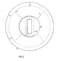
- Figure 2 illustrates the disk of the Figure 1 arrangement in larger scale.
- the disk 3 comprises two laminates, each comprising a plastics film and a non-woven material.
- the plastics films are lain against one another and the laminates are joined along the circular joining line 5 and along radial joining beads 7 extending from the circular line and inwards.
- the laminates are thus totally separated outside the circular line 5 with peripheral portions intended to lie on both sides of the peripheral portion of the hole in the surgical sheet.
- a central recess 8 Arranged in the laminate remote from the patient in the in-use position of the disk is a central recess 8 having a diameter which is greater than the greatest extension of the opening 4.
- the recess 8 provides a worksurface which is free from absorbent material on the underlying laminate. It is, of course, suitable to have around the actual operation wound an area which can be readily swabbed or dried.
- the recess 8 and the joining lines 5,7 give rise to readily accessible pockets 9 between the two laminates. These pockets are suitable accomodations for various auxiliary devices to which rapid access is required during an operation.
- Absorbent material may also be placed in the pockets. This absorbent material can either be incorporated permanently during the manufacture of the sheet, or can be placed in the finished pockets manually.
- the disk 3 is adjusted to the desired position and is then secured in this position with the aid of a pressure-sensitive binder, which is placed in a region 10 around the opening 4.
- the disk 3 need not be permanently fixed in the surgical sheet, but may have the form of a separate unit which is turned to the position desired and fixed in this position, either to the body of the patient or to the sheet.
- the recess 8 may be fully covered with a laminate structure which is formed similarly to the laminate layer in general but is separated therefrom by a perforated line.
Landscapes
- Health & Medical Sciences (AREA)
- Surgery (AREA)
- Life Sciences & Earth Sciences (AREA)
- Engineering & Computer Science (AREA)
- Biomedical Technology (AREA)
- Heart & Thoracic Surgery (AREA)
- Medical Informatics (AREA)
- Molecular Biology (AREA)
- Animal Behavior & Ethology (AREA)
- General Health & Medical Sciences (AREA)
- Public Health (AREA)
- Veterinary Medicine (AREA)
- Materials For Medical Uses (AREA)
- Accommodation For Nursing Or Treatment Tables (AREA)
- Professional, Industrial, Or Sporting Protective Garments (AREA)
- Orthopedics, Nursing, And Contraception (AREA)
- Media Introduction/Drainage Providing Device (AREA)
- Surgical Instruments (AREA)
Abstract
Description
- The present invention relates to an arrangement in surgical sheets which are provided with at least one through-passing relatively large hole which, when using the sheet, is intended to be positioned over the area of a patient at which an operation is to be performed.
- At present there are to be found two separate surgical sterilized sheet-systems with which a patient can be covered in a sterile fashion in conjunction with surgical operations. One such system is a multi-sheet system, in which, for example, four separate sheets are placed in mutually overlapping relationship in a manner to cover the patient while leaving exposed the body area at which the operation is to be performed, Multi-sheet systems also include so-called wear-sheets, which may comprise, for example, a sheet having a U-shaped edge slit therein, this sheet being placed with the slit located in the body region where an incision is to be made, and one or more additional sheets for covering the remainder of the patient. Although with a multi-sheet system it is possible to arrange the various sheets in a manner suitable to perform the majority of operation incisions, the actual task of laying and arranging the sheets is both complicated and time consuming. As will be understood, the fact that the sheets of such a system must be manipulated a large number of time in order to cover the patient satisfactorily, means that the risk of contamination is greater than when the sterilized sheets can be lain with fewer manipulations.
- The other of the abovementioned two systems comprises the use of so-called hole-sheets. One serious disadvantage with this system is that a large number of sheets with mutually different hole configuration must be available, in order to enable different operations to be performed.
- In accordance with the invention there is now provided an arrangement with which the aforementioned disadvantages associated with known sheet-laying or sheet-covering systems are fully eliminated.
- Taking its point of departure from a surgical sheet of the kind described in the introduction, an arrangement according to the invention is mainly characterized by a preferably circular disk which has therein an elongated relatively small opening and which comprises at least two layers, of which one is formed from a liquid-impermeable material, which disk covers the hole in the surgical sheet, can be adjusted to selected positions of rotation with the longitudinal axis of the elongated opening extending along the line of the intended incision, and is provided with fastener means, for example self-adhesive binder, for securing the disk in its adjusted position in relation to the sheet and/or the body of the patient.
- In accordance with a preferred embodiment of this arrangement, the disk comprises two liquid-impermeable layers, which are turned towards each other and are mutually joined along a substantially peripheral line defining the disk-opening and along a plurality of radially extending lines, and that the layer remote from the patient when the disk is in use has a central circular recess whose diameter exceeds the length of the disk-opening, thereby to form firstly a worksurface located around the disk-opening, and secondly a plurality of pockets which are open towards the worksurface and which are defined laterally by adjacently lying radial connecting lines and at the bottom by the peripherally extending connecting line, and which serve to take-up liquid and/or surgical auxiliary devices.
- The disk is preferably permanently fixed in the through-passing hole in the surgical sheet, wherewith peripheral parts of the layers of material in the disk overlap mutually opposite sheet parts located nearest the hole and the material layers are joined at least along a circumferential line radially within the peripheral portions.
- The invention will now be described in more detail with reference to an embodiment thereof illustrated in the accompanying drawings, in which Figure 1 is a perspective view of an arrangement according to the-invention in its in-use position, and Figure 2 is a plan view in larger scale of an embodiment of the disk forming part of the arrangement.
- In the embodiment illustrated in Figure 1, the surgical sheet comprises a first sheet-part 1 which is intended to cover the patient and the operating table, and a second sheet-part 2, which is intended to be placed over an anesthesis arch, to screen the anesthetizing personnel from the operating area. In the first sheet-part 1 there is formed a through-passing hole, which is preferably circular in shape and which when using the sheet is placed over the area of the patient in which the operation is to be performed. Permanently arranged in the hole is a disk 3 with a circular periphery. The disk is rotatable relative to the sheet and is provided with a central opening 4. The disk of the illustrated embodiment comprises a plurality of layers of liquid-impermeable and liquid-permeable absorbent material. The various layers are joined along a circular line 5, the circumference of which is smaller than, or essentially equal to the hole in the sheet. The disk 3 has a peripheral portion 6 located radially outwards of the circular line 5. This peripheral portion overlaps the sheet portions located nearest the hole, wherewith the peripheral portions of one or more disk layers are located on the inside of the sheet and the peripheral portions of the remaining disk layers are located on the outside of the sheet. The surgical sheet itself suitably comprises two layers of non-woven material sandwiching therebetween a plastics film. The disk, which is described more fully hereinafter with reference to Figure 2, is composed of similar material, and suitably comprises two laminates of a plastics film and a non-woven material. The material of which both the disk and the sheet are comprised is suitably chosen or treated so as to obtain but small friction between the mutually overlapping portions of the disk and the sheet.
- When using an arrangement according to the invention, the surgical sheet is placed, while folded, with the disk located over the operation area, in the illustrated embodiment over the abdomen of the patient. The disk is turned so as to position the opening 4 along the intended surgical incision and is secured in its adjusted position to the patient, whereafter the sheet is unfolded. Because the disk can be rotated in accordance with the invention similar surgical sheets can be used for surgical operations on the breasts, abdomen and hip regions of patients. All that is required is for the sheet to be displaced laterally.
- Figure 2 illustrates the disk of the Figure 1 arrangement in larger scale. As beforementioned, the disk 3 comprises two laminates, each comprising a plastics film and a non-woven material. The plastics films are lain against one another and the laminates are joined along the circular joining line 5 and along radial joining
beads 7 extending from the circular line and inwards. The laminates are thus totally separated outside the circular line 5 with peripheral portions intended to lie on both sides of the peripheral portion of the hole in the surgical sheet. - Arranged in the laminate remote from the patient in the in-use position of the disk is a
central recess 8 having a diameter which is greater than the greatest extension of the opening 4. Therecess 8 provides a worksurface which is free from absorbent material on the underlying laminate. It is, of course, suitable to have around the actual operation wound an area which can be readily swabbed or dried. Therecess 8 and thejoining lines 5,7 give rise to readily accessible pockets 9 between the two laminates. These pockets are suitable accomodations for various auxiliary devices to which rapid access is required during an operation. Absorbent material may also be placed in the pockets. This absorbent material can either be incorporated permanently during the manufacture of the sheet, or can be placed in the finished pockets manually. The disk 3 is adjusted to the desired position and is then secured in this position with the aid of a pressure-sensitive binder, which is placed in aregion 10 around the opening 4. - The invention is not limited to the aforedescribed embodiment, and various modifications can be made within the scope of the following Claims.
- For example, the disk 3 need not be permanently fixed in the surgical sheet, but may have the form of a separate unit which is turned to the position desired and fixed in this position, either to the body of the patient or to the sheet.
- It will be understood that the provision of pockets is not a necessity.
- Prior to using the disk, the
recess 8 may be fully covered with a laminate structure which is formed similarly to the laminate layer in general but is separated therefrom by a perforated line.
Claims (8)
Priority Applications (1)
| Application Number | Priority Date | Filing Date | Title |
|---|---|---|---|
| AT84850304T ATE30668T1 (en) | 1983-10-28 | 1984-10-16 | ARRANGEMENT IN SURGICAL DRAPES. |
Applications Claiming Priority (2)
| Application Number | Priority Date | Filing Date | Title |
|---|---|---|---|
| SE8305944 | 1983-10-28 | ||
| SE8305944A SE439728B (en) | 1983-10-28 | 1983-10-28 | DEVICE ON OPERATION SHEET |
Publications (3)
| Publication Number | Publication Date |
|---|---|
| EP0140857A2 true EP0140857A2 (en) | 1985-05-08 |
| EP0140857A3 EP0140857A3 (en) | 1985-12-27 |
| EP0140857B1 EP0140857B1 (en) | 1987-11-11 |
Family
ID=20353103
Family Applications (1)
| Application Number | Title | Priority Date | Filing Date |
|---|---|---|---|
| EP84850304A Expired EP0140857B1 (en) | 1983-10-28 | 1984-10-16 | An arrangement in surgical sheets |
Country Status (6)
| Country | Link |
|---|---|
| US (1) | US4607631A (en) |
| EP (1) | EP0140857B1 (en) |
| AT (1) | ATE30668T1 (en) |
| CA (1) | CA1220996A (en) |
| DE (2) | DE140857T1 (en) |
| SE (1) | SE439728B (en) |
Cited By (2)
| Publication number | Priority date | Publication date | Assignee | Title |
|---|---|---|---|---|
| WO1995010986A1 (en) * | 1993-10-18 | 1995-04-27 | Kimberly-Clark Corporation | Surgical drape and method of assembly |
| WO1996000045A1 (en) * | 1994-06-23 | 1996-01-04 | Bjoerklund Mats | Reusable operation drape |
Families Citing this family (9)
| Publication number | Priority date | Publication date | Assignee | Title |
|---|---|---|---|---|
| SE457690B (en) * | 1987-05-15 | 1989-01-23 | Moelnlycke Ab | OPERATOR SHEET AND PROCEDURES TO MANUFACTURE THIS |
| DE4021353A1 (en) * | 1990-07-05 | 1992-01-09 | Rotecno Ag | MEDICAL OPERATING CLOTH |
| US5082005A (en) * | 1990-12-18 | 1992-01-21 | New England Deaconess Hospital | Surgical access device |
| US5522403A (en) * | 1991-09-16 | 1996-06-04 | Microtek Medical, Inc. | Splash shield |
| US5540979A (en) * | 1994-05-16 | 1996-07-30 | Yahiaoui; Ali | Porous non-woven bovine blood-oxalate absorbent structure |
| US5592952A (en) * | 1995-08-18 | 1997-01-14 | Bohn; William W. | Infection control surgical drape and method of making surgical incision |
| US5586563A (en) * | 1995-10-23 | 1996-12-24 | Minnesota Mining And Manufacturing Company | Method for making a surgical drape |
| GB2438821A (en) * | 2006-06-09 | 2007-12-12 | Christine Freya Pearson | Neonatal swaddler |
| US9737363B2 (en) | 2012-08-10 | 2017-08-22 | Avent, Inc. | Sterile drape for two tiered hospital instrument table |
Citations (2)
| Publication number | Priority date | Publication date | Assignee | Title |
|---|---|---|---|---|
| GB1397342A (en) * | 1972-02-02 | 1975-06-11 | Johnson & Johnson | Reinforced surgical drape |
| US3921627A (en) * | 1974-05-14 | 1975-11-25 | Spartan Mills Inc | Surgical drape with drainage troughs |
Family Cites Families (3)
| Publication number | Priority date | Publication date | Assignee | Title |
|---|---|---|---|---|
| US4024862A (en) * | 1976-05-12 | 1977-05-24 | The Kendall Company | Drape for expanded surgical procedure |
| SE402050B (en) * | 1977-08-26 | 1978-06-19 | Triplus Sjukvardsprod Ab | OPERATING CLOTH INTENDED TO PROTECT THE SARCANTS AROUND AN INCISION |
| US4336797A (en) * | 1980-08-25 | 1982-06-29 | Vincent Latucca | Adjustable surgical drape |
-
1983
- 1983-10-28 SE SE8305944A patent/SE439728B/en not_active IP Right Cessation
-
1984
- 1984-10-16 DE DE198484850304T patent/DE140857T1/en active Pending
- 1984-10-16 CA CA000465495A patent/CA1220996A/en not_active Expired
- 1984-10-16 EP EP84850304A patent/EP0140857B1/en not_active Expired
- 1984-10-16 AT AT84850304T patent/ATE30668T1/en not_active IP Right Cessation
- 1984-10-16 US US06/663,041 patent/US4607631A/en not_active Expired - Lifetime
- 1984-10-16 DE DE8484850304T patent/DE3467293D1/en not_active Expired
Patent Citations (2)
| Publication number | Priority date | Publication date | Assignee | Title |
|---|---|---|---|---|
| GB1397342A (en) * | 1972-02-02 | 1975-06-11 | Johnson & Johnson | Reinforced surgical drape |
| US3921627A (en) * | 1974-05-14 | 1975-11-25 | Spartan Mills Inc | Surgical drape with drainage troughs |
Cited By (2)
| Publication number | Priority date | Publication date | Assignee | Title |
|---|---|---|---|---|
| WO1995010986A1 (en) * | 1993-10-18 | 1995-04-27 | Kimberly-Clark Corporation | Surgical drape and method of assembly |
| WO1996000045A1 (en) * | 1994-06-23 | 1996-01-04 | Bjoerklund Mats | Reusable operation drape |
Also Published As
| Publication number | Publication date |
|---|---|
| CA1220996A (en) | 1987-04-28 |
| EP0140857A3 (en) | 1985-12-27 |
| DE140857T1 (en) | 1985-08-29 |
| US4607631A (en) | 1986-08-26 |
| EP0140857B1 (en) | 1987-11-11 |
| SE439728B (en) | 1985-07-01 |
| SE8305944L (en) | 1985-04-29 |
| SE8305944D0 (en) | 1983-10-28 |
| ATE30668T1 (en) | 1987-11-15 |
| DE3467293D1 (en) | 1987-12-17 |
Similar Documents
| Publication | Publication Date | Title |
|---|---|---|
| EP0140857B1 (en) | An arrangement in surgical sheets | |
| EP0043839B1 (en) | Surgical drape system | |
| US4973314A (en) | Combined dressing and retainer for surgically implanted catheter | |
| US7135606B1 (en) | Wound dressing | |
| US4089331A (en) | Surgical drape with fenestration liner | |
| US4024862A (en) | Drape for expanded surgical procedure | |
| US4627427A (en) | Universal medical cover sheet and process for draping | |
| US5423737A (en) | Transparent hydrogel wound dressing with release tab | |
| US4316455A (en) | Method of draping a surgical patient | |
| US4384573A (en) | Method of using a surgical drape | |
| US4221215A (en) | Anchoring and occluding surgical dressing | |
| US4899762A (en) | Multi-purpose integrated surgical drape, dressing, and closure structure and method | |
| US8079365B2 (en) | Surgical drape with position assisting fenestration | |
| EP0812159B1 (en) | A surgical drape having adhesive margins | |
| US20030036715A1 (en) | Modular bandage | |
| EP0630629A1 (en) | Hydrogel wound dressing product | |
| US3871369A (en) | Self-adhesive surgical apparel and method | |
| RU2002117280A (en) | Dressing to close a wound or incision | |
| US4702237A (en) | Hemorrhoid retainers | |
| US4711236A (en) | Surgical drape | |
| GB2120104A (en) | Bandage construction | |
| US3769971A (en) | Surgical drape | |
| CA2248713A1 (en) | A covering system for operation patients | |
| US20130263867A1 (en) | Surgical drape | |
| US5792088A (en) | Medical dressing system |
Legal Events
| Date | Code | Title | Description |
|---|---|---|---|
| PUAI | Public reference made under article 153(3) epc to a published international application that has entered the european phase |
Free format text: ORIGINAL CODE: 0009012 |
|
| AK | Designated contracting states |
Designated state(s): AT BE CH DE FR GB IT LI LU NL |
|
| ITCL | It: translation for ep claims filed |
Representative=s name: BARZANO' E ZANARDO ROMA S.P.A. |
|
| TCAT | At: translation of patent claims filed | ||
| TCNL | Nl: translation of patent claims filed | ||
| DET | De: translation of patent claims | ||
| PUAL | Search report despatched |
Free format text: ORIGINAL CODE: 0009013 |
|
| AK | Designated contracting states |
Designated state(s): AT BE CH DE FR GB IT LI LU NL |
|
| 17P | Request for examination filed |
Effective date: 19860307 |
|
| 17Q | First examination report despatched |
Effective date: 19870414 |
|
| ITF | It: translation for a ep patent filed |
Owner name: BARZANO' E ZANARDO ROMA S.P.A. |
|
| GRAA | (expected) grant |
Free format text: ORIGINAL CODE: 0009210 |
|
| AK | Designated contracting states |
Kind code of ref document: B1 Designated state(s): AT BE CH DE FR GB IT LI LU NL |
|
| REF | Corresponds to: |
Ref document number: 30668 Country of ref document: AT Date of ref document: 19871115 Kind code of ref document: T |
|
| REF | Corresponds to: |
Ref document number: 3467293 Country of ref document: DE Date of ref document: 19871217 |
|
| ET | Fr: translation filed | ||
| PLBE | No opposition filed within time limit |
Free format text: ORIGINAL CODE: 0009261 |
|
| STAA | Information on the status of an ep patent application or granted ep patent |
Free format text: STATUS: NO OPPOSITION FILED WITHIN TIME LIMIT |
|
| 26N | No opposition filed | ||
| PG25 | Lapsed in a contracting state [announced via postgrant information from national office to epo] |
Ref country code: LU Free format text: LAPSE BECAUSE OF NON-PAYMENT OF DUE FEES Effective date: 19881031 |
|
| PGFP | Annual fee paid to national office [announced via postgrant information from national office to epo] |
Ref country code: LU Payment date: 19891025 Year of fee payment: 6 |
|
| PGFP | Annual fee paid to national office [announced via postgrant information from national office to epo] |
Ref country code: CH Payment date: 19901001 Year of fee payment: 7 |
|
| PGFP | Annual fee paid to national office [announced via postgrant information from national office to epo] |
Ref country code: AT Payment date: 19901010 Year of fee payment: 7 |
|
| PGFP | Annual fee paid to national office [announced via postgrant information from national office to epo] |
Ref country code: NL Payment date: 19901031 Year of fee payment: 7 |
|
| PG25 | Lapsed in a contracting state [announced via postgrant information from national office to epo] |
Ref country code: AT Effective date: 19911016 |
|
| PG25 | Lapsed in a contracting state [announced via postgrant information from national office to epo] |
Ref country code: LI Effective date: 19911031 Ref country code: CH Effective date: 19911031 |
|
| PG25 | Lapsed in a contracting state [announced via postgrant information from national office to epo] |
Ref country code: NL Effective date: 19920501 |
|
| NLV4 | Nl: lapsed or anulled due to non-payment of the annual fee | ||
| REG | Reference to a national code |
Ref country code: CH Ref legal event code: PL |
|
| ITTA | It: last paid annual fee | ||
| PGFP | Annual fee paid to national office [announced via postgrant information from national office to epo] |
Ref country code: FR Payment date: 20010928 Year of fee payment: 18 |
|
| PGFP | Annual fee paid to national office [announced via postgrant information from national office to epo] |
Ref country code: GB Payment date: 20011010 Year of fee payment: 18 |
|
| PGFP | Annual fee paid to national office [announced via postgrant information from national office to epo] |
Ref country code: DE Payment date: 20011019 Year of fee payment: 18 |
|
| PGFP | Annual fee paid to national office [announced via postgrant information from national office to epo] |
Ref country code: BE Payment date: 20011022 Year of fee payment: 18 |
|
| REG | Reference to a national code |
Ref country code: GB Ref legal event code: IF02 |
|
| PG25 | Lapsed in a contracting state [announced via postgrant information from national office to epo] |
Ref country code: GB Free format text: LAPSE BECAUSE OF NON-PAYMENT OF DUE FEES Effective date: 20021016 |
|
| PG25 | Lapsed in a contracting state [announced via postgrant information from national office to epo] |
Ref country code: BE Free format text: LAPSE BECAUSE OF NON-PAYMENT OF DUE FEES Effective date: 20021031 |
|
| BERE | Be: lapsed |
Owner name: *MOLNLYCKE A.B. Effective date: 20021031 |
|
| PG25 | Lapsed in a contracting state [announced via postgrant information from national office to epo] |
Ref country code: DE Free format text: LAPSE BECAUSE OF NON-PAYMENT OF DUE FEES Effective date: 20030501 |
|
| GBPC | Gb: european patent ceased through non-payment of renewal fee |
Effective date: 20021016 |
|
| PG25 | Lapsed in a contracting state [announced via postgrant information from national office to epo] |
Ref country code: FR Free format text: LAPSE BECAUSE OF NON-PAYMENT OF DUE FEES Effective date: 20030630 |
|
| REG | Reference to a national code |
Ref country code: FR Ref legal event code: ST |