EP0140687A2 - Manufacturing mastic asphalt - Google Patents
Manufacturing mastic asphalt Download PDFInfo
- Publication number
- EP0140687A2 EP0140687A2 EP84307396A EP84307396A EP0140687A2 EP 0140687 A2 EP0140687 A2 EP 0140687A2 EP 84307396 A EP84307396 A EP 84307396A EP 84307396 A EP84307396 A EP 84307396A EP 0140687 A2 EP0140687 A2 EP 0140687A2
- Authority
- EP
- European Patent Office
- Prior art keywords
- asphalt
- moulds
- mould
- weight
- cooling
- Prior art date
- Legal status (The legal status is an assumption and is not a legal conclusion. Google has not performed a legal analysis and makes no representation as to the accuracy of the status listed.)
- Withdrawn
Links
Images


Classifications
-
- B—PERFORMING OPERATIONS; TRANSPORTING
- B65—CONVEYING; PACKING; STORING; HANDLING THIN OR FILAMENTARY MATERIAL
- B65B—MACHINES, APPARATUS OR DEVICES FOR, OR METHODS OF, PACKAGING ARTICLES OR MATERIALS; UNPACKING
- B65B63/00—Auxiliary devices, not otherwise provided for, for operating on articles or materials to be packaged
- B65B63/08—Auxiliary devices, not otherwise provided for, for operating on articles or materials to be packaged for heating or cooling articles or materials to facilitate packaging
-
- C—CHEMISTRY; METALLURGY
- C10—PETROLEUM, GAS OR COKE INDUSTRIES; TECHNICAL GASES CONTAINING CARBON MONOXIDE; FUELS; LUBRICANTS; PEAT
- C10C—WORKING-UP PITCH, ASPHALT, BITUMEN, TAR; PYROLIGNEOUS ACID
- C10C3/00—Working-up pitch, asphalt, bitumen
- C10C3/18—Removing in solid form from reaction vessels, containers and the like, e.g. by cutting out, by pressing
Definitions
- the present invention relates to a method and to an installation for producing mastic asphalt and to an improved mastic asphalt block.
- Mastic asphalt has been manufactured previously by methods in which the main constituents of the mastic asphalt, which generally include bitumen, limestone grit and a powdered limestone filler, are mixed and then heated together for further mixing. The resulting molten mixture is then poured into moulds and allowed to cool and solidify into blocks which are convenient for transporting to the sites on which the asphalt is to be used.
- the main constituents of the mastic asphalt which generally include bitumen, limestone grit and a powdered limestone filler
- the apparatus of the invention is characterised in that it comprises means for heating at least some of the constituent materials from which the asphalt is formed prior to mixing, means for mixing the constituent materials, means for cooling the asphalt to a temperature suitable for discharging into a mould and a heat exchanger arrangment . associated with the cooling means for recovering heat from the asphalt and returning it to the heating means for heating the constituent materials for asphalt to be produced subsequently.
- heat should be recovered during the mixing of the constituent materials and used in heating the filler for asphalt mixed subsequently.
- this arrangement has a further advantage.
- mixing of the constituent materials is best carried out at a temperature of around 180°C
- the asphalt is best poured into the moulds at a lower temperature, from around 120 0 C, the optimum temperature being about 150°C.
- the asphalt can be cooled to a temperature ideal for moulding by the time the mixing is complete and the delays which have been necessary in the past while the asphalt is allowed to cool prior to moulding are avoided.
- the entire cooling process may be effected by passing the filled moulds through an array of water spray nozzles in a vertical zig-zag path.
- this arrangement has the advantage that the use of water sprays in removing heat from the moulds is more efficient than immersing the moulds in water because water sprayed onto the surfaces of the moulds in the initial stages of cooling tends to form steam and so large quantities of heat are removed from the moulds as the latent heat needed to turn water into steam is much greater than the heat required to merely heat the water.
- mastic asphalt is usually supplied to the contractors who use it in the form of solid blocks. These blocks generally have a nominal weight of 25kg as this amount can easily be melted in an ordinary bucket. In practice, the blocks vary considerably in weight, size and shape and are, therefore, difficult to stack and store.
- the invention provides a method of discharging mastic asphalt into a plurality of moulds through a discharge outlet which can be selectively opened and closed, characterised in that a method of discharging mastic asphalt into a plurality of moulds through a discharge outlet which can be selectively opened and closed, the method being characterised in that the weight of each mould is measured after filling and the time for which the discharge outlet is opened to discharge asphalt into each mould is varied in response to the measured weight of preceding filled moulds so as to render the weight of asphalt discharged into successive moulds substantially uniform.
- the invention provides a mastic asphalt block characterised in that it has formed in a surface thereof at least one groove for facilitating breaking of the block. When such block is gently tapped it will break, in a controlled manner, along the line of the groove or indentation.
- the method of the invention in its various aspects enables an improved mastic asphalt block to be produced more quickly and cheaply than hitherto.
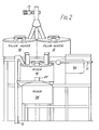
- the manufacturing plant shown in Figs. 1 and 2 enables mastic asphalt to be produced from the raw materials bitumen, limestone grit and powdered limestone filler by an almost completely automatic process.
- Bitumen is delivered hot to the the hopper 10 and is kept warm at a temperature between 170°C and 200°C to render it sufficiently liquid to flow reasonably easily and is then carried directly to the primary mixer 16 through a pipeline 11.
- Grit and filler from the hoppers 12 and 14 respectively are drawn upwards by means of elevators 13 and 15.
- the filler is fed from the hopper 14 into two heaters 18 where it is heated to a temperature of about 200 0 C and then is carried downwards by gravity to the primary mixer 16, either directly, as shown in Fig. 2 or via a weighing hopper 20 as shown in Fig. 1.
- the grit is not heated prior to mixing but is added to the other materials in the primary mixer 16, again, either directly from the hopper 12 or via the weighing hopper 20.
- the mixer 16 may be of the conventional "vertical" mixer type having a mixing vessel of, typically, 6 tonnes capacity with a central vertical rotating shaft carrying one or more sets of angled mixing blades or paddles which effect the mixing of the raw materials to form mastic asphalt.
- the mixer 16 is set to operate on a thirty-minute mixing cycle and once the mixing period is over, a gate is opened at the base of the mixer 16 to allow its contents to be discharged by gravity through a steeply- angled shute 22 into a secondary mixer 24.
- the secondary mixer 24 which is shown in detail in Figs. 3 and 4, serves two purposes. Firstly, it subjects the asphalt to further mixing, so as to ensure that the raw materials are properly blended and the resulting asphalt is as homogeneous as possible, and, secondly, it acts to cool the asphalt, which not only permits heat to be recovered and re-used but also ensures that the asphalt is at the optimum temperature for moulding.
- the mixer 24 is, again of the vertical type consisting of a mixing tank 26 enclosing a central rotary spindle 28 which carries two sets of angled mixing paddles 30.
- Hot asphalt from the primary mixer 16 enters the mixing tank 26 through an opening 32 at the top of the tank 26 and the cooled asphalt is discharged through an outlet valve (treacle valve) or opening at its base which is closed during mixing by a pneumatically-operated gate 34.
- the secondary mixer 24 is also provided with an outer jacket 36 of insulating material which encloses a number of vertical passages 38 for the flow of a heat exchange medium.
- the passages 38 are joined at their upper and lower ends by annular passages 40 and 42 respectively to form a network through which the heat exchange medium, which may, for example, be thermal oil, circulates.
- the heat exchange medium which may, for example, be thermal oil, circulates.
- the cold thermal oil entering the network of passages contacts the hot asphalt through the wall of the mixing tank 26 and heat is transferred from the asphalt to the oil.
- the hot oil then leaves the secondary mixer 24 and passes through a heat exchanger 44 where the heat is removed and returned to the heaters 18 for use in heating filler for the next batch of asphalt.
- the moulds must be cooled so that the asphalt solidifies into fairly rigid blocks.
- Rapid cooling of the filled moulds is achieved by drawing the moulds through an array of water sprays.
- the filled moulds are carried from the filling point at the outlet of the secondary mixer 24 by a suitable form of conveyor into a cooling tower 50, which is shown in Figs. 5 and 6.
- the moulds 52 are coupled to a chain conveyor 54.
- the conveyor 54 runs in a zig-zag path up-and-down along the length of the tower 50 so as to fit as long a path as possible into a relatively small ground area.
- Each vertical span of the chain conveyor may, for example, be about 30 feet (9 metres approximately) in length.
- the chain conveyor 54 is surrounded along its sinuous zig-zag path by an array 56 of nozzles which spray water onto the moulds 52.
- the water which initially contacts the moulds 52 and their contents is turned into steam, thus removing a relatively large quantity of heat from the asphalt in the form of the latent heat needed to turn the water into steam. Thereafter, heat is removed by merely heating the spray water.
- the water temperature rises from about 10 0 C to about 16 0 C .
- the moulds 52 are uncoupled from the conveyor 54 and carried away for the asphalt blocks to be unmoulded and packaged prior to being transported to the sites where the asphalt is to be used.
- the moulds 52 in which the asphalt blocks are formed are conveyed continuously around a closed-loop path which passes through a mould-filling station 53 and an unmoulding station 55.
- the filling of the moulds 52 is regulated by a control system incorporating a micro-processor 60 as shown in Fig. 7.
- Each mould 52 is carried to the mould-filling station 53 which is directly below the discharge gate 34 of the secondary mixer 24.
- the discharge gate 34 is pneumatically-actuated and can be moved to open and close the discharge outlet at the base of the mixer 24.
- asphalt falls vertically under gravity from the outlet into a mould 52 which is positioned directly below it.
- the use of a vertical outlet arrangement avoids the problems due to drag and a build-up of asphalt in the shute which arise when an inclined outlet shute is used.
- the pneumatic actuator 35 of the gate 34 is controlled by the microprocessor 60. As each mould 52 reaches the mould-filling station 53, the microprocessor 60 causes the actuator 35 to open the gate 34. The gate 34 remains open for the period required for a sufficient amount of asphalt to be discharged into the mould 52 to fill it. The gate 34 is then closed.
- the filled mould 52 is then conveyed through a weighing station 64 and a signal representing the weight of the filled mould input into the microprocessor 60.
- the microprocessor 60 compares this signal to a stored value, which can either be a desired nominal weight or an average value or the weight of the next preceding mould.
- the microprocessor 60 then adjusts the time for which the discharge gate 34 is opened to fill subsequent moulds so that the amount of asphalt discharged and, hence the size and weight of the blocks are as consistent as possible.
- each mould may in addition be weighed prior to being filled.
- the signal representing the weight of the empty mould can then be used by the microprocessor to provide a signal representative of the actual weight of asphalt in the mould which is then compared to a desired value.
- the moulds 52 in which the blocks are formed are in the form of a generally rectangular tray consisting of four compartments, each rectangular, having a single integral side wall and a separate spring-biased loose bottom. Each compartment is preferably twice as long as it is wide, for reasons which will be explained in greater detail below, and has a capacity of 20kg of mastic asphalt. Typically, a 20kg block may be 0.5m (20 inches) long and 0.25m (10 inches) wide. To achieve the desired 20kg weight, a mould having these dimensions is filled with mastic asphalt to a depth of 9cm (3b inches).
- the side wall is not quite perpendicular to the bottom but tapers slightly towards it, typically at an angle of about 8° to the perpendicular, so that the asphalt blocks can more easily be removed from the mould.
- the use of a loose bottom in the mould allows the finished block to be simply pushed out of it by suitable unmoulding equipment at the unmoulding station 55.
- each mould Prior to being filled, the inside of each mould is dusted with a little of the powdered limestone filler material to prevent the asphalt sticking to the mould. As a result, the finished blocks tend to have a surface layer of limestone filler which helps to prevent them sticking together.
- the empty moulds 52 are returned by means of a conveyor 57 to the mould-filling station 53 for re-use.
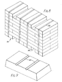
- the blocks produced by the installation of the invention are of a uniform size, they can easily be formed into a self-supporting stack 70, as shown in Fig. 8 of the drawings. For this reason, it is preferred to make the blocks of the rectangular shape described above, as such blocks can be stacked more easily using conventional stacking machinery than blocks of other shapes.
- Each stack 70 is formed by a conventional stacking machine 59 located downstream of the unmoulding station 55 and consists of, in this case, .eight layers of blocks arranged so that the blocks of each layer straddle the gaps between the blocks of the layer below.
- the stack 70 is held together by means of four straps 72 which pass tightly around it to prevent the blocks moving apart.
- spaces are left between adjacent blocks to form channels 74 into which the forks of a fork-lift truck can be inserted to move the stack.
- a stack formed in this way is entirely self-supporting and does not require a pallet or any other form of packing.
- each strap 72 should be left with an end free when initally placed on the stack 70 so that it can be pulled up and retightened immediately before moving the stack 70.
- each compartment of the moulds 52 in which the blocks are formed is formed with two, as shown, or three equally-spaced transverse ribs of triangular cross-section which produce in the finished asphalt block correspondingly spaced, triangular cross-section grooves or indentations 80, as shown in Fig. 9.
- the ribs may either be formed integrally with the bottom plate of the mould or by positioning two pieces of angle iron on the base of the mould.
- the grooved blocks can be broken into even-sized pieces simply by tapping them sharply, thus causing the block to split cleanly in a controlled manner along the line of the grooves 80.
- Grooves 80 of various cross- sectional shapes may be used and provide satisfactory results.
- the groove depth should preferably be between one fifth and one third of the overall height of the block, the best results being obtained when the groove depth is about one quarter of the block height. So for a 0.5 metre long block of the dimensions described above, a groove depth of about 2.25cm (0.9 inch) is preferred.
- the method of the invention enables an improved mastic asphalt block to be manufactured more cheaply by making savings in both the energy consumed and the manufacturing time.
- the plant described above is almost completely automatic and can be operated by as few as two men who may be housed in a small air-conditioned control cabin 90, shown in Fig. 2, thus avoiding the need for personnel to work in the unpleasantly hot areas around the heaters and mixers.
- the plant is very compact and, consequently, occupies relatively little space and it is envisaged that it could be erected on site in instances where large quantities of mastic asphalt will be needed.
Abstract
In an installation for manufacturing mastic asphalt, bitumen from a hopper (10) is kept warm so that it remains sufficiently fluid to enable it to be easily handled and is supplied to a primary mixer (16). Powdered limestone filler from a hopper (14) is heated by means of heaters (18) and is added, together with unheated grit from a hopper (12), to the mixer (16), via a weighing hopper (20). The constituent materials are mixed without further heat input and are then discharged into a secondary mixer (24) where further mixing occurs. The mixer (24) incorporates passages for the circulation of a heat exchange medium which contacts the asphalt to cool it to a temperature suitable for moulding. The heat extracted from the asphalt is returned to the heaters (18) and re-used for heating the filler for asphalt produced subsequently. Asphalt is discharged from the secondary mixer (24) into a plurality of moulds (52) through a pneumatically-actuated gate (34) (see Fig. 3). The gate (34) is operated by a control system incorporating a micro- processor. Each mould (52) is weighed after filling and a signal indicative of the weight of the mould is fed to the micro- processor. The time for which the gate (34) is opened is varied by the microprocessor in response to the measured weight of the mould so as to render the weight of the asphalt blocks produced as consistent as possible. Consequently, the blocks produced are of substantially uniform size and can be formed, after unmoulding, into a self-supporting stack. The filled moulds (52) are conveyed through a cooling tower (50) in which they pass through an array of spray nozzles arranged to spray water onto the moulds (52) so that at least some of the water impinging on the moulds (52) initially forms steam and thereby cools the asphalt. Inside the cooling tower (50) the moulds (52) are conveyed along a vertical zig-zag path so as to fit.
Description
- The present invention relates to a method and to an installation for producing mastic asphalt and to an improved mastic asphalt block.
- Mastic asphalt has been manufactured previously by methods in which the main constituents of the mastic asphalt, which generally include bitumen, limestone grit and a powdered limestone filler, are mixed and then heated together for further mixing. The resulting molten mixture is then poured into moulds and allowed to cool and solidify into blocks which are convenient for transporting to the sites on which the asphalt is to be used.
- A considerable amount of labour is involved in these existing methods and they are wasteful in terms of energy consumption. Consequently the asphalt produced using these methods is relatively expensive.
- Some attempts have already been made to overcome the disadvantages of these existing methods.
- For example, in order to mix bitumen with other materials it is necessary to keep it relatively warm so that it remains in a relatively fluid state otherwise it would simply be too viscous to handle efficiently at all.
- When the warm bitumen is added to the other cold constituent materials, its temperature drops and it must be re-heated before mixing is effected. This cooling and reheating of the bitumen used in manufacturing the asphalt increases the heat energy used in the manufacturing process.
- It has, therefore, been proposed that the energy consumed in the manufacture of mastic asphalt could be reduced by heating the grit before mixing it with the bitumen and grit so that the hot constituent materials can be mixed without supplying further heat to the mixer. This avoids reheating the already hot bitumen and saves considerable energy.
- Even this improved method, however, consumes a great deal of heat energy, and quite a large proportion of this energy is, in practice, simply lost into the atmosphere. The heat loss into the atmosphere is not only wasteful and expensive but also makes the the working area around the mixers very hot which is unpleasant for those persons working there.
- We have appreciated that it would be highly advantageous to recover at least some of the heat which has heretofore been dissipated in the atmosphere and to re-use it for heating the unmixed constituent materials.
- In one aspect, the apparatus of the invention is characterised in that it comprises means for heating at least some of the constituent materials from which the asphalt is formed prior to mixing, means for mixing the constituent materials, means for cooling the asphalt to a temperature suitable for discharging into a mould and a heat exchanger arrangment . associated with the cooling means
for recovering heat from the asphalt and returning it to the heating means for heating the constituent materials for asphalt to be produced subsequently. - In one preferred arrangement it is proposed that heat should be recovered during the mixing of the constituent materials and used in heating the filler for asphalt mixed subsequently.
- In addition to considerably reducing the heat input required, this arrangement has a further advantage. Although mixing of the constituent materials is best carried out at a temperature of around 180°C, the asphalt is best poured into the moulds at a lower temperature, from around 1200C, the optimum temperature being about 150°C. Thus, if the heat exchange takes place in the latter stages of mixing, the asphalt can be cooled to a temperature ideal for moulding by the time the mixing is complete and the delays which have been necessary in the past while the asphalt is allowed to cool prior to moulding are avoided.
- Previously, once the hot asphalt has been poured into the moulds, it has been allowed to cool and solidify naturally. However, the asphalt blocks may take as long as four hours to solidify completely and this not only introduces a great deal of delay into the processing of the asphalt but also necessitates the provision of large areas of space in which the moulds can be stored during cooling.
- We have, therefore, proposed a method of cooling mastic asphalt characterised in that the asphalt is discharged into a plurality of moulds, and the moulds are conveyed through an array of spray nozzles arranged to spray water onto the moulds so that at least some of the water impinging on the moulds forms steam and thereby cools the asphalt; at least a portion of the path along which the moulds are conveyed extending between levels which are spaced from one another in a vertical direction.
- The entire cooling process may be effected by passing the filled moulds through an array of water spray nozzles in a vertical zig-zag path. In addition to enabling the moulds to travel along a relatively long path in quite a small ground area, this arrangement has the advantage that the use of water sprays in removing heat from the moulds is more efficient than immersing the moulds in water because water sprayed onto the surfaces of the moulds in the initial stages of cooling tends to form steam and so large quantities of heat are removed from the moulds as the latent heat needed to turn water into steam is much greater than the heat required to merely heat the water.
- As mentioned above, mastic asphalt is usually supplied to the contractors who use it in the form of solid blocks. These blocks generally have a nominal weight of 25kg as this amount can easily be melted in an ordinary bucket. In practice, the blocks vary considerably in weight, size and shape and are, therefore, difficult to stack and store.
- In a further aspect, the invention provides a method of discharging mastic asphalt into a plurality of moulds through a discharge outlet which can be selectively opened and closed, characterised in that a method of discharging mastic asphalt into a plurality of moulds through a discharge outlet which can be selectively opened and closed, the method being characterised in that the weight of each mould is measured after filling and the time for which the discharge outlet is opened to discharge asphalt into each mould is varied in response to the measured weight of preceding filled moulds so as to render the weight of asphalt discharged into successive moulds substantially uniform.
- The production of asphalt blocks of uniform size has the advantage that the resulting blocks can be formed into a self-supporting stack which is simply strapped for transporting and does not require a pallet or any other form of packing. This is only possible because the blocks are of uniform size.
- On site, it is often desirable to break up the blocks of asphalt to enable them to be melted more easily. Existing blocks are usually broken up by striking them with a hammer and it is quite common for the blocks to break into uneven-sized pieces or into a number of very small fragments which cannot be easily melted. We have appreciated that it would be desirable to split the block evenly into a number of suitabe, evenly sized pieces.
- In a further aspect, the invention provides a mastic asphalt block characterised in that it has formed in a surface thereof at least one groove for facilitating breaking of the block. When such block is gently tapped it will break, in a controlled manner, along the line of the groove or indentation.
- Thus the method of the invention in its various aspects enables an improved mastic asphalt block to be produced more quickly and cheaply than hitherto.
- An embodiment of the invention will now be described in detail with reference to the drawings, in which;
- Fig. 1 is a schematic block diagram showing a mastic asphalt manufacturing plant in accordance with the invention;
- Fig. 2 is a front elevational view of the mixing arrangement of the plant of Fig. 1;
- Fig. 3 is a side elevational view of the secondary mixer of the plant of Fig. 1;
- Fig. 4 is a simplified plan view of the mixer of Fig. 3;
- Fig. 5 is a front elevational view of the cooling tower of the plant of Fig. 1;
- Fig. 6 is a side elevational view of the cooling tower of Fig. 5;
- Fig. 7 is a schematic block diagram of the mould filling station of the plant of Fig. I;
- Fig. 8 is a perspective view of a self-supporting stack of asphalt blocks; and
- Fig. 9 is a perspective view of a single asphalt block.
- The manufacturing plant shown in Figs. 1 and 2 enables mastic asphalt to be produced from the raw materials bitumen, limestone grit and powdered limestone filler by an almost completely automatic process.
- Bulk supplies of bitumen, grit and filler are held in
separate hoppers primary mixer 16 in the proportions necessary to produce the grade of asphalt required. Bitumen is delivered hot to the thehopper 10 and is kept warm at a temperature between 170°C and 200°C to render it sufficiently liquid to flow reasonably easily and is then carried directly to theprimary mixer 16 through apipeline 11. - Grit and filler from the
hoppers elevators - The filler is fed from the
hopper 14 into twoheaters 18 where it is heated to a temperature of about 2000 C and then is carried downwards by gravity to theprimary mixer 16, either directly, as shown in Fig. 2 or via a weighinghopper 20 as shown in Fig. 1. The grit is not heated prior to mixing but is added to the other materials in theprimary mixer 16, again, either directly from thehopper 12 or via the weighinghopper 20. - The heat retained in the bitumen and the filler is sufficient to permit the asphalt to be mixed without further heat input into the
mixer 16. Themixer 16 may be of the conventional "vertical" mixer type having a mixing vessel of, typically, 6 tonnes capacity with a central vertical rotating shaft carrying one or more sets of angled mixing blades or paddles which effect the mixing of the raw materials to form mastic asphalt. Themixer 16 is set to operate on a thirty-minute mixing cycle and once the mixing period is over, a gate is opened at the base of themixer 16 to allow its contents to be discharged by gravity through a steeply-angled shute 22 into asecondary mixer 24. - The
secondary mixer 24, which is shown in detail in Figs. 3 and 4, serves two purposes. Firstly, it subjects the asphalt to further mixing, so as to ensure that the raw materials are properly blended and the resulting asphalt is as homogeneous as possible, and, secondly, it acts to cool the asphalt, which not only permits heat to be recovered and re-used but also ensures that the asphalt is at the optimum temperature for moulding. - The
mixer 24 is, again of the vertical type consisting of amixing tank 26 enclosing a centralrotary spindle 28 which carries two sets ofangled mixing paddles 30. Hot asphalt from theprimary mixer 16 enters themixing tank 26 through anopening 32 at the top of thetank 26 and the cooled asphalt is discharged through an outlet valve (treacle valve) or opening at its base which is closed during mixing by a pneumatically-operatedgate 34. - The
secondary mixer 24 is also provided with anouter jacket 36 of insulating material which encloses a number ofvertical passages 38 for the flow of a heat exchange medium. Thepassages 38 are joined at their upper and lower ends byannular passages mixing tank 26 and heat is transferred from the asphalt to the oil. The hot oil then leaves thesecondary mixer 24 and passes through aheat exchanger 44 where the heat is removed and returned to theheaters 18 for use in heating filler for the next batch of asphalt. - Combining the
secondary mixer 24 with a heat exchange arrangement in this way enables considerable savings in terms of heat energy to be made and, as mentioned above, has the advantage that once the secondary mixing cycle is complete, the asphalt has been cooled to a temperature of around 150oC, which is ideal for moulding. Furthermore, if thesecondary mixer 24 is made sufficiently large for example, of 13 tonnes capacity, the filling of the moulds can be entirely separated from the mixing process with thesecondary mixer 24 acting as a buffer between theprimary mixer 16 and the mould-filling equipment. It is also possible, if desired, to provide further primary mixers which discharge into the same secondary mixer. - Once the asphalt has been poured into the moulds, which is preferably carried out as described in detail below, the moulds must be cooled so that the asphalt solidifies into fairly rigid blocks.
- Rapid cooling of the filled moulds is achieved by drawing the moulds through an array of water sprays. The filled moulds are carried from the filling point at the outlet of the
secondary mixer 24 by a suitable form of conveyor into acooling tower 50, which is shown in Figs. 5 and 6. - Inside the
cooling tower 50 themoulds 52 are coupled to achain conveyor 54. Theconveyor 54 runs in a zig-zag path up-and-down along the length of thetower 50 so as to fit as long a path as possible into a relatively small ground area. Each vertical span of the chain conveyor, may, for example, be about 30 feet (9 metres approximately) in length. - The
chain conveyor 54 is surrounded along its sinuous zig-zag path by anarray 56 of nozzles which spray water onto themoulds 52. The water which initially contacts themoulds 52 and their contents is turned into steam, thus removing a relatively large quantity of heat from the asphalt in the form of the latent heat needed to turn the water into steam. Thereafter, heat is removed by merely heating the spray water. Typically, the water temperature rises from about 100C to about 160 C. - Consequently, the
moulds 52 and their contents are cooled rapidly in a relatively small space. - At the end of the
chain conveyor 54 remote from the mixers, themoulds 52 are uncoupled from theconveyor 54 and carried away for the asphalt blocks to be unmoulded and packaged prior to being transported to the sites where the asphalt is to be used. - As mentioned above, mastic asphalt blocks produced in existing processes tend to vary a great deal in size and shape and are, therefore, difficult to package, because they cannot be stacked, and to transport. Frequently they are also difficult to break up into even-sized pieces. These disadvantages may be overcome in the following manner.
- In the installation of the invention, the
moulds 52 in which the asphalt blocks are formed, are conveyed continuously around a closed-loop path which passes through a mould-fillingstation 53 and anunmoulding station 55. - The filling of the
moulds 52 is regulated by a control system incorporating a micro-processor 60 as shown in Fig. 7. - Each
mould 52 is carried to the mould-fillingstation 53 which is directly below thedischarge gate 34 of thesecondary mixer 24. As mentioned above, thedischarge gate 34 is pneumatically-actuated and can be moved to open and close the discharge outlet at the base of themixer 24. When thegate 34 is open, asphalt falls vertically under gravity from the outlet into amould 52 which is positioned directly below it. The use of a vertical outlet arrangement avoids the problems due to drag and a build-up of asphalt in the shute which arise when an inclined outlet shute is used. - The
pneumatic actuator 35 of thegate 34 is controlled by themicroprocessor 60. As eachmould 52 reaches the mould-fillingstation 53, themicroprocessor 60 causes theactuator 35 to open thegate 34. Thegate 34 remains open for the period required for a sufficient amount of asphalt to be discharged into themould 52 to fill it. Thegate 34 is then closed. - The filled
mould 52 is then conveyed through a weighingstation 64 and a signal representing the weight of the filled mould input into themicroprocessor 60. Themicroprocessor 60 then compares this signal to a stored value, which can either be a desired nominal weight or an average value or the weight of the next preceding mould. Themicroprocessor 60 then adjusts the time for which thedischarge gate 34 is opened to fill subsequent moulds so that the amount of asphalt discharged and, hence the size and weight of the blocks are as consistent as possible. - Alternatively, where single moulds are used, each mould may in addition be weighed prior to being filled. The signal representing the weight of the empty mould can then be used by the microprocessor to provide a signal representative of the actual weight of asphalt in the mould which is then compared to a desired value.
- The
moulds 52 in which the blocks are formed are in the form of a generally rectangular tray consisting of four compartments, each rectangular, having a single integral side wall and a separate spring-biased loose bottom. Each compartment is preferably twice as long as it is wide, for reasons which will be explained in greater detail below, and has a capacity of 20kg of mastic asphalt. Typically, a 20kg block may be 0.5m (20 inches) long and 0.25m (10 inches) wide. To achieve the desired 20kg weight, a mould having these dimensions is filled with mastic asphalt to a depth of 9cm (3b inches). The side wall is not quite perpendicular to the bottom but tapers slightly towards it, typically at an angle of about 8° to the perpendicular, so that the asphalt blocks can more easily be removed from the mould. The use of a loose bottom in the mould allows the finished block to be simply pushed out of it by suitable unmoulding equipment at theunmoulding station 55. - Prior to being filled, the inside of each mould is dusted with a little of the powdered limestone filler material to prevent the asphalt sticking to the mould. As a result, the finished blocks tend to have a surface layer of limestone filler which helps to prevent them sticking together. The empty moulds 52 are returned by means of a
conveyor 57 to the mould-fillingstation 53 for re-use. - Because the blocks produced by the installation of the invention are of a uniform size, they can easily be formed into a self-supporting
stack 70, as shown in Fig. 8 of the drawings. For this reason, it is preferred to make the blocks of the rectangular shape described above, as such blocks can be stacked more easily using conventional stacking machinery than blocks of other shapes. - Each
stack 70 is formed by a conventional stackingmachine 59 located downstream of theunmoulding station 55 and consists of, in this case, .eight layers of blocks arranged so that the blocks of each layer straddle the gaps between the blocks of the layer below. Thestack 70 is held together by means of four straps 72 which pass tightly around it to prevent the blocks moving apart. At the top and bottom of thestack 70, spaces are left between adjacent blocks to formchannels 74 into which the forks of a fork-lift truck can be inserted to move the stack. A stack formed in this way is entirely self-supporting and does not require a pallet or any other form of packing. - Where such stacks are stored for some time before being transported, changes in ambient temperature may cause the blocks to contract and the straps 72 to loosen. It is therefore, preferred that each strap 72 should be left with an end free when initally placed on the
stack 70 so that it can be pulled up and retightened immediately before moving thestack 70. - The loose bottom plate of each compartment of the
moulds 52 in which the blocks are formed is formed with two, as shown, or three equally-spaced transverse ribs of triangular cross-section which produce in the finished asphalt block correspondingly spaced, triangular cross-section grooves or indentations 80, as shown in Fig. 9. The ribs may either be formed integrally with the bottom plate of the mould or by positioning two pieces of angle iron on the base of the mould. - The grooved blocks can be broken into even-sized pieces simply by tapping them sharply, thus causing the block to split cleanly in a controlled manner along the line of the grooves 80. Grooves 80 of various cross- sectional shapes may be used and provide satisfactory results. However, we have found that to enable the block to be broken cleanly, the groove depth should preferably be between one fifth and one third of the overall height of the block, the best results being obtained when the groove depth is about one quarter of the block height. So for a 0.5 metre long block of the dimensions described above, a groove depth of about 2.25cm (0.9 inch) is preferred.
- We have found that, for a 20kg block, the best results are obtained with grooves whose cross-section takes the form of a right-angled isosceles triangle, the sides of which are at least 1 to 16 inches (approximately 2.5-3.5cm) in length. Such grooves can easily be formed using suitably dimensional lengths of angle iron. Although it is possible to use, for example, a similarly-sized groove of equilateral triangle cross-section, blocks having such grooves are more difficult to release from their moulds than those having grooves of right-angled triangle cross-section.
- As will be seen from the above description, the method of the invention enables an improved mastic asphalt block to be manufactured more cheaply by making savings in both the energy consumed and the manufacturing time. Furthermore, the plant described above is almost completely automatic and can be operated by as few as two men who may be housed in a small air-conditioned
control cabin 90, shown in Fig. 2, thus avoiding the need for personnel to work in the unpleasantly hot areas around the heaters and mixers. In addition, the plant is very compact and, consequently, occupies relatively little space and it is envisaged that it could be erected on site in instances where large quantities of mastic asphalt will be needed.
Claims (36)
1. A method of cooling mastic asphalt characterised in that the asphalt is discharged into a plurality of moulds, and the moulds are conveyed through an array of spray nozzles arranged to spray water onto the moulds so that at least some of the water impinging on the moulds forms steam and thereby cools the asphalt; at least a portion of the path along which the moulds are conveyed extending between levels which are spaced from one another in a vertical direction.
2. A method according to claim 1 in which each mould is conveyed along a sinuous or zig-zag path through the array of spray nozzles.
3. A method according to claim 2 in which the sinuous or zig-zag path lies in a substantially vertical plane.
4. A method according to claim 2 or 3 in which the moulds are conveyed by means of a continuous conveyor.
5. A method of manufacturing mastic asphalt, characterised in that it comprises the steps of
at least some of the heat removed from the asphalt during cooling being recovered and re-used in heating the constituent materials of asphalt manufactured subsequently.
(a) heating at least some of the constituent materials which are to be combined to form the asphalt;
(b) mixing the constituent materials; and
(c) cooling the asphalt to a temperature suitable for discharging into a mould;
at least some of the heat removed from the asphalt during cooling being recovered and re-used in heating the constituent materials of asphalt manufactured subsequently.
6. A method according to claim 5 in which mixing is effected without further heating of the constituent materials.
7. A method according to claim 5 or 6 in which the cooling is effected during the latter stages of mixing.
8. A method according to any of claims 5 to 7 in which cooling is effected by bringing the asphalt into thermal contact with a heat exchange medium.
9. A method according to claim 8 in which the heat exchange medium is brought into thermal contact with the asphalt during mixing of the constituent materials.
10. A method according to any preceding claim in which the cooled asphalt is discharged into a plurality of moulds through a discharge outlet which can be selectively opened and closed, the weight of each successive mould being measured after filling and the length of time for which the discharge outlet is opened to discharge asphalt into each mould being varied in response to the measured weight of preceding filled moulds so as to render the weight of asphalt discharged into successive moulds substantially uniform.
11. A method of discharging mastic asphalt into a plurality of moulds through a discharge outlet which can be selectively opened and closed, the method being characterised in that the weight of each mould is measured after filling and the time for which the discharge outlet is opened to discharge asphalt into each mould is varied in response to the measured weight of preceding filled moulds so as to render the weight of asphalt discharged into successive moulds substantially uniform.
12. A method according to claim 10 or 11 in which the said measured weight is compared to a stored value, the time for which the discharge outlet is opened being varied in dependence on the difference between the said measured weight and the stored value.
13. A method according to claim 12 in which the stored value is the measured weight of a preceding mould.
14. A method according to any of claims 5 to 13 in which the asphalt is cooled subsequently to being discharged into a plurality of moulds; cooling of the asphalt being effected by spraying water onto the moulds so that at least some of the water impinging on the mould forms steam and thereby cools the asphalt.
15. Apparatus for the manufacture of mastic asphalt characterised in that it comprises means (15) for heating at least some of the constituent materials from which the asphalt is formed prior to mixing, means for mixing the constituent materials, means (24) for cooling the asphalt to a temperature suitable for discharging into a mould (52) and a heat exchanger arrangment (36,38) associated with the cooling means (24) for recovering heat from the asphalt and returning it to the heating means (18) for heating the constituent materials for asphalt to be produced subsequently.
16. Apparatus according to claim 15 in which the means for mixing includes a primary mixer (16) arranged to discharge its contents into a secondary mixer (24) which forms the cooling means.
17. Apparatus according to claim 16 in which two or more primary mixers (16) are arranged to discharge their contents into a single secondary mixer (24).
18. Apparatus according to claim 16 or 17 in which the walls of the secondary mixer (24) are formed with at least one passage (38) for the circulation of a heat exchange medium.
19. Apparatus according to claim 18 in which the heat exchange medium is oil.
20. Apparatus according to any of claims 15 to 19 including means (53) for discharging asphalt into a plurality of moulds (52) through a discharge outlet (34) provided in the cooling means (24), the discharging means (53) including means (64) for weighing each mould (52) after filling and for providing a signal indicative of the weight of each mould and control apparatus (60) coupled to receive the said signal and to vary the time for which the discharge outlet (34) is opened to discharge asphalt into each mould (52) in dependence on the said signal so as to render the weight of asphalt discharged into successive moulds substantially uniform.
21. Apparatus for use in the method of claim 11 comprising means (64) for weighing each mould (52) after filling and for producing a signal indicative of the weight of each mould and control apparatus (60) coupled to receive the said signal and to vary the time for which the discharge outlet (34) is opened to discharge material into each mould (52) in dependence on the said signal so as to render the weight of material discharged into successive moulds substantially uniform.
22. Appparatus according to claim 20 or 21 in which the control apparatus (60) includes a microprocessor.
23. Apparatus according to any of claims 20 to 22 in which the discharge outlet (34) can be selectively opened and closed by means of a pneumatically-activated movable closure.
24. Apparatus according to any of claims 15 to 23 including means for cooling the asphalt subsequently to its having been discharged into a plurality of moulds, the means for cooling comprising an array of spray nozzles (56) and a conveyor (54) for conveying the moulds (52) through the said array; the spray nozzles (56) being arranged to spray water onto the moulds (52) carried by the conveyor (54) so that at least some of the water impinging on the moulds (52) forms steam and thereby cools the asphalt and the conveyor (54) being such that at least a portion of the path along which the moulds (52) are conveyed extends between levels which are spaced from one another in a vertical direction.
25. Apparatus for use in the method of claim 1 comprising means (53) for discharging the asphalt into a plurality of moulds, an array of spray nozzles (56) and a conveyor (54) for conveying the moulds (52) through the said array; the spray nozzles (56) being arranged to spray water onto moulds (52) carried by the conveyor (54) so that at least some of the water impinging on the moulds forms steam and thereby cools the material and the conveyor (54) being such that at lest a portion of the path along which the moulds are conveyed extends between levels which are spaced from one another in a vertical direction.
26. Apparatus according to claim 24 or 25 in which the conveyor (54) is arranged to convey the moulds (52) along a sinuous or zig-zag path through the array of spray nozzles.
27. Apparatus according to claim 26 in which the sinuous or zig-zag path lies in a substantially vertical plane.
28. Apparatus according to any of claims 24 to 27 including means (55) for removing the asphalt from the moulds (52) subsequently to being conveyed through the array of spray nozzles (56).
29. A mastic asphalt block characterised in that it has formed in a surface thereof at least one groove (80) for facilitating breaking of the block.
30. A block according to claim 29 in which the groove (80) extends from one surface of the block to a surface opposite the said one surface.
31. A block according to claim 29 or 30 in which the groove (80) is of triangular cross-section.
32. A block according to claim 31 in which the groove (80) is of right-angled isosceles triangle cross-section.
33. A block according to any of claims 29 to 32 in which the depth of each groove (80) is in the range one fifth to one third of the thickness of the block in a direction substantially perpendicular to the surface in which the groove is formed.
34. A block according to claim 33 in whcih the depth of each groove (80) is one quarter of the said thickness.
35. A block according to any of claims 29 to 34 in which the width of the block is one half of its length.
36. A block according to any of claims 29 to 35 which tapers towards the surface in which the groove is formed.
Applications Claiming Priority (2)
| Application Number | Priority Date | Filing Date | Title |
|---|---|---|---|
| GB08328877A GB2148778B (en) | 1983-10-28 | 1983-10-28 | Manufacturing mastic asphalt blocks |
| GB8328877 | 1983-10-28 |
Publications (2)
| Publication Number | Publication Date |
|---|---|
| EP0140687A2 true EP0140687A2 (en) | 1985-05-08 |
| EP0140687A3 EP0140687A3 (en) | 1987-04-22 |
Family
ID=10550894
Family Applications (1)
| Application Number | Title | Priority Date | Filing Date |
|---|---|---|---|
| EP84307396A Withdrawn EP0140687A3 (en) | 1983-10-28 | 1984-10-26 | Manufacturing mastic asphalt |
Country Status (2)
| Country | Link |
|---|---|
| EP (1) | EP0140687A3 (en) |
| GB (2) | GB2148778B (en) |
Cited By (2)
| Publication number | Priority date | Publication date | Assignee | Title |
|---|---|---|---|---|
| WO1998042792A2 (en) * | 1997-03-26 | 1998-10-01 | Reichhold Chemicals, Inc. | Methods and apparatus for preparing or packaging a hot melt adhesive |
| EP1053181A1 (en) * | 1997-12-12 | 2000-11-22 | Owens Corning | Asphalt packages with consumable containers |
Families Citing this family (1)
| Publication number | Priority date | Publication date | Assignee | Title |
|---|---|---|---|---|
| GB9025910D0 (en) * | 1990-11-28 | 1991-01-09 | Dickinson John E | Bicycle carrier for a caravan |
Citations (3)
| Publication number | Priority date | Publication date | Assignee | Title |
|---|---|---|---|---|
| DE516355C (en) * | 1928-11-21 | 1931-01-22 | Oppermann & Deichmann | Device for making mastic breads |
| DE2359760B2 (en) * | 1972-12-01 | 1978-03-23 | Giorgio Mailand Levy (Italien) | Method and device for the production of stackable bitumen blocks |
| EP0088258A1 (en) * | 1982-02-26 | 1983-09-14 | Cesare Sangiorgi | Production line for bitumen cakes |
Family Cites Families (6)
| Publication number | Priority date | Publication date | Assignee | Title |
|---|---|---|---|---|
| GB169322A (en) * | 1920-07-12 | 1921-09-29 | Armstrong John | Improvements in and relating to the manufacture of briquettes |
| GB461815A (en) * | 1935-08-24 | 1937-02-24 | Karl Bray Kilborn | Improvements in or relating to the manufacture of hollow rubber articles and articles made of sponge rubber |
| GB531386A (en) * | 1939-11-14 | 1941-01-02 | Kathleen Annie Throssell | Improvements in and relating to slabs or blocks of material, for example chocolate, intended to be broken along weakening lines |
| GB697071A (en) * | 1952-01-08 | 1953-09-16 | Robert Sollich | Improvements in flexible moulds for casting settable or hardenable plastic substances for example jellies, sugar masses or fondant centres |
| GB944066A (en) * | 1961-02-20 | 1963-12-11 | Glynercast Ltd | Improvements relating to building blocks |
| DE2614804A1 (en) * | 1976-04-06 | 1977-10-27 | Resicoat Gmbh | COOLING DEVICE FOR COOLING CONTINUOUS PRODUCT VOLUME |
-
1983
- 1983-10-28 GB GB08328877A patent/GB2148778B/en not_active Expired
-
1984
- 1984-10-26 GB GB08427197A patent/GB2152425A/en not_active Withdrawn
- 1984-10-26 EP EP84307396A patent/EP0140687A3/en not_active Withdrawn
Patent Citations (3)
| Publication number | Priority date | Publication date | Assignee | Title |
|---|---|---|---|---|
| DE516355C (en) * | 1928-11-21 | 1931-01-22 | Oppermann & Deichmann | Device for making mastic breads |
| DE2359760B2 (en) * | 1972-12-01 | 1978-03-23 | Giorgio Mailand Levy (Italien) | Method and device for the production of stackable bitumen blocks |
| EP0088258A1 (en) * | 1982-02-26 | 1983-09-14 | Cesare Sangiorgi | Production line for bitumen cakes |
Cited By (5)
| Publication number | Priority date | Publication date | Assignee | Title |
|---|---|---|---|---|
| WO1998042792A2 (en) * | 1997-03-26 | 1998-10-01 | Reichhold Chemicals, Inc. | Methods and apparatus for preparing or packaging a hot melt adhesive |
| WO1998042792A3 (en) * | 1997-03-26 | 1998-12-03 | Reichhold Chemicals Inc | Methods and apparatus for preparing or packaging a hot melt adhesive |
| US6006497A (en) * | 1997-03-26 | 1999-12-28 | Reichhold Chemicals, Inc. | Methods and apparatus for preparing a hot melt adhesive |
| EP1053181A1 (en) * | 1997-12-12 | 2000-11-22 | Owens Corning | Asphalt packages with consumable containers |
| EP1053181A4 (en) * | 1997-12-12 | 2002-05-22 | Owens Corning Fiberglass Corp | Asphalt packages with consumable containers |
Also Published As
| Publication number | Publication date |
|---|---|
| GB8427197D0 (en) | 1984-12-05 |
| GB2148778A (en) | 1985-06-05 |
| GB2152425A (en) | 1985-08-07 |
| EP0140687A3 (en) | 1987-04-22 |
| GB2148778B (en) | 1987-06-24 |
| GB8328877D0 (en) | 1983-11-30 |
Similar Documents
| Publication | Publication Date | Title |
|---|---|---|
| US7942658B1 (en) | Systems for forming lightweight concrete block | |
| EP1257407B1 (en) | Building products | |
| EP3592523B1 (en) | Aggregate cooling system and method | |
| US2993235A (en) | Method for making reinforced resin products | |
| KR101563363B1 (en) | Ferro silicon molding method | |
| EP0140687A2 (en) | Manufacturing mastic asphalt | |
| CN107775000A (en) | A kind of high specific gravity is to pouring weight hot press forming technology | |
| US4159911A (en) | Method of mixing steel fiber reinforced concrete | |
| US3305138A (en) | Apparatus for storing and distributing heated asphalt mix | |
| CN105358716A (en) | Casting apparatus and method of controlling said apparatus | |
| US5682758A (en) | Method and apparatus for cooling asphalt | |
| US20040177596A1 (en) | Methods of manufacturing roofing products | |
| EP0059411B1 (en) | Apparatus for spreading covering material | |
| CN209508764U (en) | A kind of cold mixing cold laid asphaltic mixture piecemeal forming device | |
| DE1508039C3 (en) | ||
| US4098563A (en) | Concrete product manufacturing system | |
| US4004619A (en) | Method and apparatus for preparing and packaging mastic coating material | |
| SE458599B (en) | PROCEDURES AND EQUIPMENT FOR PACKAGING THE REFUELY MOLDED BITUMM IN POLYMER FILM | |
| US805702A (en) | Apparatus for producing vitrified bricks, tiles, and other articles. | |
| DE3625385A1 (en) | Process for packaging viscous bitumen in polyethylene film containers | |
| EP0561414B1 (en) | Casting method for forming a resin molding | |
| EP0136405B1 (en) | Casting and cooling line for liquid material, particularly for calciumcarbide | |
| WO2001020093A1 (en) | Lightweight concrete block | |
| CN217169124U (en) | Heat preservation proportioning machine | |
| CN109176859B (en) | Full-automatic extrusion forming light wallboard production line |
Legal Events
| Date | Code | Title | Description |
|---|---|---|---|
| PUAI | Public reference made under article 153(3) epc to a published international application that has entered the european phase |
Free format text: ORIGINAL CODE: 0009012 |
|
| AK | Designated contracting states |
Designated state(s): AT BE CH DE FR IT LI LU NL SE |
|
| PUAL | Search report despatched |
Free format text: ORIGINAL CODE: 0009013 |
|
| AK | Designated contracting states |
Kind code of ref document: A3 Designated state(s): AT BE CH DE FR IT LI LU NL SE |
|
| STAA | Information on the status of an ep patent application or granted ep patent |
Free format text: STATUS: THE APPLICATION IS DEEMED TO BE WITHDRAWN |
|
| 18D | Application deemed to be withdrawn |
Effective date: 19871023 |
|
| RIN1 | Information on inventor provided before grant (corrected) |
Inventor name: POPE, BRYAN |